WO2023181861A1 - アーティキュレート式車両 - Google Patents
アーティキュレート式車両 Download PDFInfo
- Publication number
- WO2023181861A1 WO2023181861A1 PCT/JP2023/008140 JP2023008140W WO2023181861A1 WO 2023181861 A1 WO2023181861 A1 WO 2023181861A1 JP 2023008140 W JP2023008140 W JP 2023008140W WO 2023181861 A1 WO2023181861 A1 WO 2023181861A1
- Authority
- WO
- WIPO (PCT)
- Prior art keywords
- reference point
- articulated vehicle
- control device
- traveling direction
- work site
- Prior art date
Links
Images


Classifications
-
- B—PERFORMING OPERATIONS; TRANSPORTING
- B62—LAND VEHICLES FOR TRAVELLING OTHERWISE THAN ON RAILS
- B62D—MOTOR VEHICLES; TRAILERS
- B62D12/00—Steering specially adapted for vehicles operating in tandem or having pivotally connected frames
-
- E—FIXED CONSTRUCTIONS
- E02—HYDRAULIC ENGINEERING; FOUNDATIONS; SOIL SHIFTING
- E02F—DREDGING; SOIL-SHIFTING
- E02F9/00—Component parts of dredgers or soil-shifting machines, not restricted to one of the kinds covered by groups E02F3/00 - E02F7/00
- E02F9/20—Drives; Control devices
- E02F9/2058—Electric or electro-mechanical or mechanical control devices of vehicle sub-units
- E02F9/2087—Control of vehicle steering
-
- B—PERFORMING OPERATIONS; TRANSPORTING
- B62—LAND VEHICLES FOR TRAVELLING OTHERWISE THAN ON RAILS
- B62D—MOTOR VEHICLES; TRAILERS
- B62D11/00—Steering non-deflectable wheels; Steering endless tracks or the like
- B62D11/001—Steering non-deflectable wheels; Steering endless tracks or the like control systems
- B62D11/003—Electric or electronic control systems
-
- B—PERFORMING OPERATIONS; TRANSPORTING
- B62—LAND VEHICLES FOR TRAVELLING OTHERWISE THAN ON RAILS
- B62D—MOTOR VEHICLES; TRAILERS
- B62D15/00—Steering not otherwise provided for
- B62D15/02—Steering position indicators ; Steering position determination; Steering aids
- B62D15/025—Active steering aids, e.g. helping the driver by actively influencing the steering system after environment evaluation
-
- E—FIXED CONSTRUCTIONS
- E02—HYDRAULIC ENGINEERING; FOUNDATIONS; SOIL SHIFTING
- E02F—DREDGING; SOIL-SHIFTING
- E02F9/00—Component parts of dredgers or soil-shifting machines, not restricted to one of the kinds covered by groups E02F3/00 - E02F7/00
- E02F9/20—Drives; Control devices
-
- E—FIXED CONSTRUCTIONS
- E02—HYDRAULIC ENGINEERING; FOUNDATIONS; SOIL SHIFTING
- E02F—DREDGING; SOIL-SHIFTING
- E02F9/00—Component parts of dredgers or soil-shifting machines, not restricted to one of the kinds covered by groups E02F3/00 - E02F7/00
- E02F9/26—Indicating devices
- E02F9/264—Sensors and their calibration for indicating the position of the work tool
- E02F9/265—Sensors and their calibration for indicating the position of the work tool with follow-up actions (e.g. control signals sent to actuate the work tool)
-
- G—PHYSICS
- G05—CONTROLLING; REGULATING
- G05D—SYSTEMS FOR CONTROLLING OR REGULATING NON-ELECTRIC VARIABLES
- G05D1/00—Control of position, course, altitude or attitude of land, water, air or space vehicles, e.g. using automatic pilots
- G05D1/40—Control within particular dimensions
- G05D1/43—Control of position or course in two dimensions
-
- G—PHYSICS
- G05—CONTROLLING; REGULATING
- G05D—SYSTEMS FOR CONTROLLING OR REGULATING NON-ELECTRIC VARIABLES
- G05D1/00—Control of position, course, altitude or attitude of land, water, air or space vehicles, e.g. using automatic pilots
- G05D1/60—Intended control result
- G05D1/646—Following a predefined trajectory, e.g. a line marked on the floor or a flight path
-
- G—PHYSICS
- G01—MEASURING; TESTING
- G01C—MEASURING DISTANCES, LEVELS OR BEARINGS; SURVEYING; NAVIGATION; GYROSCOPIC INSTRUMENTS; PHOTOGRAMMETRY OR VIDEOGRAMMETRY
- G01C21/00—Navigation; Navigational instruments not provided for in groups G01C1/00 - G01C19/00
- G01C21/20—Instruments for performing navigational calculations
-
- G—PHYSICS
- G05—CONTROLLING; REGULATING
- G05D—SYSTEMS FOR CONTROLLING OR REGULATING NON-ELECTRIC VARIABLES
- G05D2105/00—Specific applications of the controlled vehicles
- G05D2105/05—Specific applications of the controlled vehicles for soil shifting, building, civil engineering or mining, e.g. excavators
-
- G—PHYSICS
- G05—CONTROLLING; REGULATING
- G05D—SYSTEMS FOR CONTROLLING OR REGULATING NON-ELECTRIC VARIABLES
- G05D2107/00—Specific environments of the controlled vehicles
- G05D2107/90—Building sites; Civil engineering
-
- G—PHYSICS
- G05—CONTROLLING; REGULATING
- G05D—SYSTEMS FOR CONTROLLING OR REGULATING NON-ELECTRIC VARIABLES
- G05D2109/00—Types of controlled vehicles
- G05D2109/10—Land vehicles
- G05D2109/16—Articulated vehicles, e.g. snake-like robots
Definitions
- the present invention relates to an articulated vehicle.
- articulated vehicles have been used at construction sites, etc., but the demand for automatic driving of articulated vehicles is increasing due to reasons such as a shortage of operators.
- the widespread use of autonomous driving in articulated vehicles requires route-following performance that does not meander from the viewpoint of fuel efficiency and cycle time.
- Patent Document 1 discloses an autonomous running control device that controls an autonomously running construction machine, and when the distance from the running reference line to the construction machine is greater than a predetermined first threshold, outputting a control signal for correcting the traveling direction of the construction machine so as to move the construction machine closer to the travel reference line than a second threshold value that is the same as the first threshold value or smaller than the first threshold value;
- An autonomous running control device is disclosed that outputs a control signal for making the traveling direction of the construction machine parallel to the running reference line when the distance to the running reference line becomes small.
- the reference point of the self-position may be behind the center of the axle of the frame on the front side in the direction of travel than the bending part, so the vehicle on the rear side is on the frame on the front side in the direction of travel.
- steering control intervention is delayed in response to deviations from the target route, resulting in meandering.
- the vehicle attempts to maintain the traveling direction parallel to the target route, if the positional deviation is within the allowable range, an error in the position of the vehicle relative to the target route is allowed; There is room for improvement in accuracy.
- the present invention has been made in view of the above, and an object of the present invention is to provide an articulated vehicle that can suppress meandering travel while improving the accuracy of following a target route.
- the present application includes a plurality of means for solving the above problems, and one example thereof is a front frame having a pair of left and right wheels, and a front frame that is rotatably connected to the front frame in the left and right direction, and a pair of left and right wheels.
- An articulated vehicle is provided with a rear frame having wheels, and includes a self-position sensor that detects a position at a work site, and a control device that controls the operation of the articulated vehicle, the control device comprising: , on a straight line that passes through the left and right centers of the axles of the wheels of the frames on the traveling direction side of the front frame and the rear frame in the front-rear direction perpendicular to the axles, and on the axles or on the axles, A reference point of the articulated vehicle is set on the direction side, the position of the reference point at the work site is calculated based on the detection result of the self-position sensor, and a predetermined traveling trajectory of the articulated vehicle is determined.
- a steering control amount which is an amount of bending of the front frame with respect to the rear frame, is calculated based on the determined target trajectory and the position of the reference point at the work site.
- FIG. 2 is a side view schematically showing a wheel loader.
- FIG. 2 is a top view schematically showing a wheel loader.
- FIG. 2 is a diagram showing the traveling drive system of the wheel loader, along with a control device and related components.
- FIG. 2 is a functional block diagram showing extracted functions of the automatic travel controller according to the first embodiment together with related configurations. It is a figure which shows the example of setting of the reference point with respect to a vehicle body, and is a figure which shows the example of setting of the reference point at the time of forward movement. It is a figure which shows the example of a setting of the reference point with respect to a vehicle body, and is a figure which shows the example of the setting of the reference point at the time of backing up.
- FIG. 12 is a functional block diagram showing extracted functions of an automatic travel controller according to a fourth embodiment together with related configurations.
- 7 is a flowchart showing the processing contents of the target position calculation section.
- 7 is a flowchart showing the processing contents of a reference point switching section.
- 3 is a flowchart showing processing contents of a route plan setting section.
- 7 is a flowchart showing the processing contents of a reference point switching determination section. It is a functional block diagram which extracts and shows the function of the automatic travel controller based on 5th Embodiment together with related structure.
- 7 is a flowchart showing the processing contents of a reference point correction amount calculation section.
- 7 is a flowchart showing the processing contents of a reference point switching determination section.
- 3 is a flowchart showing processing contents of a speed control command calculation section.
- a wheel loader will be exemplified as an articulated vehicle, but the invention is not limited to this, and the present invention can be applied to other articulated working machines.
- an alphabet may be added to the end of the code (number), but the alphabet may be omitted and multiple components may be written together. be. For example, when a pair of left and right front wheels 5a and 5b are present, these may be collectively referred to as front wheels 5.
- FIG. 1 is a side view schematically showing a wheel loader according to the present embodiment
- FIG. 2 is a top view
- FIG. 3 is a diagram showing the traveling drive system of the wheel loader, along with the control device and related components.
- the front, rear, left, and right directions of the wheel loader 1 are based on the viewpoint of an operator who rides and operates the wheel loader 1.
- the wheel loader 1 is composed of a front frame 2 and a rear frame 3.
- a pair of left and right lift arms 8 and a bucket 7, and a pair of left and right wheels (front wheels 5a, 5b) are attached to the front frame 2.
- a cab 4 on which an operator rides and a pair of left and right wheels (rear wheels 6a, 6b) are attached to the rear frame 3.
- the front frame 2 and the rear frame 3 are connected by a center pin 9 so as to be rotatable in the left-right direction. Further, the front frame 2 and the rear frame 3 are connected by a pair of left and right steering cylinders 10a and 10b.
- the front wheels 5a, 5b and the rear wheels 6a, 6b are drive wheels to which the power of the engine 11 (see FIG. 3 later) is transmitted and rotated.
- a pair of left and right lift arms 8a and 8b are attached to the front end of the front frame 2 of the wheel loader 1 so as to be spaced apart in the width direction (left and right direction).
- a bucket 7 is connected to the front ends of the pair of left and right lift arms 8a, 8b so as to be rotatable in the vertical direction
- the rear ends are connected to the front end of the front frame 2 so as to be rotatable in the vertical direction.
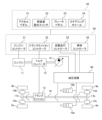
- the wheel loader 1 is roughly configured by an engine 11, a torque converter 12, a transmission 13, a brake 14, a hydraulic pump 15, a drive shaft 16, an axle shaft 17, an operating device 20, a control device 30, and a hydraulic circuit 40. ing.
- the engine 11 is, for example, a prime mover that generates driving force by burning fossil fuel.
- the torque converter 12 is connected to the output shaft of the engine 11 and the input shaft of the transmission 13, and adjusts the driving force transmitted from the engine 11 to the transmission 13. In other words, a part of the driving force of the engine 11 is transferred to the transmission 13. to communicate.
- the transmission 13 shifts the driving force of the engine 11 transmitted via the torque converter 12, and transmits the shifted driving force to the driving wheels (front wheels 5a, 5b and rear wheels 6a, 6b) via a drive shaft 16 and an axle shaft 17. ). Furthermore, the transmission 13 can be switched between a forward state in which the drive wheels are rotated in a direction to move the wheel loader 1 forward, and a backward state in which the drive wheels are rotated in a direction to move the wheel loader 1 backward.
- the brakes 14a, 14b, 14c, and 14d brake the rotation of the front wheels 5a, 5b and the rear wheels 6a, 6b.
- the brakes 14 are provided at four locations corresponding to each wheel in order to brake the front wheels 5a, 5b and the rear wheels 6a, 6b, respectively.
- the hydraulic pump 15 is connected to and driven by the output shaft of the engine 11.
- the hydraulic pump 15 uses the driving force transmitted from the engine 11 to forcefully feed hydraulic oil stored in a hydraulic oil tank (not shown) to the hydraulic circuit 40 .
- the hydraulic circuit 40 is composed of a directional switching valve and the like, and is discharged from the hydraulic pump 15 to operate the hydraulic actuator (brake 14, Controls the flow rate and direction of hydraulic oil supplied to the steering cylinders 10a, 10b).
- the operating device 20 operates the wheel loader 1 by outputting an operating signal to the control device 30 in accordance with an operator's operation, and includes, for example, an accelerator pedal 21, a forward/reverse direction switch 22, a brake pedal 23, and a steering wheel. It includes a wheel 24 and the like.
- the accelerator pedal 21 is used to adjust the rotation speed of the engine 11 according to the operator's operation.
- the accelerator pedal 21 outputs an operation signal indicating the amount of depression by the operator to the control device 30.
- the forward/backward direction instruction switch 22 is an alternate switch that indicates the traveling direction state of the wheel loader 1 according to an operation by the operator. For example, when the forward/reverse direction switch 22 is switched to the forward position, the transmission 13 is switched to the forward state. Furthermore, when the forward/reverse direction switch 22 is switched to the reverse position, the transmission 13 is switched to the reverse position. The forward/reverse direction switch 22 outputs an operation signal indicating the current position to the control device 30.
- the brake pedal 23 is used to adjust the braking force of the brake 14 according to the operator's operation.
- the brake pedal 23 outputs an operation signal indicating the amount of depression by the operator to the control device 30.
- the steering wheel 24 expands and contracts the steering cylinders 10a and 10b according to the operator's operations. For example, when the operator rotates the steering wheel 24 to the right (clockwise), the left steering cylinder 10a extends and the right steering cylinder 10b retracts, causing the front frame 2 to move relative to the rear frame 3. Bend to the right. On the other hand, when the operator rotates the steering wheel 24 to the left (rotating counterclockwise), the left steering cylinder 10a retracts and the right steering cylinder 10b extends, causing the front frame 2 to move relative to the rear frame 3. bends to the left.
- the steering wheel 24 outputs a rotation direction and an operation signal corresponding to the rotation direction to the control device 30.
- the control device 30 controls the operation of the wheel loader 1 based on operation signals output from the operation device 20 and detection signals output from various sensors described below.
- the control device 30 includes a CPU (Central Processing Unit), a ROM (Read Only Memory), and a RAM (Random Access Memory).
- the control device 30 realizes each functional block described later by having the CPU read and execute program codes stored in the ROM.
- the RAM is used as a work area when the CPU executes a program.
- the specific configuration of the control device 30 is not limited to this, and may be realized by other hardware.
- the control device 30 includes, for example, an engine controller 31, a transmission controller 32, a vehicle body controller 33, and an automatic driving controller 34.
- the engine controller 31, the transmission controller 32, and the vehicle body controller 33 may each be independent hardware, and may be connected to each other through a CAN (Controller Area Network) so that they can communicate with each other.
- the engine controller 31, the transmission controller 32, and the vehicle body controller 33 may be configured to be realized by each executing a program stored in a ROM using a CPU.
- the engine controller 31 increases or decreases the rotation speed of the engine 11 according to an operation signal indicating the amount of depression of the accelerator pedal 21.
- the transmission controller 32 switches the state of the transmission 13 between a forward state and a backward state in response to an operation signal indicating the position of the forward/reverse direction switch 22.
- the vehicle body controller 33 controls the braking force of the brake 14 in accordance with an operation signal indicating the amount of depression of the brake pedal 23 .
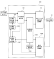
- FIG. 4 is a functional block diagram showing extracted functions of the automatic travel controller along with related components.
- the automatic travel controller 34 includes a reference point correction amount calculation section 101, a self-position calculation section 102, a target trajectory setting section 103, and a steering control command calculation section 104.
- the automatic travel controller 34 controls the automatic travel of the wheel loader 1 (including operator assistance), and controls the operation of the hydraulic circuit 40 based on the detection signal output from the self-position sensor 50. , controls operations of steering cylinders 10a, 10b, brakes 14a, 14b, 14c, 14d, etc.
- the self-position sensor 50 detects the self-position of the vehicle body of the wheel loader 1 and outputs it to the self-position calculation unit 102 as self-position information.
- the self-position sensor 50 is, for example, a GNSS (Global Navigation Satellite System), and outputs current latitude and longitude coordinates as a positioning result. Note that the self-position sensor 50 is not limited to this, and may be realized by other means.
- the self-position detected by the self-position sensor 50 is, for example, the position of a GNSS antenna installed on the wheel loader 1.
- the reference point correction amount calculation unit 101 calculates a reference point correction amount for correcting the self position detected by the self position sensor 50 to the position of the reference point set on the wheel loader 1, and calculates the calculated reference point correction amount. The amount is output to the self-position calculation unit 102.
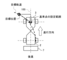
- FIGS. 5 and 6 are diagrams showing examples of setting reference points for the vehicle body.
- FIG. 5 shows an example of setting the reference points when moving forward
- FIG. 6 shows an example of setting the reference points when moving backward.
- a reference point is set at the center in the left-right direction of the frame (namely, the front frame 2) located at the front (on the traveling direction side). More specifically, the left and right centers of the axles (axle shafts 17a, 17b) of the wheels (front wheels 5a, 5b) of the frame (front frame 2) on the traveling direction side of the front frame 2 and rear frame 3 are relative to the axle.
- a reference point is set on a straight line 100 passing vertically in the front-rear direction, from the axle of the front wheels 5a, 5b to the tip of the bucket 7.
- a reference point is set at the center in the left-right direction of the frame (that is, the rear frame 3) located in the front (on the traveling direction side). More specifically, the left and right centers of the axles of the wheels (rear wheels 6a, 6b) of the frame (rear frame 3) on the traveling direction side of the front frame 2 and rear frame 3 are aligned perpendicularly to the axle in the front-rear direction.
- a reference point is set on the straight line 100 passing through, from the axle of the rear wheels 6a, 6b to the rear end (end on the traveling direction side) of the rear frame 3.
- the self-position calculation unit 102 calculates the position of the reference point at the work site (i.e. , the coordinate position in the work site coordinate system or the earth coordinate system) and outputs it to the steering control command calculation unit 104.
- the target trajectory setting unit 103 sets a target trajectory for the wheel loader 1 to travel, sets a target position on the target trajectory, and outputs it to the steering control command calculation unit 104.
- the target trajectory setting unit 103 forms a target trajectory by arranging a plurality of target coordinates in advance, for example, and outputs one target coordinate of the target trajectory as a target position. Note that the method of setting the target trajectory and target position by the target trajectory setting unit 103 is not limited to this, and may be realized using other methods.
- the steering control command calculation unit 104 calculates the bending angle of the vehicle body as a steering control amount based on the position of the reference point from the self-position calculation unit 102 and the target position from the target trajectory setting unit 103, and calculates the bending angle of the vehicle body as a steering control amount, and calculates the oil pressure as a control command.
- Output to circuit 40 That is, the control command output from the steering control command calculation unit 104 is a command for controlling the direction switching valve that controls the direction and flow rate of the hydraulic oil supplied to the steering cylinders 10a and 10b.
- the bending angle of the vehicle body is the amount of bending between the front frame 2 and the rear frame 3, and when the axles of the front wheels 5a, 5b and the axles of the rear wheels 6a, 6b are parallel, that is, the front frame 2 and the rear frame 3 become straight, the bending angle becomes 0 (zero).
- the calculation of the bending angle of the vehicle body by the steering control command calculation unit 104 is performed based on, for example, a straight line connecting the turning center position and the target position, and This is done by setting the angle formed by the straight line connecting the center position and the reference point position, that is, the angle at the turning center position, as the bending angle of the vehicle body.
- the method of calculating the bending angle by the steering control command calculation unit 104 is not limited to this, and may be realized using other methods.
- a straight line passing through the left and right center of the axle of the wheel of the frame on the traveling direction side among the front frame 2 and the rear frame 3 in the front and rear direction perpendicular to the axle A reference point for the wheel loader 1, which is an articulated vehicle, is set on the axle or on the side in the traveling direction of the axle, and the position of the reference point at the work site is calculated based on the detection result of the self-position sensor.
- the steering control amount which is the amount of bending of the front frame 2 with respect to the rear frame 3, is calculated based on a target trajectory predetermined as a travel trajectory and the position of a reference point at the work site.
- the distance from the left and right centers of the axles (axle shafts 17a, 17b) of the wheels of the frame (front frame 2 or rear frame 3) located on the traveling direction side (front) to the target trajectory is opposite to the traveling direction.
- the distance from the left and right center of the axle of the wheels of the frame (front frame 2 or rear frame 3) located on the side (rear) is less than or equal to the target trajectory, so the frame located on the side (front) in the direction of travel is on the target trajectory.
- the target trajectory can be followed without meandering. That is, it is possible to suppress meandering travel while improving the accuracy of following the target route.
- the wheel loader of this embodiment is configured to set the reference point of the wheel loader according to the direction of movement indicated by a forward/backward direction switch that is switched by the operator. Note that in this embodiment, the same components as those in the first embodiment are denoted by the same reference numerals, and the description thereof will be omitted.
- FIG. 7 is a functional block diagram showing extracted functions of the automatic travel controller according to the present embodiment together with related configurations.
- the automatic travel controller 34A includes a reference point switching section 505, a reference point correction amount calculation section 501, a self-position calculation section 102, a target trajectory setting section 103, and a steering control command calculation section 104.
- the reference point switching unit 505 receives the operation signal from the forward/reverse direction switch 22, determines whether the transmission 13 is in the forward or backward state, and outputs the determination result to the reference point correction amount calculation unit 501.
- FIG. 8 is a flowchart showing the processing contents of the reference point switching section.
- step S100 when the reference point switching unit 505 of the automatic travel controller 34A detects an operation signal from the forward/reverse direction switch 22 (step S100), the reference point switching unit 505 of the automatic travel controller 34A detects the operation signal from the forward/reverse direction switch 22 as a signal indicating the forward position. It is determined whether or not (step S110).
- step S110 If the determination result in step S110 is YES, the determination result that the transmission 13 is in the forward state is output to the reference point correction amount calculation unit 501 (step S120), and the process ends.
- step S110 determines whether the transmission 13 is in the reverse state is in the reverse state. If the determination result in step S110 is NO, the determination result that the transmission 13 is in the reverse state is output to the reference point correction amount calculation unit 501 (step S130), and the process ends.
- the reference point correction amount calculation unit 501 calculates the reference point correction amount according to the determination result from the reference point switching unit 505, that is, whether the transmission 13 is in the forward state or the backward state.
- the reference point correction amount is output to the self-position calculation section 102.
- FIG. 9 is a flowchart showing the processing contents of the reference point correction amount calculation section.
- the reference point correction amount calculation unit 501 of the automatic driving controller 34 first obtains the determination result from the reference point switching unit 505 (step S200), and determines whether the determination result indicates a forward state ( Step S210).
- step S210 If the determination result in step S210 is YES, the reference point correction amount when moving forward, that is, the left and right center of the axle of the front wheel 5 of the front frame 2 on the traveling direction side is The reference point correction amount for setting a reference point between the axle of the front wheel 5 and the tip of the bucket 7 on a straight line passing through the machine is output to the self-position calculation unit 102 (step S220), and the process is ended. .
- step S210 determines whether the determination result in step S210 is NO.
- the reference point correction amount when reversing that is, the left and right center of the axle of the rear wheel 6 of the rear frame 3 on the traveling direction side is adjusted perpendicularly to the axle.
- Self-position calculation of the reference point correction amount when setting a reference point between the axle of the rear wheel 6 and the rear end (end on the traveling direction side) of the rear frame 3 on a straight line passing in the front-rear direction 102 step S230
- the reference point is configured to be corrected (switched) in accordance with the operation of the forward/backward direction switch 22 by the operator, it is possible to more reliably improve the accuracy of following the target route while suppressing meandering travel. I can do it.
- the wheel loader of this embodiment sets the reference point of the wheel loader according to the detection result from the vehicle body information acquisition sensor that detects vehicle body information (acceleration direction) for detecting the traveling direction (forward, reverse) of the vehicle. It is configured to do so. Note that in this embodiment, the same components as those in the first and second embodiments are designated by the same reference numerals, and the description thereof will be omitted.
- FIG. 10 is a functional block diagram showing extracted functions of the automatic travel controller according to the present embodiment together with related configurations.
- the automatic travel controller 34B includes a reference point switching section 805, a reference point correction amount calculation section 501, a self-position calculation section 102, a target trajectory setting section 103, and a steering control command calculation section 104.
- the reference point switching unit 805 determines whether the transmission 13 is in the forward or backward state according to the detection result from the vehicle body information acquisition sensor 51, and outputs the determination result to the reference point correction amount calculation unit 501. .
- the vehicle body information acquisition sensor 51 is a device capable of detecting acceleration, such as an IMU (Inertial Measurement Unit), and when the wheel loader 1 is moving forward (that is, moving in the direction of the front frame 2
- the wheel loader 1 detects positive acceleration when moving backwards (that is, when moving backwards), and detects and outputs negative acceleration when moving backwards (that is, when moving in the direction of the rear frame 3).
- the configuration of the vehicle body information acquisition sensor 51 is not limited to this, and may be realized by other means.
- a sensor for detecting the traveling direction of the wheel loader 1 the following can be used depending on the type of traveling device.
- a rotation sensor built into the transmission may be used, or if the vehicle is an electric vehicle that runs with the driving force of an electric motor, a resolver of the electric motor may be used, or a hydraulic pump and If the HST vehicle is configured with a hydraulic motor, a tilt angle sensor for a hydraulic pump and a hydraulic motor may be used.
- a controller for the traveling device may be provided separately, and the traveling direction may be received from the controller for the traveling device.
- FIG. 11 is a flowchart showing the processing contents of the reference point switching section.
- the reference point switching unit 805 of the automatic driving controller 34A determines whether or not the acceleration that is the acquired detection result is positive. (Step S310).
- step S310 determines whether the acceleration is positive and it is determined that the wheel loader 1 is moving toward the front frame 2, it is determined that the transmission 13 is in the forward state.
- the result is output to the reference point correction amount calculation unit 501 (step S320), and the process ends.
- step S310 determines whether the transmission 13 is in the backward state. If the determination result in step S310 is NO, that is, if the acceleration is negative and it is determined that the wheel loader 1 is moving toward the rear frame 3, it is determined that the transmission 13 is in the backward state.
- the determination result is output to the reference point correction amount calculation unit 501 (step S330), and the process ends.
- the reference point correction amount calculation unit 501 calculates the reference point correction amount according to the determination result from the reference point switching unit 805, that is, whether the transmission 13 is in the forward or backward state, and calculates the calculation result.
- the reference point correction amount is output to the self-position calculation section 102.
- the reference point is configured to be corrected (switched) according to the detection result of the vehicle body information acquisition sensor 51 while the wheel loader 1 is running, it is possible to more reliably improve the tracking accuracy of the target route while also Running can be suppressed.
- the wheel loader of this embodiment sets the reference point of the wheel loader 1 according to the traveling direction determined based on the position of the reference point at the work site and the target position, and when the reference point is changed, the reference point is set as the reference point.
- the route plan is configured to be switched depending on the position of the point in the articulated vehicle. Note that in this embodiment, the same components as those in the first to third embodiments are designated by the same reference numerals, and the description thereof will be omitted.
- FIG. 12 is a functional block diagram showing extracted functions of the automatic travel controller according to the present embodiment together with related configurations.
- the automatic travel controller 34C includes a reference point switching unit 1005, a route plan setting unit 1006, a reference point switching determination unit 1007, a reference point correction amount calculation unit 501, a self-position calculation unit 102, a target position calculation unit 1003, and , a steering control command calculating section 104.
- the target position calculation unit 1003 calculates a target position based on the position of the reference point from the self-position calculation unit 102 and the route plan from the route plan setting unit 1006, and sends the calculation result to the steering control command calculation unit 104 and the reference point. It is output to the switching determination section 1007.
- FIG. 13 is a flowchart showing the processing contents of the target position calculation section.
- the target position calculation unit 1003 of the automatic driving controller 34C first obtains calculation results from the self-position calculation unit 102 and the route plan setting unit 1006 (step S400), and then calculates the reference point from the self-position calculation unit 102.
- the target position is calculated from the position of , and the target coordinates of the route plan from the route plan setting unit 1006 (step S410).
- the target position calculation unit 1003 calculates the target position by, for example, interpolating a route using a spline function based on the current reference point position and the current target coordinates, and then moving the interpolated route from the current reference point position to a constant position. This is done by setting the target position to the position traveled by a distance of .
- the method of calculating the target position is not limited to this, and may be realized using other methods.
- step S410 Upon completion of the process in step S410, the target position calculated in step S410 is subsequently output to the steering control command calculation unit 104 and reference point switching determination unit 1007 (step S420), and the process ends.
- the reference point switching unit 1005 receives the determination result from the reference point switching determination unit 1007 and determines whether the wheel loader 1 is in the forward or backward state. The determined result is output to the reference point correction amount calculation section 501. Note that the reference point switching determination unit 1007 determines whether the traveling direction of the wheel loader 1 has been switched based on the position of the reference point from the self-position calculation unit 102 and the target position from the target position calculation unit 1003. However, the progress state of the wheel loader 1 is output as a determination result, and details of the process will be described later.
- FIG. 14 is a flowchart showing the processing contents of the reference point switching section.
- the reference point switching unit 1005 of the automatic driving controller 34C acquires the determination result from the reference point switching determination unit 1007 (step S500), and determines whether the acquired determination result indicates a forward state. (Step S510).
- step S510 If the determination result in step S510 is YES, the determination result that the wheel loader 1 is in the forward state (in other words, the transmission 13 is in the forward state) is output to the reference point correction amount calculation unit 501 (step S520), the process ends.
- step S510 a determination result indicating that the wheel loader 1 is in the backward state (in other words, the transmission 13 is in the backward state) is output to the reference point correction amount calculation unit 501. (Step S530), the process ends.
- the route plan setting unit 1006 sets a route plan to be output to the target position calculation unit 1003 based on the determination result from the reference point switching unit 1005.
- the route plan output to the target position calculation unit 1003 sets a target trajectory on which the wheel loader 1 travels.
- the target trajectory is configured by sequentially arranging target coordinates from the start position to the target destination position.
- the route plan setting unit 1006 determines the target coordinates based on the position of the reference point, the route plan setting unit 1006 has different route plans for when the wheel loader 1 moves forward and when the wheel loader 1 uses different reference points.
- the route plan during forward movement is composed of target coordinates based on the reference point in the forward state
- the route plan during backward movement is composed of target coordinates based on the reference point in the backward state.
- the configuration of the route plan setting unit 1006 is not limited to this, and may be implemented by other means.
- FIG. 15 is a flowchart showing the processing contents of the route plan setting section.
- the route plan setting unit 1006 of the automatic driving controller 34C acquires the determination result from the reference point switching unit 1005 (step S600), and determines whether the acquired determination result indicates a forward state ( Step S610).
- step S610 If the determination result in step S610 is YES, the route plan corresponding to the reference point during forward movement of the wheel loader 1 is output to the target position calculation unit 1003 (step S520), and the process ends.
- step S610 a route plan corresponding to the reference point for the backward movement of the wheel loader is output to the target position calculation unit 1003 (step S630), and the process ends.
- the reference point switching determining unit 1007 determines whether to switch the traveling direction of the wheel loader 1 based on the position of the reference point from the self-position calculating unit 102 and the target position from the target position calculating unit 1003, and outputs the determination result. It is output to the reference point switching unit 1005. For example, when the initial state is the forward state, when the traveling direction of the wheel loader 1 is switched, a determination result indicating switching to the backward state is output to the reference point switching unit 1005. At this time, until the switching of the traveling direction of the wheel loader 1 is determined, the determination result indicating the forward state is output to the reference point switching unit 1005.
- the specific configuration of the reference point switching determination section 1007 is not limited to this, and may be implemented by other means.
- FIG. 16 is a flowchart showing the processing contents of the reference point switching determination section.
- the reference point switching determination unit 1007 of the automatic travel controller 34C acquires the calculation results from the self-position calculation unit 102 and the target position calculation unit 1003 (step S700), and based on the acquired calculation results, A vector from the current reference point position to the target position is calculated (step S710), and a vector from the current reference point position to the previous reference point position at the work site is calculated (step S720).
- step S730 it is determined whether the angle formed by the vectors calculated in steps S710 and S720 is 90 degrees or more (step S730), and if the determination result is YES, the previous traveling direction state (forward state or backward state) is determined (step S730).
- the determination result indicating the state) is output to the reference point switching unit 1005 (step S740), the current position of the reference point and the traveling direction state at the work site are recorded (step S760), and the process ends.
- the recorded current reference point position and traveling direction state are used as the previous reference point position and traveling direction state during the next determination process in the reference point switching determination unit 1007.
- step S750 it is determined whether the previous traveling direction state is a forward state (step S750). If the determination result in step S750 is YES, the determination result indicating the backward state is output to the reference point switching unit 1005 (step S751), and the process proceeds to step S760. If the determination result in step S750 is NO, the determination result indicating the forward state is output to the reference point switching unit 1005 (step S752), and the process proceeds to step S760.
- the configuration is configured so that the reference point correction amount is switched according to the route plan and the position of the reference point, the reference point in the wheel loader 1 is automatically corrected according to the traveling direction, and the target route can be more reliably reached. Meandering travel can be suppressed while improving tracking accuracy.
- the distance between the target position and the position of the reference point at the work site is the same as the distance between the target position before the change of the reference point and the position of the reference point.
- the speed control amount which is the target running speed of the wheel loader at the work site, is calculated and braked so that the distance from the position at the work site is less than or equal to the distance from the position at the work site.
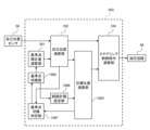
- FIG. 17 is a functional block diagram showing extracted functions of the automatic travel controller according to the present embodiment together with related configurations.
- the automatic travel controller 34D includes a reference point switching unit 1005, a reference point correction amount calculation unit 1501, a route planning setting unit 1506, a reference point switching determination unit 1507, a speed control command calculation unit 1508, a self-position calculation unit 102, It has a target position calculation section 1003 and a steering control command calculation section 104.
- the reference point correction amount calculation unit 1501 calculates the reference point correction amount according to the determination result from the reference point switching unit 1005, that is, whether the wheel loader 1 (in other words, the transmission 13) is in the forward or backward state. is calculated, and the reference point correction amount, which is the calculation result, is output to the self-position calculation unit 102.
- FIG. 18 is a flowchart showing the processing contents of the reference point correction amount calculation section.
- the reference point correction amount calculation unit 1501 of the automatic driving controller 34D first obtains the determination result from the reference point switching unit 1005 (step S800), and determines whether the determination result indicates a forward state ( Step S810).
- step S810 If the determination result in step S810 is YES, the reference point correction amount when moving forward, that is, the left and right center of the axle of the front wheel 5 of the front frame 2 on the traveling direction side is The reference point correction amount for setting a reference point between the axle of the front wheel 5 and the tip of the bucket 7 on a straight line passing through the CPU is output to the self-position calculation unit 102 (step S820), and the process ends. .
- step S810 determines whether the determination result in step S810 is NO.
- the reference point correction amount when reversing that is, the left and right center of the axle of the rear wheel 6 of the rear frame 3 on the traveling direction side is adjusted perpendicularly to the axle.
- Self-position calculation of the reference point correction amount when setting a reference point between the axle of the rear wheel 6 and the rear end (end on the traveling direction side) of the rear frame 3 on a straight line passing in the front-rear direction 102 step S830
- the route plan setting unit 1506 outputs the route plan to the target position calculation unit 1003.
- the route plan output to the target position calculation unit 1003 sets a target trajectory on which the wheel loader 1 travels.
- the target trajectory is configured by sequentially arranging target coordinates from the start position to the target destination position.
- the specific configuration of the route plan setting unit 1506 is not limited to this, and may be realized by other means.
- the reference point switching determination unit 1507 determines whether to switch the traveling direction of the wheel loader 1 based on the position of the reference point from the self-position calculation unit 102 and the target position from the target position calculation unit 1003, and outputs the determination result. It is output to the reference point switching unit 1005. For example, when the initial state is the forward state, when the traveling direction of the wheel loader 1 is switched, a determination result indicating switching to the backward state is output to the reference point switching unit 1005. At this time, until the switching of the traveling direction of the wheel loader 1 is determined, the determination result indicating the forward state is output to the reference point switching unit 1005.
- the specific configuration of the reference point switching determination section 1507 is not limited to this, and may be implemented by other means.
- FIG. 19 is a flowchart showing the processing contents of the reference point switching determination section.
- the reference point switching determination unit 1507 of the automatic travel controller 34D acquires the calculation results from the self-position calculation unit 102 and the target position calculation unit 1003 (step S900), and based on the acquired calculation results, A vector from the current reference point position to the target position is calculated (step S910), and a vector from the current reference point position to the previous reference point position at the work site is calculated (step S920).
- step S930 it is determined whether the angle formed by the vectors calculated in steps S910 and S920 is 90 degrees or more (step S930), and if the determination result is YES, the previous direction of travel state (forward state or backward state) is determined (step S930).
- the determination result indicating the status) is output to the reference point switching unit 1005 (step S940), the current position of the reference point and the traveling direction status at the work site are recorded (step S960), and the process ends.
- the recorded current reference point position and traveling direction state are used as the previous reference point position and traveling direction state during the next determination process in the reference point switching determination unit 1507.
- step S950 it is determined whether the previous traveling direction state is a forward state (step S950). If the determination result in step S950 is YES, the determination result indicating that the traveling direction state has been switched is output to the speed control command calculation unit 1508, and the determination result indicating the backward state is output to the reference point switching unit 1005. It is output (step S951), and the process proceeds to step S960. Further, if the determination result in step S950 is NO, the determination result indicating that the traveling direction state has not been switched is output to the speed control command calculation unit 1508, and the determination result indicating the forward direction state is output to the reference point switching. 1005 (step S952), and the process proceeds to step S960.
- the speed control command calculation unit 1508 controls the vehicle body based on the position of the reference point from the self-position calculation unit 102, the target position from the target position calculation unit 1003, and the determination result from the reference point switching determination unit 1507. It determines whether it is necessary to control the power, calculates a necessary control command, and outputs it to the hydraulic circuit 40. For example, if the brake 14 is configured to brake the rotation of the drive wheels by sandwiching a brake disc that rotates integrally with each drive wheel between a pair of brake shoes, the control command output to the hydraulic circuit 40 may be applied to the brake disc. This is a control command for the valve that supplies hydraulic oil to the brake shoes that sandwich the brake.
- the specific configurations of the speed control command calculation unit 1508 and the brake 14 are not limited to this, and may be realized by other means.
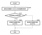
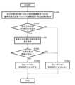
- FIG. 20 is a flowchart showing the processing contents of the speed control command calculation section.
- the speed control command calculation unit 1508 of the automatic travel controller 34D obtains calculation results and determination results from the self-position calculation unit 102, the target position calculation unit 1003, and the reference point switching determination unit 1507 (step S1000), It is determined whether the determination result indicates that the traveling direction state has changed (step S1010).
- step S1010 the difference between the position of the reference point acquired from the self-position calculation unit 102 and the target position acquired from the target position calculation unit 1003 is calculated (step S1020), and the difference in position is It is determined whether or not it is less than or equal to a predetermined threshold (step S1030).
- the threshold value is set to a value such as 1 m, for example.
- a table of correction distances for the difference between the reference point position and the target position may be prepared in advance according to other characteristics, and the threshold value may be determined based on this table.
- step S1030 If the determination result in step S1030 is NO, a command is output to the hydraulic circuit 40 as a control command for the brake 14 to control the valve so as to supply hydraulic fluid that causes the brake shoes to sandwich the brake disc ( Step S1040), the process ends.
- the amount by which the brake disc is held between the brake shoes is, for example, approximately half the amount by which the brake pedal 23 is depressed.
- step S1010 determines whether the control command for the brake 14 is not output (step S1050), and the process ends.
- the target trajectory can be followed using the center of the bucket 7 from the left and right as the reference point for self-position, and if the reference point changes and the error with the target trajectory becomes large. Since the vehicle can run with the braking force of the brake 14 applied until the error is absorbed, sudden movements of the wheel loader 1 caused by changes in the reference point caused by switching between forward and reverse modes can be suppressed, making it more reliable. It is possible to suppress meandering travel while improving the accuracy of following the target route.
- the present invention is not limited to the above-described embodiments, and includes various modifications and combinations within the scope of the invention. Furthermore, the present invention is not limited to having all the configurations described in the above embodiments, but also includes configurations in which some of the configurations are deleted. Moreover, each of the above-mentioned configurations, functions, etc. may be realized in part or in whole by, for example, designing an integrated circuit. Furthermore, each of the above configurations, functions, etc. may be realized by software by a processor interpreting and executing a program for realizing each function.
- Vehicle body information acquisition sensor 100... Straight line, 101... Reference point correction amount calculation section, 102... Self-position calculation section, 103... Target trajectory setting section, 104... Steering control command calculation section, 501... Reference point correction amount calculation section , 505... Reference point switching section, 805... Reference point switching section, 1003... Target position calculation section, 1005... Reference point switching section, 1006... Route plan setting section, 1007... Reference point switching determination section, 1501... Reference point correction amount Calculation unit, 1506...Route plan setting unit, 1507...Reference point switching determination unit, 1508...Speed control command calculation unit
Landscapes
- Engineering & Computer Science (AREA)
- Automation & Control Theory (AREA)
- Mechanical Engineering (AREA)
- Transportation (AREA)
- Combustion & Propulsion (AREA)
- Chemical & Material Sciences (AREA)
- Structural Engineering (AREA)
- General Engineering & Computer Science (AREA)
- Civil Engineering (AREA)
- Mining & Mineral Resources (AREA)
- Remote Sensing (AREA)
- Physics & Mathematics (AREA)
- General Physics & Mathematics (AREA)
- Radar, Positioning & Navigation (AREA)
- Aviation & Aerospace Engineering (AREA)
- Operation Control Of Excavators (AREA)
- Non-Deflectable Wheels, Steering Of Trailers, Or Other Steering (AREA)
Priority Applications (4)
| Application Number | Priority Date | Filing Date | Title |
|---|---|---|---|
| KR1020247030764A KR20240152877A (ko) | 2022-03-24 | 2023-03-03 | 아티큘레이트식 차량 |
| US18/848,186 US20250207361A1 (en) | 2022-03-24 | 2023-03-03 | Articulated Vehicle |
| EP23774460.2A EP4501747A1 (en) | 2022-03-24 | 2023-03-03 | Articulated vehicle |
| CN202380027565.6A CN119072429A (zh) | 2022-03-24 | 2023-03-03 | 铰接式车辆 |
Applications Claiming Priority (2)
| Application Number | Priority Date | Filing Date | Title |
|---|---|---|---|
| JP2022-047809 | 2022-03-24 | ||
| JP2022047809A JP2023141474A (ja) | 2022-03-24 | 2022-03-24 | アーティキュレート式車両 |
Publications (1)
| Publication Number | Publication Date |
|---|---|
| WO2023181861A1 true WO2023181861A1 (ja) | 2023-09-28 |
Family
ID=88100682
Family Applications (1)
| Application Number | Title | Priority Date | Filing Date |
|---|---|---|---|
| PCT/JP2023/008140 WO2023181861A1 (ja) | 2022-03-24 | 2023-03-03 | アーティキュレート式車両 |
Country Status (6)
Cited By (1)
| Publication number | Priority date | Publication date | Assignee | Title |
|---|---|---|---|---|
| WO2025158829A1 (ja) * | 2024-01-24 | 2025-07-31 | 株式会社小松製作所 | 作業機械の制御システム及び作業機械の制御方法 |
Families Citing this family (1)
| Publication number | Priority date | Publication date | Assignee | Title |
|---|---|---|---|---|
| CN119384949A (zh) * | 2025-01-06 | 2025-02-07 | 宁波翠科机械有限公司 | 一种乘坐式割草机 |
Citations (3)
| Publication number | Priority date | Publication date | Assignee | Title |
|---|---|---|---|---|
| JPH06298374A (ja) * | 1993-04-12 | 1994-10-25 | Komatsu Ltd | 材料移載システムにおける材料投下高さ位置制御装置 |
| JP2017204089A (ja) | 2016-05-10 | 2017-11-16 | 大成建設株式会社 | 自律走行用制御装置および自律走行方法 |
| JP2020030625A (ja) * | 2018-08-23 | 2020-02-27 | 酒井重工業株式会社 | 建設車両の自律走行制御装置 |
-
2022
- 2022-03-24 JP JP2022047809A patent/JP2023141474A/ja active Pending
-
2023
- 2023-03-03 US US18/848,186 patent/US20250207361A1/en active Pending
- 2023-03-03 KR KR1020247030764A patent/KR20240152877A/ko active Pending
- 2023-03-03 WO PCT/JP2023/008140 patent/WO2023181861A1/ja active Application Filing
- 2023-03-03 EP EP23774460.2A patent/EP4501747A1/en active Pending
- 2023-03-03 CN CN202380027565.6A patent/CN119072429A/zh active Pending
Patent Citations (3)
| Publication number | Priority date | Publication date | Assignee | Title |
|---|---|---|---|---|
| JPH06298374A (ja) * | 1993-04-12 | 1994-10-25 | Komatsu Ltd | 材料移載システムにおける材料投下高さ位置制御装置 |
| JP2017204089A (ja) | 2016-05-10 | 2017-11-16 | 大成建設株式会社 | 自律走行用制御装置および自律走行方法 |
| JP2020030625A (ja) * | 2018-08-23 | 2020-02-27 | 酒井重工業株式会社 | 建設車両の自律走行制御装置 |
Cited By (1)
| Publication number | Priority date | Publication date | Assignee | Title |
|---|---|---|---|---|
| WO2025158829A1 (ja) * | 2024-01-24 | 2025-07-31 | 株式会社小松製作所 | 作業機械の制御システム及び作業機械の制御方法 |
Also Published As
| Publication number | Publication date |
|---|---|
| US20250207361A1 (en) | 2025-06-26 |
| CN119072429A (zh) | 2024-12-03 |
| EP4501747A1 (en) | 2025-02-05 |
| KR20240152877A (ko) | 2024-10-22 |
| JP2023141474A (ja) | 2023-10-05 |
Similar Documents
| Publication | Publication Date | Title |
|---|---|---|
| WO2023181861A1 (ja) | アーティキュレート式車両 | |
| JP7139019B2 (ja) | 建設車両の自律走行制御装置 | |
| US11292521B2 (en) | Autonomous driving control device and autonomous driving path computation method | |
| EP3900505B1 (en) | Control device for automatic travel work vehicle | |
| EP4218379A1 (en) | Automatic traveling system, automatic traveling method, and automatic traveling program | |
| KR20190056964A (ko) | 자동 운전 시스템 | |
| JP2019055644A (ja) | 車両制御装置、車両制御方法および車両制御システム | |
| JP2020028243A (ja) | 作業車両用の自動走行システム | |
| JP2021169291A (ja) | 車両の運転支援装置。 | |
| JP6818696B2 (ja) | 作業車両の制御システム、方法、及び作業車両 | |
| KR20230175288A (ko) | 대형 차량을 위한 적응형 경로 추적 알고리즘 | |
| WO2022209465A1 (ja) | システム、方法および作業車両 | |
| JP2019137283A (ja) | 運転支援装置、運転支援方法及び運転支援システム | |
| WO2020183988A1 (ja) | 作業車両 | |
| JP2019053470A (ja) | 作業車両用の自律走行システム | |
| JP7346754B2 (ja) | ダンプトラックの制御システム | |
| JP7386757B2 (ja) | 作業車両の自律走行システム | |
| WO2024089987A1 (ja) | 作業機械及び作業機械を制御するための方法 | |
| JP2024136838A (ja) | 作業機械 | |
| JP7602614B2 (ja) | 車両制御装置、車両制御方法、および車両制御システム | |
| US20240247466A1 (en) | Work machine and method for controlling work machine | |
| WO2023286443A1 (ja) | 作業機械、及び、作業機械を制御するための方法 | |
| US12392110B2 (en) | Work machine and method for controlling work machine | |
| WO2023053700A1 (ja) | 作業機械を制御するためのシステムおよび方法 | |
| CN117950401B (zh) | 车辆避障控制方法、装置、设备及存储介质 |
Legal Events
| Date | Code | Title | Description |
|---|---|---|---|
| 121 | Ep: the epo has been informed by wipo that ep was designated in this application |
Ref document number: 23774460 Country of ref document: EP Kind code of ref document: A1 |
|
| ENP | Entry into the national phase |
Ref document number: 20247030764 Country of ref document: KR Kind code of ref document: A |
|
| WWE | Wipo information: entry into national phase |
Ref document number: 1020247030764 Country of ref document: KR |
|
| WWE | Wipo information: entry into national phase |
Ref document number: 202380027565.6 Country of ref document: CN |
|
| WWE | Wipo information: entry into national phase |
Ref document number: 18848186 Country of ref document: US |
|
| WWE | Wipo information: entry into national phase |
Ref document number: 2023774460 Country of ref document: EP |
|
| NENP | Non-entry into the national phase |
Ref country code: DE |
|
| ENP | Entry into the national phase |
Ref document number: 2023774460 Country of ref document: EP Effective date: 20241024 |
|
| WWP | Wipo information: published in national office |
Ref document number: 18848186 Country of ref document: US |