WO2023181608A1 - 熱音変換器 - Google Patents
熱音変換器 Download PDFInfo
- Publication number
- WO2023181608A1 WO2023181608A1 PCT/JP2023/001456 JP2023001456W WO2023181608A1 WO 2023181608 A1 WO2023181608 A1 WO 2023181608A1 JP 2023001456 W JP2023001456 W JP 2023001456W WO 2023181608 A1 WO2023181608 A1 WO 2023181608A1
- Authority
- WO
- WIPO (PCT)
- Prior art keywords
- flow path
- fluid
- sound wave
- heat storage
- storage device
- Prior art date
- Legal status (The legal status is an assumption and is not a legal conclusion. Google has not performed a legal analysis and makes no representation as to the accuracy of the status listed.)
- Ceased
Links
Images









Classifications
-
- F—MECHANICAL ENGINEERING; LIGHTING; HEATING; WEAPONS; BLASTING
- F03—MACHINES OR ENGINES FOR LIQUIDS; WIND, SPRING, OR WEIGHT MOTORS; PRODUCING MECHANICAL POWER OR A REACTIVE PROPULSIVE THRUST, NOT OTHERWISE PROVIDED FOR
- F03G—SPRING, WEIGHT, INERTIA OR LIKE MOTORS; MECHANICAL-POWER PRODUCING DEVICES OR MECHANISMS, NOT OTHERWISE PROVIDED FOR OR USING ENERGY SOURCES NOT OTHERWISE PROVIDED FOR
- F03G7/00—Mechanical-power-producing mechanisms, not otherwise provided for or using energy sources not otherwise provided for
- F03G7/002—Mechanical-power-producing mechanisms, not otherwise provided for or using energy sources not otherwise provided for using the energy of vibration of fluid columns
-
- H—ELECTRICITY
- H04—ELECTRIC COMMUNICATION TECHNIQUE
- H04R—LOUDSPEAKERS, MICROPHONES, GRAMOPHONE PICK-UPS OR LIKE ACOUSTIC ELECTROMECHANICAL TRANSDUCERS; ELECTRIC HEARING AIDS; PUBLIC ADDRESS SYSTEMS
- H04R23/00—Transducers other than those covered by groups H04R9/00 - H04R21/00
-
- F—MECHANICAL ENGINEERING; LIGHTING; HEATING; WEAPONS; BLASTING
- F02—COMBUSTION ENGINES; HOT-GAS OR COMBUSTION-PRODUCT ENGINE PLANTS
- F02G—HOT GAS OR COMBUSTION-PRODUCT POSITIVE-DISPLACEMENT ENGINE PLANTS; USE OF WASTE HEAT OF COMBUSTION ENGINES; NOT OTHERWISE PROVIDED FOR
- F02G5/00—Profiting from waste heat of combustion engines, not otherwise provided for
- F02G5/02—Profiting from waste heat of exhaust gases
Definitions
- thermosonic transducer The present disclosure relates to a thermosonic transducer.
- thermoacoustic converter converts heat into sound waves using thermoacoustic phenomena.
- the sound waves produced by the thermosonic transducer are further converted into other energy such as electricity and used.
- a heater which is a heat exchanger on the heating side, is placed at one end of a heat storage device through which the working fluid passes as a sound wave
- a heater which is a heat exchanger on the cooling side, is placed at the other end of the heat storage device.
- a temperature difference generated at both ends of the heat storage device by the fluid flowing through the heater and the fluid flowing through the cooler is used to amplify the sound waves of the working fluid passing through the heat storage device.
- thermosonic conversion efficiency in thermosonic converters, it is important to effectively exchange heat between the fluid and working fluid in the heater and between the fluid and working fluid in the cooler.
- a heat conductive member is arranged in the center of the high temperature part of the heat exchanger, and not only heat is supplied from the outer periphery of the high temperature part of the heat exchanger to the working fluid, but also heat is Heat is supplied from the central part of the hot section of the heat exchanger to the working fluid via the conductive member. This increases the efficiency of converting thermal energy into acoustic energy of sound waves.
- the temperature of the fluid supplied to the heater decreases by heating the working fluid, and the temperature of the fluid supplied to the cooler increases by cooling the working fluid. That is, in a heater, the temperature at the inlet where the fluid flows is the highest, and in the cooler, the temperature at the inlet where the fluid flows is the lowest.
- thermoacoustic converters, thermoacoustic devices, and the like do not take into account the influence of heat distribution in the heater and cooler on heat transfer to the heat storage device. Therefore, further efforts are required to more effectively increase thermosonic conversion efficiency.
- An object of the present disclosure is to provide a thermosonic converter that can more effectively increase thermosonic conversion efficiency by utilizing heat distribution in a heater and a cooler.
- thermoacoustic converter that converts heat into sound waves using thermoacoustic phenomena, a heater formed with a first sound wave passage through which the sound wave passes, and a high temperature side flow passage through which a first fluid flows around the first sound wave passage; a cooler formed with a second sound wave passage through which the sound wave passes, and a low-temperature side flow passage through which a second fluid having a temperature lower than the first fluid flows around the second sound wave passage; a heat storage device disposed between the heater and the cooler, and in which an intermediate sound wave passage connecting the first sound wave passage and the second sound wave passage is formed;
- the specific flow path has a structure in which the specific fluid flows from an inner position close to the heat accumulator to an outer position far from the heat accumulator in an axial direction parallel to the central axis of the heat accumulator.
- the flow path is formed in at least one of the heater and the cooler.
- the specific flow path which is at least one of the high temperature side flow path and the low temperature side flow path, ranges from an inner position close to the heat storage device to a position far from the heat storage device in the axial direction parallel to the central axis of the heat storage device. It has a structure in which a specific fluid flows toward an outer position.
- At least one of the hottest part of the heater and the coldest part of the cooler can be made to face the heat storage device.
- at least one of heat transfer from the heater to the heat storage device and heat transfer from the heat storage device to the cooler can be effectively performed.
- thermosonic conversion efficiency can be more effectively increased by utilizing the heat distribution in at least one of the heater and the cooler.
- FIG. 1 is an explanatory diagram showing a loop-type thermoacoustic power generation device according to Embodiment 1
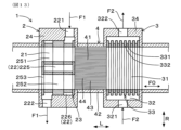
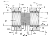
- FIG. 2 is an explanatory diagram showing a thermosonic converter according to Embodiment 1
- FIG. 3 is a cross-sectional view taken along line III-III in FIG. 2, showing the thermosonic converter according to Embodiment 1
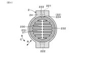
- FIG. 4 is a cross-sectional view taken along line IV-IV in FIG. 2, showing the thermosonic transducer according to Embodiment 1
- FIG. 5 is a sectional view taken along the line VV in FIG.
- FIG. 6 is a sectional view taken along line VI-VI in FIG. 3, showing the thermosonic converter according to Embodiment 1;
- FIG. 7 is an explanatory diagram showing a straight pipe type thermoacoustic power generation device according to Embodiment 1
- FIG. 8 is an explanatory diagram showing another thermosonic converter according to Embodiment 1
- FIG. 9 is an explanatory diagram showing a thermosonic converter according to Embodiment 2
- FIG. 10 is a sectional view taken along line XX in FIG. 9, showing a thermosonic converter according to Embodiment 2
- FIG. 11 is a sectional view taken along line XI-XI in FIG.
- FIG. 12 is a cross-sectional view taken along line XII-XII in FIG. 9, showing a thermosonic transducer according to Embodiment 2;
- FIG. 13 is a cross-sectional view taken along line XIII-XIII in FIG. 10, showing a thermosonic converter according to Embodiment 2;
- FIG. 14 is an explanatory diagram showing another thermosonic converter according to the second embodiment,
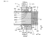
- FIG. 15 is an explanatory diagram showing a thermosonic converter according to Embodiment 3,
- FIG. 16 is a cross-sectional view taken along line XVI-XVI in FIG. 15, showing a thermosonic converter according to Embodiment 3;
- FIG. 16 is a cross-sectional view taken along line XVI-XVI in FIG. 15, showing a thermosonic converter according to Embodiment 3;
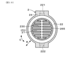
- FIG. 17 is a cross-sectional view taken along line XVII-XVII in FIG. 15, showing a thermosonic converter according to Embodiment 3;
- FIG. 18 is a cross-sectional view taken along line XVIII-XVIII in FIG. 9, showing a thermosonic converter according to Embodiment 3;
- FIG. 19 is an explanatory diagram showing a thermosonic converter according to Embodiment 4,
- FIG. 20 is a cross-sectional view taken along line XX-XX in FIG. 19, showing the thermosonic converter according to Embodiment 4,
- FIG. 21 is an explanatory diagram showing another thermosonic converter according to the fourth embodiment.
- thermosonic converter 1 converts heat into sound waves using thermoacoustic phenomena.
- the thermosonic converter 1 includes a heater 2 which is a heat exchanger on the heating side, a cooler 3 which is a heat exchanger on the cooling side, and a heat storage device 4.
- the heater 2 has a first sound wave passage 21 through which sound waves pass, and a high temperature side flow path 22 through which the first fluid F1 flows around the first sound wave passage 21.
- the cooler 3 has a second sound wave passage 31 through which sound waves pass, and a low temperature side flow passage 32 through which a second fluid F2 having a lower temperature than the first fluid F1 flows around the second sound wave passage 31.
- the heat storage device 4 is arranged between the heater 2 and the cooler 3, and has an intermediate sound wave passage 41 that connects the first sound wave passage 21 and the second sound wave passage 31.
- the high-temperature side flow path 22 of the heater 2 ranges from a position L1 on the inside near the heat storage 4 to a position L2 on the outside far from the heat storage 4 in the axial direction L parallel to the central axis O of the heat storage 4 and the heater 2. It has a structure in which the first fluid F1 flows toward.
- the high temperature side flow path 22 includes an axial flow path portion 224 in which the first fluid F1 flows from the inside L1 to the outside L2 in the axial direction L, and an axial flow path portion 224 in which the first fluid F1 flows in a direction perpendicular to the axial direction L.
- a circumferential flow path portion 223 is formed as a flowing orthogonal flow path portion.
- the high temperature side flow path 22 constitutes a specific flow path, and the first fluid F1 is the specific fluid.
- thermosonic converter 1 of this embodiment will be explained in detail below.
- the thermoacoustic converter 1 of this embodiment constitutes a thermoacoustic power generation device 5 that generates power using sound waves.
- One or more thermoacoustic converters 1 are disposed in the middle of the piping that constitutes the thermoacoustic power generation device 5 .
- the thermoacoustic power generation device 5 of this embodiment includes an annular pipe 51, a thermoacoustic converter 1 disposed in the middle of the annular pipe 51, and a power generation unit connected to a branch pipe 52 branched from the annular pipe 51. It is of a loop type and includes a machine 53.
- thermosonic transducer 1 is used to amplify the sound waves generated by the working fluid F0 circulating in the annular pipe 51.
- the thermosonic transducer 1 amplifies the sound waves caused by the working fluid F0 by expanding and contracting the working fluid F0, which is a gas, using the temperature difference between both ends of the heat storage device 4.
- the generator 53 is constituted by a linear generator that converts vibrations caused by sound waves into electricity using electromagnetic induction.
- the sound waves amplified by the thermosonic converter 1 are used by the generator 53 and converted into electricity.
- the thermoacoustic power generation device 5 includes a straight pipe 54, which is a pipe formed in a straight line, a thermoacoustic converter 1 disposed in the middle of the straight pipe 54, and a straight pipe 54, which is a pipe formed in a straight line.
- a straight pipe type may be used, which includes a sonic wave generator 55 connected to one end and a generator 53 connected to the other end of the straight pipe 54.
- the first fluid F1 of this embodiment utilizes the exhaust heat of the exhaust gas G supplied from the exhaust heat source 6.
- the first fluid F1 is a thermal oil that exchanges heat with the exhaust gas G discharged from the exhaust heat source 6 to the exhaust pipe 61 and is heated by the exhaust heat of the exhaust gas G.
- a heat exchanger 62 is disposed in the exhaust pipe 61 for exchanging heat between exhaust gas and heat transfer oil.
- the exhaust heat source 6 includes, for example, a firing furnace as an industrial furnace that heats by burning fuel, an aluminum melting furnace, and the like.
- the exhaust heat source 6 may be various types of equipment that discharge exhaust gas G from combustion. Circulating water used in a factory is used as the second fluid F2 in this embodiment. Various fluids having a temperature lower than that of the exhaust gas G may be used as the second fluid F2. Further, the temperature of the second fluid F2 is lower than the temperature of the working fluid F0.
- An inert gas such as helium or argon is used as the working fluid F0 of the thermoacoustic converter 1 and the thermoacoustic power generation device 5 of this embodiment.
- the direction along the central axis O of the heat storage device 4 is referred to as the axial direction L
- the direction around the central axis O of the heat storage device 4 is referred to as the circumferential direction C
- the direction along the central axis O of the heat storage device 4 is referred to as the circumferential direction C.
- the radial direction where R is the radial direction is called the radial direction R.
- the central axis O of the heater 2 and the central axis O of the cooler 3 are on the same axis as the central axis O of the regenerator 4, and the central axis O of the regenerator 4 is on the same axis as the central axis O of the heater 2 and the cooler
- the central axis O of No. 3 is also shown.
- the heat storage device 4 has an outer circumferential wall 42 constituting an outer circumferential wall, and a plurality of through holes 43 along the axial direction L on the inner circumferential side of the outer circumferential wall 42. It has a cell wall part 44.
- the outer peripheral wall portion 42 is formed into a cylindrical shape.
- the cell wall portion 44 is formed as a polygonal wall portion such as a lattice shape or a honeycomb shape.
- the heat storage device 4 is made of ceramic material.
- the heat storage device 4 may be made of a metal material.
- the intermediate sound wave passage 41 of the heat storage device 4 is formed by a plurality of through holes 43 surrounded by the cell wall portion 44 and the outer peripheral wall portion 42 .
- the heater 2 includes a first inner circumferential member 23 in which the first sound wave passage 21 is formed through in the axial direction L, and a first inner circumferential member 23 inside. and the first outer circumferential side member 24 that is housed therein.
- the first outer peripheral side member 24 forms a high temperature side flow path 22 between it and the first inner peripheral side member 23, and the first flow path inlet 221 through which the first fluid F1 flows into the high temperature side flow path 22. and a first flow path outlet 222 through which the first fluid F1 flows out from the high temperature side flow path 22.
- the first flow passage inlet 221 is formed at a position L1 inside the axial direction L close to the heat storage device 4, and the first flow passage outlet 222 is formed at a position in the axial direction far from the heat storage unit 4. It is formed at a position L2 outside L. Further, in the first outer circumferential member 24, the first flow path inlet 221 and the first flow path outlet 222 are formed at positions whose phases differ by 180° in the circumferential direction C.
- the cooler 3 includes a second inner circumferential member 33 in which a second sound wave passage 31 is formed through in the axial direction L, and a second outer circumferential member 34 that accommodates the second inner circumferential member 33 therein. It is configured.
- the second outer circumference side member 34 forms a low temperature side flow path 32 between it and the second inner circumference side member 33, and a second flow path inlet 321 through which the second fluid F2 flows into the low temperature side flow path 32. and a second flow path outlet 322 through which the second fluid F2 flows out from the low temperature side flow path 32.
- the second flow path inlet 321 and the second flow path outlet 322 are formed at intermediate positions in the axial direction L. Further, in the second outer circumferential member 34, the second flow path inlet 321 and the second flow path outlet 322 are formed at positions whose phases differ by 180° in the circumferential direction C.
- the high temperature side flow path 22 as the specific flow path of this embodiment includes a circumferential flow path portion 223 along the circumferential direction C and an axial flow path portion along the axial direction L. 224 are alternately formed in the axial direction L.
- the circumferential flow path portion 223 is formed as an orthogonal flow path portion.
- the circumferential flow path portion 223 is formed in an annular shape on the outer peripheral side of the first sound wave path 21 .
- the axial flow path portion 224 is formed to penetrate in the axial direction L on the outer peripheral side of the first sound wave path 21 .
- the axial flow path portions 224 adjacent to each other are formed apart from a specific position in the circumferential direction C and a position whose phase differs by 180 degrees from the specific position.
- the first inner circumferential member 23 of the heater 2 is formed by laminating a plurality of laminated plates 231 and 232 having different external shapes.
- the first outer peripheral member 24 of the heater 2 is formed into a container shape that accommodates the first inner peripheral member 23 .
- the laminated plates 231 and 232 constituting the first inner circumference side member 23 include a circumferential laminated plate 231 for forming a circumferential passage portion 223 on the outer periphery, and an axial passage portion 224 on a part of the outer periphery.
- the circumferential laminated plate 231 has an outer diameter that forms a gap as the circumferential flow path portion 223 between the circumferential laminated plate 231 and the inner circumferential surface of the first outer circumferential member 24 .
- the axial laminated plate 232 is formed to have an outer diameter that contacts the inner circumferential surface of the first outer circumferential side member 24, and has a cut that forms an axial flow passage portion 224 in a part of the outer circumferential side portion in the circumferential direction C. It has a cutout 233.
- the circumferential laminated plates 231 and the axial laminated plates 232 are arranged alternately, and the phases of the notches 233 in the adjacent axial laminated plates 232 are shifted by 180°.
- 1 fluid F1 is configured to flow in a meandering manner through the circumferential flow path portion 223 and the axial flow path portion 224 from the inner side L1 to the outer side L2 in the axial direction L.
- the circumferential laminated plates 231 and the axial laminated plates 232 located on the inner peripheral side of the first flow path inlet 221 and the first flow path outlet 222 are not arranged alternately. It's okay.
- the phases of the notches 233 in the mutually adjacent axial direction laminated plates 232 may be made the same.
- the first fluid F1 flows into the heater 2 from the first flow path inlet 221, and flows around the circumference between the axial direction L of the axial direction laminated plates 232 on the outer circumferential side of the circumferential direction laminated plate 231.
- the flow branches to both sides in the direction C, and the flow repeats through the notch 233 of the axial laminated plate 232 from the inside L1 to the outside L2 in the axial direction L, so that the flow from the first flow path outlet 222 to the outside of the heater 2 leaks to.
- the second inner peripheral side member 33 of the cooler 3 is formed by laminating a plurality of laminated plates 331 and 332 having different external shapes.
- the second outer peripheral member 34 of the cooler 3 is formed into a container shape that accommodates the second inner peripheral member 33.
- the second inner circumferential member 33 is formed by alternately stacking small-diameter laminated plates 331 with a relatively small outer diameter and large-diameter laminated plates 332 with a relatively large outer diameter.
- the second fluid F2 moves in the axial direction through a gap as the low-temperature side flow path 32 formed between the outer peripheral surfaces of the small-diameter laminated plate 331 and the large-diameter laminated plate 332 and the inner peripheral surface of the second outer peripheral side member 34. It flows in a circumferential direction C, which is a direction perpendicular to L.
- the first sound wave passage 21 of the heater 2 of this embodiment is formed as a gap between a plurality of heat transfer fins 230 formed on the first inner peripheral side member 23. .
- the first sound wave passage 21 is formed to penetrate the first inner circumferential member 23 in the axial direction L.
- the plurality of heat transfer fins 230 are formed on each of the circumferential laminated plate 231 and the axial laminated plate 232.
- the second sound wave passage 31 of the cooler 3 of this embodiment is formed as a gap between a plurality of heat transfer fins 330 formed on the second inner peripheral side member 33.
- the second sound wave passage 31 is formed to penetrate the second inner circumferential member 33 in the axial direction L.
- the plurality of heat transfer fins 330 are formed on each of the small-diameter laminated plate 331 and the large-diameter laminated plate 332.
- the heater 2 and the cooler 3 have overlapping parts 241 and 341 that overlap the outer periphery of the end of the heat storage device 4 in the axial direction L.
- the overlapping portion 241 of the heater 2 is formed by the end portion in the axial direction L of the first outer peripheral member 24 that is attached to the outer periphery of the heat storage device 4 .
- the overlapping portion 341 of the cooler 3 is formed by the end portion in the axial direction L of the second outer peripheral member 34 that is attached to the outer periphery of the heat storage device 4 .
- thermosonic converter 1 of this embodiment a method of forming the high temperature side flow path 22 in the heater 2 is devised. Specifically, in the high temperature side flow path 22 as a specific flow path, the first fluid F1 flows in the axial direction L from an inside position L1 near the heat storage device 4 to an outside position L2 far from the heat storage device 4. It has a circulating structure. Thereby, in the heater 2, the first fluid F1 in the highest temperature state flows to a position on the inner side L1 near the heat storage device 4.
- thermosonic converter 1 of this embodiment the thermosonic conversion efficiency can be more effectively increased by utilizing the heat distribution in the heater 2.
- the temperature of the first fluid F1 supplied to the high temperature side flow path 22 of the heater 2 decreases in the process of heat exchange with the working fluid F0 passing through the first sonic path 21 of the heater 2. Therefore, the temperature of the first fluid F1 is highest near the first flow path inlet 221 and lowest near the first flow path outlet 222.
- the first fluid F1 having the highest temperature flows to the first flow path inlet 221 disposed at the inner side L1 near the heat storage device 4, thereby allowing The temperature difference between can be made larger. Thereby, the expansion and contraction of the working fluid F0 in the heat storage device 4 can be further activated, and the sound waves caused by the working fluid F0 can be further amplified.
- the specific flow paths are both the high temperature side flow path 22 and the low temperature side flow path 32, and the second inner peripheral side member 33 and the second outer peripheral side member 34 of the cooler 3 are connected to the heater 2. It may have the same structure as the first inner peripheral side member 23 and the first outer peripheral side member 24 .
- the low-temperature side flow path 32 of the cooler 3 is connected to the heat storage 4 from the inner side L1 near the heat storage 4 in the axial direction L parallel to the central axis O of the heat storage 4 and the cooler 3.
- an axial flow path portion in which the second fluid F2 as a specific fluid flows toward a position on the outer side L2 far from A circumferential flow path portion) is formed.
- the laminated plates 331A and 332A constituting the second inner peripheral side member 33 of the cooler 3 are composed of a circumferential laminated plate 331A and an axial laminated plate 332A.
- the lowest temperature part of the cooler 3 can be opposed to the heat storage device 4.
- heat can be effectively transferred from the heat storage device 4 to the cooler 3.
- the temperature difference between the two ends of the heat storage device 4 in the axial direction L can be further increased, and the sound waves caused by the working fluid F0 can be further amplified. Therefore, by utilizing the heat distribution in the heater 2 and the cooler 3, the thermosonic conversion efficiency of the thermosonic converter 1 can be further effectively increased.
- the second sound wave passage 31 of the cooler 3 Heat can be effectively transferred from the working fluid F0 flowing through the second fluid F2 flowing through the low temperature side flow path 32 of the cooler 3.
- thermosonic converter 1 in which the configuration of a high temperature side flow path 22 as a specific flow path of the heater 2 is different from that of the first embodiment.
- the high temperature side flow path 22 of the first embodiment is formed in a meandering manner so that the phases differ by 180 degrees in the circumferential direction C.
- the high temperature side flow path 22 as the specific flow path of this embodiment is formed in a meandering manner on the inner circumferential side and the outer circumferential side in the radial direction R.
- the high temperature side flow path 22 of this embodiment is located on the inner peripheral side in the radial direction R and has an inner peripheral side flow path portion 225 along the axial direction L.
- an annular outer circumferential flow passage portion 226 located on the outer circumferential side in the radial direction R and along the circumferential direction C is formed with a part overlapped in the axial direction L and shifted in the axial direction L, and the inner circumference It has a structure in which a radial flow path portion 227 along the radial direction R is formed, which communicates the side flow path portion 225 and the outer peripheral side flow path portion 226 .
- a plurality of radial flow path portions 227 are formed so as to be lined up radially.
- the radial flow path portion 227 is formed as an orthogonal flow path portion, and the inner circumference side flow path portion 225 and the outer circumference side flow path portion 226 are formed as axial flow path portions.
- the inner flow passage portion 225 of this embodiment is formed at the inner circumference of the first sound wave passage 21 and at the inner circumference of the first inner member 23.
- the outer circumferential channel portion 226 of this embodiment is formed in an annular shape at the outer circumferential side of the first sound wave passage 21 and at the outer circumferential side of the first inner circumferential member 23 .
- the outer circumferential channel portion 226 is formed as a gap between the outer circumferential surface of the first inner circumferential member 23 and the inner circumferential surface of the first outer circumferential member 24 .
- the first inner circumferential member 23 of the present embodiment is configured to form a radial passage for forming an inner circumferential passage portion 225, an outer circumferential passage portion 226, and a radial passage portion 227. It has a member 251, an inner circumferential passage forming member 252 in which an inner circumferential passage portion 225 is formed, and a closing member 253 that closes the inner circumferential passage portion 225.
- the radial channel forming member 251 and the closing member 253 are arranged on the inner circumferential side of the first outer circumferential member 24 where the first channel inlet 221 or the first channel outlet 222 is formed.
- the inner circumferential flow path forming member 252 is arranged on the inner circumferential side of a portion of the second outer circumferential member 34 where the first flow path inlet 221 or the first flow path outlet 222 is not formed.
- the inner circumferential passage forming member 252 is sandwiched between the pair of radial passage forming members 251 in the axial direction L, and the inner circumferential passage forming member 252 is sandwiched between the pair of radial passage forming members 251 and the inner circumferential passage forming member 251.
- the member 252 is sandwiched between the pair of closing members 253 in the axial direction L.
- the inner circumferential passage portion 225 of the inner circumferential passage forming member 252 is in communication with the inner circumferential passage portion 225 of the pair of radial passage forming members 251 .
- the first flow passage inlet 221 is formed at a position on the inner side L1 in the axial direction L, close to the heat storage unit 4, and the first flow passage outlet 222 is formed at a position on the inner side L1 of the heat storage unit 4. It is formed at a position on the outer side L2 in the axial direction L far from the axial direction L.
- the first fluid F1 flows into the heater 2 from the first flow path inlet 221, and flows into the outer peripheral side flow path portion 226 and the radial flow path portion 227 of the radial flow path forming member 251.
- the flow sequentially flows through the inner circumferential passage portion 225 toward the inner circumferential side in the circumferential direction C and the radial direction R, and then flows through the inner circumferential passage portion 225 of the inner circumferential passage forming member 252 toward the inner circumferential side in the axial direction L.
- the first sound wave passage 21 of the heater 2 of this embodiment is formed by being divided into a plurality of parts in the circumferential direction C in the first inner peripheral side member 23.
- the first sound wave passage 21 penetrates each of the radial passage forming member 251, the inner peripheral side passage forming member 252, and the closing member 253 in the axial direction L between the plurality of radially arranged radial passage parts 227. It is formed in a radial manner.
- thermosonic converter 1 in this embodiment, heat can be effectively transferred from the first fluid F1 flowing through the high temperature side flow path 22 of the heater 2 to the working fluid F0 flowing through the first sonic passage 21 of the heater 2.
- the other configurations of the thermosonic converter 1 in this embodiment such as the heat storage device 4, the first outer peripheral member 24 of the heater 2, and the cooler 3, are the same as in the first embodiment.
- the specific flow paths are both the high temperature side flow path 22 and the low temperature side flow path 32, and the second inner peripheral side member 33 of the cooler 3 and the second outer peripheral side
- the member 34 may have the same structure as the first inner circumference side member 23 and the first outer circumference side member 24 of the heater 2.
- the second fluid F2 in the cooler 3 flows to the inner circumferential side and the outer circumferential side in the radial direction R, and also flows from the inner side L1 position in the axial direction L near the heat storage device 4 to the outer side L2 position. is formed.
- heat can be effectively transferred from the heat storage device 4 to the cooler 3.
- thermosonic converter 1 in which the configuration of a high temperature side flow path 22 as a specific flow path of the heater 2 is different from that of the first and second embodiments.
- the high-temperature side flow path 22 of the heater 2 of this embodiment meanders in a wavy manner toward the inner circumferential side and the outer circumferential side in the radial direction R around the first sound wave passage 21, and extends from the inner side L1 position in the axial direction L to the outer side. It has a structure that flows to the L2 position.
- the high temperature side flow path 22 is an annular shape located on the inner peripheral side in the radial direction R and along the circumferential direction C around the first sound wave passage 21.
- the inner circumferential side baffle plate part 262 and the annular outer circumferential side baffle plate part 264 located on the outer circumferential side in the radial direction R and along the circumferential direction C are arranged to be shifted in the axial direction L, so that the first The fluid F1 has a structure in which it flows from the inner side L1 to the outer side L2 in the axial direction L while meandering in the radial direction R.
- the first inner member 23 forming the high temperature flow path 22 of this embodiment includes an inner laminate 261 on which an inner baffle plate portion 262 is formed, as shown in FIG. 16, and an inner laminate 261 as shown in FIG. As shown in FIG. It is composed of an intermediate laminate plate 265.
- the intermediate laminated plates 265 are arranged so that every other inner circumferential laminated plate 261 and outer circumferential laminated plate 263 are laminated. For example, a plurality of sets of the inner laminate 261, the intermediate laminate 265, the outer laminate 263, and the intermediate laminate 265 are repeatedly laminated in this order.
- the high temperature side flow path 22 includes an axial flow path through which the first fluid F1 flows in the axial direction L, on the outer circumferential side of the inner circumferential laminated plate 261 and on the inner circumferential side of the outer circumferential laminated plate 263.
- An orthogonal direction flow path region through which the first fluid F1 flows in a direction perpendicular to the axial direction L is formed between the inner circumferential laminated plate 261 and the outer circumferential laminated plate 263 in the axial direction L. .
- the first fluid F1 flows into the heater 2 from the first flow path inlet 221, flows in a meandering manner between the inner circumference laminated plate 261 and the outer circumference laminated plate 263, and flows from the first flow path outlet 222. It flows out of the heater 2.
- thermosonic converter 1 in this embodiment, heat can be effectively transferred from the first fluid F1 flowing through the high temperature side flow path 22 of the heater 2 to the working fluid F0 flowing through the first sonic passage 21 of the heater 2.
- the other configurations of the thermosonic converter 1 in this embodiment such as the heat storage device 4, the first outer peripheral member 24 of the heater 2, and the cooler 3, are the same as in the first embodiment. In FIG. 15, the description of the cooler 3 is omitted.
- the specific flow paths are both the high temperature side flow path 22 and the low temperature side flow path 32, and the second inner peripheral side member 33 and the second outer peripheral side member 34 of the cooler 3 are connected to the heater 2. It may have the same structure as the first inner peripheral side member 23 and the first outer peripheral side member 24 .
- the second fluid F2 in the cooler 3 meanders in a wavy manner toward the inner circumferential side and the outer circumferential side in the radial direction R around the second sound wave passage 31, and from the position on the inner side L1 in the axial direction L. A structure that flows to the outer position L2 is formed. As a result, heat can be effectively transferred from the heat storage device 4 to the cooler 3.
- thermosonic converter 1 in which the configuration of a high temperature side flow path 22 as a specific flow path of the heater 2 is different from those of the first to third embodiments.
- the first fluid F1 flows around the central axis O of the heat storage device 4 and the heater 2 around the inner side L1 in the axial direction L, around the first sound wave passage 21. It has a structure that flows spirally from the position to the outer position L2.
- the first inner circumferential member 23 forming the high temperature side flow path 22 of this embodiment has an outer circumferential surface that contacts the inner circumferential surface of the second outer circumferential member 34. It has a spiral protrusion 27 formed therein.
- the first fluid F1 flows into the heater 2 from the first flow path inlet 221, and flows between the first inner circumference side member 23 and the first outer circumference side member 24 and between the spiral protrusions 27. It flows spirally through the formed gap from the inner side L1 to the outer side L2 in the axial direction L, and flows out of the heater 2 from the first flow path outlet 222.
- thermosonic converter 1 in this embodiment, heat can be effectively transferred from the first fluid F1 flowing through the high temperature side flow path 22 of the heater 2 to the working fluid F0 flowing through the first sonic passage 21 of the heater 2.
- the other configurations of the thermosonic converter 1 in this embodiment such as the heat storage device 4, the first outer peripheral member 24 of the heater 2, and the cooler 3, are the same as in the first embodiment.
- the specific flow paths are both the high temperature side flow path 22 and the low temperature side flow path 32, and the second inner peripheral side member 33 of the cooler 3 and the second outer peripheral side
- the member 34 may have the same structure as the first inner circumference side member 23 and the first outer circumference side member 24 of the heater 2.
- a spiral protrusion 37 is formed on the second inner peripheral side member 33 of the cooler 3.
- a structure is formed in which the second fluid F2 in the cooler 3 flows spirally from the inner side L1 position in the axial direction L to the outer side L2 position around the second sound wave passage 31. Therefore, heat can be effectively transferred from the heat storage device 4 to the cooler 3.
- the cross-sectional area of each portion of the high-temperature side flow path 22 and the low-temperature side flow path 32 shown in Embodiments 1 to 4 may be appropriately set so that the first fluid F1 or the second fluid F2 flows smoothly.
- the cross-sectional areas of the high temperature side flow path 22 and the low temperature side flow path 32 in FIGS. 2 to 21 of Embodiments 1 to 4 are schematically shown.
- the present disclosure is not limited to each embodiment, and it is possible to configure further different embodiments without departing from the gist thereof. Further, the present disclosure includes various modifications, modifications within equivalent ranges, and the like. Furthermore, various combinations, forms, etc. of constituent elements assumed from the present disclosure are also included in the technical idea of the present disclosure.
Landscapes
- Engineering & Computer Science (AREA)
- Chemical & Material Sciences (AREA)
- Combustion & Propulsion (AREA)
- Mechanical Engineering (AREA)
- General Engineering & Computer Science (AREA)
- Physics & Mathematics (AREA)
- Acoustics & Sound (AREA)
- Signal Processing (AREA)
- Heat-Exchange Devices With Radiators And Conduit Assemblies (AREA)
Priority Applications (4)
| Application Number | Priority Date | Filing Date | Title |
|---|---|---|---|
| DE112023001493.0T DE112023001493T5 (de) | 2022-03-22 | 2023-01-19 | Thermoakustischer wandler |
| CN202380028297.XA CN118947140A (zh) | 2022-03-22 | 2023-01-19 | 热声转换器 |
| JP2024509789A JPWO2023181608A1 (https=) | 2022-03-22 | 2023-01-19 | |
| US18/891,163 US20250012261A1 (en) | 2022-03-22 | 2024-09-20 | Thermoacoustic converter |
Applications Claiming Priority (2)
| Application Number | Priority Date | Filing Date | Title |
|---|---|---|---|
| JP2022-045415 | 2022-03-22 | ||
| JP2022045415 | 2022-03-22 |
Related Child Applications (1)
| Application Number | Title | Priority Date | Filing Date |
|---|---|---|---|
| US18/891,163 Continuation US20250012261A1 (en) | 2022-03-22 | 2024-09-20 | Thermoacoustic converter |
Publications (1)
| Publication Number | Publication Date |
|---|---|
| WO2023181608A1 true WO2023181608A1 (ja) | 2023-09-28 |
Family
ID=88101004
Family Applications (1)
| Application Number | Title | Priority Date | Filing Date |
|---|---|---|---|
| PCT/JP2023/001456 Ceased WO2023181608A1 (ja) | 2022-03-22 | 2023-01-19 | 熱音変換器 |
Country Status (5)
| Country | Link |
|---|---|
| US (1) | US20250012261A1 (https=) |
| JP (1) | JPWO2023181608A1 (https=) |
| CN (1) | CN118947140A (https=) |
| DE (1) | DE112023001493T5 (https=) |
| WO (1) | WO2023181608A1 (https=) |
Citations (6)
| Publication number | Priority date | Publication date | Assignee | Title |
|---|---|---|---|---|
| JPH06147791A (ja) * | 1992-10-29 | 1994-05-27 | Aisin New Hard Kk | 再生器を持つ機器の熱交換器 |
| JP2006002598A (ja) * | 2004-06-15 | 2006-01-05 | Toyota Motor Corp | 熱音響エンジン |
| JP2006105009A (ja) * | 2004-10-04 | 2006-04-20 | Japan Aerospace Exploration Agency | 流体機械の流体振動若しくは流体騒音抑制装置 |
| JP2010073982A (ja) * | 2008-09-19 | 2010-04-02 | Toyota Industries Corp | 沸騰冷却装置 |
| WO2011071161A1 (ja) * | 2009-12-11 | 2011-06-16 | 日本碍子株式会社 | 熱交換器 |
| JP2019163924A (ja) * | 2018-03-15 | 2019-09-26 | 国立大学法人電気通信大学 | 熱音響システム用熱交換器、往復振動流を用いたエネルギー変換器、熱音響エンジン、および、スターリングエンジン。 |
Family Cites Families (5)
| Publication number | Priority date | Publication date | Assignee | Title |
|---|---|---|---|---|
| JP2015200422A (ja) * | 2014-04-04 | 2015-11-12 | 株式会社東芝 | 熱音響装置のスタック及び熱音響装置 |
| JP6291390B2 (ja) * | 2014-09-19 | 2018-03-14 | 日本碍子株式会社 | 熱・音波変換ユニット |
| JP6410677B2 (ja) * | 2015-06-26 | 2018-10-24 | 大阪瓦斯株式会社 | 熱音響機関 |
| CN112425185A (zh) | 2018-08-31 | 2021-02-26 | 京瓷株式会社 | 热声装置 |
| JP7444450B2 (ja) | 2020-09-09 | 2024-03-06 | 大智株式会社 | エアタンク、アウターケーシング装置、掘削装置、及び、掘削方法 |
-
2023
- 2023-01-19 JP JP2024509789A patent/JPWO2023181608A1/ja active Pending
- 2023-01-19 DE DE112023001493.0T patent/DE112023001493T5/de active Pending
- 2023-01-19 CN CN202380028297.XA patent/CN118947140A/zh not_active Withdrawn
- 2023-01-19 WO PCT/JP2023/001456 patent/WO2023181608A1/ja not_active Ceased
-
2024
- 2024-09-20 US US18/891,163 patent/US20250012261A1/en not_active Abandoned
Patent Citations (6)
| Publication number | Priority date | Publication date | Assignee | Title |
|---|---|---|---|---|
| JPH06147791A (ja) * | 1992-10-29 | 1994-05-27 | Aisin New Hard Kk | 再生器を持つ機器の熱交換器 |
| JP2006002598A (ja) * | 2004-06-15 | 2006-01-05 | Toyota Motor Corp | 熱音響エンジン |
| JP2006105009A (ja) * | 2004-10-04 | 2006-04-20 | Japan Aerospace Exploration Agency | 流体機械の流体振動若しくは流体騒音抑制装置 |
| JP2010073982A (ja) * | 2008-09-19 | 2010-04-02 | Toyota Industries Corp | 沸騰冷却装置 |
| WO2011071161A1 (ja) * | 2009-12-11 | 2011-06-16 | 日本碍子株式会社 | 熱交換器 |
| JP2019163924A (ja) * | 2018-03-15 | 2019-09-26 | 国立大学法人電気通信大学 | 熱音響システム用熱交換器、往復振動流を用いたエネルギー変換器、熱音響エンジン、および、スターリングエンジン。 |
Also Published As
| Publication number | Publication date |
|---|---|
| JPWO2023181608A1 (https=) | 2023-09-28 |
| US20250012261A1 (en) | 2025-01-09 |
| CN118947140A (zh) | 2024-11-12 |
| DE112023001493T5 (de) | 2025-01-23 |
Similar Documents
| Publication | Publication Date | Title |
|---|---|---|
| US20220235746A1 (en) | Concentrated solar power generation using solar receivers | |
| US20210190044A1 (en) | Multi-thermal storage unit systems and related components | |
| CN106050586B (zh) | 基于特征吸收光谱的气体体吸热太阳能发电方法及装置 | |
| JP4652821B2 (ja) | 熱音響装置 | |
| JP6095533B2 (ja) | 熱交換器 | |
| US11879691B2 (en) | Counter-flow heat exchanger | |
| US11248858B2 (en) | Heat transfer device and furnace using same | |
| Chen et al. | Development of thermoacoustic engine operating by waste heat from cooking stove | |
| KR20150136455A (ko) | 열전발전 장치 및 이를 구비한 하이브리드 보일러 | |
| US20120012289A1 (en) | Annular Axial Flow Ribbed Heat Exchanger | |
| CN107702366A (zh) | 热声冷却装置 | |
| WO2023181608A1 (ja) | 熱音変換器 | |
| JP5310287B2 (ja) | 熱音響機関 | |
| JP3216536U (ja) | 熱音響機関 | |
| RU2699851C1 (ru) | Трубчатый теплообменник | |
| JP5786658B2 (ja) | 熱音響機関 | |
| US20250029593A1 (en) | Heat sound converter | |
| CN113217222B (zh) | 一种用于耦合液金属冷却反应堆的斯特林发动机系统 | |
| RU2709241C1 (ru) | Пластинчатый теплообменник | |
| JP7849698B2 (ja) | 熱音響装置 | |
| US20140060518A1 (en) | Solar Absorber for Concentrated Solar Power Generation | |
| RU2546904C2 (ru) | Прямоточный теплообменный аппарат семенихина | |
| CN116182600B (zh) | 一种潜航器的布雷顿循环一体式换热器及换热方法 | |
| CN203258640U (zh) | 一种化工用承压蒸汽过热器 | |
| JPWO2023181608A5 (https=) |
Legal Events
| Date | Code | Title | Description |
|---|---|---|---|
| 121 | Ep: the epo has been informed by wipo that ep was designated in this application |
Ref document number: 23774209 Country of ref document: EP Kind code of ref document: A1 |
|
| WWE | Wipo information: entry into national phase |
Ref document number: 2024509789 Country of ref document: JP |
|
| WWE | Wipo information: entry into national phase |
Ref document number: 202380028297.X Country of ref document: CN |
|
| WWE | Wipo information: entry into national phase |
Ref document number: 112023001493 Country of ref document: DE |
|
| 122 | Ep: pct application non-entry in european phase |
Ref document number: 23774209 Country of ref document: EP Kind code of ref document: A1 |