WO2023181393A1 - エンジン - Google Patents
エンジン Download PDFInfo
- Publication number
- WO2023181393A1 WO2023181393A1 PCT/JP2022/014592 JP2022014592W WO2023181393A1 WO 2023181393 A1 WO2023181393 A1 WO 2023181393A1 JP 2022014592 W JP2022014592 W JP 2022014592W WO 2023181393 A1 WO2023181393 A1 WO 2023181393A1
- Authority
- WO
- WIPO (PCT)
- Prior art keywords
- communication passage
- chamber
- swirl flow
- flow generation
- flame injection
- Prior art date
- Legal status (The legal status is an assumption and is not a legal conclusion. Google has not performed a legal analysis and makes no representation as to the accuracy of the status listed.)
- Ceased
Links
Images





Classifications
-
- F—MECHANICAL ENGINEERING; LIGHTING; HEATING; WEAPONS; BLASTING
- F02—COMBUSTION ENGINES; HOT-GAS OR COMBUSTION-PRODUCT ENGINE PLANTS
- F02B—INTERNAL-COMBUSTION PISTON ENGINES; COMBUSTION ENGINES IN GENERAL
- F02B19/00—Engines characterised by precombustion chambers
- F02B19/08—Engines characterised by precombustion chambers the chamber being of air-swirl type
-
- F—MECHANICAL ENGINEERING; LIGHTING; HEATING; WEAPONS; BLASTING
- F02—COMBUSTION ENGINES; HOT-GAS OR COMBUSTION-PRODUCT ENGINE PLANTS
- F02B—INTERNAL-COMBUSTION PISTON ENGINES; COMBUSTION ENGINES IN GENERAL
- F02B19/00—Engines characterised by precombustion chambers
- F02B19/12—Engines characterised by precombustion chambers with positive ignition
-
- F—MECHANICAL ENGINEERING; LIGHTING; HEATING; WEAPONS; BLASTING
- F02—COMBUSTION ENGINES; HOT-GAS OR COMBUSTION-PRODUCT ENGINE PLANTS
- F02B—INTERNAL-COMBUSTION PISTON ENGINES; COMBUSTION ENGINES IN GENERAL
- F02B19/00—Engines characterised by precombustion chambers
- F02B19/16—Chamber shapes or constructions not specific to sub-groups F02B19/02 - F02B19/10
-
- F—MECHANICAL ENGINEERING; LIGHTING; HEATING; WEAPONS; BLASTING
- F02—COMBUSTION ENGINES; HOT-GAS OR COMBUSTION-PRODUCT ENGINE PLANTS
- F02B—INTERNAL-COMBUSTION PISTON ENGINES; COMBUSTION ENGINES IN GENERAL
- F02B19/00—Engines characterised by precombustion chambers
- F02B19/16—Chamber shapes or constructions not specific to sub-groups F02B19/02 - F02B19/10
- F02B19/18—Transfer passages between chamber and cylinder
-
- Y—GENERAL TAGGING OF NEW TECHNOLOGICAL DEVELOPMENTS; GENERAL TAGGING OF CROSS-SECTIONAL TECHNOLOGIES SPANNING OVER SEVERAL SECTIONS OF THE IPC; TECHNICAL SUBJECTS COVERED BY FORMER USPC CROSS-REFERENCE ART COLLECTIONS [XRACs] AND DIGESTS
- Y02—TECHNOLOGIES OR APPLICATIONS FOR MITIGATION OR ADAPTATION AGAINST CLIMATE CHANGE
- Y02T—CLIMATE CHANGE MITIGATION TECHNOLOGIES RELATED TO TRANSPORTATION
- Y02T10/00—Road transport of goods or passengers
- Y02T10/10—Internal combustion engine [ICE] based vehicles
- Y02T10/12—Improving ICE efficiencies
Definitions
- the present disclosure relates to an engine.
- Patent Document 1 discloses an engine that combusts an air-fuel mixture in a sub-chamber and injects flame into the main chamber through an injection hole that opens from the sub-chamber to the main chamber.
- an intake port that introduces fresh air into the main chamber is formed as a swirl port that generates a swirling flow of fresh air into the main chamber, and the direction of flame injection at the injection hole is the swirling direction with respect to the axis of the main chamber. ing.
- An engine includes a piston, a cylinder block provided with a cylinder in which the piston reciprocates, and a main chamber that is fixed to the cylinder block and forms a main chamber between the cylinder block and the piston.
- a cylinder head a partition wall provided on the main chamber side of the cylinder head and forming a sub-chamber in the main chamber, and a spark plug installed in the sub-chamber; a swirl flow generation communication passage that is provided at an angle in the circumferential direction with respect to the direction toward the center of the sub-chamber and that communicates from the main chamber to the sub-chamber; and a flame injection communication path communicating from the auxiliary chamber to the main chamber, and a suppressing means for suppressing flame injection from the swirl flow generation communication path.
- the suppressing means suppresses the flame injection from the swirl flow generation communication passage, the flame injection energy from the flame injection communication passage increases, and the flame injection from the flame injection communication passage increases. A decrease in injection energy can be suppressed. Thereby, it is possible to generate a swirl flow in the subchamber and to suppress a decrease in flame injection energy.
- the suppressing means makes the maximum flow cross-sectional area of the swirl flow generation communication passage smaller than the minimum flow passage cross-section area of the flame injection communication passage. That's true.
- the maximum flow cross-sectional area of the swirl flow generation communication passage is made smaller than the minimum flow passage cross-section area of the flame injection communication passage, so flame injection from the swirl flow generation communication passage is suppressed. , the flame injection energy from the flame injection communication passage increases. Thereby, it is possible to suppress a decrease in the flame injection energy from the flame injection communication passage.
- the suppressing means may reduce the distance from the swirl flow generation communication passage to the spark plug of the flame injection communication passage to the spark plug of the flame injection communication passage. This is because the distance was made longer than the previous distance.
- the suppressing means is an obstacle provided between the spark plug and the swirl flow generation communication path. It is.
- the suppressing means is that the swirl flow generation communication passage is made longer than the flame injection communication passage.
- the swirl flow generation communication passage is made longer than the flame injection communication passage, flame injection from the swirl flow generation communication passage is suppressed, and flame injection energy from the flame injection communication passage is reduced. increases. Thereby, it is possible to suppress a decrease in the flame injection energy from the flame injection communication passage.
- the partition wall is connected to the ignition point of the spark plug and the sub-chamber base where the flame injection communication passage is provided.
- a sub-chamber tip portion provided closer to the piston than the sub-chamber base and provided with the swirl flow generation communication passage, and the suppressing means is configured to reduce the volume of the sub-chamber tip portion to the sub-chamber tip portion. This is because the volume is smaller than that of the base.
- the flame separates at the boundary between the sub-chamber base and the sub-chamber tip. This makes it difficult for the flame to flow from the base of the sub-chamber to the tip of the sub-chamber, and suppresses the injection of flame from the swirl flow generation communication passage provided at the tip of the sub-chamber. As a result, the energy of the flame ejected from the flame injection communication passage provided at the base of the auxiliary chamber increases, so that a decrease in the energy of the flame injection from the flame injection communication passage can be suppressed.
- an injection nozzle for injecting fuel into the main chamber is provided, and the swirl flow generation communication passage is connected to the cylinder.
- the injection nozzle is provided so as to extend in the circumferential direction from the auxiliary chamber toward the main chamber on the side opposite to the side where the injection nozzle is provided.
- the swirl flow generation communication passage is provided so as to go from the sub chamber to the main chamber in the circumferential direction of the cylinder, toward the side opposite to the side where the injection nozzle is provided. It is possible to suppress the generation of a flow of air-fuel mixture containing a large amount of fuel on the side of the partition wall of the chamber, and it is possible to stratify the inside of the pre-chamber.
- FIG. 1 is a cross-sectional view schematically showing the overall configuration of an engine.
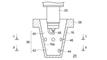
- FIG. 2 is a cross-sectional view schematically showing the partition wall and spark plug shown in FIG. 1.
- FIG. 2B is a sectional view taken along line BB of the partition wall shown in FIG. 2A.
- 2A is a cross-sectional view taken along the line CC of the partition wall shown in FIG. 2A.
- FIG. FIG. 7 is a cross-sectional view showing an example of a partition wall and a spark plug of an engine according to a third embodiment.
- FIG. 7 is a cross-sectional view schematically showing a partition wall and a spark plug of an engine according to a sixth embodiment.
- FIG. 7 is a schematic diagram schematically showing a partition wall and an injection nozzle of an engine according to a seventh embodiment.
- an engine 1A includes a piston 10, a cylinder block 12, a cylinder head 14, a partition wall 16, an injection nozzle 18, and a spark plug 20.
- the cylinder block 12 is provided with a cylinder 22 in which the piston 10 reciprocates.
- the cylinder head 14 is fixed to the cylinder block 12 and forms a main chamber (combustion chamber) 24 between it and the piston 10.
- the cylinder head 14 is provided with an intake port 26 and an exhaust port 28.
- two intake ports 26 and two exhaust ports 28 are provided for one main chamber 24, but the invention is not limited to this.
- the intake port 26 is provided with an intake valve 30 that opens and closes the intake port 26, and the exhaust port 28 is provided with an exhaust valve 32 that opens and closes the exhaust port 28.
- the intake port 26 is provided with an injection nozzle 34 (hereinafter referred to as "port injector 34") that injects fuel, but the port injector 34 is not essential.
- the partition wall 16 is provided on the main chamber side of the cylinder head 14, and forms an auxiliary chamber (preliminary combustion chamber) 36 within the main chamber.
- the injection nozzle 18 (hereinafter referred to as "direct injector 18") is an injection nozzle that injects fuel into the main chamber.
- the spark plug 20 is installed in the subchamber and is capable of igniting the air-fuel mixture that has flowed into the subchamber.
- the port injector 34 injects fuel during the intake stroke in which the intake valve 30 opens the intake port 26 and the piston 10 descends. As a result, the air-fuel mixture is supplied from the intake port 26 to the main chamber 24 .
- the air-fuel mixture in the main chamber is a lean air-fuel mixture that is thinner than the stoichiometric air-fuel ratio.
- the direct injector 18 injects fuel. Thereby, the fuel injected from the direct injector 18 is supplied to the auxiliary chamber 36 together with the air-fuel mixture in the main chamber.
- the air-fuel mixture in the pre-chamber is near the stoichiometric air-fuel ratio.
- the air-fuel mixture in the pre-chamber is ignited by the spark plug 20.
- the air-fuel mixture in the auxiliary chamber becomes a flame and is injected into the main chamber, thereby combusting the air-fuel mixture in the main chamber.
- the engine 1A is operated by repeating these intake stroke, compression stroke, expansion stroke, and exhaust stroke.
- the partition wall 16 has a truncated conical outer shape.
- a flange 38 is provided at the end of the large diameter side of the partition wall 16, and the partition wall 16 is fixed to the main chamber side of the cylinder head 14 by this flange 38.
- the large diameter side of the partition wall 16 becomes the proximal end side fixed to the cylinder head 14, and the small diameter side becomes the distal end side located on the piston side.
- the partition wall 16 has a truncated conical subchamber 36 therein.
- the large diameter side of the subchamber 36 forms a subchamber base 40 located on the cylinder head side, and the small diameter side forms a subchamber tip 42 located on the piston side.
- the partition wall 16 has a swirl flow generation communication passage 44 and a flame injection communication passage 46.
- the swirl flow generation communication passage 44 is a communication passage leading from the main chamber 24 to the auxiliary chamber 36, and is inclined with respect to the direction toward the center O of the auxiliary chamber 36 in the circumferential direction of the cylinder 22, as shown in FIG. 2B. (for example, provided at an angle ⁇ ).
- the flame injection communication passage 46 is a communication passage that communicates from the auxiliary chamber 36 to the main chamber 24, and is located at a different position from the swirl flow generation communication passage 44 in the circumferential direction or the extending direction of the cylinder 22, as shown in FIG. 2C. It is provided.
- the flame injection communication passage 46 is provided straight toward the center of the auxiliary chamber 36 in the circumferential direction of the cylinder 22 .
- the partition wall 16 includes a suppressing means for suppressing flame injection from the swirl flow generation communication passage 44.
- the suppressing means may be of any type as long as it suppresses the flame injected from the swirl flow generation communication path 44 to be smaller than the flame injected from the flame injection communication path 46.
- the air-fuel mixture is supplied from the main chamber 24 to the auxiliary chamber 36 through the swirl flow generation communication passage 44 and the flame injection communication passage 46 during the compression stroke of the engine 1A.
- the air-fuel mixture supplied from the swirl flow generation communication passage 44 swirls along the sub-chamber side wall surface 16a of the partition wall 16 to generate a swirl flow SF in the sub-chamber.
- the spark plug 20 ignites the air-fuel mixture in the pre-chamber. Then, the air-fuel mixture in the auxiliary chamber becomes a flame and is injected into the main chamber through the flame injection communication passage 46 and the swirl flow generation communication passage 44. At this time, the flame injection from the main chamber 24 through the swirl flow generation communication passage 44 is suppressed by the suppressing means. As a result, the energy of the flame emitted from the flame injection communication passage 46 increases, and a decrease in the energy of the flame injection from the flame injection communication passage 46 can be suppressed. The flame injected into the main chamber through the flame injection communication passage 46 and the swirl flow generation communication passage 44 combusts the air-fuel mixture within the main chamber.
- the suppressing means suppresses the flame injection from the swirl flow generation communication passage 44, the flame injection energy from the flame injection communication passage 46 increases, and the flame injection communication passage 46 increases. It is possible to suppress a decrease in the flame injection energy from the flame. Thereby, it is possible to generate a swirl flow SF in the subchamber and to suppress a decrease in flame injection energy.
- the suppressing means is that the maximum flow passage cross-sectional area A1 of the swirl flow generation communication passage 44 is made smaller than the minimum flow passage cross-sectional area A2 of the flame injection communication passage 46.
- the diameters (diameters) of the swirl flow generation communication passage 44 and the flame injection communication passage 46 are constant, the diameter (diameter) D1 of the swirl flow generation communication passage 44 is smaller than the diameter D2 of the flame injection communication passage 46. do.
- the other configuration of the engine 1B according to the second embodiment is the same as the configuration of the engine 1A according to the first embodiment described above.
- the maximum flow passage cross-sectional area A1 of the swirl flow generation communication passage 44 is made smaller than the minimum flow passage cross-section area A2 of the flame injection communication passage 46, so that during the expansion stroke of the engine 1B, the main chamber 24 through the swirl flow generation communication path 44 is suppressed.
- Other operations of the engine 1B according to the second embodiment are the same as those of the engine 1A according to the first embodiment described above.
- the suppressing means is to make the distance from the swirl flow generation communication passage 44 to the spark plug 20 longer than the distance from the flame injection communication passage 46 to the spark plug 20.
- the flame injection communication passage 46 is provided on the base end side of the partition wall 16, while the flame injection communication passage 46 is provided on the distal end side of the partition wall 16.
- the flame injection communication passage 46 is provided at the front end side of the partition wall 16; By providing the swirl flow generation communication passage 44 on the side, the distance from the swirl flow generation communication passage 44 to the spark plug 20 is made longer than the distance from the flame injection communication passage 46 to the spark plug 20.
- the other configuration of the engine 1C according to the third embodiment is the same as the configuration of the engine 1A or 1B according to the first or second embodiment described above.
- the suppressing means is an obstacle provided between the spark plug 20 and the swirl flow generation communication path 44.
- the obstacle is, for example, an eave-like structure, and is arranged so as to suppress the injection of flame from the swirl flow generation communication passage 44 during the expansion stroke of the engine 1D.
- the other configuration of the engine 1D according to the fourth embodiment is the same as the configuration of any one of the engines 1A to 1C according to the first to third embodiments described above.
- the suppressing means is that the swirl flow generation communication passage 44 is made longer than the flame injection communication passage 46.
- the swirl flow generation communication passage 44 is made longer than the flame injection communication passage 46.
- the other configuration of the engine 1E according to the fifth embodiment is the same as the configuration of any one of the engines 1A to 1D according to the first to fourth embodiments described above.
- the ignition point 48 of the spark plug 20 and the flame injection communication passage 46 are provided in the pre-chamber base 40, the swirl flow generation communication passage 44 is provided in the pre-chamber tip 42, and the suppressing means is , the volume of the sub-chamber tip 42 is made smaller than the volume of the sub-chamber base 40.
- a truncated conical sub-chamber base 40 in which the tip of the spark plug 20 is accommodated is provided on the base end side of the partition wall 16, and a sub-chamber base 40 is provided on the distal end side of the partition wall 16.
- a step surface 50 is provided at the boundary between the sub-chamber base 40 and the sub-chamber tip 42, and the volume of the sub-chamber tip 42 is made smaller than the volume of the sub-chamber base 40. It's smaller than that.
- the other configuration of the engine 1F according to the sixth embodiment is the same as the configuration of any one of the engines 1A to 1E according to the first to fifth embodiments described above.
- the flame separates at the boundary between the sub-chamber base 40 and the sub-chamber tip 42. This makes it difficult for the flame to flow from the sub-chamber base 40 to the sub-chamber tip 42, and suppresses flame injection from the swirl flow generation communication passage 44 provided in the sub-chamber tip 42. As a result, the energy of the flame ejected from the flame injection communication passage 46 provided in the sub-chamber base 40 increases, so that a decrease in the energy of the flame injection from the flame injection communication passage 46 can be suppressed.
- the suppressing means has a curved surface on the upstream side in the swirl flow direction of the sub-chamber side opening of the flame injection communication passage 46, and a corner portion on the upstream side of the swirl flow generation communication passage 44. It is to be.
- the upstream side in the swirl flow direction of the opening on the side of the sub-chamber of the flame injection communication passage 46 is rounded (so-called R-chamfering), while the opening on the side of the sub-chamber of the swirl flow generation communication passage 44 is left as is.
- the other configuration of the engine 1G according to the seventh embodiment is the same as the configuration of any one of the engines 1A to 1F according to the first to sixth embodiments described above.
- the upstream side in the swirl flow direction of the sub-chamber side opening of the flame injection communication passage 46 is a curved surface, and the upstream side of the swirl flow generation communication passage 44 is a corner.
- the flow rate coefficient of the combustion gas injected from the flame injection communication passage 46 becomes larger than the flow rate coefficient of the combustion gas injected from the swirl flow generation communication passage 44, and the injection energy of the flame flow from the flame injection communication passage 46 increases. do. Thereby, a decrease in the injection energy of the flame stream from the flame injection communication passage 46 can be suppressed.
- the swirl flow generation communication passage 44 extends from the subchamber 36 toward the main chamber 24 in the circumferential direction of the cylinder 22 on the side where the direct injector 18 is provided. It is installed facing the opposite side. Furthermore, the swirl flow generation communication passage 44 is provided on the opposite side of the direct injector 18 in the circumferential direction of the cylinder 22 . Note that the swirl flow generation communication passage 44 may be provided at least in the circumferential direction of the cylinder 22 from the auxiliary chamber 36 toward the main chamber 24 on the side opposite to the side where the injection nozzle 18 is provided. It may be provided on the direct injector 18 side.
- the other configuration of the engine 1H according to the seventh embodiment is the same as the configuration of any one of the engines 1A to 1G according to the first to sixth embodiments described above.
- the swirl flow generation communication passage 44 extends from the auxiliary chamber 36 toward the main chamber 24 in the circumferential direction of the cylinder 22, toward the side opposite to the side where the direct injector 18 is provided. Since it is provided in the subchamber 36, it is possible to suppress the generation of a flow of air-fuel mixture containing a large amount of fuel on the partition wall side of the subchamber 36, and to stratify the inside of the subchamber 36. Furthermore, by providing the swirl flow generation communication passage 44 on the opposite side of the direct injector 18 in the circumferential direction of the cylinder 22, the air-fuel mixture containing more fuel can be moved closer to the partition wall side of the auxiliary chamber 36. generation can be suppressed.
Landscapes
- Engineering & Computer Science (AREA)
- Chemical & Material Sciences (AREA)
- Combustion & Propulsion (AREA)
- Mechanical Engineering (AREA)
- General Engineering & Computer Science (AREA)
- Combustion Methods Of Internal-Combustion Engines (AREA)
Priority Applications (2)
| Application Number | Priority Date | Filing Date | Title |
|---|---|---|---|
| JP2024509693A JP7740516B2 (ja) | 2022-03-25 | 2022-03-25 | エンジン |
| PCT/JP2022/014592 WO2023181393A1 (ja) | 2022-03-25 | 2022-03-25 | エンジン |
Applications Claiming Priority (1)
| Application Number | Priority Date | Filing Date | Title |
|---|---|---|---|
| PCT/JP2022/014592 WO2023181393A1 (ja) | 2022-03-25 | 2022-03-25 | エンジン |
Publications (1)
| Publication Number | Publication Date |
|---|---|
| WO2023181393A1 true WO2023181393A1 (ja) | 2023-09-28 |
Family
ID=88100312
Family Applications (1)
| Application Number | Title | Priority Date | Filing Date |
|---|---|---|---|
| PCT/JP2022/014592 Ceased WO2023181393A1 (ja) | 2022-03-25 | 2022-03-25 | エンジン |
Country Status (2)
| Country | Link |
|---|---|
| JP (1) | JP7740516B2 (https=) |
| WO (1) | WO2023181393A1 (https=) |
Citations (3)
| Publication number | Priority date | Publication date | Assignee | Title |
|---|---|---|---|---|
| JPS52170903U (https=) * | 1976-06-21 | 1977-12-26 | ||
| WO2020196207A1 (ja) * | 2019-03-27 | 2020-10-01 | 三菱自動車工業株式会社 | 副室式内燃機関 |
| WO2021161553A1 (ja) * | 2020-02-10 | 2021-08-19 | 三菱自動車工業株式会社 | 副室式火花点火エンジン |
-
2022
- 2022-03-25 WO PCT/JP2022/014592 patent/WO2023181393A1/ja not_active Ceased
- 2022-03-25 JP JP2024509693A patent/JP7740516B2/ja active Active
Patent Citations (3)
| Publication number | Priority date | Publication date | Assignee | Title |
|---|---|---|---|---|
| JPS52170903U (https=) * | 1976-06-21 | 1977-12-26 | ||
| WO2020196207A1 (ja) * | 2019-03-27 | 2020-10-01 | 三菱自動車工業株式会社 | 副室式内燃機関 |
| WO2021161553A1 (ja) * | 2020-02-10 | 2021-08-19 | 三菱自動車工業株式会社 | 副室式火花点火エンジン |
Also Published As
| Publication number | Publication date |
|---|---|
| JP7740516B2 (ja) | 2025-09-17 |
| JPWO2023181393A1 (https=) | 2023-09-28 |
Similar Documents
| Publication | Publication Date | Title |
|---|---|---|
| US10208653B2 (en) | Pre-chamber of an internal combustion engine | |
| US7926463B2 (en) | Cylinder injection type spark ignition internal combustion engine | |
| JP2018096218A (ja) | 副室式ガスエンジン | |
| WO2021161553A1 (ja) | 副室式火花点火エンジン | |
| JPS5936089B2 (ja) | 副燃焼室付内燃機関 | |
| JPH03115722A (ja) | 副室式アルコールエンジン | |
| EP2998538A1 (en) | Pre-chamber of internal combustion engine | |
| GB2106179A (en) | Spark ignition pre-combustion chamber internal combustion engine | |
| WO2023181393A1 (ja) | エンジン | |
| JP2009215973A (ja) | 副室式内燃機関 | |
| WO2004099584A1 (ja) | 副室式ガス機関の燃焼室構造及び副室式ガス機関 | |
| US4058090A (en) | Internal combuston engine with auxiliary combustion chamber | |
| JP7571759B2 (ja) | エンジン | |
| JP7768352B2 (ja) | エンジン | |
| JP7652120B2 (ja) | エンジン | |
| JP2023023760A (ja) | 内燃機関用のスパークプラグ及びこれを備えた内燃機関 | |
| JP7578069B2 (ja) | 内燃機関用のスパークプラグ | |
| JP7524796B2 (ja) | 内燃機関 | |
| WO2021161552A1 (ja) | 副室式エンジン | |
| JP7487595B2 (ja) | 内燃機関用のスパークプラグ及び内燃機関 | |
| JP2526324Y2 (ja) | トーチ点火式ガスエンジンのトーチ点火装置 | |
| JPWO2023181398A5 (https=) | ||
| JP3082403B2 (ja) | エンジンの吸気装置 | |
| JP2009270542A (ja) | エンジン及びエンジン用点火プラグ | |
| JP2023016618A (ja) | 内燃機関用のスパークプラグ及びこれを備えた内燃機関 |
Legal Events
| Date | Code | Title | Description |
|---|---|---|---|
| 121 | Ep: the epo has been informed by wipo that ep was designated in this application |
Ref document number: 22933531 Country of ref document: EP Kind code of ref document: A1 |
|
| ENP | Entry into the national phase |
Ref document number: 2024509693 Country of ref document: JP Kind code of ref document: A |
|
| NENP | Non-entry into the national phase |
Ref country code: DE |
|
| 122 | Ep: pct application non-entry in european phase |
Ref document number: 22933531 Country of ref document: EP Kind code of ref document: A1 |