WO2023181338A1 - 無線システム - Google Patents
無線システム Download PDFInfo
- Publication number
- WO2023181338A1 WO2023181338A1 PCT/JP2022/014296 JP2022014296W WO2023181338A1 WO 2023181338 A1 WO2023181338 A1 WO 2023181338A1 JP 2022014296 W JP2022014296 W JP 2022014296W WO 2023181338 A1 WO2023181338 A1 WO 2023181338A1
- Authority
- WO
- WIPO (PCT)
- Prior art keywords
- wireless
- remote
- base
- wireless system
- power supply
- Prior art date
- Legal status (The legal status is an assumption and is not a legal conclusion. Google has not performed a legal analysis and makes no representation as to the accuracy of the status listed.)
- Ceased
Links
Images



Classifications
-
- H—ELECTRICITY
- H02—GENERATION; CONVERSION OR DISTRIBUTION OF ELECTRIC POWER
- H02J—ELECTRIC POWER NETWORKS; CIRCUIT ARRANGEMENTS OR SYSTEMS FOR SUPPLYING OR DISTRIBUTING ELECTRIC POWER; SYSTEMS FOR STORING ELECTRIC ENERGY
- H02J50/00—Circuit arrangements or systems for wireless supply or distribution of electric power
- H02J50/10—Circuit arrangements or systems for wireless supply or distribution of electric power using inductive coupling
-
- H—ELECTRICITY
- H02—GENERATION; CONVERSION OR DISTRIBUTION OF ELECTRIC POWER
- H02J—ELECTRIC POWER NETWORKS; CIRCUIT ARRANGEMENTS OR SYSTEMS FOR SUPPLYING OR DISTRIBUTING ELECTRIC POWER; SYSTEMS FOR STORING ELECTRIC ENERGY
- H02J50/00—Circuit arrangements or systems for wireless supply or distribution of electric power
- H02J50/40—Circuit arrangements or systems for wireless supply or distribution of electric power using two or more transmitting or receiving devices
-
- G—PHYSICS
- G05—CONTROLLING; REGULATING
- G05B—CONTROL OR REGULATING SYSTEMS IN GENERAL; FUNCTIONAL ELEMENTS OF SUCH SYSTEMS; MONITORING OR TESTING ARRANGEMENTS FOR SUCH SYSTEMS OR ELEMENTS
- G05B19/00—Program-control systems
- G05B19/02—Program-control systems electric
- G05B19/04—Program control other than numerical control, i.e. in sequence controllers or logic controllers
- G05B19/042—Program control other than numerical control, i.e. in sequence controllers or logic controllers using digital processors
-
- G—PHYSICS
- G05—CONTROLLING; REGULATING
- G05B—CONTROL OR REGULATING SYSTEMS IN GENERAL; FUNCTIONAL ELEMENTS OF SUCH SYSTEMS; MONITORING OR TESTING ARRANGEMENTS FOR SUCH SYSTEMS OR ELEMENTS
- G05B2219/00—Program-control systems
- G05B2219/30—Nc systems
- G05B2219/33—Director till display
- G05B2219/33192—Radio link, wireless
-
- H—ELECTRICITY
- H02—GENERATION; CONVERSION OR DISTRIBUTION OF ELECTRIC POWER
- H02J—ELECTRIC POWER NETWORKS; CIRCUIT ARRANGEMENTS OR SYSTEMS FOR SUPPLYING OR DISTRIBUTING ELECTRIC POWER; SYSTEMS FOR STORING ELECTRIC ENERGY
- H02J50/00—Circuit arrangements or systems for wireless supply or distribution of electric power
- H02J50/20—Circuit arrangements or systems for wireless supply or distribution of electric power using microwaves or radio frequency waves
-
- H—ELECTRICITY
- H02—GENERATION; CONVERSION OR DISTRIBUTION OF ELECTRIC POWER
- H02J—ELECTRIC POWER NETWORKS; CIRCUIT ARRANGEMENTS OR SYSTEMS FOR SUPPLYING OR DISTRIBUTING ELECTRIC POWER; SYSTEMS FOR STORING ELECTRIC ENERGY
- H02J50/00—Circuit arrangements or systems for wireless supply or distribution of electric power
- H02J50/80—Circuit arrangements or systems for wireless supply or distribution of electric power involving the exchange of data, concerning supply or distribution of electric power, between transmitting devices and receiving devices
Definitions
- the present invention relates to a wireless system.
- Japanese Patent No. 5497730 discloses an FA system in which a PC and a controller are connected via a field network. In Japanese Patent No. 5497730, wireless messages are sent and received.
- the present invention aims to solve the above-mentioned problems.
- a wireless system includes a base wireless device, a remote wireless device that wirelessly communicates with the base wireless device, a sensor device that wirelessly transmits a signal to the remote wireless device, and at least a wireless communication device that wirelessly transmits a signal to the remote wireless device.
- a wireless power supply device that supplies power.
- a wireless system includes a computer, a first base wireless device connected to the computer via a field bus, a first remote wireless device that wirelessly communicates with the first base wireless device, and a first remote wireless device that performs wireless communication with the first base wireless device.
- a first sensor device that transmits a signal to one remote wireless device; a second base wireless device connected to the computer by the fieldbus; and a second sensor device that wirelessly transmits a signal to the second base wireless device.
- a wireless power supply device that wirelessly supplies power to at least the first sensor device, and another wireless power supply device that wirelessly supplies power to the second sensor device.
- a good wireless system can be provided.
- FIG. 1 is a diagram showing the configuration of a wireless system according to the first embodiment.
- FIG. 2 is a block diagram showing a wireless system according to the first embodiment.
- FIG. 3 is a diagram showing an example of production equipment.
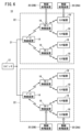
- FIG. 4 is a diagram showing the configuration of a wireless system according to the second embodiment.
- FIG. 5 is a block diagram showing a wireless system according to the second embodiment.
- FIG. 6 is a diagram showing the configuration of a wireless system according to the third embodiment.
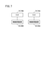
- FIG. 7 is a diagram showing part of a wireless system according to the third embodiment.
- FIG. 8 is a diagram showing part of a wireless system according to the fourth embodiment.
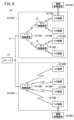
- FIG. 9 is a diagram showing the configuration of a wireless system according to the fifth embodiment.
- FIG. 1 is a diagram showing the configuration of a wireless system according to this embodiment.
- FIG. 2 is a block diagram showing a wireless system according to this embodiment.
- FIG. 3 is a diagram showing an example of production equipment.
- the wireless system 10 may include a computer 12, a base wireless device 14, a remote wireless device 16, a sensor device 18, and a wireless power supply device 20.
- Wireless system 10 may include multiple base wireless devices 14.
- One computer 12 and multiple base wireless devices 14 may be connected via fieldbus 21.
- Two base radio devices 14 of the plurality of base radio devices 14 are shown in FIG.
- Pairing may be performed in advance between the base wireless device 14 and the remote wireless device 16.
- a synchronous connection may be made between the paired base wireless device 14 and remote wireless device 16.
- a plurality of remote wireless devices 16 can be synchronously connected to one base wireless device 14 .
- the base wireless device 14 can wirelessly transmit and receive signals to and from a plurality of remote wireless devices 16 .
- Pairing may be performed in advance between the remote wireless device 16 and the sensor device 18.
- a synchronous connection may be made between the paired remote wireless device 16 and sensor device 18.
- a plurality of sensor devices 18 may be synchronously connected to one remote wireless device 16 .
- the remote wireless device 16 can wirelessly transmit and receive signals to and from the plurality of sensor devices 18 .
- the network 22 can be configured by synchronously connecting the base wireless device 14 and the remote wireless device 16 and synchronously connecting the remote wireless device 16 and the sensor device 18.
- a plurality of networks 22 may be configured in the wireless system 10. Two networks 22 of the plurality of networks 22 are shown in FIG.
- the computer 12 can monitor and control the production equipment (industrial equipment) 70 (see FIG. 3).
- a PLC Programmable Logic Controller
- the computer 12 may include, for example, a calculation section 24 and a storage section 26.
- the calculation unit 24 may include, for example, a processor such as a CPU (Central Processing Unit). That is, the calculation unit 24 may include a processing circuit.
- the calculation unit 24 may include a control unit 30. Although the calculation unit 24 may include components other than the control unit 30, the components other than the control unit 30 are omitted here for the sake of simplification of explanation.
- the control unit 30 is in charge of overall control of the computer 12.
- the control unit 30 can monitor and control the production equipment 70.
- the control unit 30 can be realized by the calculation unit 24 executing a program stored in the storage unit 26 . Note that at least a portion of the control unit 30 may be realized by an integrated circuit such as an ASIC (Application Specific Integrated Circuit) or an FPGA (Field-Programmable Gate Array). At least a portion of the control unit 30 may be an electronic circuit including a discrete device.
- ASIC Application Specific Integrated Circuit
- FPGA Field-Programmable Gate Array
- the storage unit 26 may include a volatile memory (not shown) and a nonvolatile memory (not shown). Examples of the volatile memory include RAM (Random Access Memory). Volatile memory is used as a working memory of a processor and temporarily stores data and the like required for processing or calculations. Examples of the nonvolatile memory include ROM (Read Only Memory), flash memory, and the like. Non-volatile memory is used as storage memory and stores programs, tables, maps, etc. At least a portion of the storage unit 26 may be included in a processor, an integrated circuit, or the like as described above. The storage unit 26 may further include an HDD (Hard Disk Drive), an SSD (Solid State Drive), and the like.
- HDD Hard Disk Drive
- SSD Solid State Drive
- the computer 12 may further include an input/output interface 28 for realizing a fieldbus connection.
- Computer 12 may communicate with base wireless device 14 via fieldbus 21 .
- the base wireless device 14 may include, for example, a calculation section 32 and a storage section 34.
- the calculation unit 32 may include, for example, a processor such as a CPU. That is, the calculation unit 32 may include a processing circuit.
- the calculation unit 32 may include a control unit 36 and a transmission/reception processing unit 38. Although the calculation unit 32 may include components other than these components, the components other than these components are omitted here for the sake of simplification of explanation.
- the control unit 36 and the transmission/reception processing unit 38 can be realized by the calculation unit 32 executing a program stored in the storage unit 34 .
- the control unit 36 is in charge of overall control of the base wireless device 14. Note that at least part of the control unit 36 and the transmission/reception processing unit 38 may be realized by an integrated circuit such as an ASIC or an FPGA. At least a portion of the control unit 36 and the transmission/reception processing unit 38 may be an electronic circuit including a discrete device.
- the storage unit 34 may include a volatile memory (not shown) and a nonvolatile memory (not shown). Examples of volatile memory include RAM and the like. Volatile memory is used as a working memory of a processor and temporarily stores data and the like required for processing or calculations. Examples of nonvolatile memory include ROM, flash memory, and the like. Non-volatile memory is used as storage memory and stores programs, tables, maps, etc. At least a portion of the storage unit 34 may be included in a processor, an integrated circuit, or the like as described above.
- the base wireless device 14 may further include an input/output interface 40 for realizing fieldbus connection.
- Base radio device 14 may be connected to computer 12 by fieldbus 21, as described above.
- the base wireless device 14 may further include a communication unit 42 for performing wireless communication.
- the base wireless device 14 can perform wireless communication with the remote wireless device 16 using the communication unit 42 .
- the remote wireless device 16 may include, for example, a calculation unit 44 and a storage unit 46.
- the calculation unit 44 may include, for example, a processor such as a CPU. That is, the calculation unit 44 may include a processing circuit.
- the calculation unit 44 may include a control unit 48 and a transmission/reception processing unit 50. Although the calculation unit 44 may include components other than these components, the components other than these components will be omitted here to simplify the explanation.
- the control unit 48 and the transmission/reception processing unit 50 can be realized by the calculation unit 44 executing a program stored in the storage unit 46.
- the control unit 48 is in charge of overall control of the remote wireless device 16. Note that at least part of the control unit 48 and the transmission/reception processing unit 50 may be realized by an integrated circuit such as an ASIC or an FPGA. At least a portion of the control unit 48 and the transmission/reception processing unit 50 may be an electronic circuit including a discrete device.
- the storage unit 46 may include a volatile memory (not shown) and a nonvolatile memory (not shown). Examples of volatile memory include RAM and the like. Volatile memory is used as a working memory of a processor and temporarily stores data and the like required for processing or calculations. Examples of nonvolatile memory include ROM, flash memory, and the like. Non-volatile memory is used as storage memory and stores programs, tables, maps, etc. At least a portion of the storage unit 46 may be included in a processor, an integrated circuit, or the like as described above.
- the remote wireless device 16 may further include communication units 52A and 52B for performing wireless communication.
- the remote wireless device 16 can perform wireless communication with the base wireless device 14 using the communication unit 52A. Further, the remote wireless device 16 can perform wireless communication with the sensor device 18 using the communication unit 52B.
- the wireless communication performed between the base wireless device 14 and the remote wireless device 16 and the wireless communication performed between the remote wireless device 16 and the sensor device 18 do not need to be synchronized.
- the wireless communication protocol performed between the base wireless device 14 and the remote wireless device 16 and the wireless communication protocol performed between the remote wireless device 16 and the sensor device 18 may be the same, or May be different.
- the difference between the wireless communication protocol performed between the base wireless device 14 and the remote wireless device 16 and the wireless communication protocol performed between the remote wireless device 16 and the sensor device 18 is that the data This can contribute to reducing the amount.
- the frequency band used in wireless communication performed between the base wireless device 14 and remote wireless device 16 and the frequency band used in wireless communication performed between remote wireless device 16 and sensor device 18 are as follows: They may be the same or different. It is possible to make the frequency band used in the wireless communication performed between the base wireless device 14 and the remote wireless device 16 different from the frequency band used in the wireless communication performed between the remote wireless device 16 and the sensor device 18. , it can contribute to reducing the amount of data in wireless communication.
- the sensor device 18 may include, for example, a calculation section 56, a storage section 58, and a sensor element 60.
- the calculation unit 56 may include, for example, a processor such as a CPU. That is, the calculation unit 56 may include a processing circuit.
- the calculation unit 56 may include a control unit 62 and a transmission/reception processing unit 64. Although the calculation unit 56 may include components other than these components, the components other than these components will be omitted here to simplify the explanation.
- the control unit 62 and the transmission/reception processing unit 64 can be realized by the calculation unit 56 executing a program stored in the storage unit 58.
- the control unit 62 controls the entire sensor device 18 . Note that at least a portion of the control unit 62 and the transmission/reception processing unit 64 may be realized by an integrated circuit such as an ASIC or an FPGA. At least a portion of the control unit 62 and the transmission/reception processing unit 64 may be an electronic circuit including a discrete device.
- the storage unit 58 may include a volatile memory (not shown) and a nonvolatile memory (not shown). Examples of volatile memory include RAM and the like. Volatile memory is used as a working memory of a processor and temporarily stores data and the like required for processing or calculations. Examples of nonvolatile memory include ROM, flash memory, and the like. Non-volatile memory is used as storage memory and stores programs, tables, maps, etc. At least a portion of the storage unit 58 may be included in a processor, an integrated circuit, or the like as described above.
- the sensor element 60 is, for example, a magnetic sensor, but is not limited thereto.
- FIG. 3 is a diagram showing an example of production equipment.
- the production equipment 70 may be equipped with an actuator 72.
- the sensor device 18 may be included in the actuator 72, for example, but is not limited thereto.
- the actuator 72 may include, for example, a cylinder device, but is not limited thereto.
- the sensor device 18 can output a signal according to the stroke position of the actuator 72, for example, but is not limited thereto.
- the actuator 72 may be equipped with one sensor device 18 or a plurality of sensor devices 18.
- the sensor device 18 may further include a communication section 66 for performing wireless communication.
- the sensor device 18 can perform wireless communication with the remote wireless device 16 using the communication unit 66 .
- the sensor device 18 may further include a wireless power receiving section 68.
- the wireless power receiving unit 68 can receive power wirelessly supplied from the wireless power supply device 20.
- the wireless power receiving unit 68 receives power supplied from the wireless power supply device 20 via an antenna (not shown).
- the wireless power receiving unit 68 may include a rectifier circuit (not shown) or the like. The rectifier circuit or the like rectifies the AC power received from the wireless power supply device 20 to generate DC power.
- the wireless power receiving unit 68 can supply DC power to each component of the sensor device 18.
- the wireless power supply device 20 can perform wireless power supply.
- the wireless power supply device 20 can wirelessly supply power to the plurality of sensor devices 18, but is not limited thereto.
- the wireless power supply device 20 can perform wireless power supply via the antenna 74 (see FIG. 7).
- the wireless power supply device 20 can perform wireless power supply using electromagnetic waves.
- electromagnetic waves for example, microwaves can be used.
- the frequency band of microwaves used for wireless power supply is, for example, a 920 MHz band, but is not limited thereto.
- microwaves in the 2.4 GHz frequency band may be used for the wireless power supply.
- microwaves in a frequency band of 5.7 GHz may be used for the wireless power supply.
- wireless communication can be performed between the sensor device 18 and the remote wireless device 16.
- the frequency band used in the wireless communication performed between the sensor device 18 and the remote wireless device 16 is, for example, the Industry-Science-Medical frequency band (ISM band).
- wireless communication can be performed between the remote wireless device 16 and the base wireless device 14.
- the frequency band used in the wireless communication performed between the remote wireless device 16 and the base wireless device 14 is, for example, an industrial, scientific, and medical frequency band.
- Power can be supplied to the computer 12, the base wireless device 14, and the remote wireless device 16 by wire.
- the wireless system 10 according to this embodiment is configured.
- power can be supplied to the sensor device 18 by the wireless power supply device 20.
- the sensor device 18 and the remote wireless device 16 may communicate wirelessly. Therefore, according to this embodiment, wiring for supplying power to the sensor device 18 is not required. Therefore, according to this embodiment, such disconnection of the wiring cannot occur. Moreover, since such wiring is not required, according to this embodiment, the degree of freedom in arranging the sensor device 18 and the like can be improved. In this way, according to this embodiment, a good wireless system 10 can be provided.
- FIG. 4 is a diagram showing the configuration of a wireless system according to this embodiment.
- FIG. 5 is a block diagram showing a wireless system according to this embodiment. Components that are the same as those of the wireless system according to the first embodiment shown in FIGS. 1 to 3 are given the same reference numerals to omit or simplify the explanation.
- the sensor device 18 can be wirelessly powered, but also the remote wireless device 16 can be wirelessly powered.
- the remote wireless device 16 may be equipped with a wireless power receiving section 54.
- the wireless power receiving unit 54 can receive power wirelessly supplied from the wireless power supply device 20.
- the wireless power receiving unit 54 can receive power wirelessly supplied from the wireless power supply device 20.
- the wireless power receiving unit 54 receives power supplied from the wireless power supply device 20 via an antenna (not shown).
- the wireless power receiving unit 54 may include a rectifier circuit (not shown) or the like. The rectifier circuit or the like rectifies the AC power received from the wireless power supply device 20 to generate DC power.
- the wireless power receiving unit 54 can supply DC power to each component of the remote wireless device 16.
- the wireless power supply device 20 can wirelessly supply power to both the remote wireless device 16 and the sensor device 18.
- Power can be supplied to the computer 12 and the base wireless device 14 by wire.
- the wireless system 10 according to this embodiment is configured.
- wireless power supply can be performed not only to the sensor device 18 but also to the remote wireless device 16.
- wireless power supply can also be performed to the remote wireless device 16, so that no wiring is required to supply power to the remote wireless device 16. Therefore, according to the present embodiment, disconnection of the wiring for supplying power to the remote wireless device 16 cannot occur.
- the degree of freedom in arranging the remote wireless device 16 can also be improved. In this way, according to this embodiment, a better wireless system 10 can be provided.
- FIG. 6 is a diagram showing the configuration of a wireless system according to this embodiment. Components that are the same as those of the wireless system according to the first or second embodiment shown in FIGS. 1 to 5 are given the same reference numerals to omit or simplify the explanation.
- wireless power supply to the remote wireless device 16 may be performed by a wireless power supply device 20B that is separate from the wireless power supply device 20A that performs wireless power supply to the sensor device 18.
- the wireless system 10 may include a wireless power supply device 20A and a wireless power supply device 20B.
- the wireless power supply device 20A can wirelessly supply power to the sensor device 18.
- the wireless power supply device 20B can wirelessly supply power to the remote wireless device 16.
- reference numeral 20 is used, and when describing individual wireless power supply devices separately, reference numerals 20A and 20B are used.
- FIG. 7 is a diagram showing part of the wireless system according to this embodiment. An example of an antenna connection is shown in FIG.
- the wireless power supply device 20A may be equipped with an antenna 74A.
- the wireless power feeding device 20B may be equipped with an antenna 74B.
- the antennas 74A and 74B are for wireless power feeding. When describing individual antennas without distinguishing them, reference numeral 74 is used, and when describing individual antennas while distinguishing them, reference numerals 74A and 74B are used. As shown in FIG. 7, separate antennas 74A and 74B may be provided in each of the wireless power supply devices 20A and 20B.
- wireless power supply to the remote wireless device 16 may be performed by a wireless power supply device 20B that is separate from the wireless power supply device 20A that wirelessly supplies power to the sensor device 18.
- FIG. 8 is a diagram showing part of the wireless system according to this embodiment. An example of an antenna connection is shown in FIG. Components that are the same as those of the wireless systems according to the first to third embodiments shown in FIGS. 1 to 7 are given the same reference numerals to omit or simplify the explanation.
- a plurality of antennas 74 are connected to the wireless power supply device 20.
- the wireless power supply device 20 can perform wireless power supply via the plurality of antennas 74.
- one of the plurality of antennas 74 is used to wirelessly feed power to the sensor device 18, and the other of the plurality of antennas 74 is used to wirelessly feed power to the remote wireless device 16, but the present invention is not limited thereto.
- three or more antennas 74 may be connected to the wireless power supply device 20.
- a plurality of antennas 74 may be connected to the wireless power supply device 20.
- FIG. 9 is a diagram showing the configuration of a wireless system according to this embodiment. Components that are the same as those of the wireless systems according to the first to fourth embodiments shown in FIGS. 1 to 8 are given the same reference numerals to omit or simplify the explanation.
- wireless power supply can be performed between the base wireless device 14B and the sensor device 18B without going through the remote wireless device 16.
- wireless communication can be performed between the base wireless device 14A and the remote wireless device 16 in the network 22A. Further, in the network 22A, wireless communication can be performed between the remote wireless device 16 and the sensor device 18A.
- the reference numeral 14 is used, and when the individual base devices are explained separately, the reference numerals 14A and 14B are used.
- the reference numeral 18 is used, and when the individual sensor devices are explained separately, the reference numerals 18A and 18B are used.
- wireless power supply can be performed between the base wireless device 14B and the sensor device 18B without going through the remote wireless device 16.
- the wireless power supply device 20C can wirelessly supply power to the sensor device 18 that constitutes the network 22A.
- the wireless power supply device 20C may not only wirelessly supply power to the sensor device 18A that constitutes the network 22A, but also wirelessly supply power to the remote wireless device 16 that constitutes the network 22A.
- wireless power supply to the remote wireless device 16 that constitutes the network 22A may be performed by a wireless power supply device (not shown) that is separate from the wireless power supply device 20C.
- the wireless power supply device 20D can wirelessly supply power to the sensor device 18B that constitutes the network 22B.
- wireless communication can be performed between the base wireless device 14B and the sensor device 18B without going through the remote wireless device 16 in the network 22B.
- wireless communication can be performed between the base wireless device 14B and the sensor device 18B without going through the remote wireless device 16, so the remote wireless device 16 is not required in the network 22B. Therefore, according to this embodiment, it is possible to reduce the cost of the wireless system 10.
- the wireless system (10) includes a base wireless device (14), a remote wireless device (16) that wirelessly communicates with the base wireless device, and a sensor device (18) that wirelessly transmits a signal to the remote wireless device.
- a wireless power supply device (20) that wirelessly supplies power to at least the sensor device is provided. According to such a configuration, wiring for supplying power to the sensor device is not required. Therefore, with such a configuration, such disconnection of the wiring cannot occur. Moreover, since such wiring is not required, such a configuration can improve the degree of freedom in arranging the sensor device and the like. According to such a configuration, a good wireless system can be provided.
- the remote wireless device may be wirelessly supplied with power by the wireless power supply device.
- wireless power supply can also be performed to the remote wireless device, so there is no need for wiring for powering the remote wireless device. Therefore, according to such a configuration, disconnection of the wiring for supplying power to the remote wireless device cannot occur.
- the degree of freedom in arranging the remote wireless device can also be improved. According to such a configuration, a better wireless system can be provided.
- the above wireless system may further include another wireless power supply device (20B) that wirelessly supplies power to the remote wireless device.
- another wireless power supply device (20B) that wirelessly supplies power to the remote wireless device.
- the frequency of electromagnetic waves used in the wireless power feeding performed by the wireless power feeding device may be the same as the frequency of the electromagnetic waves used in the wireless power feeding performed by the other wireless power feeding device.
- the frequency of the electromagnetic waves used in the wireless power feeding performed by the wireless power feeding device and the frequency of the electromagnetic waves used in the wireless power feeding performed by the other wireless power feeding device may be different.
- the wireless power feeding device may perform the wireless power feeding using a plurality of antennas (74).
- a plurality of the base radio devices are provided, further comprising a computer (12) connected to the plurality of base radio devices via a field bus (21), and one of the plurality of base radio devices is at least one base wireless device (14B) wirelessly receives a transmitted signal from another sensor device (18B) without going through a remote wireless device, said other sensor device receiving another wireless power supply.
- Wireless power may be supplied from the device (20D). According to such a configuration, a signal transmitted from another sensor device can be wirelessly received by the base wireless device without going through a remote wireless device, which can contribute to cost reduction.
- the sensor device may detect the state of the actuator (72). Since there is no need for wiring between the sensor device that detects the state of the actuator and the remote wireless device, the risk of failure due to disconnection can be significantly reduced.
- the actuator may be provided in production equipment (70). Such a configuration can contribute to improving productivity.
- a plurality of the sensor devices may be provided for one actuator.
- one of the remote wireless devices may wirelessly receive a signal transmitted from each of the plurality of sensor devices.
- one base wireless device may perform wireless communication with a plurality of remote wireless devices.
- a wireless communication protocol performed between the base wireless device and the remote wireless device and a wireless communication protocol performed between the remote wireless device and the sensor device are different. Good too.
- a frequency band used in wireless communication performed between the base wireless device and the remote wireless device and a frequency band used in wireless communication performed between the remote wireless device and the sensor device.
- the band may be different.
- the wireless system (10) includes a computer (12), a first base wireless device (14A) connected to the computer via a field bus (21), and a first remote wireless device that wirelessly communicates with the first base wireless device.
- a first sensor device (18A) for transmitting a signal to the first remote wireless device a second base wireless device (14B) connected to the computer by the fieldbus; and a second base wireless device (14B) connected to the computer by the fieldbus.
- a second sensor device (18B) that wirelessly transmits a signal to a wireless device, a wireless power supply device (20C) that wirelessly supplies power to at least the first sensor device, and another wireless power supply that wirelessly supplies power to the second sensor device.
- a power supply device (20D) is provided. According to such a configuration, the signal transmitted from the second sensor device can be wirelessly received by the second base wireless device without going through the remote wireless device, which can contribute to cost reduction of the wireless system. .
- Wireless system 12 Computer 14, 14A, 14B: Base wireless device 16: Remote wireless device 18, 18A, 18B: Sensor device 20, 20A to 20D: Wireless power supply device 21: Field bus 22, 22A, 22B: Network 24 , 32, 44, 56: Arithmetic unit 26, 34, 46, 58: Storage unit 28, 40: Input/output interface 30, 36, 48, 62: Control unit 38, 50, 64: Transmission/reception processing unit 42, 52A, 52B , 66: Communication section 54, 68: Wireless power receiving section 60: Sensor element 70: Production equipment 72: Actuator 74, 74A, 74B: Antenna
Landscapes
- Engineering & Computer Science (AREA)
- Computer Networks & Wireless Communication (AREA)
- Power Engineering (AREA)
- Physics & Mathematics (AREA)
- General Physics & Mathematics (AREA)
- Automation & Control Theory (AREA)
- Arrangements For Transmission Of Measured Signals (AREA)
- Mobile Radio Communication Systems (AREA)
- Selective Calling Equipment (AREA)
Priority Applications (10)
| Application Number | Priority Date | Filing Date | Title |
|---|---|---|---|
| PCT/JP2022/014296 WO2023181338A1 (ja) | 2022-03-25 | 2022-03-25 | 無線システム |
| CN202512023160.9A CN121663832A (zh) | 2022-03-25 | 2022-03-25 | 无线系统 |
| EP26151977.1A EP4707967A3 (en) | 2022-03-25 | 2022-03-25 | Wireless system |
| EP22933478.4A EP4503385A4 (en) | 2022-03-25 | 2022-03-25 | WIRELESS SYSTEM |
| US18/849,252 US20250202280A1 (en) | 2022-03-25 | 2022-03-25 | Wireless system |
| JP2024509643A JP7813346B2 (ja) | 2022-03-25 | 2022-03-25 | 無線システム |
| CN202280093942.1A CN118947039A (zh) | 2022-03-25 | 2022-03-25 | 无线系统 |
| KR1020247035798A KR20240170552A (ko) | 2022-03-25 | 2022-03-25 | 무선 시스템 |
| TW112110016A TW202345488A (zh) | 2022-03-25 | 2023-03-17 | 無線系統 |
| JP2025249589A JP2026031813A (ja) | 2022-03-25 | 2025-12-15 | 無線システム |
Applications Claiming Priority (1)
| Application Number | Priority Date | Filing Date | Title |
|---|---|---|---|
| PCT/JP2022/014296 WO2023181338A1 (ja) | 2022-03-25 | 2022-03-25 | 無線システム |
Publications (1)
| Publication Number | Publication Date |
|---|---|
| WO2023181338A1 true WO2023181338A1 (ja) | 2023-09-28 |
Family
ID=88100259
Family Applications (1)
| Application Number | Title | Priority Date | Filing Date |
|---|---|---|---|
| PCT/JP2022/014296 Ceased WO2023181338A1 (ja) | 2022-03-25 | 2022-03-25 | 無線システム |
Country Status (7)
| Country | Link |
|---|---|
| US (1) | US20250202280A1 (https=) |
| EP (2) | EP4503385A4 (https=) |
| JP (2) | JP7813346B2 (https=) |
| KR (1) | KR20240170552A (https=) |
| CN (2) | CN118947039A (https=) |
| TW (1) | TW202345488A (https=) |
| WO (1) | WO2023181338A1 (https=) |
Citations (6)
| Publication number | Priority date | Publication date | Assignee | Title |
|---|---|---|---|---|
| JP2007514558A (ja) * | 2003-12-17 | 2007-06-07 | アーベーベー・リサーチ・リミテッド | 産業用ロボットのためのツール |
| JP5497730B2 (ja) | 2009-02-23 | 2014-05-21 | 三菱電機株式会社 | 無線通信システム、無線通信装置および無線通信方法 |
| JP2015177581A (ja) * | 2014-03-13 | 2015-10-05 | パナソニックIpマネジメント株式会社 | 非接触給電装置 |
| JP2018050186A (ja) * | 2016-09-21 | 2018-03-29 | 株式会社東芝 | 通信装置およびコンピュータプログラム |
| JP2018510594A (ja) * | 2015-01-27 | 2018-04-12 | ロシックス・インコーポレイテッド | 非対称ネットワークアーキテクチャを有するワイヤレスセンサネットワークを提供するシステム及び方法 |
| JP2018081681A (ja) * | 2016-11-15 | 2018-05-24 | パロ アルト リサーチ センター インコーポレイテッド | 無線建物センサシステム |
Family Cites Families (1)
| Publication number | Priority date | Publication date | Assignee | Title |
|---|---|---|---|---|
| US20070021140A1 (en) * | 2005-07-22 | 2007-01-25 | Keyes Marion A Iv | Wireless power transmission systems and methods |
-
2022
- 2022-03-25 EP EP22933478.4A patent/EP4503385A4/en active Pending
- 2022-03-25 CN CN202280093942.1A patent/CN118947039A/zh active Pending
- 2022-03-25 KR KR1020247035798A patent/KR20240170552A/ko active Pending
- 2022-03-25 EP EP26151977.1A patent/EP4707967A3/en active Pending
- 2022-03-25 WO PCT/JP2022/014296 patent/WO2023181338A1/ja not_active Ceased
- 2022-03-25 US US18/849,252 patent/US20250202280A1/en active Pending
- 2022-03-25 JP JP2024509643A patent/JP7813346B2/ja active Active
- 2022-03-25 CN CN202512023160.9A patent/CN121663832A/zh active Pending
-
2023
- 2023-03-17 TW TW112110016A patent/TW202345488A/zh unknown
-
2025
- 2025-12-15 JP JP2025249589A patent/JP2026031813A/ja active Pending
Patent Citations (6)
| Publication number | Priority date | Publication date | Assignee | Title |
|---|---|---|---|---|
| JP2007514558A (ja) * | 2003-12-17 | 2007-06-07 | アーベーベー・リサーチ・リミテッド | 産業用ロボットのためのツール |
| JP5497730B2 (ja) | 2009-02-23 | 2014-05-21 | 三菱電機株式会社 | 無線通信システム、無線通信装置および無線通信方法 |
| JP2015177581A (ja) * | 2014-03-13 | 2015-10-05 | パナソニックIpマネジメント株式会社 | 非接触給電装置 |
| JP2018510594A (ja) * | 2015-01-27 | 2018-04-12 | ロシックス・インコーポレイテッド | 非対称ネットワークアーキテクチャを有するワイヤレスセンサネットワークを提供するシステム及び方法 |
| JP2018050186A (ja) * | 2016-09-21 | 2018-03-29 | 株式会社東芝 | 通信装置およびコンピュータプログラム |
| JP2018081681A (ja) * | 2016-11-15 | 2018-05-24 | パロ アルト リサーチ センター インコーポレイテッド | 無線建物センサシステム |
Non-Patent Citations (1)
| Title |
|---|
| See also references of EP4503385A4 |
Also Published As
| Publication number | Publication date |
|---|---|
| EP4707967A3 (en) | 2026-05-06 |
| CN121663832A (zh) | 2026-03-13 |
| JPWO2023181338A1 (https=) | 2023-09-28 |
| CN118947039A (zh) | 2024-11-12 |
| EP4503385A4 (en) | 2025-11-26 |
| TW202345488A (zh) | 2023-11-16 |
| JP7813346B2 (ja) | 2026-02-12 |
| KR20240170552A (ko) | 2024-12-03 |
| US20250202280A1 (en) | 2025-06-19 |
| EP4707967A2 (en) | 2026-03-11 |
| JP2026031813A (ja) | 2026-02-24 |
| EP4503385A1 (en) | 2025-02-05 |
Similar Documents
| Publication | Publication Date | Title |
|---|---|---|
| KR101618856B1 (ko) | 다수의 IoT 디바이스를 연계시키는 IoT 게이트웨이 장치 | |
| CN101584155B (zh) | 具有主/从结构的通信系统 | |
| US7656846B2 (en) | PLC based wireless communications | |
| CN103414020B (zh) | 一种天线阵列控制装置、方法以及系统 | |
| US11723086B2 (en) | Human machine interface for mission critical wireless communication link nodes | |
| CN115915405A (zh) | 针对键合丝设备集群的控制方法及装置 | |
| US20130285462A1 (en) | Apparatus and method for transmitting wireless energy in energy transmission system | |
| WO2023181338A1 (ja) | 無線システム | |
| US9543789B2 (en) | Apparatus and method for transmitting/receiving wireless energy in energy transmission system | |
| KR101797032B1 (ko) | IoT 게이트웨이 기능을 가지는 무선 라우터 장치 | |
| CN106326174A (zh) | 一种两线通信电路 | |
| CN111148082B (zh) | 一种伺服驱动器的通讯装置、伺服驱动器及机器人 | |
| KR20200140030A (ko) | 복수의 안테나 모듈들을 제어하는 방법 및 그 전자 장치 | |
| JP2023078294A (ja) | 無線アンテナモジュール及び無線システム | |
| EP3198751B1 (en) | Dynamic configuration of body coupled communication devices | |
| CN107948947A (zh) | 用于车辆到x通信的通信设备 | |
| CN112600782A (zh) | 无线充电系统及其通讯方法、可存储介质 | |
| US20240160591A1 (en) | I/o unit, master unit, and communications system | |
| WO2020002555A1 (en) | Power management in a system on chip | |
| US20210351949A1 (en) | Communication system and connector | |
| JP3223652U (ja) | デュアルモード通信装置 | |
| JP2019204718A (ja) | 照明器具 | |
| CN121548973A (zh) | 一种输入/输出交换设备 | |
| CN103888175B (zh) | 用于无线通信系统的快速连接方法 | |
| CN118764065A (zh) | 一种电调天线接口以及基站 |
Legal Events
| Date | Code | Title | Description |
|---|---|---|---|
| 121 | Ep: the epo has been informed by wipo that ep was designated in this application |
Ref document number: 22933478 Country of ref document: EP Kind code of ref document: A1 |
|
| ENP | Entry into the national phase |
Ref document number: 2024509643 Country of ref document: JP Kind code of ref document: A |
|
| WWE | Wipo information: entry into national phase |
Ref document number: 18849252 Country of ref document: US Ref document number: 202280093942.1 Country of ref document: CN |
|
| ENP | Entry into the national phase |
Ref document number: 20247035798 Country of ref document: KR Kind code of ref document: A |
|
| WWE | Wipo information: entry into national phase |
Ref document number: 1020247035798 Country of ref document: KR Ref document number: 2022933478 Country of ref document: EP |
|
| NENP | Non-entry into the national phase |
Ref country code: DE |
|
| ENP | Entry into the national phase |
Ref document number: 2022933478 Country of ref document: EP Effective date: 20241025 |
|
| WWP | Wipo information: published in national office |
Ref document number: 18849252 Country of ref document: US |