WO2023181248A1 - Vehicle frame structure - Google Patents
Vehicle frame structure Download PDFInfo
- Publication number
- WO2023181248A1 WO2023181248A1 PCT/JP2022/013906 JP2022013906W WO2023181248A1 WO 2023181248 A1 WO2023181248 A1 WO 2023181248A1 JP 2022013906 W JP2022013906 W JP 2022013906W WO 2023181248 A1 WO2023181248 A1 WO 2023181248A1
- Authority
- WO
- WIPO (PCT)
- Prior art keywords
- vehicle
- width direction
- vehicle width
- cross
- inner member
- Prior art date
Links
- 230000002787 reinforcement Effects 0.000 claims description 20
- 238000003466 welding Methods 0.000 description 11
- 230000003014 reinforcing effect Effects 0.000 description 10
- 230000035939 shock Effects 0.000 description 4
- 238000003780 insertion Methods 0.000 description 3
- 230000037431 insertion Effects 0.000 description 3
- 230000002093 peripheral effect Effects 0.000 description 3
- 239000000725 suspension Substances 0.000 description 3
- 238000010521 absorption reaction Methods 0.000 description 2
- 238000012856 packing Methods 0.000 description 2
- 229910000831 Steel Inorganic materials 0.000 description 1
- 238000005452 bending Methods 0.000 description 1
- 230000007423 decrease Effects 0.000 description 1
- 230000000694 effects Effects 0.000 description 1
- 239000002184 metal Substances 0.000 description 1
- 239000010959 steel Substances 0.000 description 1
Images


Classifications
-
- B—PERFORMING OPERATIONS; TRANSPORTING
- B62—LAND VEHICLES FOR TRAVELLING OTHERWISE THAN ON RAILS
- B62D—MOTOR VEHICLES; TRAILERS
- B62D21/00—Understructures, i.e. chassis frame on which a vehicle body may be mounted
- B62D21/02—Understructures, i.e. chassis frame on which a vehicle body may be mounted comprising longitudinally or transversely arranged frame members
Definitions
- the present invention relates to a vehicle frame structure.
- Vehicles such as pickup trucks are equipped with, for example, a pair of side members spaced apart from each other in the vehicle width direction as strength members. Further, the pair of side members are connected by a plurality of cross members extending substantially in the vehicle width direction to form a chassis frame.
- leaf springs as suspension devices.
- the front and rear ends of the leaf spring are swingably supported by the side members, respectively.
- a rear end portion of a leaf spring is supported by a side member via a shackle.
- the side members are often made of, for example, a steel plate and have a rectangular box-like or U-shaped vertical cross section. Furthermore, in order to reduce the weight of vehicles, there is a demand for reducing the thickness of the subframe as much as possible.
- the present invention has been made to solve these problems, and aims to reduce the weight of a vehicle having a chassis frame formed by connecting a pair of left and right side members with a cross member while ensuring the rigidity of the side members.
- the purpose is to provide a frame structure for a vehicle that can
- the frame structure of a vehicle of the present invention includes a pair of side members arranged at intervals in the vehicle width direction and extending in the longitudinal direction of the vehicle, and a pair of side members extending in the vehicle width direction.
- the joint portion between the first member and the second member is located forward of a center position of the width of the cross member in the longitudinal direction of the vehicle.
- the inner member can be divided into the first member and the second member to shorten the length of the parts, thereby improving the yield of the parts and reducing the cost of the parts.
- the cross member is connected to cover the joint between the first member and the second member, the strength of the side member at the joint between the first and second members can be ensured.
- this joint can be firmly fixed. By doing so, the rigidity of the entire frame including the side members and cross members can be efficiently improved and deformation can be suppressed.
- the cross member is disposed at the rearmost of a plurality of cross members provided in the vehicle that connect the pair of side members, and the first member is arranged at least at the rearmost part of the cross members of the second member. It is preferable that the thickness is thinner than the portion adjacent to the first member. As a result, by reducing the thickness of the first member that extends rearward from the rearmost cross member, the weight of the side member is reduced, and the first member collapses in the event of a rear-end collision of the vehicle, making it easier to absorb the collision load. Can be done.
- the first member is thinner than a portion of the outer member adjacent to the outer side of the first member in the vehicle width direction, and a portion of the first member is thinner than a portion of the outer member adjacent to the outer side of the first member in the vehicle width direction.
- the outer member is formed wider in the vehicle width direction than the outer member adjacent to the outside.
- the first member is configured such that the width in the vehicle width direction increases toward the rear of the vehicle.
- the weight of the rear part of the side member can be further reduced, and the rear part of the side member can be more easily crushed in the event of a rear collision, thereby further improving shock absorption.
- the width in the vehicle width direction of the rear end portion of the first member is the same as the width in the vehicle width direction of the rear end portion of the side member.
- the side member further includes a reinforcement extending in the vehicle width direction and connecting inner walls on both sides in the vehicle width direction, and the reinforcement is provided at a connection portion between the side member and the cross member. It is recommended that the vehicle be placed at the front and rear positions of the vehicle. Thereby, the rigidity and strength of the connection portion between the side member and the cross member can be improved by reinforcement.
- the part length of the inner member is shortened to reduce parts cost, and the cross member ensures the rigidity of the side member at the joint between the first member and the second member. be able to.
- the joint between the first member and the second member is located in front of the center position of the longitudinal width of the cross member, the first A connecting portion between the member and the second member is arranged.
- this connecting portion By firmly fixing this connecting portion, the rigidity of the entire frame including the side members and cross member can be efficiently improved and deformation can be suppressed.
- FIG. 1 is a perspective view schematically showing the structure of a lower rear portion of a vehicle according to an embodiment of the present invention.
- FIG. 1 is a perspective view showing a schematic structure of a chassis frame of a vehicle according to the present embodiment. It is a perspective view showing the structure of the attachment part of the cargo box in the rear part of the side member concerning this embodiment.
- FIG. 3 is a perspective view showing a structure near a connecting portion between a left side member and a rearmost cross member according to the present embodiment.
- FIG. 3 is a top view showing the structure near the connection portion between the left side member and the rearmost cross member according to the present embodiment.
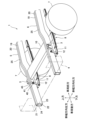
- FIG. 1 is a perspective view showing a schematic structure of a lower rear portion of a vehicle 1 according to an embodiment of the present invention.
- FIG. 2 is a perspective view showing a schematic structure of the chassis frame 2 of the vehicle 1 according to the present embodiment.
- FIG. 3 is a perspective view showing the structure of the mounting portion of the cargo box 4 at the rear of the side member according to the present embodiment.
- a vehicle 1 according to an embodiment employing the frame structure of the present invention is a vehicle equipped with a cargo box 4 and a suspension device 8 using leaf springs 11, such as a pickup truck, for example.
- the vehicle 1 includes a pair of side members 5 and 6 that extend in the longitudinal direction of the vehicle and are spaced apart from each other in the vehicle width direction. Further, the pair of side members 5 and 6 are connected by a plurality of cross members to form the chassis frame 2. The cross members extend in the vehicle width direction and are arranged at intervals in the vehicle longitudinal direction.
- a cargo box 4 is placed on the chassis frame 2. The cargo box 4 is fixed to a mount bracket 3 fixed to the side members 5 and 6 with bolts and nuts (not shown).
- a plurality of mount brackets 3 are provided on the outside of the side members 5 and 6 in the vehicle width direction and spaced apart from each other in the vehicle longitudinal direction.
- the mount bracket 3 disposed at the rearmost position of the vehicle is provided near the rearmost cross member 10 at the longitudinal position of the vehicle.
- the axle of the rear wheel 7 of the vehicle 1 is suspended by a suspension device 8 using a leaf spring 11.
- the leaf springs 11 are arranged below the side members 5 and 6 so as to extend in the direction in which the side members 5 and 6 extend, that is, in the longitudinal direction of the vehicle.
- the front end portion of the leaf spring 11 is rotatably supported in the vehicle vertical direction by the side members 5 and 6 via a front connecting shaft (not shown).
- the rear end portion of the leaf spring 11 is rotatably supported by the side members 5 and 6 via a shackle 12 in the vertical direction of the vehicle.
- the shackle 12 is supported by the side members 5 and 6 behind and near the cross member 10.
- the shackle 12 is connected to the side members 5, 6 by a shackle pin 41 inserted into an insertion hole 13 extending in the vehicle width direction provided in the side wall of the side members 5, 6, and supported rotatably around the insertion hole 13. At the same time, the rear end portion of the leaf spring 11 is supported rotatably about an axis extending in the vehicle width direction.
- the side members 5 and 6 are formed by abutting and welding both ends of an inner member 19 and an outer member 20, which are formed by bending a sheet metal member into a U-shape.
- the side members 5 and 6 are hollow and have a box-shaped longitudinal section, and have an upper wall 21, a lower wall 22, an inner wall 23, and an outer wall 24.
- the upper wall 21 and the lower wall 22 have a weld line 25 which is a butt portion between the inner member 19 and the outer member 20.
- the cross member 10 has a hollow shape with a box-shaped cross section, and has an upper wall 26, a lower wall 27, a front wall 28, and a rear wall 29.
- the end of the cross member 10 is abutted against an inner wall 23 of the side member on the inner side in the vehicle width direction and is fixed by welding.
- the mount bracket 3 has a U-shaped upper and lower cross section, and has an upper wall 30 and two supporting side walls 31 and 32.
- the mount bracket 3 is arranged such that the upper wall 30 and supporting side walls 31 and 32 extend perpendicularly from the outer walls 24 of the side members 5 and 6 in the vehicle width direction.
- the upper wall 30 of the mount bracket 3 has approximately the same vertical height as the upper wall 21 of the side members 5 and 6, and is arranged to extend in the horizontal direction of the vehicle 1. They are arranged so that they are spaced apart from each other in the direction. Therefore, the opening of the mount bracket 3, which has a U-shaped cross section, is arranged so as to face downward.
- outer flange portions 35 ends of the supporting side walls 31 and 32 of the mount bracket 3 on the side members 5 and 6 are bent vertically outward in the longitudinal direction of the vehicle to provide outer flange portions 35, respectively.
- the outer flange portion 35 faces the outer wall 24 of the side member, and its outer peripheral portion is fixed to the outer wall 24 by welding.
- the outer flange portion 35 of the mount bracket 3 has an outer end portion cut out in a substantially semicircular shape to form a cutout portion 36 .
- a bolt hole 37 is provided in the upper wall 30 of the mount bracket 3, and a bolt hole 37 is provided in a strength member at the bottom of the packing box 4, or a bolt hole provided in a mount bracket fixed to the bottom of the packing box 4.
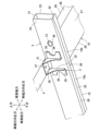
- FIG. 4 and 5 show the structure near the connection between the side member 5 and the cross member 10 according to the embodiment of the present invention, with FIG. 4 being a perspective view and FIG. 5 being a top view. Note that FIG. 4 is a view of the connecting portion between the side member 5 on the left side in the vehicle width direction and the rearmost cross member 10, viewed from approximately the center in the vehicle width direction and from the rear.
- the side member 5 is provided with a cylindrical portion 40 that connects the shackle 12 near the rear of the cross member 10.
- the cylindrical part 40 is a cylindrical member, arranged so that its axis extends in the vehicle width direction and passes through the side member 5, and has an insertion hole 13 formed therein into which a circular rod-shaped shackle pin 41 is inserted.
- the shackle 12 has a pair of plate members whose one end portions are arranged to sandwich the side member 5 from side to side, and the one end portion of the shackle 12 is rotatably supported by the side member 5 in the front-rear direction by a shackle pin 41. be done.
- Both ends of the cylindrical portion 40 are respectively arranged so as to slightly protrude outward from the side walls (inner wall 23, outer wall 24) of the side member 5, and are fixed to the side wall of the side member 5 by, for example, welding. There is.
- the inner end of the cylindrical portion 40 is provided with a reinforcing portion 45 that protrudes radially outward from the outer peripheral wall of the cylindrical portion 40 .
- the reinforcing part 45 is a plate-like member having a hole into which the inner end of the cylindrical part 40 is inserted, and is fixed all around by welding to the outer peripheral surface of the inner end of the cylindrical part 40 . Further, the reinforcing portion 45 faces the inner wall 23 of the side member 5 and is fixed by welding. Therefore, one end portion of the cylindrical portion 40 is fixed to the side member 5 via the reinforcing portion 45.
- the reinforcing portion 45 extends linearly toward the front of the vehicle along the inner surface of the side member 5 to a position close to the rear wall 29 of the cross member 10. Further, the supporting side wall 31 of the vehicle rearmost mount bracket 3 on the vehicle rear side is arranged at a vehicle longitudinal position between the rear wall 29 of the vehicle rearmost cross member 10 and the front end of the reinforcing portion 45. Note that the reinforcing portion 45 may extend toward the front of the vehicle until it comes into contact with the rear wall 29 of the cross member 10.
- the rear wall 29 of the cross member 10, the front end of the reinforcing portion 45, and the support side wall 31 on the rear side of the vehicle of the mount bracket 3 at the rear of the vehicle may be arranged so that the longitudinal positions of the vehicle substantially coincide with each other or in the vicinity. .
- the inner member 19 on the inside in the vehicle width direction of the side member 5 is located between the front wall 28 and the rear wall 29 of the cross member 10 and in a position forward of the center position in the longitudinal direction of the cross member 10, on the front side of the vehicle. It is divided into an inner member 19a (second member) and a rear inner member 19b (first member) on the rear side of the vehicle. The rear end of the front inner member 19a and the front end of the rear inner member 19b are joined by welding (joint portion 38). Furthermore, the rear inner member 19b is formed thinner than the front inner member 19a and the outer member 20.
- the rear inner member 19b is located at a position rearward from the cylindrical portion 40, and its length in the vehicle width direction gradually increases linearly as it extends toward the rear of the vehicle.
- the length in the vehicle width direction gradually decreases as it extends rearward.
- the proportion occupied by the rear inner member 19b becomes larger than that of the outer member 20 as the side member 5 moves toward the rear of the vehicle from the cylindrical portion 40.
- the outer member 20 has only an outer wall 24 without substantially having an upper wall 21 or a lower wall 22, and the width of the rear inner member 19b in the vehicle width direction is equal to the width of the side member 5 in the vehicle width direction. are almost the same.
- the reinforcements 50 and 51 are rectangular thick plate members, and the entire circumference is welded and fixed to the inner wall of the side member 5. That is, the reinforcements 50 and 51 have the effect of supporting the inner wall of the side member 5 and improving the strength and rigidity of the side member 5.
- the reinforcement 50 on the rear side of the vehicle is arranged at a longitudinal position of the vehicle between the rear wall 29 of the rearmost cross member 10 of the vehicle and the front end of the reinforcing portion 45.
- the reinforcement 50 on the rear side of the vehicle is arranged at substantially the same position or in the vicinity of the rear wall 29 of the cross member 10, the front end of the reinforcing portion 45, and the support side wall 31 of the mount bracket 3 on the rear side of the vehicle. It's okay.
- the reinforcement 51 on the front side of the vehicle is located slightly behind the front wall 28 of the cross member 10 and slightly forward of the joint 38 between the front inner member 19a and the rear inner member 19b.
- the reinforcement 50 has a two-part structure including an inner reinforcement 50a fixed to the inner member 19 and an outer reinforcement 50b fixed to the outer member 20.
- the inner reinforcement 51a is fixed to the inside of the inner member 19 by welding
- the outer reinforcement 51b is fixed to the inside of the outer member 20 by welding.
- the structure of the left side member 5 of the vehicle has been described, but the right side member 6 of the vehicle may also have a symmetrical and similar structure.
- the side members 5 and 6 are constituted by an inner member 19 on the inside in the vehicle width direction and an outer member 20 on the outside in the vehicle width direction. Furthermore, the inner member 19 is formed by welding together parts that are divided in the longitudinal direction of the vehicle, such as a front inner member 19a on the front side of the vehicle and a rear inner member 19b on the rear side of the vehicle. Thereby, the component length of the inner member 19 can be shortened, so that the yield of components can be improved and component costs can be reduced.
- the front inner member 19a and the rear inner member 19b are joined at a vehicle longitudinal position between the front wall 28 and the rear wall 29 of the cross member 10. Since the cross member 10 is connected to cover the joint 38 between the front inner member 19a and the rear inner member 19b, the strength and rigidity of the side members 5 and 6 can be ensured.
- the inner member 19 is constructed by joining a rear inner member 19b on the rear side of the vehicle and a front inner member 19a on the front side of the vehicle, which is longer than the rear inner member 19b. Therefore, for example, due to the input from the rear tire that is loaded during off-road driving, the front periphery of the connecting portion between the side members 5, 6 and the cross member 10 has a structure that tends to undergo torsional deformation relative to the rear periphery. It becomes. According to this configuration, the width in the vehicle longitudinal direction of the cross member 10 is located at the front of the connection between the side members 5 and 6 and the cross member 10, where deformation is likely to occur, that is, near the rear tire, and where the contribution to torsional rigidity is high.
- the rigidity of the entire chassis frame 2 including the side members 5, 6 and the cross member 10 can be increased by arranging the joint portion where the front inner member 19a and the rear inner member 19b are stacked in front of the center position. It is possible to improve efficiency and suppress deformation.
- the cross member 10 at the longitudinal position where the front inner member 19a and the rear inner member 19b are joined is disposed at the rearmost of the plurality of cross members of the vehicle 1, the cross member 10 at the rearmost position
- the thickness of the rear inner member 19b, which extends further to the rear, is thinner than that of the front inner member 19a. This makes it possible to reduce the weight of the inner member 19, and by extension the side members 5 and 6, and to make it easier to absorb the collision load by crushing the rear inner member 19b in the event of a rear collision of the vehicle.
- the outer member 20 is thicker than the rear inner member 19b, the outer member 20 can ensure the required rigidity and strength while reducing the weight by using the thinner rear inner member 19b.
- the width in the vehicle width direction of the rear inner member 19b is approximately the same as the width in the vehicle width direction of the outer member 20 at the connection position with the cross member 10, and the width in the vehicle width direction increases toward the rear end behind the cylindrical portion 40. It has become. Therefore, behind the cylindrical portion 40, the width in the vehicle width direction of the thin rear inner member 19b is equal to or larger than the width in the vehicle width direction of the outer member 20, and the side members 5 and 6 can be easily crushed. This makes it possible to improve shock absorption in the event of a rear collision.
- the width of the rear inner member 19b in the vehicle width direction is approximately the same as the width of the side members 5, 6 in the vehicle width direction. can be further reduced in weight.
- the width of the front inner member 19a in the vehicle width direction increases linearly rather than stepwise toward the rear ends of the side members 5 and 6, stress concentration in the side members 5 and 6 can be suppressed. can. Therefore, the rear end portions of the side members 5 and 6 are more likely to be crushed uniformly in the event of a rear collision, and the shock absorbability can be further improved.
- two reinforcements 50 and 51 are provided in the side members 5 and 6 near the connection part of the cross member 10 at an interval in the longitudinal direction of the vehicle, so that the reinforcements 50 and 51 near the connection part with the cross member 10 are
- the strength and rigidity of the side members 5 and 6 can be improved. Therefore, even if stress occurs in the connection portion of the side members 5, 6, deformation of the cross section of the side members 5, 6 can be suppressed. Thereby, the torsional rigidity of the side members 5 and 6 can be improved, and the maneuverability of the vehicle can be improved.
- the reinforcement 51 on the front side of the vehicle is arranged near the joint part 38 between the front inner member 19a and the rear inner member 19b. Therefore, the strength and rigidity of the side members 5 and 6 near the joint 38 between the front inner member 19a and the rear inner member 19b can be improved.
- the outer flange portion 35 of the mount bracket 3 has a substantially semicircular cutout at its outer end to form a cutout portion 36, so that the outer flange portion 35 and the outer wall 24 of the side member are fixed. It is possible to secure a long welding length for this purpose. Furthermore, by extending the upper part of the outer flange portion 35 on the rear side of the vehicle closer to the cylindrical portion 40, the distance between the support portion of the leaf spring 11 and the mount bracket 3 is shortened, and the rigidity near the cylindrical portion 40 is reduced. can be improved.
- the present invention is not limited to the embodiments described above.
- the rear inner member 19b is thinner than the front inner member 19a and the outer member 20, but it may be made thinner in only a portion.
- the joint portion 38 between the front inner member 19a and the rear inner member 19b is arranged at the connection portion between the cross member 10 and the side members 5 and 6 at the rearmost portion of the vehicle.
- the joint between the front inner member 19a and the rear inner member 19b may be arranged at the joint between the front inner member 19a and the rear inner member 19b.
- the detailed structures of the side members 5, 6, cross member 10, etc. may be changed as appropriate.
- the present invention can also be widely applied to vehicles having a chassis frame configured by connecting a pair of side members with a cross member.
Abstract
A vehicle frame structure configured by connecting a pair of left and right side members by means of a cross member 10, wherein the side members 5 have an inner member 19 on the inside in the vehicle width direction and an outer member 20 on the outside in the vehicle width direction, the inner member 19 is configured by joining a rear inner member 19b at the rear of the vehicle and a front inner member 19a at the front of the vehicle, the rear inner member 19b is formed of a thin plate-like member that is thinner than the front inner member 19a, and the joined portion of the front inner member 19a and the rear inner member 19b is set forward of a center position in the front-to-rear width of the cross member 10, at the connecting portion of the side members 5 and the cross member 10.
Description
本発明は、車両のフレーム構造に関する。
The present invention relates to a vehicle frame structure.
ピックアップトラック等の車両には、強度部材として、例えば車幅方向に互いに間隔をおいて一対のサイドメンバを備えている。更に、この一対のサイドメンバは、略車幅方向に延びる複数のクロスメンバによって接続されてシャシフレームが構成されている。
Vehicles such as pickup trucks are equipped with, for example, a pair of side members spaced apart from each other in the vehicle width direction as strength members. Further, the pair of side members are connected by a plurality of cross members extending substantially in the vehicle width direction to form a chassis frame.
また、ピックアップトラックのように積載荷重の比較的大きい車両の多くには、サスペンション装置としてリーフスプリングが使用されている。リーフスプリングは、前後端部がサイドメンバに夫々揺動可能に支持されている。例えば特許文献1では、リーフスプリングの後端部がシャックルを介してサイドメンバに支持されている。
Additionally, many vehicles with relatively large payloads, such as pickup trucks, use leaf springs as suspension devices. The front and rear ends of the leaf spring are swingably supported by the side members, respectively. For example, in Patent Document 1, a rear end portion of a leaf spring is supported by a side member via a shackle.
サイドメンバは、強度及び剛性を確保するとともに軽量化を図るため、例えば鋼板によって縦断面が矩形箱状やコの字状に形成されている場合が多い。更に、車両の軽量化を図るために、サブフレームの板厚を少しでも薄くしたいといった要求がある。
In order to ensure strength and rigidity as well as reduce weight, the side members are often made of, for example, a steel plate and have a rectangular box-like or U-shaped vertical cross section. Furthermore, in order to reduce the weight of vehicles, there is a demand for reducing the thickness of the subframe as much as possible.
しかしながら、サイドメンバにおいてシャックルとの連結部や、マウントブラケットが配置された部位には、リーフスプリングや荷箱から大きな荷重が入力するため、特に剛性及び強度を十分に確保する必要がある。
However, in the side member, a large load is input from the leaf spring and the cargo box to the connection part with the shackle and the part where the mount bracket is arranged, so it is particularly necessary to ensure sufficient rigidity and strength.
本発明はこのような問題を解決するためになされたもので、左右一対のサイドメンバをクロスメンバで接続して形成したシャシフレームを有する車両において、サイドメンバの剛性を確保しつつ軽量化を図ることができる車両のフレーム構造を提供することを目的とする。
The present invention has been made to solve these problems, and aims to reduce the weight of a vehicle having a chassis frame formed by connecting a pair of left and right side members with a cross member while ensuring the rigidity of the side members. The purpose is to provide a frame structure for a vehicle that can
上記目的を達成するため、本発明の車両のフレーム構造は、車両の車幅方向に間隔をおいて配置され、前記車両の前後方向に延在する一対のサイドメンバと、前記車幅方向に延在し、前記一対のサイドメンバを接続するクロスメンバと、を備え、前記サイドメンバは、車幅方向内側のインナメンバと車幅方向外側のアウタメンバを有し、前記インナメンバは車両後方側の第1部材と、前記第1部材より長さが長く車両前方側の第2部材とを接合して構成され、前記クロスメンバは、前記インナメンバにおける前記第1部材と前記第2部材との接合部を覆うように接続され、前記第1部材と前記第2部材との接合部は、前記クロスメンバの車両前後方向幅の中央位置より前方であることを特徴とする。
To achieve the above object, the frame structure of a vehicle of the present invention includes a pair of side members arranged at intervals in the vehicle width direction and extending in the longitudinal direction of the vehicle, and a pair of side members extending in the vehicle width direction. a cross member connecting the pair of side members, the side member having an inner member on the inner side in the vehicle width direction and an outer member on the outer side in the vehicle width direction, and the inner member is connected to a first member on the rear side of the vehicle. and a second member on the front side of the vehicle that is longer in length than the first member, and the cross member is configured to cover a joint between the first member and the second member in the inner member. The joint portion between the first member and the second member is located forward of a center position of the width of the cross member in the longitudinal direction of the vehicle.
これにより、インナメンバを第1部材と第2部材とに分割して部品長さを短くすることができるので、部品の歩留まりを向上させて部品コストを低減させることができる。
また、第1部材と第2部材との接合部を覆うようにクロスメンバが接続されているので、第1部材と第2部材との接合部におけるサイドメンバの強度を確保することができる。
また、例えば車両の悪路走行時においてクロスメンバの後部側よりも捻じれ変形し易い前部側に第1部材と第2部材との接合部を配置することで、この接合部を強固に固定することによって、サイドメンバおよびクロスメンバを含めたフレーム全体の剛性を効率的に向上させて変形を抑制することができる。 Thereby, the inner member can be divided into the first member and the second member to shorten the length of the parts, thereby improving the yield of the parts and reducing the cost of the parts.
Furthermore, since the cross member is connected to cover the joint between the first member and the second member, the strength of the side member at the joint between the first and second members can be ensured.
Additionally, by locating the joint between the first and second members on the front side of the cross member, which is more likely to twist and deform than the rear side of the cross member when the vehicle is driving on rough roads, this joint can be firmly fixed. By doing so, the rigidity of the entire frame including the side members and cross members can be efficiently improved and deformation can be suppressed.
好ましくは、前記クロスメンバは、前記一対のサイドメンバを接続する前記車両に設けられた複数のクロスメンバのうちの最後部に配置され、前記第1部材は、少なくとも前記第2部材のうちの前記第1部材に隣接する部分よりも厚みが薄いとよい。
これにより、最後部のクロスメンバより後方に延びる第1部材の厚みを薄くすることで、サイドメンバを軽量化させるとともに、車両後突時に第1部材が潰れることで衝突荷重を吸収し易くすることができる。 Preferably, the cross member is disposed at the rearmost of a plurality of cross members provided in the vehicle that connect the pair of side members, and the first member is arranged at least at the rearmost part of the cross members of the second member. It is preferable that the thickness is thinner than the portion adjacent to the first member.
As a result, by reducing the thickness of the first member that extends rearward from the rearmost cross member, the weight of the side member is reduced, and the first member collapses in the event of a rear-end collision of the vehicle, making it easier to absorb the collision load. Can be done.
好ましくは、前記第1部材は、前記アウタメンバのうち当該第1部材の車幅方向外側に隣接する部分よりも厚みが薄く形成され、前記第1部材の一部分は、当該第1部材の車幅方向外側に隣接する前記アウタメンバよりも車幅方向が幅広に形成されているとよい。
これにより、アウタメンバよりも厚みを薄くするとともに車幅方向幅を大きくする部分を第1部材に有することで、車両後突時に第1部材の厚みを薄くした部分においてサイドメンバを潰れ易くすることができる。したがって、後突時における衝撃吸収性をより向上させることができる。 Preferably, the first member is thinner than a portion of the outer member adjacent to the outer side of the first member in the vehicle width direction, and a portion of the first member is thinner than a portion of the outer member adjacent to the outer side of the first member in the vehicle width direction. It is preferable that the outer member is formed wider in the vehicle width direction than the outer member adjacent to the outside.
As a result, by having a portion in the first member that is thinner than the outer member and has a larger width in the vehicle width direction, the side member can be easily crushed in the thinner portion of the first member in the event of a rear collision of the vehicle. can. Therefore, it is possible to further improve the shock absorbability in the event of a rear collision.
好ましくは、前記第1部材は、車両後方に向かって車幅方向の幅が大きくなるように構成されているとよい。
これにより、サイドメンバの後部を更に軽量化するととともに、後突時にサイドメンバの後部をより潰れ易くして衝撃吸収性を更に向上させることができる。 Preferably, the first member is configured such that the width in the vehicle width direction increases toward the rear of the vehicle.
As a result, the weight of the rear part of the side member can be further reduced, and the rear part of the side member can be more easily crushed in the event of a rear collision, thereby further improving shock absorption.
好ましくは、前記第1部材の後端部の車幅方向幅は、前記サイドメンバの後端部の車幅方向幅と同一であるとよい。
これにより、サイドメンバの後端部を略第1部材にすることで、サイドメンバの軽量化を更に図ることができる。 Preferably, the width in the vehicle width direction of the rear end portion of the first member is the same as the width in the vehicle width direction of the rear end portion of the side member.
Thereby, by making the rear end portion of the side member substantially the first member, it is possible to further reduce the weight of the side member.
好ましくは、前記サイドメンバは、内部に車幅方向に延びて車幅方向の両側面の内壁を接続するリーンフォースをさらに有し、前記リーンフォースは、前記サイドメンバと前記クロスメンバとの接続部の車両前後位置に配置されているとよい。
これにより、リーンフォースによってサイドメンバとクロスメンバとの接続部の剛性及び強度を向上させることができる。 Preferably, the side member further includes a reinforcement extending in the vehicle width direction and connecting inner walls on both sides in the vehicle width direction, and the reinforcement is provided at a connection portion between the side member and the cross member. It is recommended that the vehicle be placed at the front and rear positions of the vehicle.
Thereby, the rigidity and strength of the connection portion between the side member and the cross member can be improved by reinforcement.
本発明の車両のフレーム構造によれば、インナメンバの部品長さを短くして、部品コストを低減させるとともに、クロスメンバによって第1部材と第2部材との接合部におけるサイドメンバの剛性を確保することができる。
According to the vehicle frame structure of the present invention, the part length of the inner member is shortened to reduce parts cost, and the cross member ensures the rigidity of the side member at the joint between the first member and the second member. be able to.
更に、第1部材と第2部材との接合部がクロスメンバの前後幅の中央位置より前方であるので、サイドメンバとクロスメンバとの接続部において比較的捻じれ変形し易い部位に、第1部材と第2部材との接続部が配置される。そして、この接続部を強固に固定することで、サイドメンバとクロスメンバとを含むフレーム全体の剛性を効率的に向上して、変形を抑制することができる。
Furthermore, since the joint between the first member and the second member is located in front of the center position of the longitudinal width of the cross member, the first A connecting portion between the member and the second member is arranged. By firmly fixing this connecting portion, the rigidity of the entire frame including the side members and cross member can be efficiently improved and deformation can be suppressed.
以下、図面に基づき本発明の実施形態について説明する。
図1は、本発明の実施形態の車両1の後部下部の概略構造を示す斜視図である。図2は、本実施形態に係る車両1のシャシフレーム2の概略構造を示す斜視図である。図3は、本実施形態に係るサイドメンバ後部における荷箱4の取り付け部の構造を示す斜視図である。 Embodiments of the present invention will be described below based on the drawings.
FIG. 1 is a perspective view showing a schematic structure of a lower rear portion of avehicle 1 according to an embodiment of the present invention. FIG. 2 is a perspective view showing a schematic structure of the chassis frame 2 of the vehicle 1 according to the present embodiment. FIG. 3 is a perspective view showing the structure of the mounting portion of the cargo box 4 at the rear of the side member according to the present embodiment.
図1は、本発明の実施形態の車両1の後部下部の概略構造を示す斜視図である。図2は、本実施形態に係る車両1のシャシフレーム2の概略構造を示す斜視図である。図3は、本実施形態に係るサイドメンバ後部における荷箱4の取り付け部の構造を示す斜視図である。 Embodiments of the present invention will be described below based on the drawings.
FIG. 1 is a perspective view showing a schematic structure of a lower rear portion of a
本発明のフレーム構造を採用する一実施形態の車両1は、例えばピックアップトラックのように、荷箱4、及びリーフスプリング11によるサスペンション装置8を備えた車両である。
A vehicle 1 according to an embodiment employing the frame structure of the present invention is a vehicle equipped with a cargo box 4 and a suspension device 8 using leaf springs 11, such as a pickup truck, for example.
図1、2に示すように、車両1には、車幅方向に間隔をおいて車両前後方向に延びる一対のサイドメンバ5、6を備えている。また、一対のサイドメンバ5、6は、複数のクロスメンバによって接続されて、シャシフレーム2が形成されている。クロスメンバは、車幅方向に延び、車両前後方向に間隔をおいて配置されている。
シャシフレーム2上には、荷箱4が載置されている。荷箱4は、サイドメンバ5、6に固定されたマウントブラケット3に図示しないボルト及びナットによって固定されている。 As shown in FIGS. 1 and 2, thevehicle 1 includes a pair of side members 5 and 6 that extend in the longitudinal direction of the vehicle and are spaced apart from each other in the vehicle width direction. Further, the pair of side members 5 and 6 are connected by a plurality of cross members to form the chassis frame 2. The cross members extend in the vehicle width direction and are arranged at intervals in the vehicle longitudinal direction.
Acargo box 4 is placed on the chassis frame 2. The cargo box 4 is fixed to a mount bracket 3 fixed to the side members 5 and 6 with bolts and nuts (not shown).
シャシフレーム2上には、荷箱4が載置されている。荷箱4は、サイドメンバ5、6に固定されたマウントブラケット3に図示しないボルト及びナットによって固定されている。 As shown in FIGS. 1 and 2, the
A
マウントブラケット3は、サイドメンバ5、6の車幅方向外側に、車両前後方向に互いに間隔をおいて複数備えられている。複数のマウントブラケット3のうち、車両最後方に配置されたマウントブラケット3は、最後方のクロスメンバ10の車両前後位置付近に設けられている。
A plurality of mount brackets 3 are provided on the outside of the side members 5 and 6 in the vehicle width direction and spaced apart from each other in the vehicle longitudinal direction. Among the plurality of mount brackets 3, the mount bracket 3 disposed at the rearmost position of the vehicle is provided near the rearmost cross member 10 at the longitudinal position of the vehicle.
また、車両1の後輪7の車軸は、リーフスプリング11によるサスペンション装置8によって懸架されている。
リーフスプリング11は、サイドメンバ5、6の下方に、サイドメンバ5、6の延びる方向、即ち車両前後方向に延びるように夫々配置されている。リーフスプリング11の前端部は、図示しないフロント連結軸を介してサイドメンバ5、6に車両上下方向に回転可能に支持されている。 Further, the axle of therear wheel 7 of the vehicle 1 is suspended by a suspension device 8 using a leaf spring 11.
Theleaf springs 11 are arranged below the side members 5 and 6 so as to extend in the direction in which the side members 5 and 6 extend, that is, in the longitudinal direction of the vehicle. The front end portion of the leaf spring 11 is rotatably supported in the vehicle vertical direction by the side members 5 and 6 via a front connecting shaft (not shown).
リーフスプリング11は、サイドメンバ5、6の下方に、サイドメンバ5、6の延びる方向、即ち車両前後方向に延びるように夫々配置されている。リーフスプリング11の前端部は、図示しないフロント連結軸を介してサイドメンバ5、6に車両上下方向に回転可能に支持されている。 Further, the axle of the
The
リーフスプリング11の後端部は、シャックル12を介してサイドメンバ5、6に車両上下方向に回転可能に支持されている。シャックル12は、クロスメンバ10の後方かつ近傍でサイドメンバ5、6に支持されている。
The rear end portion of the leaf spring 11 is rotatably supported by the side members 5 and 6 via a shackle 12 in the vertical direction of the vehicle. The shackle 12 is supported by the side members 5 and 6 behind and near the cross member 10.
シャックル12はサイドメンバ5、6の側壁に設けられた車幅方向に延びる挿入穴13に挿入されたシャックルピン41によってサイドメンバ5、6に連結され、挿入穴13を中心に回動可能に支持されるとともに、リーフスプリング11の後端部を車幅方向に延びる軸線を中心に回動可能に支持する構造になっている。
The shackle 12 is connected to the side members 5, 6 by a shackle pin 41 inserted into an insertion hole 13 extending in the vehicle width direction provided in the side wall of the side members 5, 6, and supported rotatably around the insertion hole 13. At the same time, the rear end portion of the leaf spring 11 is supported rotatably about an axis extending in the vehicle width direction.
サイドメンバ5、6は、板金部材をコの字型に屈曲して形成されたインナメンバ19及びアウタメンバ20の両端部を突き合わせて溶接して形成されている。サイドメンバ5、6は、縦断面が箱型断面である中空状になっており、上壁21、下壁22、内側壁23、外側壁24を有している。上壁21及び下壁22に、インナメンバ19とアウタメンバ20とのとの突合せ部である溶接線25を有している。
The side members 5 and 6 are formed by abutting and welding both ends of an inner member 19 and an outer member 20, which are formed by bending a sheet metal member into a U-shape. The side members 5 and 6 are hollow and have a box-shaped longitudinal section, and have an upper wall 21, a lower wall 22, an inner wall 23, and an outer wall 24. The upper wall 21 and the lower wall 22 have a weld line 25 which is a butt portion between the inner member 19 and the outer member 20.
クロスメンバ10は、上下断面が箱型断面である中空状になっており、上壁26、下壁27、前壁28、後壁29を有している。
クロスメンバ10の端部は、サイドメンバの車幅方向内側の内側壁23に突き当てられて溶接によって固定されている。 Thecross member 10 has a hollow shape with a box-shaped cross section, and has an upper wall 26, a lower wall 27, a front wall 28, and a rear wall 29.
The end of thecross member 10 is abutted against an inner wall 23 of the side member on the inner side in the vehicle width direction and is fixed by welding.
クロスメンバ10の端部は、サイドメンバの車幅方向内側の内側壁23に突き当てられて溶接によって固定されている。 The
The end of the
図3に示すように、マウントブラケット3は、上下断面がコの字型に形成され、上壁30と2個の支持側壁31、32を有している。マウントブラケット3は、上壁30及び支持側壁31、32がサイドメンバ5、6の外側壁24から車幅方向に垂直に延びるように配置されている。マウントブラケット3の上壁30は、サイドメンバ5、6の上壁21と略同一の上下高さで、車両1の水平方向に延びるように配置され、2個の支持側壁31、32は車両前後方向に互いに間隔を置いて並ぶように配置される。したがって、マウントブラケット3の断面コの字型の開口部が下方に向くように配置されている。
As shown in FIG. 3, the mount bracket 3 has a U-shaped upper and lower cross section, and has an upper wall 30 and two supporting side walls 31 and 32. The mount bracket 3 is arranged such that the upper wall 30 and supporting side walls 31 and 32 extend perpendicularly from the outer walls 24 of the side members 5 and 6 in the vehicle width direction. The upper wall 30 of the mount bracket 3 has approximately the same vertical height as the upper wall 21 of the side members 5 and 6, and is arranged to extend in the horizontal direction of the vehicle 1. They are arranged so that they are spaced apart from each other in the direction. Therefore, the opening of the mount bracket 3, which has a U-shaped cross section, is arranged so as to face downward.
マウントブラケット3の支持側壁31、32のサイドメンバ5、6側の端部が車両前後方向外方に垂直に屈曲して外側フランジ部35が夫々設けられている。外側フランジ部35は、サイドメンバの外側壁24に面接されて、その外周部を溶接によって外側壁24に固定されている。また、マウントブラケット3の外側フランジ部35は、外側端部が略半円状に切り欠かれて切り欠き部36が形成されている。
Ends of the supporting side walls 31 and 32 of the mount bracket 3 on the side members 5 and 6 are bent vertically outward in the longitudinal direction of the vehicle to provide outer flange portions 35, respectively. The outer flange portion 35 faces the outer wall 24 of the side member, and its outer peripheral portion is fixed to the outer wall 24 by welding. Further, the outer flange portion 35 of the mount bracket 3 has an outer end portion cut out in a substantially semicircular shape to form a cutout portion 36 .
マウントブラケット3の上壁30には、ボルト穴37が設けられており、荷箱4の下部の強度部材に設けられたボルト穴、あるいは荷箱4の下部に固定されたマウントブラケットに設けられたボルト穴とともに、ボルトが挿入されて共締めされることで、マウントブラケット3を介して荷箱4とサイドメンバ5、6とが着脱可能に固定される。
A bolt hole 37 is provided in the upper wall 30 of the mount bracket 3, and a bolt hole 37 is provided in a strength member at the bottom of the packing box 4, or a bolt hole provided in a mount bracket fixed to the bottom of the packing box 4. By inserting bolts into the bolt holes and tightening them together, the cargo box 4 and the side members 5 and 6 are removably fixed via the mount bracket 3.
図4、5は、本発明の実施形態に係るサイドメンバ5とクロスメンバ10との接続部付近の構造を示し、図4は斜視図、図5は上面図である。なお、図4は、車幅方向左側のサイドメンバ5と最後部のクロスメンバ10との接続部を車幅方向の略中央部且つ後方から視た図である。
4 and 5 show the structure near the connection between the side member 5 and the cross member 10 according to the embodiment of the present invention, with FIG. 4 being a perspective view and FIG. 5 being a top view. Note that FIG. 4 is a view of the connecting portion between the side member 5 on the left side in the vehicle width direction and the rearmost cross member 10, viewed from approximately the center in the vehicle width direction and from the rear.
サイドメンバ5には、クロスメンバ10の後方近傍に、シャックル12を連結する筒状部40が設けられている。筒状部40は円筒状の部材であり、軸線が車幅方向に延びてサイドメンバ5を貫通するように配置され、内部に円形棒状のシャックルピン41が挿入される挿入穴13が形成されている。シャックル12は、一端部がサイドメンバ5を左右に挟み込むように配置される一対の板部材を有し、当該シャックル12の一端部は、シャックルピン41によって前後方向に回転可能にサイドメンバ5に支持される。筒状部40の両端は夫々、サイドメンバ5の側壁(内側壁23、外側壁24)よりわずかに外方に突出するように配置されるとともに、例えば溶接によってサイドメンバ5の側壁に固定されている。
The side member 5 is provided with a cylindrical portion 40 that connects the shackle 12 near the rear of the cross member 10. The cylindrical part 40 is a cylindrical member, arranged so that its axis extends in the vehicle width direction and passes through the side member 5, and has an insertion hole 13 formed therein into which a circular rod-shaped shackle pin 41 is inserted. There is. The shackle 12 has a pair of plate members whose one end portions are arranged to sandwich the side member 5 from side to side, and the one end portion of the shackle 12 is rotatably supported by the side member 5 in the front-rear direction by a shackle pin 41. be done. Both ends of the cylindrical portion 40 are respectively arranged so as to slightly protrude outward from the side walls (inner wall 23, outer wall 24) of the side member 5, and are fixed to the side wall of the side member 5 by, for example, welding. There is.
筒状部40の内側端部には、筒状部40の外周壁から径方向外方に突出した補強部45が備えられている。補強部45は、筒状部40の内側端部が挿入される穴を有する板状部材であり、筒状部40の内側端部の外周面と溶接によって全周が固定されている。また、補強部45は、サイドメンバ5の内側壁23に面接して溶接によって固定されている。したがって、筒状部40の一端部は補強部45を介してサイドメンバ5に固定されている。
The inner end of the cylindrical portion 40 is provided with a reinforcing portion 45 that protrudes radially outward from the outer peripheral wall of the cylindrical portion 40 . The reinforcing part 45 is a plate-like member having a hole into which the inner end of the cylindrical part 40 is inserted, and is fixed all around by welding to the outer peripheral surface of the inner end of the cylindrical part 40 . Further, the reinforcing portion 45 faces the inner wall 23 of the side member 5 and is fixed by welding. Therefore, one end portion of the cylindrical portion 40 is fixed to the side member 5 via the reinforcing portion 45.
更に、補強部45はクロスメンバ10の後壁29に近接する位置まで、サイドメンバ5の内側面に沿って車両前方に直線的に延びている。また、車両最後方のマウントブラケット3の車両後方側の支持側壁31は、車両最後方のクロスメンバ10の後壁29と補強部45の前端との間の車両前後位置に配置されている。なお、補強部45はクロスメンバ10の後壁29と接触するまで車両前方に延びていてもよい。また、クロスメンバ10の後壁29、補強部45の前端、及び車両最後方のマウントブラケット3の車両後方側の支持側壁31は、車両前後位置が略一致あるいは近傍に配置するようにしてもよい。
Furthermore, the reinforcing portion 45 extends linearly toward the front of the vehicle along the inner surface of the side member 5 to a position close to the rear wall 29 of the cross member 10. Further, the supporting side wall 31 of the vehicle rearmost mount bracket 3 on the vehicle rear side is arranged at a vehicle longitudinal position between the rear wall 29 of the vehicle rearmost cross member 10 and the front end of the reinforcing portion 45. Note that the reinforcing portion 45 may extend toward the front of the vehicle until it comes into contact with the rear wall 29 of the cross member 10. Further, the rear wall 29 of the cross member 10, the front end of the reinforcing portion 45, and the support side wall 31 on the rear side of the vehicle of the mount bracket 3 at the rear of the vehicle may be arranged so that the longitudinal positions of the vehicle substantially coincide with each other or in the vicinity. .
また、サイドメンバ5の車幅方向内側のインナメンバ19は、クロスメンバ10の前壁28と後壁29との間、かつクロスメンバ10の前後方向中央位置よりも前方位置で、車両前方側のフロントインナメンバ19a(第2部材)と車両後方側のリヤインナメンバ19b(第1部材)とに前後に分割されている。フロントインナメンバ19aの後端とリヤインナメンバ19bの前端とは溶接によって接合されている(接合部38)。
更に、リヤインナメンバ19bは、フロントインナメンバ19a及びアウタメンバ20よりも板厚が薄く形成されている。 Further, theinner member 19 on the inside in the vehicle width direction of the side member 5 is located between the front wall 28 and the rear wall 29 of the cross member 10 and in a position forward of the center position in the longitudinal direction of the cross member 10, on the front side of the vehicle. It is divided into an inner member 19a (second member) and a rear inner member 19b (first member) on the rear side of the vehicle. The rear end of the front inner member 19a and the front end of the rear inner member 19b are joined by welding (joint portion 38).
Furthermore, the rearinner member 19b is formed thinner than the front inner member 19a and the outer member 20.
更に、リヤインナメンバ19bは、フロントインナメンバ19a及びアウタメンバ20よりも板厚が薄く形成されている。 Further, the
Furthermore, the rear
また、リヤインナメンバ19bは、筒状部40より後方位置で、車両後方に延びるに伴って車幅方向の長さが直線的に徐々に長くなり、これに伴ってアウタメンバ20の後部は、車両後方に延びるに伴って車幅方向の長さが徐々に短くなっている。これにより、サイドメンバ5は、筒状部40より後方において車両後方に向かうにしたがって、アウタメンバ20よりもリヤインナメンバ19bの占める割り合いが大きくなる。そして、サイドメンバ5の後端において、アウタメンバ20は上壁21や下壁22を略有さずに外側壁24のみとなり、リヤインナメンバ19bの車幅方向幅はサイドメンバ5の車幅方向幅と略同一となっている。
Further, the rear inner member 19b is located at a position rearward from the cylindrical portion 40, and its length in the vehicle width direction gradually increases linearly as it extends toward the rear of the vehicle. The length in the vehicle width direction gradually decreases as it extends rearward. As a result, in the side member 5, the proportion occupied by the rear inner member 19b becomes larger than that of the outer member 20 as the side member 5 moves toward the rear of the vehicle from the cylindrical portion 40. At the rear end of the side member 5, the outer member 20 has only an outer wall 24 without substantially having an upper wall 21 or a lower wall 22, and the width of the rear inner member 19b in the vehicle width direction is equal to the width of the side member 5 in the vehicle width direction. are almost the same.
クロスメンバ10との接続部付近のサイドメンバ5内には、サイドメンバ5の延長方向である車両前後方向に互いに離間して配置され、サイドメンバ5を補強する2個のリーンフォース50、51が設けられている。
Inside the side member 5 near the connection part with the cross member 10, two reinforcements 50 and 51 are placed apart from each other in the longitudinal direction of the vehicle, which is the extension direction of the side member 5, and reinforce the side member 5. It is provided.
リーンフォース50、51は、矩形状の厚板部材であって、全周がサイドメンバ5の内壁に溶接されて固定されている。即ち、リーンフォース50、51は、サイドメンバ5の内壁を支持して、サイドメンバ5の強度及び剛性を向上させる効果を有する。
The reinforcements 50 and 51 are rectangular thick plate members, and the entire circumference is welded and fixed to the inner wall of the side member 5. That is, the reinforcements 50 and 51 have the effect of supporting the inner wall of the side member 5 and improving the strength and rigidity of the side member 5.
車両後側のリーンフォース50は、車両最後方のクロスメンバ10の後壁29と、補強部45の前端との間の車両前後位置に配置されている。なお、車両後側のリーンフォース50は、クロスメンバ10の後壁29、補強部45の前端、マウントブラケット3の車両後方側の支持側壁31とともに、略同一あるいは近傍の車両前後位置に配置されていてもよい。
The reinforcement 50 on the rear side of the vehicle is arranged at a longitudinal position of the vehicle between the rear wall 29 of the rearmost cross member 10 of the vehicle and the front end of the reinforcing portion 45. The reinforcement 50 on the rear side of the vehicle is arranged at substantially the same position or in the vicinity of the rear wall 29 of the cross member 10, the front end of the reinforcing portion 45, and the support side wall 31 of the mount bracket 3 on the rear side of the vehicle. It's okay.
一方、車両前側のリーンフォース51は、クロスメンバ10の前壁28より若干後方の位置であり、フロントインナメンバ19aとリヤインナメンバ19bとの接合部38より若干前方に配置されている。
On the other hand, the reinforcement 51 on the front side of the vehicle is located slightly behind the front wall 28 of the cross member 10 and slightly forward of the joint 38 between the front inner member 19a and the rear inner member 19b.
リーンフォース50は、インナメンバ19に固定されるインナリーンフォース50aと、アウタメンバ20に固定されるアウタリーンフォース50bにより構成された二分割構造になっている。インナリーンフォース51aはインナメンバ19の内部に溶接によって固定され、アウタリーンフォース51bはアウタメンバ20の内部に溶接によって固定されている。
なお、上記実施形態では、車両の左側のサイドメンバ5の構造について説明したが、車両の右側のサイドメンバ6についても左右対称で同様な構造にすればよい。 Thereinforcement 50 has a two-part structure including an inner reinforcement 50a fixed to the inner member 19 and an outer reinforcement 50b fixed to the outer member 20. The inner reinforcement 51a is fixed to the inside of the inner member 19 by welding, and the outer reinforcement 51b is fixed to the inside of the outer member 20 by welding.
In the above embodiment, the structure of theleft side member 5 of the vehicle has been described, but the right side member 6 of the vehicle may also have a symmetrical and similar structure.
なお、上記実施形態では、車両の左側のサイドメンバ5の構造について説明したが、車両の右側のサイドメンバ6についても左右対称で同様な構造にすればよい。 The
In the above embodiment, the structure of the
以上のように、本実施形態では、サイドメンバ5、6が、車幅方向内側のインナメンバ19と車幅方向外側のアウタメンバ20とにより構成されている。更に、インナメンバ19は、車両前方側のフロントインナメンバ19aと車両後方側のリヤインナメンバ19bといった車両前後方向に分割された部品を溶接によって接合して形成されている。
これにより、インナメンバ19の部品長さを短くすることができるので、部品の歩留まりを向上させ、部品コストを低減させることができる。 As described above, in this embodiment, the side members 5 and 6 are constituted by an inner member 19 on the inside in the vehicle width direction and an outer member 20 on the outside in the vehicle width direction. Furthermore, the inner member 19 is formed by welding together parts that are divided in the longitudinal direction of the vehicle, such as a front inner member 19a on the front side of the vehicle and a rear inner member 19b on the rear side of the vehicle.
Thereby, the component length of theinner member 19 can be shortened, so that the yield of components can be improved and component costs can be reduced.
これにより、インナメンバ19の部品長さを短くすることができるので、部品の歩留まりを向上させ、部品コストを低減させることができる。 As described above, in this embodiment, the
Thereby, the component length of the
また、インナメンバ19とクロスメンバ10との接続部において、詳しくは、クロスメンバ10の前壁28と後壁29との間の車両前後位置で、フロントインナメンバ19aとリヤインナメンバ19bとが接合されており、フロントインナメンバ19aとリヤインナメンバ19bとの接合部38を覆うようにクロスメンバ10が接続されているので、サイドメンバ5、6の強度及び剛性を確保することができる。
Further, at the connection portion between the inner member 19 and the cross member 10, specifically, the front inner member 19a and the rear inner member 19b are joined at a vehicle longitudinal position between the front wall 28 and the rear wall 29 of the cross member 10. Since the cross member 10 is connected to cover the joint 38 between the front inner member 19a and the rear inner member 19b, the strength and rigidity of the side members 5 and 6 can be ensured.
インナメンバ19は、車両後方側のリヤインナメンバ19bと、リヤインナメンバ19bより長さが長く車両前方側のフロントインナメンバ19aとを接合して構成されている。従って、例えば、オフロード走行時に負荷されるリヤタイヤからの入力によって、サイドメンバ5、6とクロスメンバ10との接続部の前部周辺は、後部周辺に対して相対的にねじれ変形が生じ易い構造となっている。本構成によれば、変形が生じ易いサイドメンバ5、6とクロスメンバ10との接続部の前部、すなわち、リヤタイヤ近くであってねじり剛性への寄与が高くなるクロスメンバ10の車両前後方向幅の中央位置より前方に、フロントインナメンバ19aとリヤインナメンバ19bが2枚重ねとなる上記接合部を配置することにより、サイドメンバ5,6およびクロスメンバ10を含めたシャシフレーム2全体の剛性を効率的に向上させて変形を抑制することができる。
The inner member 19 is constructed by joining a rear inner member 19b on the rear side of the vehicle and a front inner member 19a on the front side of the vehicle, which is longer than the rear inner member 19b. Therefore, for example, due to the input from the rear tire that is loaded during off-road driving, the front periphery of the connecting portion between the side members 5, 6 and the cross member 10 has a structure that tends to undergo torsional deformation relative to the rear periphery. It becomes. According to this configuration, the width in the vehicle longitudinal direction of the cross member 10 is located at the front of the connection between the side members 5 and 6 and the cross member 10, where deformation is likely to occur, that is, near the rear tire, and where the contribution to torsional rigidity is high. The rigidity of the entire chassis frame 2 including the side members 5, 6 and the cross member 10 can be increased by arranging the joint portion where the front inner member 19a and the rear inner member 19b are stacked in front of the center position. It is possible to improve efficiency and suppress deformation.
更に、フロントインナメンバ19aとリヤインナメンバ19bとが接合される前後位置のクロスメンバ10は、車両1の複数のクロスメンバのうち最後部に配置されたものであるので、最後部のクロスメンバ10より後方に延びるリヤインナメンバ19bの板厚がフロントインナメンバ19aよりも薄くなっている。これにより、インナメンバ19、延いてはサイドメンバ5、6を軽量化するとともに、車両後突時にリヤインナメンバ19bが潰れることで衝突荷重を吸収し易くすることができる。
Further, since the cross member 10 at the longitudinal position where the front inner member 19a and the rear inner member 19b are joined is disposed at the rearmost of the plurality of cross members of the vehicle 1, the cross member 10 at the rearmost position The thickness of the rear inner member 19b, which extends further to the rear, is thinner than that of the front inner member 19a. This makes it possible to reduce the weight of the inner member 19, and by extension the side members 5 and 6, and to make it easier to absorb the collision load by crushing the rear inner member 19b in the event of a rear collision of the vehicle.
また、アウタメンバ20は、リヤインナメンバ19bよりも板厚が厚いので、薄い板厚のリヤインナメンバ19bにより軽量化を図りつつ、アウタメンバ20によって必要な剛性、強度を確保することができる。
Furthermore, since the outer member 20 is thicker than the rear inner member 19b, the outer member 20 can ensure the required rigidity and strength while reducing the weight by using the thinner rear inner member 19b.
リヤインナメンバ19bの車幅方向幅は、クロスメンバ10との接続位置においてアウタメンバ20の車幅方向幅と略同一であり、筒状部40より後方では後端に向かって車幅方向幅が大きくなっている。したがって、筒状部40より後方において、板厚の薄いリヤインナメンバ19bの車幅方向幅はアウタメンバ20の車幅方向幅以上となり、サイドメンバ5、6を潰れ易くすることができる。これにより、後突時における衝撃吸収性を向上させることができる。
The width in the vehicle width direction of the rear inner member 19b is approximately the same as the width in the vehicle width direction of the outer member 20 at the connection position with the cross member 10, and the width in the vehicle width direction increases toward the rear end behind the cylindrical portion 40. It has become. Therefore, behind the cylindrical portion 40, the width in the vehicle width direction of the thin rear inner member 19b is equal to or larger than the width in the vehicle width direction of the outer member 20, and the side members 5 and 6 can be easily crushed. This makes it possible to improve shock absorption in the event of a rear collision.
特に、サイドメンバ5、6の後端部において、リヤインナメンバ19bの車幅方向幅は、サイドメンバ5、6の車幅方向幅と略同一になっているので、サイドメンバ5、6の後部を更に軽量化することができる。
In particular, at the rear end portions of the side members 5, 6, the width of the rear inner member 19b in the vehicle width direction is approximately the same as the width of the side members 5, 6 in the vehicle width direction. can be further reduced in weight.
更に、フロントインナメンバ19aの車幅方向幅は、サイドメンバ5、6の後端に向かって段階的ではなく直線的に増加しているので、サイドメンバ5、6における応力集中を抑制することができる。したがって、後突時にサイドメンバ5、6の後端部が一様に潰れ易くなり、衝撃吸収性を更に向上させることができる。
Furthermore, since the width of the front inner member 19a in the vehicle width direction increases linearly rather than stepwise toward the rear ends of the side members 5 and 6, stress concentration in the side members 5 and 6 can be suppressed. can. Therefore, the rear end portions of the side members 5 and 6 are more likely to be crushed uniformly in the event of a rear collision, and the shock absorbability can be further improved.
また、クロスメンバ10の接続部付近のサイドメンバ5、6内に、車両前後方向に間隔をおいて2個のリーンフォース50、51を備えているので、クロスメンバ10との接続部付近でのサイドメンバ5、6の強度及び剛性を向上させることができる。したがって、サイドメンバ5、6の当該接続部に応力が発生しても、サイドメンバ5、6の断面の変形を抑えることができる。これにより、サイドメンバ5、6の捻じれ剛性を向上させ、車両の操安性を向上させることができる。
In addition, two reinforcements 50 and 51 are provided in the side members 5 and 6 near the connection part of the cross member 10 at an interval in the longitudinal direction of the vehicle, so that the reinforcements 50 and 51 near the connection part with the cross member 10 are The strength and rigidity of the side members 5 and 6 can be improved. Therefore, even if stress occurs in the connection portion of the side members 5, 6, deformation of the cross section of the side members 5, 6 can be suppressed. Thereby, the torsional rigidity of the side members 5 and 6 can be improved, and the maneuverability of the vehicle can be improved.
クロスメンバ10の接続部付近に設けられた2個のリーンフォース50、51のうち、車両前方側のリーンフォース51は、フロントインナメンバ19aとリヤインナメンバ19bとの接合部38の近傍に配置されるので、フロントインナメンバ19aとリヤインナメンバ19bとの接合部38付近のサイドメンバ5、6の強度及び剛性を向上させることができる。
Of the two reinforcements 50 and 51 provided near the connection part of the cross member 10, the reinforcement 51 on the front side of the vehicle is arranged near the joint part 38 between the front inner member 19a and the rear inner member 19b. Therefore, the strength and rigidity of the side members 5 and 6 near the joint 38 between the front inner member 19a and the rear inner member 19b can be improved.
また、マウントブラケット3の外側フランジ部35は、外側端部が略半円状に切り欠かれて切り欠き部36が形成されているので、外側フランジ部35とサイドメンバの外側壁24とを固定するための溶接長さを長く確保することできる。更に、車両後方側の外側フランジ部35の上部を筒状部40に近づけるように延ばすことで、リーフスプリング11の支持部とマウントブラケット3との距離を短くして、筒状部40付近の剛性を向上させることができる。
Further, the outer flange portion 35 of the mount bracket 3 has a substantially semicircular cutout at its outer end to form a cutout portion 36, so that the outer flange portion 35 and the outer wall 24 of the side member are fixed. It is possible to secure a long welding length for this purpose. Furthermore, by extending the upper part of the outer flange portion 35 on the rear side of the vehicle closer to the cylindrical portion 40, the distance between the support portion of the leaf spring 11 and the mount bracket 3 is shortened, and the rigidity near the cylindrical portion 40 is reduced. can be improved.
本発明は、上記の実施形態に限定するものではない。
例えば、上記実施形態では、リヤインナメンバ19bはフロントインナメンバ19aやアウタメンバ20より板厚が薄くなっているが、一部分だけ薄くしてもよい。 The present invention is not limited to the embodiments described above.
For example, in the above embodiment, the rearinner member 19b is thinner than the front inner member 19a and the outer member 20, but it may be made thinner in only a portion.
例えば、上記実施形態では、リヤインナメンバ19bはフロントインナメンバ19aやアウタメンバ20より板厚が薄くなっているが、一部分だけ薄くしてもよい。 The present invention is not limited to the embodiments described above.
For example, in the above embodiment, the rear
また、上記実施形態では、車両最後部のクロスメンバ10とサイドメンバ5、6との接続部に、フロントインナメンバ19aとリヤインナメンバ19bとの接合部38を配置しているが、車両最後部のクロスメンバ10以外のクロスメンバとの接続部に、フロントインナメンバ19aとリヤインナメンバ19bとの接合部を配置してもよい。
Further, in the above embodiment, the joint portion 38 between the front inner member 19a and the rear inner member 19b is arranged at the connection portion between the cross member 10 and the side members 5 and 6 at the rearmost portion of the vehicle. The joint between the front inner member 19a and the rear inner member 19b may be arranged at the joint between the front inner member 19a and the rear inner member 19b.
また、サイドメンバ5、6、クロスメンバ10等の詳細な構造については、適宜変更してもよい。
車両1についても、本発明は一対のサイドメンバの間をクロスメンバで接続して構成したシャシフレームを有する車両に広く適用することができる。 Further, the detailed structures of the side members 5, 6, cross member 10, etc. may be changed as appropriate.
Regarding thevehicle 1, the present invention can also be widely applied to vehicles having a chassis frame configured by connecting a pair of side members with a cross member.
車両1についても、本発明は一対のサイドメンバの間をクロスメンバで接続して構成したシャシフレームを有する車両に広く適用することができる。 Further, the detailed structures of the
Regarding the
1 車両
5、6 サイドメンバ
10 クロスメンバ
19 インナメンバ
19a フロントインナメンバ(第2部材)
19b リヤインナメンバ(第1部材)
20 アウタメンバ
50、51 リーンフォース
1 Vehicle 5, 6 Side member 10 Cross member 19 Inner member 19a Front inner member (second member)
19b Rear inner member (first member)
20 Outer member 50, 51 Reinforce
5、6 サイドメンバ
10 クロスメンバ
19 インナメンバ
19a フロントインナメンバ(第2部材)
19b リヤインナメンバ(第1部材)
20 アウタメンバ
50、51 リーンフォース
1
19b Rear inner member (first member)
20
Claims (6)
- 車両の車幅方向に間隔をおいて配置され、前記車両の前後方向に延在する一対のサイドメンバと、
前記車幅方向に延在し、前記一対のサイドメンバを接続するクロスメンバと、を備え、
前記サイドメンバは、車幅方向内側のインナメンバと車幅方向外側のアウタメンバを有し、
前記インナメンバは車両後方側の第1部材と、前記第1部材より長さが長く車両前方側の第2部材とを接合して構成され、
前記クロスメンバは、前記インナメンバにおける前記第1部材と前記第2部材との接合部を覆うように接続され、
前記第1部材と前記第2部材との接合部は、前記クロスメンバの車両前後方向幅の中央位置より前方であることを特徴とする車両のフレーム構造。 a pair of side members arranged at intervals in the vehicle width direction of the vehicle and extending in the longitudinal direction of the vehicle;
a cross member extending in the vehicle width direction and connecting the pair of side members;
The side member has an inner member on the inner side in the vehicle width direction and an outer member on the outer side in the vehicle width direction,
The inner member is configured by joining a first member on the rear side of the vehicle and a second member on the front side of the vehicle that is longer in length than the first member,
The cross member is connected to cover a joint between the first member and the second member in the inner member,
A frame structure for a vehicle, wherein a joint between the first member and the second member is located forward of a center position of the width of the cross member in the longitudinal direction of the vehicle. - 前記クロスメンバは、前記一対のサイドメンバを接続する前記車両の複数のクロスメンバのうちの最後部に配置され、前記第1部材は、少なくとも前記第2部材のうちの前記第1部材に隣接する部分よりも厚みが薄いことを特徴とする請求項1に記載の車両のフレーム構造。 The cross member is arranged at the rearmost of a plurality of cross members of the vehicle connecting the pair of side members, and the first member is adjacent to at least the first member of the second members. The vehicle frame structure according to claim 1, wherein the frame structure is thinner than the portion.
- 前記第1部材は、前記アウタメンバのうち該第1部材の車幅方向外側に隣接する部分よりも厚みが薄く形成され、
前記第1部材の一部分は、該第1部材の車幅方向外側に隣接する前記アウタメンバよりも車幅方向が幅広に形成されていることを特徴とする請求項1または2に記載の車両のフレーム構造。 The first member is formed to be thinner than a portion of the outer member adjacent to the outside of the first member in the vehicle width direction,
The vehicle frame according to claim 1 or 2, wherein a portion of the first member is formed wider in the vehicle width direction than the outer member adjacent to the outer side of the first member in the vehicle width direction. structure. - 前記第1部材は、車両後方に向かって車幅方向の幅が大きくなるように構成されていることを特徴とする請求項3に記載の車両のフレーム構造。 4. The vehicle frame structure according to claim 3, wherein the first member is configured such that the width in the vehicle width direction increases toward the rear of the vehicle.
- 前記第1部材の後端部の車幅方向幅は、前記サイドメンバの後端部の車幅方向幅と同一であることを特徴とする請求項3または4に記載の車両のフレーム構造。 The vehicle frame structure according to claim 3 or 4, wherein the width in the vehicle width direction of the rear end portion of the first member is the same as the width in the vehicle width direction of the rear end portion of the side member.
- 前記サイドメンバは、内部に車幅方向に延びて車幅方向の両側面の内壁を接続するリーンフォースをさらに有し、
前記リーンフォースは、前記サイドメンバと前記クロスメンバとの接続部に配置されていることを特徴とする請求項1から5のいずれか1項に記載の車両のフレーム構造。
The side member further has reinforcement therein that extends in the vehicle width direction and connects inner walls on both side surfaces in the vehicle width direction,
The vehicle frame structure according to any one of claims 1 to 5, wherein the reinforcement is arranged at a connecting portion between the side member and the cross member.
Priority Applications (1)
| Application Number | Priority Date | Filing Date | Title |
|---|---|---|---|
| PCT/JP2022/013906 WO2023181248A1 (en) | 2022-03-24 | 2022-03-24 | Vehicle frame structure |
Applications Claiming Priority (1)
| Application Number | Priority Date | Filing Date | Title |
|---|---|---|---|
| PCT/JP2022/013906 WO2023181248A1 (en) | 2022-03-24 | 2022-03-24 | Vehicle frame structure |
Publications (1)
| Publication Number | Publication Date |
|---|---|
| WO2023181248A1 true WO2023181248A1 (en) | 2023-09-28 |
Family
ID=88100654
Family Applications (1)
| Application Number | Title | Priority Date | Filing Date |
|---|---|---|---|
| PCT/JP2022/013906 WO2023181248A1 (en) | 2022-03-24 | 2022-03-24 | Vehicle frame structure |
Country Status (1)
| Country | Link |
|---|---|
| WO (1) | WO2023181248A1 (en) |
Citations (5)
| Publication number | Priority date | Publication date | Assignee | Title |
|---|---|---|---|---|
| JPS6076477A (en) * | 1983-10-03 | 1985-04-30 | Nissan Motor Co Ltd | Vehicle body frame structure |
| JP2005132200A (en) * | 2003-10-30 | 2005-05-26 | Toyota Motor Corp | Body frame structure of vehicle |
| JP2005271702A (en) * | 2004-03-24 | 2005-10-06 | Press Kogyo Co Ltd | Side rail for vehicle body frame and its manufacturing method |
| JP2015136959A (en) * | 2014-01-20 | 2015-07-30 | トヨタ自動車株式会社 | Vehicle frame skeleton structure |
| JP2021054273A (en) * | 2019-09-30 | 2021-04-08 | いすゞ自動車株式会社 | Frame structure |
-
2022
- 2022-03-24 WO PCT/JP2022/013906 patent/WO2023181248A1/en unknown
Patent Citations (5)
| Publication number | Priority date | Publication date | Assignee | Title |
|---|---|---|---|---|
| JPS6076477A (en) * | 1983-10-03 | 1985-04-30 | Nissan Motor Co Ltd | Vehicle body frame structure |
| JP2005132200A (en) * | 2003-10-30 | 2005-05-26 | Toyota Motor Corp | Body frame structure of vehicle |
| JP2005271702A (en) * | 2004-03-24 | 2005-10-06 | Press Kogyo Co Ltd | Side rail for vehicle body frame and its manufacturing method |
| JP2015136959A (en) * | 2014-01-20 | 2015-07-30 | トヨタ自動車株式会社 | Vehicle frame skeleton structure |
| JP2021054273A (en) * | 2019-09-30 | 2021-04-08 | いすゞ自動車株式会社 | Frame structure |
Similar Documents
| Publication | Publication Date | Title |
|---|---|---|
| KR100414573B1 (en) | Vehicle axle/suspension assembly and method of assembling the same | |
| US6511096B1 (en) | Subframe for a motor vehicle | |
| JP5273730B2 (en) | Subframe for suspension | |
| US7828330B2 (en) | Vehicle front body structure | |
| JP2020117208A (en) | Vehicle rear chassis module | |
| JP3432578B2 (en) | Car subframe | |
| US11077880B2 (en) | Front vehicle body structure of vehicle | |
| JP2008137483A (en) | Vehicle body front part structure | |
| WO2015029550A1 (en) | Rear suspension mounting structure for vehicle | |
| WO2023181248A1 (en) | Vehicle frame structure | |
| JP3487213B2 (en) | Vehicle subframe structure | |
| US20200086927A1 (en) | Front vehicle body structure of vehicle | |
| WO2019207986A1 (en) | Vehicle | |
| WO2023181249A1 (en) | Bottom structure of vehicle | |
| JP4720147B2 (en) | Differential mount mounting structure for automobiles | |
| JP2000072029A (en) | Sub-frame for vehicle | |
| JP7332061B2 (en) | vehicle frame structure | |
| KR100280940B1 (en) | Undercar body reinforcement structure of automobile | |
| JP2001294172A (en) | Suspension frame structure | |
| JP3361028B2 (en) | Engine unit mounting structure | |
| WO2019198751A1 (en) | Body structure for automobiles | |
| JP2000072032A (en) | Front member for vehicle | |
| KR102377398B1 (en) | Shared platform for micro electric vehicles | |
| WO2022209254A1 (en) | Vehicle structure | |
| WO2021172241A1 (en) | Cab-mounted structure |
Legal Events
| Date | Code | Title | Description |
|---|---|---|---|
| 121 | Ep: the epo has been informed by wipo that ep was designated in this application |
Ref document number: 22933389 Country of ref document: EP Kind code of ref document: A1 |