WO2022209254A1 - Vehicle structure - Google Patents
Vehicle structure Download PDFInfo
- Publication number
- WO2022209254A1 WO2022209254A1 PCT/JP2022/003904 JP2022003904W WO2022209254A1 WO 2022209254 A1 WO2022209254 A1 WO 2022209254A1 JP 2022003904 W JP2022003904 W JP 2022003904W WO 2022209254 A1 WO2022209254 A1 WO 2022209254A1
- Authority
- WO
- WIPO (PCT)
- Prior art keywords
- cross member
- vehicle
- pair
- side frames
- surface portion
- Prior art date
Links
- 239000000725 suspension Substances 0.000 claims description 35
- 238000012856 packing Methods 0.000 description 19
- 239000002828 fuel tank Substances 0.000 description 12
- 229920001971 elastomer Polymers 0.000 description 7
- 239000005060 rubber Substances 0.000 description 7
- 239000006096 absorbing agent Substances 0.000 description 5
- 230000035939 shock Effects 0.000 description 5
- XLYOFNOQVPJJNP-UHFFFAOYSA-N water Substances O XLYOFNOQVPJJNP-UHFFFAOYSA-N 0.000 description 3
- 230000005540 biological transmission Effects 0.000 description 2
- 239000012141 concentrate Substances 0.000 description 2
- 230000002093 peripheral effect Effects 0.000 description 2
- 230000007423 decrease Effects 0.000 description 1
- 238000010586 diagram Methods 0.000 description 1
- 238000007599 discharging Methods 0.000 description 1
- 230000000694 effects Effects 0.000 description 1
- 210000003195 fascia Anatomy 0.000 description 1
- 239000002184 metal Substances 0.000 description 1
- 230000003014 reinforcing effect Effects 0.000 description 1
- 229920003002 synthetic resin Polymers 0.000 description 1
- 239000000057 synthetic resin Substances 0.000 description 1
Images


Classifications
-
- B—PERFORMING OPERATIONS; TRANSPORTING
- B62—LAND VEHICLES FOR TRAVELLING OTHERWISE THAN ON RAILS
- B62D—MOTOR VEHICLES; TRAILERS
- B62D21/00—Understructures, i.e. chassis frame on which a vehicle body may be mounted
- B62D21/02—Understructures, i.e. chassis frame on which a vehicle body may be mounted comprising longitudinally or transversely arranged frame members
Definitions
- the present invention relates to a vehicle structure in a frame vehicle.
- the chassis frame In a frame vehicle in which a cab body and a luggage box are supported by a chassis frame, the chassis frame includes a pair of side frames and a plurality of cross members connecting the pair of side frames.
- Patent Literature 1 discloses a vehicle structure in which both ends of a cross member made of a pipe having a circular cross section are connected through a pair of side frames in such a frame vehicle. In order to increase the torsional rigidity of the chassis frame in such a vehicle structure, it is conceivable to ensure a large diameter of the cross member to increase the cross-sectional area.
- the diameter of the cross member is restricted by the vertical dimension of the side frame, and the space to be secured between the vehicle-mounted parts arranged around the cross member and the cross member must be considered.
- the diameter of the cross member is restricted by the vertical dimension of the side frame, and the space to be secured between the vehicle-mounted parts arranged around the cross member and the cross member must be considered.
- a pipe having a square cross section as the cross member. That is, if the diameter is the same, a square pipe has a larger cross-sectional area than a circular pipe. can be increased.
- the side frame receives a load in a direction pushing upward from below through the suspension device. Of the rectangular corners, the load tends to be concentrated particularly on the lower corners, and there is concern that the durability will be reduced.
- one embodiment of the present invention provides a pair of side frames that are spaced apart in the vehicle width direction and extend in the vehicle front-rear direction, and a side frame that extends in the vehicle width direction and penetrates the pair of side frames. and a cross member that connects the pair of side frames and is formed of a pipe having a substantially square cross-section with arc-shaped corners. The corner is characterized by having a radius of curvature larger than that of the corner on the upper side of the vehicle.
- the pair of side frames has a kick-up portion that inclines to one side in the vertical direction toward one side in the vehicle front-rear direction, and the cross member comprises the pair of side frames.
- a suspension device is provided at the lower portion of each of the pair of side frames, and the cross member is positioned within a range in which the suspension device is positioned in the vehicle front-rear direction when viewed from above. characterized by being located In one embodiment of the present invention, the load input portion from the suspension device to the side frame is deviated outward in the vehicle width direction from the center of the width of the side frame in the vehicle width direction.
- a bracket is provided at a portion of the side frame positioned above the cross member.
- a drain hole is formed in the lower surface of the cross member.
- a cable of an in-vehicle device is fixed to the upper surface of the cross member.
- the cross member that connects the pair of side frames is formed of a pipe having a substantially square cross section with arc-shaped corners, so that the diameter of the cross member is increased. This is advantageous in improving the torsional rigidity of the cross member without securing a large occupied space.
- the corners of the cross member on the lower side of the vehicle are set to have a larger radius of curvature than the corners on the upper side of the vehicle, the load input to the side frame as if pushing it up from below is applied to the connecting portion between the side frame and the cross member.
- the load When the load is applied to the lower side of the vehicle, the load can be prevented from being concentrated on the corner of the cross member, which is advantageous in ensuring the durability of the connecting portion between the cross member and the pair of side frames.
- the corner portion of the cross member on the lower side of the vehicle having a large radius of curvature and the rigidity of the kick-up portion It is possible to secure a large vertical dimension between the lower ridgeline with high rigidity, which is advantageous in suppressing the concentration of the load applied to the corners of the cross member on the lower side of the vehicle from the lower ridgeline, which has high rigidity.
- the corner portion of the cross member on the lower side of the vehicle is Since the radius of curvature is set larger than that of the corner portion on the upper side of the vehicle, it is advantageous in ensuring the durability of the connecting portion between the cross member and the pair of side frames. Further, according to the embodiment of the present invention, even if the lower portion of the side frame is twisted outward in the vehicle width direction and the load is concentrated on the corner portion of the cross member on the lower side of the vehicle.
- the corner portion of the cross member on the lower side of the vehicle has a larger radius of curvature than the corner portion on the upper side of the vehicle, it is advantageous in ensuring the durability of the connecting portion between the cross member and the pair of side frames. becomes.
- the brackets provided at a portion of the side frame above the cross member reinforce the upper periphery of the connecting portion between the cross member and the side frame. Even if the load concentrates on the corner portion on the upper side of the vehicle, it is advantageous in securing the durability of the connecting portion between the cross member and the pair of side frames.
- water or mud that has entered the inside of the cross member is easily guided to the drain hole along the arc shape of the corner of the cross member on the lower side of the vehicle. It is advantageous for smoothly discharging dirt and mud downward.
- cables of in-vehicle equipment can be directly attached to the upper surface without adding dedicated parts, thus reducing the number of parts. Also, it is advantageous in reducing the cost of parts.
- FIG. 1 is a perspective view showing a configuration of a vehicle to which a vehicle structure according to an embodiment is applied;
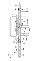
- FIG. FIG. 11 is a side view of a connecting portion between the fourth cross member and the side frame and the suspension device as seen from the outside in the vehicle width direction;
- Fig. 10 is a side view of the connecting portion between the rear portion of the fuel tank, the fourth cross member, and the side frame, viewed from the inside in the vehicle width direction;
- FIG. 11 is a plan view of a connecting portion between the fourth cross member and the side frame as viewed from above the vehicle;
- FIG. 10 is a bottom view of a connecting portion between the fourth cross member and the side frame and the suspension device as viewed from below the vehicle;
- a vehicle 10 is a frame vehicle 10 in which a chassis frame 12 supports a cab body (not shown) including a vehicle compartment in which an occupant rides as a vehicle body component.
- the frame vehicle 10 is a pickup truck in which a chassis frame 12 supports a cab body and a cargo box arranged at the rear of the cab body as vehicle body components.
- the chassis frame 12 includes a pair of side frames 20 and a plurality of cross members 22 , 24 , 26 , 28 and 30 .
- the pair of side frames 20 has a closed cross-sectional structure with a rectangular cross section including an upper surface portion 2002, an inner side surface portion 2004, an outer side surface portion 2006, and a lower surface portion 2008. , and extends in the longitudinal direction of the vehicle.
- the pair of side frames 20 includes a front side portion 20A extending rearward from the front end of the side frame 20, a front kick-up portion 20B inclined rearward and downward from the rear end of the front side portion 20A, and a front kick-up portion 20B extending from the rear end of the front side kick-up portion 20B.
- It has a central portion 20C extending rearward, a rear kick-up portion 20D extending rearward and upward from the rear end of the central portion 20C, and a rear side portion 20E extending rearward from the rear end of the rear kick-up portion 20D.
- An engine and transmission (not shown) and the front wheels 14 are arranged between the front portions of the pair of side frames 20 .
- a propeller shaft 36 for transmitting the power of the engine from the transmission to the rear wheels 16 is provided extending rearward in the central portion between the pair of side frames 20 in the vehicle width direction.
- a rear axle housing 18 , a rear wheel 16 and a fuel tank 38 are arranged between the rear portions of the pair of side frames 20 .
- the rear axle housing 18 accommodates a differential gear to which the propeller shaft 36 is connected, and supports a pair of (axle) axle shafts (not shown) connected to the differential gear and extending in the vehicle width direction.
- Rear wheels 16 are attached to hubs (not shown) provided at both ends of the axle shaft.
- the rear axle housing 18 is suspended from the chassis frame 12 by a rear suspension device 44 shown in FIG. Note that the rear suspension device 44 is omitted in FIG.
- the fuel tank 38 is made of synthetic resin or sheet metal, has an elongated shape, and is provided between the pair of side frames 20 with its longitudinal direction aligned with the vehicle front-rear direction. Specifically, the fuel tank 38 extends from behind the third cross member 26 to behind the fourth cross member 28 .
- a plurality of mounts 32 are provided on the pair of side frames 20, and the cab body (not shown) is supported from below via the mounts 32.
- the mounts 32 include a pair of first mounts 32A respectively located on the front kick-up portion 20B and a pair of second mounts 32B respectively located on the rear kick-up portion 20D. ing.
- a plurality of packing box support brackets 34 are provided at the rear portion of the pair of side frames 20, and support the packing box from below via the packing box support brackets 34.
- the packing box support brackets 34 are composed of a pair of first packing box support brackets 34A positioned at the rear kick-up portion 20D and a pair of second packing box support brackets 34B positioned at the rear side portion 20E. And prepare.
- the first and second packing box support brackets 34A, 34B are attached to the top of the rear kick-up section 20D and the rear side section 20E.
- the first packing box support bracket 34A will be described later in detail.
- the dimension between the lower surface portion 2008 and the upper surface portion 2002 of the rear kick-up portion 20D gradually decreases toward the rear.
- the inclination of the lower surface portion 2008 of the side frame 20 with respect to the horizontal plane is set larger than the inclination of the upper surface portion 2002 at the rear kick-up portion 20D.
- the rear portions of the side frames 20 ( In the present embodiment, the outer side surface portions 2006 positioned at the rear kick-up portion 20D and the rear side portion 20E are provided closer inward in the vehicle width direction than the outer side surface portions 2006 positioned at the front portion of the side frame 20.
- the rear outer side surface portion 2006 of the side frame 20 includes an inclined surface portion 2010 that inclines inward in the vehicle width direction as it goes rearward from the rear end of the front outer side surface portion 2006 of the side frame 20, and a rearward portion of the inclined surface portion 2010.
- a rear outer side surface portion 2006A (FIG.
- the rear suspension device 44 is of the leaf spring type.
- the front end of the leaf spring 46 is connected to the rear of the front end of the rear kick-up portion 20D.
- a rear end of the leaf spring 46 is connected to the rear side portion 20E.
- the front end of the inclined surface portion 2010 is positioned forward of the front end of the leaf spring 46 .
- the rear end of the inclined surface portion 2010 is positioned forward of the front end of the rear wheel 16 .
- the rear outer side portion 2006 ⁇ /b>A extends from the front of the front end of the rear wheel 16 to the rear end of the side frame 20 . Note that the rear outer side surface portion 2006A may be positioned within the range of the side frame 20 where the rear suspension device 44 is positioned at least in the longitudinal direction of the vehicle when viewed in plan, which will be described later.
- the plurality of cross members extend in the vehicle width direction at a plurality of locations spaced apart in the vehicle front-rear direction and connect the pair of side frames 20 .
- the plurality of cross members comprises five cross members, first, second, third, fourth and fifth cross members 22, 24, 26, 28 and 30, which are They are arranged in sequence from front to back.
- the first cross member 22 connects between the front side portions 20A of the pair of side frames 20 .
- the second and third cross members 24 and 26 connect between the central portions 20C of the pair of side frames 20.
- the fourth cross member 28 connects the rear side kick-up portions 20 ⁇ /b>D of the pair of side frames 20 .
- the fourth cross member 28 corresponds to the "cross member” in the claims
- the rear kick-up portion 20D corresponds to the "kick-up portion” in the claims.
- the fifth cross member 30 connects between the rear side portions 20E of the pair of side frames 20 .
- Vehicle front ends of the pair of side frames 20 are connected by a bumper beam 31 extending in the vehicle width direction, and a bumper fascia (not shown) is attached to the bumper beam 3134 .
- the rear suspension device 44 suspends the rear axle housing 18 (FIG. 5) from the chassis frame 12 (vehicle body).
- the rear suspension device 44 includes a pair of leaf springs 46 , a pair of shock absorbers 48 and a pair of bump rubbers 50 .
- the pair of leaf springs 46 are arranged below the pair of side frames 20, respectively.
- the front ends of the pair of leaf springs 46 are supported via spring brackets 54 on the lower portion of the rear kick-up portion 20D near the front end.
- the rear ends of the pair of leaf springs 46 are supported by the front portion of the rear side portion 20E via shackle links 56.
- intermediate portions of the pair of leaf springs 46 are connected to cylindrical portions 1802 on both sides of the rear axle housing 18 in the vehicle width direction via connecting tools 58 .
- the pair of shock absorbers 48 are connected at their lower ends to tubular portions 1802 of the rear axle housing 18 located inside the leaf springs 46 in the vehicle width direction. Upper ends of the pair of shock absorbers 48 are connected to the side frames 20 .
- the pair of bump rubbers 50 come into contact with the lower portion of the side frame 20 when an excessive load is applied to the rear axle housing 18 and the intermediate portion of the leaf spring 46 is greatly bent upward. This prevents the leaf springs 46 from coming into direct contact with the lower portions of the side frames 20 .
- the bump rubber 50 is attached to the upper surface of the leaf spring 46 and protrudes upward.
- a bump bracket 60 with which the upper end of the bump rubber 50 can abut is provided at the lower portion of the rear kick-up portion 20D. It is
- the front end of the rear suspension device 44 contacts the front end of the leaf spring 46, that is, the spring bracket 54, and the rear end of the rear suspension device 44 contacts the rear end of the leaf spring 46, that is, the shackle link 56.
- the range of the side frame 20 in which the rear suspension device 44 is positioned in the vehicle front-rear direction when viewed in plan is defined as the range from the point where the spring bracket 54 is provided on the side frame 20 to the point where the shackle link 56 is provided.
- FIGS. 2 and 5 a load input portion for inputting a load from the rear suspension device 44 to the side frame 20 will be described.
- the load input from the rear wheel 16 through the rear axle housing 18 to the leaf spring 46 from below is applied to the spring bracket 54 supporting the front end of the leaf spring 46 and the rear end of the leaf spring 46 .
- the load is input to the side frame 20 via two load input portions P1 and P2 with the shackle link 56 supporting the end.
- the two load input portions P1 and P2 are displaced outward in the vehicle width direction from the center of the side frame 20 in the width direction (indicated by the dashed line in the drawing). ing.
- the load input portion P3 is also applied to the side frame 20 in the same manner as the two load input portions P1 and P2. It is deviated to the outside in the vehicle width direction from the center in the width direction of the. Therefore, the load input to the side frame 20 via the leaf springs 46 and the bump bracket 60 is input to a portion deviated outward in the vehicle width direction from the center of the width of the side frame 20 in the vehicle width direction.
- a rear suspension device 44 is provided at a location where the rear outer side surface portion 2006A of the side frame 20 is located. is connected to the vehicle width direction outside of the center of the width of the side frame 20, and the center of the bump rubber 50 is more than the center of the width of the side frame 20 in the vehicle width direction. It is deviated to the outside in the vehicle width direction.
- the rear suspension device 44 is provided deviated outward in the vehicle width direction from the center of the width of the side frame 20 in the vehicle width direction.
- the load input portions P1, P2, and P3 are displaced outward in the vehicle width direction from the center of the width of the side frame 20 in the vehicle width direction.
- the fourth cross member 28 connects the vehicle front-rear direction intermediate portions of the rear kick-up portions 20D of the pair of side frames 20, and both ends of the fourth cross member 28 are respectively connected to the rear kick-up portions 20D. It is joined so as to pass through the up portion 20D.
- the fourth cross member 28 is formed of a pipe having a substantially rectangular cross-section with arc-shaped corners. Specifically, the fourth cross member 28 has four sections: an upwardly facing upper surface portion 2802 , a forwardly facing front surface portion 2804 , a rearwardly facing rear surface portion 2806 and a downwardly facing lower surface portion 2808 . a first cylindrical surface portion 2810 connecting the upper surface portion 2802 and the front surface portion 2804; a second cylindrical surface portion 2812 connecting the upper surface portion 2802 and the rear surface portion 2806; It has four cylindrical surface portions, a connecting third cylindrical surface portion 2814 and a fourth cylindrical surface portion 2816 connecting the rear surface portion 2806 and the lower surface portion 2808 .
- the first and second cylindrical surface portions 2810 and 2812 are formed with the same radius of curvature RA
- the third and fourth cylindrical surface portions 2814 and 2816 are formed with the same radius of curvature RB
- the first The radius of curvature RB of the third and fourth cylindrical surface portions 2814 and 2816 is larger than the radius of curvature RA of the second cylindrical surface portions 2810 and 2812 .
- the lower corner of the fourth cross member 28 has a larger radius of curvature than the upper corner.
- the fuel tank 38 extends rearward from the fourth cross member 28 .
- the rear portion of the fuel tank 38 is recessed downward so as to pass below the fourth cross member 28 (in this embodiment, the fuel tank 38 is positioned forward of the fourth cross member 28).
- a concave portion 3802 with a lower upper surface than the other portions is formed from the portion where the concave portion 3802 is formed to the rear end, and the front end portion of the concave portion 3802 is curved along the third cylindrical surface portion 2814 .
- the volume of the fuel tank 38 is reduced by forming the concave portion 3802, the radius of curvature RB of the third cylindrical surface portion 2814 is formed large, so the radius of curvature of the third cylindrical surface portion 2814 is formed small.
- the fourth cross member 28 is positioned within a range in which the rear suspension device 44 is positioned in the vehicle front-rear direction when viewed from above. Therefore, a load that pushes upward from the rear suspension device 44 is likely to be input to the fourth cross member 28 via the side frames 20 .
- a plurality of drain holes 2820 are formed in the lower surface portion 2808 of the fourth cross member 28 at intervals in the vehicle width direction along the center line of the lower surface portion 2808 in the vehicle front-rear direction. formed.
- a cable 62 for an in-vehicle device extending in a direction intersecting the extending direction of the fourth cross member 28 is placed. It is attached to the upper surface portion 2802 of the fourth cross member 28 via a fixture 64 such as a clamp.
- the above-described first packing box support bracket 34A is attached to a portion of the rear kick-up portion 20D located above the connecting portion to which the fourth cross member 28 is connected.
- the first packing box support bracket 34A corresponds to the "bracket" in the claims.
- the first packing box support bracket 34A includes a mounting surface portion 3402, a front surface portion 3404 and a rear surface portion 3406. As shown in FIGS. The front surface portion 3404 and the rear surface portion 3406 extend in the vertical direction of the vehicle and are connected to the upper surface portion 2002 of the rear kick-up portion 20D.
- the vehicle width direction outer end portions of the front surface portion 3404 and the rear surface portion 3406 extend below the upper surface portion 2002 of the rear kick-up portion 20D and are connected to the outer surface portion 2006 of the rear kick-up portion 20D.
- the lower end of the front surface portion 3404 is located in front of the first cylindrical surface portion 2810 of the fourth cross member 28, and the lower end of the rear surface portion 3406 is located above the second cylindrical surface portion 2812 of the fourth cross member 28. , and are connected to the rear kick-up portion 20D in the vicinity of the fourth cross member 28.
- the mounting surface portion 3402 extends to connect the front surface portion 3404 and the rear surface portion 3406 .
- the mounting surface portion 3402 is provided with a weld nut 3408 (FIG. 3) to which a bolt inserted through the packing box is fastened at the central portion 20C.
- the fourth cross member 28 connecting the pair of side frames 20 is formed of a pipe having a substantially square cross section with arc-shaped corners.
- the corner portion on the side of the vehicle is set to have a larger radius of curvature RB than the corner portion on the vehicle upper side. Since the fourth cross member 28 is formed to have a substantially square cross-section, the cross-sectional area of the fourth cross member 28 can be reduced while suppressing an increase in the diameter (distance between opposing surfaces) compared to when the cross section is circular. Since the size can be increased, it is advantageous in improving the torsional rigidity of the fourth cross member 28 without securing a large occupied space.
- the corner portion of the fourth cross member 28 on the lower side of the vehicle is set to have a radius of curvature RB larger than that of the corner portion on the upper side of the vehicle, the load input to the side frame 20 so as to push it up from below is applied to the side frame 20 . and the joint portion of the fourth cross member 28, the concentration of the load on the corner portion of the fourth cross member 28 on the vehicle lower side can be suppressed, and the fourth cross member 28 and the pair of side frames 20 This is advantageous in ensuring the durability of the joint. Therefore, it is advantageous in ensuring the torsional rigidity of the fourth cross member 28 and the durability of the joint portion with the pair of side frames 20 .
- Various peripheral devices are arranged below the fourth cross member 28, and the corner portion of the fourth cross member 28 on the lower side of the vehicle is set to have a larger radius of curvature RB than the corner portion on the upper side of the vehicle. Therefore, it is advantageous in securing a gap between the fourth cross member 28 and the peripheral device arranged therebelow.
- the pair of side frames 20 has rear kick-up portions 20D that slope upward toward the rear, and the fourth cross member 28 is connected to the rear kick-up portions 20D.
- the rear kick-up portion 20D is inclined, when a load is applied from below, the end portion of the rear kick-up portion 20D is easily deformed so as to rotate in the vertical direction.
- the center of the load input portion that inputs the load from below to the pair of side frames 20 (the midpoint of the line connecting P1 and P2) is located at the rear portion of the rear kick-up portion 20D, The rear end of the rear kick-up portion 20D is easily deformed so as to rotate upward.
- the load is easily applied to the fourth cross member 28 connected to the rear kick-up portion 20D.
- it is advantageous in ensuring the torsional rigidity of the fourth cross member 28 and the durability of the joint portion with the pair of side frames 20.
- the upper surface portion 2802 and the lower surface portion 2808 of the fourth cross member 28 extend in the horizontal direction, and the lower surface portion 2008 of the rear kick-up portion 20D is inclined upward toward the rear. Therefore, the dimension between the lower and rear corner of the fourth cross member 28 and the lower ridgeline of the rear kick-up portion 20D is short, and the load input to the side frame 20 from below is applied to the rear kick-up portion 20D.
- the inclination of the lower surface portion 2008 of the rear kick-up portion 20D is set larger than the inclination of the upper surface portion 2002, so that the upper and front corners of the fourth cross member 28 and the upper edge of the rear kick-up portion 20D, the dimension between the lower and rear corner of the fourth cross member 28 and the lower edge of the rear kick-up portion 20D is greater than Shorten.
- the lower and rear corners of the fourth cross member 28 are set to have a larger radius of curvature RB than the upper corners.
- a large dimension can be secured between the corner portion and the lower ridgeline of the rear kickup portion 20D, and it is located below the vehicle lower side of the fourth cross member 28 from the lower ridgeline of the rear kickup portion 20D. This is advantageous in suppressing the concentration of the load applied to the rear corner, and is more advantageous in ensuring the durability of the connecting portion between the fourth cross member 28 and the pair of side frames 20 .
- the rear suspension devices 44 are connected to the lower portions of the pair of side frames 20, respectively. located within the range.
- the fourth cross member 28 is easily transmitted with a load that is pushed upward from the rear suspension device 44 via the side frames 20 , so that the fourth cross member 28 and the pair of side frames 20 can easily be pushed up.
- a larger load is input to the joint.
- the lower corner of the fourth cross member 28 has a larger radius of curvature RB than the upper corner. Even if a large load is input to the connecting portion, the concentration of the load on the corner portion of the fourth cross member 28 on the vehicle lower side can be suppressed, and the connection between the fourth cross member 28 and the pair of side frames 20 can be suppressed. This is advantageous in ensuring the durability of the part.
- the rear suspension device 44 is provided so as to deviate outward from the center of the side frame 20 in the vehicle width direction. Therefore, when a load is input from the rear suspension device 44 to push the side frame 20 upward, the lower portion of the side frame 20 is twisted so as to rotate outward in the vehicle width direction. A concentrated load is applied to the corner portion of the member 28 on the lower side of the vehicle.
- the corner portion of the fourth cross member 28 on the lower side of the vehicle is set to have a larger radius of curvature RB than the corner portion on the upper side of the vehicle. Concentration of load can be suppressed.
- a first packing box support bracket 34A is attached to a portion of the side frame 20 located above the fourth cross member 28, and the first packing box support bracket 34A serves as a joint between the fourth cross member 28 and the side frame 20.
- the vicinity of the upper part is reinforced. Therefore, the strength and rigidity of the connecting portion between the fourth cross member 28 and the pair of side frames 20 are ensured, and durability is ensured even if the load concentrates on the corner portion of the fourth cross member 28 on the upper side of the vehicle. It is advantageous in securing Also, by using the first packing box support bracket 34A, there is no need to provide a dedicated reinforcing member, which is advantageous in terms of reducing the number of parts, the cost of the parts, and the weight.
- the drain hole 2820 is formed in the lower surface portion 2808 of the fourth cross member 28 , so that water, mud, etc. that has entered the inside of the fourth cross member 28 can be removed from the vehicle of the fourth cross member 28 . It becomes easier to guide the drain hole 2820 along the arc shape of the lower corner, and water, mud, etc. can be smoothly discharged downward from the lower surface portion 2808 .
- the radius of curvature RA of the arc-shaped corner portion of the fourth cross member 28 on the upper side of the vehicle is set small, a large area of the upper surface portion 2802 of the fourth cross member 28 is ensured. can. Therefore, it becomes easy to directly attach the cable 62 of the vehicle-mounted device to the upper surface portion 2802, and there is no need to provide the fourth cross member 28 with a dedicated bracket for attaching the cable 62 of the vehicle-mounted device, thereby reducing the number of parts and the cost of parts. is advantageous on the diagram.
- the chassis frame 12 has five cross members, ie, the first to fifth cross members 22, 24, 26, 28, and 30.
- the number of cross members is arbitrary. It is arbitrary to which cross member the present invention is applied.
- the case where the cross member (fourth cross member 28) connects the rear side kick-up portions 20D of the pair of side frames 20 has been described. It may connect between the kick-up portions 20B.
- the suspension device is of the leaf spring type has been described, but the suspension device may be of the coil spring type or the like.
- the range in which the suspension device is positioned in the longitudinal direction of the vehicle when viewed from above is the range from the connection point of the lower arm on the side frame to the connection point of the shock absorber. It is a range from the part facing the most forward position of the parts constituting the device to the part facing the most rearward position. Also, in the present embodiment, the case where the bracket attached to the upper part of the side frame 20 above the fourth cross member 28 is the first packing box support bracket 34A has been described, but the use of the bracket is not limited. do not have.
Abstract
Description
特許文献1には、このようなフレーム車両において、断面円形のパイプからなるクロスメンバの両端部が一対のサイドフレームを貫通して連結された車両構造が開示されている。
このような車両構造においてシャシフレームのねじれ剛性を高めるために、クロスメンバの直径を大きく確保して断面積を大きくすることが考えられる。 In a frame vehicle in which a cab body and a luggage box are supported by a chassis frame, the chassis frame includes a pair of side frames and a plurality of cross members connecting the pair of side frames.
Patent Literature 1 discloses a vehicle structure in which both ends of a cross member made of a pipe having a circular cross section are connected through a pair of side frames in such a frame vehicle.
In order to increase the torsional rigidity of the chassis frame in such a vehicle structure, it is conceivable to ensure a large diameter of the cross member to increase the cross-sectional area.
そこで、クロスメンバとして断面四角形状のパイプを用いることが考えられる。
すなわち、直径が同じであれば、四角形状のパイプは円形のパイプに比べて断面積が大きいため、クロスメンバとして断面四角形状のパイプを用いると、直径の増加を抑制しつつクロスメンバの断面積を大きくすることができる。
しかしながら、クロスメンバとして断面四角形状のパイプを用いると、サイドフレームはサスペンション装置を介して下方から上方に突き上げる方向の荷重が加わるため、クロスメンバと一対のサイドフレームとの結合部分において、クロスメンバの矩形状の角部のうち特に下方の角部に荷重が集中しやすくなり、耐久性が低下することが懸念される。
本発明は、上記事情に鑑みなされたものであり、クロスメンバと一対のサイドフレームとの結合部分のねじれ剛性と耐久性の双方を確保する上で有利な車体構造を提供することを目的とする。 However, the diameter of the cross member is restricted by the vertical dimension of the side frame, and the space to be secured between the vehicle-mounted parts arranged around the cross member and the cross member must be considered. There is a limit to increasing the diameter of the cross member.
Therefore, it is conceivable to use a pipe having a square cross section as the cross member.
That is, if the diameter is the same, a square pipe has a larger cross-sectional area than a circular pipe. can be increased.
However, when a pipe having a rectangular cross section is used as the cross member, the side frame receives a load in a direction pushing upward from below through the suspension device. Of the rectangular corners, the load tends to be concentrated particularly on the lower corners, and there is concern that the durability will be reduced.
SUMMARY OF THE INVENTION It is an object of the present invention to provide a vehicle body structure that is advantageous in securing both torsional rigidity and durability of the connecting portion between a cross member and a pair of side frames. .
また、本発明の一実施の形態は、前記一対のサイドフレームは、車両前後方向一方側に向かうにつれて上下方向一方側に傾斜するキックアップ部を有し、前記クロスメンバは、前記一対のサイドフレームの前記キックアップ部間を連結していることを特徴とする。
また、本発明の一実施の形態は、前記一対のサイドフレームの下部には、それぞれサスペンション装置が設けられ、前記クロスメンバは、平面視した場合に車両前後方向においてサスペンション装置が位置する範囲内に位置していることを特徴とする。
また、本発明の一実施の形態は、前記サスペンション装置から前記サイドフレームへの荷重入力部は、前記サイドフレームの車幅方向における幅の中心よりも車幅方向外側に偏位していることを特徴とする。
また、本発明の一実施の形態は、前記サイドフレームの前記クロスメンバの上方に位置する箇所にブラケットが設けられていることを特徴とする。
また、本発明の一実施の形態は、前記クロスメンバの下面には、水抜き孔が形成されることを特徴とする。
また、本発明の一実施の形態は、前記クロスメンバの上面には、車載機器のケーブルが固定されることを特徴とする。 In order to achieve the above object, one embodiment of the present invention provides a pair of side frames that are spaced apart in the vehicle width direction and extend in the vehicle front-rear direction, and a side frame that extends in the vehicle width direction and penetrates the pair of side frames. and a cross member that connects the pair of side frames and is formed of a pipe having a substantially square cross-section with arc-shaped corners. The corner is characterized by having a radius of curvature larger than that of the corner on the upper side of the vehicle.
Further, in one embodiment of the present invention, the pair of side frames has a kick-up portion that inclines to one side in the vertical direction toward one side in the vehicle front-rear direction, and the cross member comprises the pair of side frames. characterized by connecting between the kick-up portions of the
Further, in one embodiment of the present invention, a suspension device is provided at the lower portion of each of the pair of side frames, and the cross member is positioned within a range in which the suspension device is positioned in the vehicle front-rear direction when viewed from above. characterized by being located
In one embodiment of the present invention, the load input portion from the suspension device to the side frame is deviated outward in the vehicle width direction from the center of the width of the side frame in the vehicle width direction. Characterized by
Moreover, one embodiment of the present invention is characterized in that a bracket is provided at a portion of the side frame positioned above the cross member.
Moreover, one embodiment of the present invention is characterized in that a drain hole is formed in the lower surface of the cross member.
Moreover, one embodiment of the present invention is characterized in that a cable of an in-vehicle device is fixed to the upper surface of the cross member.
また、クロスメンバの車両下方側の角部は、車両上方側の角部より曲率半径が大きく設定されているので、サイドフレームに下方から突き上げるように入力する荷重がサイドフレームとクロスメンバの結合部分に加わった場合に、クロスメンバの車両下方側の角部に荷重が集中することを抑制でき、クロスメンバと一対のサイドフレームとの結合部分の耐久性を確保する上で有利となる。
また、本発明の一実施の形態によれば、クロスメンバがキックアップ部に接続されている場合に、クロスメンバの車両下方側の曲率半径が大きく設定された角部と、キックアップ部の剛性の高い下側稜線との上下方向の間の寸法を大きく確保することができるため、剛性の高い下側稜線からクロスメンバの車両下方側の角部に加わる荷重の集中を抑制する上で有利となり、クロスメンバと一対のサイドフレームとの結合部分の耐久性を確保する上でより有利となる。
また、本発明の一実施の形態によれば、サスペンション装置からクロスメンバと一対のサイドフレームとの結合部分に大きな荷重が入力する場合であっても、クロスメンバの車両下方側の角部は、車両上方側の角部より曲率半径が大きく設定されているので、クロスメンバと一対のサイドフレームとの結合部分の耐久性を確保する上で有利となる。
また、本発明の一実施の形態によれば、サイドフレームの下部が車幅方向外側に向かうようにねじれてクロスメンバの車両下方側の角部に対して荷重が集中して加わる場合であっても、クロスメンバの車両下方側の角部は、車両上方側の角部より曲率半径が大きく設定されているので、クロスメンバと一対のサイドフレームとの結合部分の耐久性を確保する上で有利となる。
また、本発明の一実施の形態によれば、サイドフレームのクロスメンバの上方に位置する箇所に設けられたブラケットにより、クロスメンバとサイドフレームの結合部分の上部周辺が補強されるため、クロスメンバの車両上方側の角部に対して荷重が集中しても、クロスメンバと一対のサイドフレームとの結合部分の耐久性を確保する上で有利となる。
また、本発明の一実施の形態によれば、クロスメンバ内部に侵入した水や泥などがクロスメンバの車両下方側の角部の円弧形状に沿って水抜き孔に導かれやすくなるため、水や泥などを下方に円滑に排出する上で有利となる。
また、本発明の一実施の形態によれば、クロスメンバの上面の面積を大きく確保できるため、専用の部品を追加することなく、上面に車載機器のケーブルを直接取り付けることができるため、部品点数および部品コストの削減を図る上で有利となる。 According to one embodiment of the present invention, the cross member that connects the pair of side frames is formed of a pipe having a substantially square cross section with arc-shaped corners, so that the diameter of the cross member is increased. This is advantageous in improving the torsional rigidity of the cross member without securing a large occupied space.
In addition, since the corners of the cross member on the lower side of the vehicle are set to have a larger radius of curvature than the corners on the upper side of the vehicle, the load input to the side frame as if pushing it up from below is applied to the connecting portion between the side frame and the cross member. When the load is applied to the lower side of the vehicle, the load can be prevented from being concentrated on the corner of the cross member, which is advantageous in ensuring the durability of the connecting portion between the cross member and the pair of side frames.
Further, according to one embodiment of the present invention, when the cross member is connected to the kick-up portion, the corner portion of the cross member on the lower side of the vehicle having a large radius of curvature and the rigidity of the kick-up portion It is possible to secure a large vertical dimension between the lower ridgeline with high rigidity, which is advantageous in suppressing the concentration of the load applied to the corners of the cross member on the lower side of the vehicle from the lower ridgeline, which has high rigidity. , it is more advantageous in ensuring the durability of the connecting portion between the cross member and the pair of side frames.
Further, according to the embodiment of the present invention, even when a large load is input from the suspension device to the connecting portion between the cross member and the pair of side frames, the corner portion of the cross member on the lower side of the vehicle is Since the radius of curvature is set larger than that of the corner portion on the upper side of the vehicle, it is advantageous in ensuring the durability of the connecting portion between the cross member and the pair of side frames.
Further, according to the embodiment of the present invention, even if the lower portion of the side frame is twisted outward in the vehicle width direction and the load is concentrated on the corner portion of the cross member on the lower side of the vehicle. Also, since the corner portion of the cross member on the lower side of the vehicle has a larger radius of curvature than the corner portion on the upper side of the vehicle, it is advantageous in ensuring the durability of the connecting portion between the cross member and the pair of side frames. becomes.
In addition, according to the embodiment of the present invention, the brackets provided at a portion of the side frame above the cross member reinforce the upper periphery of the connecting portion between the cross member and the side frame. Even if the load concentrates on the corner portion on the upper side of the vehicle, it is advantageous in securing the durability of the connecting portion between the cross member and the pair of side frames.
Further, according to the embodiment of the present invention, water or mud that has entered the inside of the cross member is easily guided to the drain hole along the arc shape of the corner of the cross member on the lower side of the vehicle. It is advantageous for smoothly discharging dirt and mud downward.
In addition, according to the embodiment of the present invention, since a large area can be secured for the upper surface of the cross member, cables of in-vehicle equipment can be directly attached to the upper surface without adding dedicated parts, thus reducing the number of parts. Also, it is advantageous in reducing the cost of parts.
なお、以下の図面において、符号FRは車両前方、符号UPは車両上方、符号HLは車幅方向を示す。
図1に示すように、本発明の実施の形態では、車両10が、車体構成部品として乗員が搭乗する車室を含む不図示のキャブボディをシャシフレーム12で支持するフレーム車両10である場合について説明する。
なお、本実施の形態では、フレーム車両10は、車体構成部品として、キャブボディと、キャブボディの後部に配置された荷箱と、をシャシフレーム12で支持するピックアップトラックである。 A vehicle structure according to an embodiment of the present invention will be described below with reference to the drawings.
In the drawings below, reference numeral FR indicates the front of the vehicle, UP indicates the upper side of the vehicle, and HL indicates the width direction of the vehicle.
As shown in FIG. 1, in the embodiment of the present invention, a
In this embodiment, the
一対のサイドフレーム20は、図2、図4に示すように、上面部2002、内側面部2004、外側面部2006、下面部2008を備えた断面矩形状の閉断面構造を呈しており、車幅方向に離間して配置され、車両前後方向に延在している。
一対のサイドフレーム20は、サイドフレーム20の前端から後方に延びる前側部20Aと、前側部20Aの後端から後方かつ下方に傾斜する前側キックアップ部20Bと、前側キックアップ部20Bの後端から後方に延びる中央部20Cと、中央部20Cの後端から後方かつ上方に延びる後側キックアップ部20Dと、後側キックアップ部20Dの後端から後方に延びる後側部20Eと、を備える。 The
As shown in FIGS. 2 and 4, the pair of
The pair of
トランスミッションからはエンジンの動力を後輪16に伝達するプロペラシャフト36が一対のサイドフレーム20間の車幅方向中央部において後方に延びて設けられている。
また、一対のサイドフレーム20の後部の間には、リアアクスルハウジング18、後輪16、燃料タンク38が配置されている。
リアアクスルハウジング18は、プロペラシャフト36が連結されたディファレンシャルギアを収容すると共に、ディファレンシャルギアに連結され車幅方向に延びた一対の(車軸)アクスルシャフト(不図示)を支持するものであり、一対のアクスルシャフトの両端に設けられたハブ(不図示)に後輪16が装着されている。そして、リアアクスルハウジング18は、図2に示すリアサスペンション装置44によってシャシフレーム12に懸架されている。なお、図1においてリアサスペンション装置44は図示省略している。
燃料タンク38は、合成樹脂製あるいは板金製であり、細長状を呈し、長手方向を車両前後方向に合わせて一対のサイドフレーム20の間に設けられている。詳細には、燃料タンク38は、第3クロスメンバ26の後方から第4クロスメンバ28の後方まで延びている。 An engine and transmission (not shown) and the
A
A
The
The
本実施の形態では、マウント32は、前側キックアップ部20Bにそれぞれ位置する一対の第1マウント32Aと、後側キックアップ部20Dにそれぞれ位置する一対の第2マウント32Bと、を含んで構成されている。 A plurality of
In this embodiment, the
本実施の形態では、荷箱支持ブラケット34は、後側キックアップ部20Dにそれぞれ位置する一対の第1荷箱支持ブラケット34Aと、後側部20Eに位置する一対の第2荷箱支持ブラケット34Bと、を備える。第1、第2荷箱支持ブラケット34A、34Bは、後側キックアップ部20Dと後側部20Eの上部に取り付けられている。
なお、第1荷箱支持ブラケット34Aについては後で詳細に説明する。 A plurality of packing
In the present embodiment, the packing
The first packing
詳細には、後側キックアップ部20Dにおいてサイドフレーム20の下面部2008の水平面に対する傾斜が上面部2002の傾斜に比較して大きく設定されている。
また、図5に示すように、サイドフレーム20の車幅方向外側に配置される後輪16とその周辺の車両構成部品に対してのサイドフレーム20の干渉を避けるため、サイドフレーム20の後部(本実施の形態においては後側キックアップ部20Dおよび後側部20E)に位置する外側面部2006は、サイドフレーム20の前部に位置する外側面部2006と比較して車幅方向内側に寄せて設けられている。
詳細には、サイドフレーム20の後部の外側面部2006は、サイドフレーム20の前部の外側面部2006の後端から後方に向かうにつれて車幅方向内側へ傾斜する傾斜面部2010と、傾斜面部2010の後端から後方に略直線状に延びる後部外側面部2006A(図2)とで形成され、一方、サイドフレーム20の後部の内側面部2004は車両前後方向に略直線状に延在している。
本実施の形態では、図5に示すように、リアサスペンション装置44はリーフスプリングタイプである。リーフスプリング46の前端は後側キックアップ部20Dの前端よりも後方に接続される。リーフスプリング46の後端は後側部20Eに接続されている。そして、傾斜面部2010の前端はリーフスプリング46の前端よりも前方に位置する。傾斜面部2010の後端は後輪16の前端より前方に位置する。後部外側面部2006Aは後輪16の前端より前方からサイドフレーム20の後端まで延びる。
なお、後部外側面部2006Aは、少なくとも後述する平面視した場合に車両前後方向においてリアサスペンション装置44が位置するサイドフレーム20の範囲に位置していればよい。 As shown in FIG. 2, in the pair of side frames 20, the dimension between the
Specifically, the inclination of the
In addition, as shown in FIG. 5, in order to avoid interference of the side frames 20 with the
Specifically, the rear outer
In this embodiment, as shown in FIG. 5, the
Note that the rear outer
本実施の形態では、複数のクロスメンバは、第1、第2、第3、第4、第5クロスメンバ22、24、26、28、30の5つのクロスメンバを含んで構成され、それらの順番で前方から後方に並べられて配置されている。
本実施の形態では、第1クロスメンバ22は、一対のサイドフレーム20の前側部20A間を連結している。
第2、第3クロスメンバ24、26は、一対のサイドフレーム20の中央部20C間を連結している。
また、第4クロスメンバ28は、一対のサイドフレーム20の後側キックアップ部20D間を連結している。本実施の形態では、第4クロスメンバ28が特許請求の範囲の「クロスメンバ」に相当しており、後側キックアップ部20Dが特許請求の範囲の「キックアップ部」に相当している。
また、第5クロスメンバ30は、一対のサイドフレーム20の後側部20E間を連結している。
また、一対のサイドフレーム20の車両前端は、車幅方向に延在するバンパビーム31で連結され、バンパビーム3134には不図示のバンパフェイシャが取り付けられる。 As shown in FIG. 1 , the plurality of cross members extend in the vehicle width direction at a plurality of locations spaced apart in the vehicle front-rear direction and connect the pair of side frames 20 .
In this embodiment, the plurality of cross members comprises five cross members, first, second, third, fourth and
In this embodiment, the
The second and
Also, the
Also, the
Vehicle front ends of the pair of side frames 20 are connected by a
本実施の形態では、リアサスペンション装置44は、一対のリーフスプリング46と、一対のショックアブソーバ48と、一対のバンプラバー50と、を含む。
一対のリーフスプリング46は、一対のサイドフレーム20の下方にそれぞれ配置されている。一対のリーフスプリング46の前端は、スプリングブラケット54を介して後側キックアップ部20Dの前端寄りの下部に支持される。一対のリーフスプリング46の後端は、シャックルリンク56を介して後側部20Eの前部に支持されている。
図2,図5に示すように、一対のリーフスプリング46の中間部は、連結具58を介してリアアクスルハウジング18の車幅方向両側の筒部1802に連結されている。 As shown in FIG. 2, the
In this embodiment, the
The pair of
As shown in FIGS. 2 and 5 , intermediate portions of the pair of
一対のショックアブソーバ48の上端は、サイドフレーム20に連結されている。 As shown in FIG. 2 , the pair of
Upper ends of the pair of
バンプラバー50は、リーフスプリング46の上面に取り付けられ上方に向かって突設されている。
後側キックアップ部20Dの下部には、バンプラバー50の上端が当接可能なバンプブラケット60が設けられており、バンプラバー50の上端がバンプブラケット60の下部に安定して当接するように図られている。 As shown in FIG. 2, the pair of
The
A
図2、図5に示すように、後輪16からリアアクスルハウジング18を介してリーフスプリング46に下方から入力する荷重は、リーフスプリング46の前端を支持するスプリングブラケット54と、リーフスプリング46の後端を支持するシャックルリンク56との2箇所の荷重入力部P1、P2を介してサイドフレーム20に入力する。
図5に示すように、平面視した状態で、2箇所の荷重入力部P1、P2は、サイドフレーム20の幅方向の中心(図中一点鎖線で図示)よりも車幅方向外側に偏位している。
また、バンプラバー50がバンプブラケット60に当接することでサイドフレーム20に荷重が入力するが、この際の荷重入力部P3も、上記の2つの荷重入力部P1、P2と同様に、サイドフレーム20の幅方向の中心よりも車幅方向外側に偏位している。
したがって、リーフスプリング46およびバンプブラケット60を介してサイドフレーム20に入力される荷重は、サイドフレーム20の車幅方向における幅の中心よりも車幅方向外側に偏位した箇所に入力される。 Here, a load input portion for inputting a load from the
As shown in FIGS. 2 and 5 , the load input from the
As shown in FIG. 5, in plan view, the two load input portions P1 and P2 are displaced outward in the vehicle width direction from the center of the
Also, when the
Therefore, the load input to the
後輪16およびその周辺の車両構成部品とサイドフレーム20との干渉を避けるため、リアサスペンション装置44がサイドフレーム20の後部外側面部2006Aが位置する箇所に設けられ、リーフスプリング46とサイドフレーム20とが結合される箇所が、サイドフレーム20の車幅方向における幅の中心よりも車幅方向外側に偏位し、また、バンプラバー50の中心がサイドフレーム20の車幅方向における幅の中心よりも車幅方向外側に偏位している。言い換えると、リアサスペンション装置44は、サイドフレーム20の車幅方向における幅の中心よりも車幅方向外側に偏位して設けられている。
このような理由により、荷重入力部P1、P2、P3は、サイドフレーム20の車幅方向における幅の中心よりも車幅方向外側に偏位していることから、リアサスペンション装置44を介して下方から突き上げるような荷重が荷重入力部P1、P2、P3に入力すると、サイドフレーム20はその下部が車幅方向外側に向かってねじれるように回転することになる。 Here, the reason why the load input portions P1, P2, and P3 are displaced outward in the vehicle width direction from the center of the width of the
In order to avoid interference between the
For this reason, the load input portions P1, P2, and P3 are displaced outward in the vehicle width direction from the center of the width of the
図2に示すように、第4クロスメンバ28は、一対のサイドフレーム20の後側キックアップ部20Dの車両前後方向中間部分を連結しており、第4クロスメンバ28の両端はそれぞれ後側キックアップ部20Dを貫通するように接合されている。 Next, the
As shown in FIG. 2, the
具体的には、第4クロスメンバ28は、上方を向いた上面部2802と、前方を向いた前面部2804と、後方を向いた後面部2806と、下方を向いた下面部2808と、の4つの平面部と、上面部2802と前面部2804とを接続する第1円筒面部2810と、上面部2802と後面部2806とを接続する第2円筒面部2812と、前面部2804と下面部2808とを接続する第3円筒面部2814と、後面部2806と下面部2808とを接続する第4円筒面部2816と、の4つの円筒面部とを有している。
本実施の形態では、第1、第2円筒面部2810、2812は同一の曲率半径RAで形成され、第3、第4円筒面部2814、2816は同一の曲率半径RBで形成されており、第1、第2円筒面部2810、2812の曲率半径RAよりも第3、第4円筒面部2814、2816の曲率半径RBが大きな値となっている。
言い換えると、第4クロスメンバ28の下方側の角部は、上方側の角部より曲率半径が大きく設定されている。 As shown in FIG. 3, the
Specifically, the
In this embodiment, the first and second
In other words, the lower corner of the
凹部3802が形成されることで燃料タンク38の容積が削減されるものの、第3円筒面部2814の曲率半径RBが大きく形成されているため、第3円筒面部2814の曲率半径が小さく形成される場合に比較して燃料タンク38の容積を確保する上で有利となっている。
また、燃料タンク38が膨張した際に燃料タンク38の角部に負荷がかかるが、このとき、凹部3802前端の湾曲にも同様に負荷がかかることになる。第4クロスメンバ28の下方側の角部(第3円筒面部2814)の曲率半径RBが大きく形成されているため、凹部3802前端の湾曲の曲率半径も大きくすることができ、荷重が集中することを抑制できる。 As already mentioned, the
Although the volume of the
Further, when the
したがって、第4クロスメンバ28には、リアサスペンション装置44から上方に突き上げるような荷重がサイドフレーム20を介して入力されやすくなることになる。 As shown in FIGS. 2 and 5, the
Therefore, a load that pushes upward from the
図4に示すように、第4クロスメンバ28の上面部2802には、第4クロスメンバ28の延在方向と交差する方向に延在する車載機器のケーブル62が載置され、このケーブル62がクランプなどの取付具64を介して第4クロスメンバ28の上面部2802に取り付けられている。 As shown in FIGS. 3 and 5, a plurality of
As shown in FIG. 4, on the
図2、図3、図4に示すように、第1荷箱支持ブラケット34Aは、取り付け面部3402と、前面部3404と、後面部3406と、を備えている。
前面部3404および後面部3406は、車両上下方向に延び後側キックアップ部20Dの上面部2002に接続される。また、前面部3404および後面部3406の車幅方向外側端部は、後側キックアップ部20Dの上面部2002より下方まで延び、後側キックアップ部20Dの外側面部2006に接続される。
本実施の形態では、前面部3404の下端部は第4クロスメンバ28の第1円筒面部2810の前方に位置し、後面部3406の下端部は第4クロスメンバ28の第2円筒面部2812の上方に位置し、それぞれは第4クロスメンバ28近傍で後側キックアップ部20Dに接続されている。
取り付け面部3402は、前面部3404と後面部3406とを繋ぐように延びている。
取り付け面部3402には、その中央部20Cに荷箱を挿通したボルトが締結されるウェルドナット3408(図3)が設けられている。 As shown in FIG. 1, the above-described first packing
As shown in FIGS. 2, 3 and 4, the first packing
The
In this embodiment, the lower end of the
The mounting
The mounting
本実施の形態によれば、一対のサイドフレーム20を連結する第4クロスメンバ28が、角部が円弧状に湾曲された断面略四角形状のパイプで形成され、第4クロスメンバ28の車両下方側の角部は、車両上方側の角部より曲率半径RBが大きく設定されている。
第4クロスメンバ28が断面略四角形状に形成されているので、断面を円形にした場合に比べ、直径(対向する面間の距離)の増加を抑制しつつ第4クロスメンバ28の断面積を大きくすることができるため、大きな占有スペースを確保することなく、第4クロスメンバ28のねじれ剛性の向上を図る上で有利となる。
また、第4クロスメンバ28の車両下方側の角部は、車両上方側の角部より曲率半径RBが大きく設定されているので、サイドフレーム20に下方から突き上げるように入力する荷重がサイドフレーム20と第4クロスメンバ28の結合部分に加わった場合に、第4クロスメンバ28の車両下方側の角部に荷重が集中することを抑制でき、第4クロスメンバ28と一対のサイドフレーム20との結合部分の耐久性を確保する上で有利となる。
したがって、第4クロスメンバ28のねじれ剛性および一対のサイドフレーム20との結合部分の耐久性を確保する上で有利となる。
また、第4クロスメンバ28の下方には、様々な周辺機器が配置されるが、第4クロスメンバ28の車両下方側の角部は、車両上方側の角部より曲率半径RBが大きく設定されているので、第4クロスメンバ28とその下方に配置する周辺機器との間に隙間を確保する上で有利となる。 Next, functions and effects will be described.
According to the present embodiment, the
Since the
In addition, since the corner portion of the
Therefore, it is advantageous in ensuring the torsional rigidity of the
Various peripheral devices are arranged below the
後側キックアップ部20Dは傾斜しているため、下方から荷重が入力された際にその端部が上下方向へ回転するように変形しやすくなっている。本実施の形態では、一対のサイドフレーム20に下方から荷重を入力する荷重入力部の中心(P1、P2を結ぶ線の中点)が後側キックアップ部20Dの後部に位置しているため、後側キックアップ部20Dの後端が上方へ向かい回転するように変形しやすくなっている。このため、後側キックアップ部20Dに接続される第4クロスメンバ28には荷重が入力され易くなっている。
本実施の形態によれば、第4クロスメンバ28のねじれ剛性および一対のサイドフレーム20との結合部分の耐久性を確保する上で有利となるため、後側キックアップ部20Dに接続されるクロスメンバとして有利である。
また、本実施の形態では、第4クロスメンバ28の上面部2802および下面部2808が水平方向に延びており、後側キックアップ部20Dの下面部2008が後方に向かうにつれて上方に傾斜しているので、第4クロスメンバ28の下方側かつ後方側の角部と後側キックアップ部20Dの下側稜線との間の寸法は短いものとなり、サイドフレーム20に下方から入力する荷重が後側キックアップ部20Dの下側稜線から第4クロスメンバ28の車両下方側でかつ車両後方側の角部に集中しやすくなる。特に、本実施の形態では、後側キックアップ部20Dの下面部2008の傾斜が上面部2002の傾斜に比較して大きく設定されているので、第4クロスメンバ28の上方側かつ前方側の角部と後側キックアップ部20Dの上側稜線との間の寸法に比べ、第4クロスメンバ28の下方側かつ後方側の角部と後側キックアップ部20Dの下側稜線との間の寸法が短くなる。
本実施の形態では、第4クロスメンバ28の下方側かつ後方側の角部が上方側の角部より曲率半径RBが大きく設定されているので、第4クロスメンバ28の下方側かつ後方側の角部と、後側キックアップ部20Dの下側稜線との間の寸法を大きく確保することができ、後側キックアップ部20Dの下側稜線から第4クロスメンバ28の車両下方側でかつ車両後方側の角部に加わる荷重の集中を抑制する上で有利となり、第4クロスメンバ28と一対のサイドフレーム20との結合部分の耐久性を確保する上でより有利となる。 In addition, in the present embodiment, the pair of side frames 20 has rear kick-up
Since the rear kick-up
According to the present embodiment, it is advantageous in ensuring the torsional rigidity of the
Further, in this embodiment, the
In the present embodiment, the lower and rear corners of the
第4クロスメンバ28には、リアサスペンション装置44からサイドフレーム20を介して上方に突き上げるように入力する荷重が伝達され易くなっていることから、第4クロスメンバ28と一対のサイドフレーム20との結合部分により大きな荷重が入力する。
本実施の形態によれば、第4クロスメンバ28の下方側の角部は上方側の角部より曲率半径RBが大きく設定されているので、第4クロスメンバ28と一対のサイドフレーム20との結合部分に大きな荷重が入力する場合であっても、第4クロスメンバ28の車両下方側の角部に荷重が集中することを抑制でき、第4クロスメンバ28と一対のサイドフレーム20との結合部分の耐久性を確保する上で有利となる。 Further, in the present embodiment, the
The
According to the present embodiment, the lower corner of the
したがって、リアサスペンション装置44からサイドフレーム20に対して上方に突き上げるような荷重が入力されたとき、サイドフレーム20はその下部が車幅方向外側に向かい回転するようにねじれ、これにより、第4クロスメンバ28の車両下方側の角部に対して荷重が集中して加わることになる。
本実施の形態では、第4クロスメンバ28の車両下方側の角部が車両上方側の角部より曲率半径RBが大きく設定されているので、第4クロスメンバ28の車両下方側の角部に荷重が集中することを抑制できる。 In addition, in the present embodiment, the
Therefore, when a load is input from the
In the present embodiment, the corner portion of the
したがって、第4クロスメンバ28と一対のサイドフレーム20との結合部分の強度剛性が確保されており、第4クロスメンバ28の車両上方側の角部に対して荷重が集中しても耐久性を確保する上で有利となる。
また、第1荷箱支持ブラケット34Aを利用することで、専用の補強用部材を設ける必要がないため、部品点数および部品コストの低減、軽量化を図る上で有利となる。 A first packing
Therefore, the strength and rigidity of the connecting portion between the
Also, by using the first packing
そのため、車載機器のケーブル62を上面部2802に直接取り付けることが容易となり、車載機器のケーブル62を取り付けるための専用のブラケットを第4クロスメンバ28に設ける必要がなく、部品点数および部品コストの削減を図上で有利となる。 In addition, in the present embodiment, since the radius of curvature RA of the arc-shaped corner portion of the
Therefore, it becomes easy to directly attach the
また、本実施の形態では、クロスメンバ(第4クロスメンバ28)が一対のサイドフレーム20の後側キックアップ部20D間を連結する場合について説明したが、クロスメンバは一対のサイドフレーム20の前側キックアップ部20B間を連結するものであってもよい。
また、本実施の形態では、サスペンション装置がリーフスプリングタイプである場合について説明したが、サスペンション装置はコイルスプリングタイプ等であってもよい。サスペンション装置がコイルスプリングタイプである場合、平面視した場合に車両前後方向においてサスペンション装置が位置する範囲は、サイドフレームにおけるロアアームの接続箇所からショックアブソーバの接続箇所までの範囲等、サイドフレームにおける、サスペンション装置を構成する部品の最も前方に位置する箇所に対向する部分から最も後方に位置する箇所に対向する部分までの範囲となる。
また、本実施の形態では、第4クロスメンバ28の上方でサイドフレーム20の上部に取り付けられるブラケットが第1荷箱支持ブラケット34Aである場合について説明したが、ブラケットの用途は限定されるものではない。 In this embodiment, the
Further, in the present embodiment, the case where the cross member (fourth cross member 28) connects the rear side kick-up
Moreover, in the present embodiment, the case where the suspension device is of the leaf spring type has been described, but the suspension device may be of the coil spring type or the like. When the suspension device is of the coil spring type, the range in which the suspension device is positioned in the longitudinal direction of the vehicle when viewed from above is the range from the connection point of the lower arm on the side frame to the connection point of the shock absorber. It is a range from the part facing the most forward position of the parts constituting the device to the part facing the most rearward position.
Also, in the present embodiment, the case where the bracket attached to the upper part of the
12 シャシフレーム
14 前輪
16 後輪
18 リアアクスルハウジング
1802 筒部
20 サイドフレーム
20A 前側部
20B 前側キックアップ部
20C 中央部
20D 後側キックアップ部(キックアップ部)
20E 後側部
2002 上面部
2004 内側面部
2006 外側面部
2006A 後部外側面部
2008 下面部
2010 傾斜面部
22 第1クロスメンバ
24 第2クロスメンバ
26 第3クロスメンバ
28 第4クロスメンバ(クロスメンバ)
2802 上面部
2804 前面部
2806 後面部
2808 下面部
2810 第1円筒面部
2812 第2円筒面部
2814 第3円筒面部
2816 第4円筒面部
2820 水抜き孔
30 第5クロスメンバ
31 バンパビーム
32 マウント
32A 第1マウント
32B 第2マウント
34 荷箱支持ブラケット
34A 第1荷箱支持ブラケット
3402 取り付け面部
3404 前面部
3406 後面部
3408 ウェルドナット
34B 第2荷箱支持ブラケット
36 プロペラシャフト
38 燃料タンク
3802 凹部
44 リアサスペンション装置
46 リーフスプリング
48 ショックアブソーバ
50 バンプラバー
54 スプリングブラケット
56 シャックルリンク
58 連結具
60 バンプブラケット
62 ケーブル
64 取付具
P1、P2、P3 荷重入力部 10
20E
2802
Claims (7)
- 車幅方向に離間して配置され車両前後方向に延びる一対のサイドフレームと、
車幅方向に延び前記一対のサイドフレームを貫通して設けられ前記一対のサイドフレームを連結するクロスメンバと、を備え、
前記クロスメンバは、角部が円弧状に湾曲された断面略四角形状のパイプで形成され、
前記クロスメンバの車両下方側の角部は、車両上方側の角部より曲率半径が大きく設定されている、
ことを特徴とする車両構造。 a pair of side frames that are spaced apart in the vehicle width direction and extend in the vehicle front-rear direction;
a cross member that extends in the vehicle width direction and is provided through the pair of side frames to connect the pair of side frames;
The cross member is formed of a pipe having a substantially rectangular cross section with arc-shaped corners,
The corner portion of the cross member on the lower side of the vehicle is set to have a larger radius of curvature than the corner portion on the upper side of the vehicle.
A vehicle structure characterized by: - 前記一対のサイドフレームは、車両前後方向一方側に向かうにつれて上下方向一方側に傾斜するキックアップ部を有し、
前記クロスメンバは、前記一対のサイドフレームの前記キックアップ部間を連結している、
ことを特徴とする請求項1に記載の車両構造。 The pair of side frames has a kick-up portion that inclines to one side in the vertical direction toward the one side in the vehicle front-rear direction,
The cross member connects between the kick-up portions of the pair of side frames,
The vehicle structure according to claim 1, characterized in that: - 前記一対のサイドフレームの下部には、それぞれサスペンション装置が設けられ、
前記クロスメンバは、平面視した場合に車両前後方向においてサスペンション装置が位置する範囲内に位置している、
ことを特徴とする請求項1又は2に記載の車両構造。 Suspension devices are provided at the lower portions of the pair of side frames, respectively,
The cross member is positioned within a range in which the suspension device is positioned in the longitudinal direction of the vehicle when viewed in plan.
The vehicle structure according to claim 1 or 2, characterized in that: - 前記サスペンション装置から前記サイドフレームへの荷重入力部は、前記サイドフレームの車幅方向における幅の中心よりも車幅方向外側に偏位している、
ことを特徴とする請求項3に記載の車両構造。 A load input portion from the suspension device to the side frame is deviated outward in the vehicle width direction from the center of the width of the side frame in the vehicle width direction.
The vehicle structure according to claim 3, characterized in that: - 前記サイドフレームの前記クロスメンバの上方に位置する箇所にブラケットが設けられている、
ことを特徴とする請求項1から4のいずれか1項に記載の車両構造。 A bracket is provided at a portion of the side frame located above the cross member,
The vehicle structure according to any one of claims 1 to 4, characterized in that: - 前記クロスメンバの下面には、水抜き孔が形成される、
ことを特徴とする請求項1から5のいずれか1項に記載の車両構造。 A drain hole is formed in the lower surface of the cross member,
The vehicle structure according to any one of claims 1 to 5, characterized in that: - 前記クロスメンバの上面には、車載機器のケーブルが固定される、
ことを特徴とする請求項1から6のいずれか1項に記載の車両構造。 A cable of an in-vehicle device is fixed to the upper surface of the cross member,
The vehicle structure according to any one of claims 1 to 6, characterized in that:
Priority Applications (2)
| Application Number | Priority Date | Filing Date | Title |
|---|---|---|---|
| BR112023019651A BR112023019651A2 (en) | 2021-03-30 | 2022-02-01 | VEHICLE STRUCTURE |
| JP2023510554A JPWO2022209254A1 (en) | 2021-03-30 | 2022-02-01 |
Applications Claiming Priority (2)
| Application Number | Priority Date | Filing Date | Title |
|---|---|---|---|
| JP2021056536 | 2021-03-30 | ||
| JP2021-056536 | 2021-03-30 |
Publications (1)
| Publication Number | Publication Date |
|---|---|
| WO2022209254A1 true WO2022209254A1 (en) | 2022-10-06 |
Family
ID=83458653
Family Applications (1)
| Application Number | Title | Priority Date | Filing Date |
|---|---|---|---|
| PCT/JP2022/003904 WO2022209254A1 (en) | 2021-03-30 | 2022-02-01 | Vehicle structure |
Country Status (3)
| Country | Link |
|---|---|
| JP (1) | JPWO2022209254A1 (en) |
| BR (1) | BR112023019651A2 (en) |
| WO (1) | WO2022209254A1 (en) |
Citations (5)
| Publication number | Priority date | Publication date | Assignee | Title |
|---|---|---|---|---|
| JPS62161085U (en) * | 1986-04-02 | 1987-10-13 | ||
| JPH0444463Y2 (en) * | 1986-09-25 | 1992-10-20 | ||
| WO2011101906A1 (en) * | 2010-02-18 | 2011-08-25 | フォード グローバル テクノロジーズ、リミテッド ライアビリティ カンパニー | Vehicular structure capable of absorbing energy of head-on collision |
| JP2019031210A (en) * | 2017-08-09 | 2019-02-28 | マツダ株式会社 | Harness wiring structure in engine room |
| JP2019093885A (en) * | 2017-11-22 | 2019-06-20 | トヨタ自動車株式会社 | Frame structure for vehicle |
-
2022
- 2022-02-01 BR BR112023019651A patent/BR112023019651A2/en unknown
- 2022-02-01 WO PCT/JP2022/003904 patent/WO2022209254A1/en active Application Filing
- 2022-02-01 JP JP2023510554A patent/JPWO2022209254A1/ja active Pending
Patent Citations (5)
| Publication number | Priority date | Publication date | Assignee | Title |
|---|---|---|---|---|
| JPS62161085U (en) * | 1986-04-02 | 1987-10-13 | ||
| JPH0444463Y2 (en) * | 1986-09-25 | 1992-10-20 | ||
| WO2011101906A1 (en) * | 2010-02-18 | 2011-08-25 | フォード グローバル テクノロジーズ、リミテッド ライアビリティ カンパニー | Vehicular structure capable of absorbing energy of head-on collision |
| JP2019031210A (en) * | 2017-08-09 | 2019-02-28 | マツダ株式会社 | Harness wiring structure in engine room |
| JP2019093885A (en) * | 2017-11-22 | 2019-06-20 | トヨタ自動車株式会社 | Frame structure for vehicle |
Also Published As
| Publication number | Publication date |
|---|---|
| JPWO2022209254A1 (en) | 2022-10-06 |
| BR112023019651A2 (en) | 2023-10-31 |
Similar Documents
| Publication | Publication Date | Title |
|---|---|---|
| US11161549B2 (en) | Vehicle body rear structure | |
| US9096276B2 (en) | Front subframe structure of automobile | |
| JP4774976B2 (en) | Rear body structure of the vehicle | |
| US8894134B2 (en) | Front body of vehicle | |
| US11097679B2 (en) | Vehicle body rear structure | |
| JP5119817B2 (en) | Car suspension system | |
| JP5870673B2 (en) | Front subframe structure of automobile | |
| JP5870680B2 (en) | Front subframe structure of automobile | |
| CN112124427B (en) | Vehicle structure of frame type vehicle | |
| US10239558B2 (en) | Vehicle lower section structure | |
| JPH07246949A (en) | Automotive subframe | |
| CN114620141A (en) | Vehicle body | |
| CN108974125B (en) | Suspension arm support structure | |
| WO2022209254A1 (en) | Vehicle structure | |
| JP3487213B2 (en) | Vehicle subframe structure | |
| US10577021B2 (en) | Vehicle sub-frame | |
| JP5913885B2 (en) | Rear suspension structure of automobile | |
| JP5151778B2 (en) | Vehicle suspension subframe | |
| US7370871B2 (en) | Vehicle frame with shock absorbing system | |
| JP3443818B2 (en) | Lower body structure of vehicle | |
| JPH10218012A (en) | Frame structure for superlow floor bus | |
| JP7332061B2 (en) | vehicle frame structure | |
| KR102453129B1 (en) | Sub frame for electiric vehicle | |
| WO2023181248A1 (en) | Vehicle frame structure | |
| WO2023189864A1 (en) | De dion-type suspension device |
Legal Events
| Date | Code | Title | Description |
|---|---|---|---|
| 121 | Ep: the epo has been informed by wipo that ep was designated in this application |
Ref document number: 22779483 Country of ref document: EP Kind code of ref document: A1 |
|
| DPE1 | Request for preliminary examination filed after expiration of 19th month from priority date (pct application filed from 20040101) | ||
| ENP | Entry into the national phase |
Ref document number: 2023510554 Country of ref document: JP Kind code of ref document: A |
|
| WWE | Wipo information: entry into national phase |
Ref document number: 2301006290 Country of ref document: TH |
|
| WWE | Wipo information: entry into national phase |
Ref document number: 18285187 Country of ref document: US |
|
| REG | Reference to national code |
Ref country code: BR Ref legal event code: B01A Ref document number: 112023019651 Country of ref document: BR |
|
| ENP | Entry into the national phase |
Ref document number: 112023019651 Country of ref document: BR Kind code of ref document: A2 Effective date: 20230925 |
|
| NENP | Non-entry into the national phase |
Ref country code: DE |
|
| 122 | Ep: pct application non-entry in european phase |
Ref document number: 22779483 Country of ref document: EP Kind code of ref document: A1 |