WO2023181140A1 - 市場取引管理システム、市場取引管理プログラムおよび市場取引管理方法 - Google Patents
市場取引管理システム、市場取引管理プログラムおよび市場取引管理方法 Download PDFInfo
- Publication number
- WO2023181140A1 WO2023181140A1 PCT/JP2022/013325 JP2022013325W WO2023181140A1 WO 2023181140 A1 WO2023181140 A1 WO 2023181140A1 JP 2022013325 W JP2022013325 W JP 2022013325W WO 2023181140 A1 WO2023181140 A1 WO 2023181140A1
- Authority
- WO
- WIPO (PCT)
- Prior art keywords
- transaction
- information
- product
- identifier
- user
- Prior art date
- Legal status (The legal status is an assumption and is not a legal conclusion. Google has not performed a legal analysis and makes no representation as to the accuracy of the status listed.)
- Ceased
Links
Images










Classifications
-
- G—PHYSICS
- G06—COMPUTING OR CALCULATING; COUNTING
- G06Q—INFORMATION AND COMMUNICATION TECHNOLOGY [ICT] SPECIALLY ADAPTED FOR ADMINISTRATIVE, COMMERCIAL, FINANCIAL, MANAGERIAL OR SUPERVISORY PURPOSES; SYSTEMS OR METHODS SPECIALLY ADAPTED FOR ADMINISTRATIVE, COMMERCIAL, FINANCIAL, MANAGERIAL OR SUPERVISORY PURPOSES, NOT OTHERWISE PROVIDED FOR
- G06Q30/00—Commerce
- G06Q30/06—Buying, selling or leasing transactions
Definitions
- the present invention relates to a market transaction management system, a market transaction management program, and a market transaction management method.
- Patent Document 1 According to the system described in Patent Document 1, by rewriting the owners of products that arrive on the market, it becomes possible to know who owns each product as a result of a transaction. However, as the owner is rewritten, it is not possible to understand the transaction process after the fact.
- the present invention has been made in consideration of the above-mentioned circumstances, and its purpose is to grasp the process of trading of circulating products after the fact in a product transaction management system in a market where products are circulated from time to time.
- one aspect of the present invention is a market transaction management system that manages information related to product transactions in a market
- the system includes a transaction information storage unit that stores information related to product transactions, and a transaction information storage unit that stores information related to product transactions; an input screen information providing section that provides information for displaying an information input screen that accepts input of information to be stored in the storage section; and an input screen information providing section that provides information for displaying an information input screen that accepts input of information to be stored in the storage section; and a transaction information storage processing unit that stores transaction information, and the transaction information storage unit stores, for each transaction, a transaction identifier that identifies the transaction, a seller identifier that identifies the seller of the product, and a seller identifier that identifies the buyer of the product.
- a buyer identifier for identification, transaction details that are information regarding the contents of the transaction, and a parent transaction identifier for identifying the transaction when the seller purchases the product to be traded are stored in association with each other.
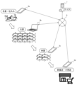
- FIG. 1 is a diagram showing the overall configuration of a system according to an embodiment of the present invention.
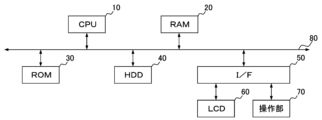
- 1 is a diagram showing a hardware configuration of information equipment included in a system according to an embodiment of the present invention.
- FIG. 2 is a block diagram showing the functional configuration of a service server according to an embodiment of the present invention.
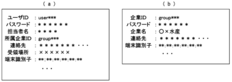
- FIG. 3 is a diagram showing an example of user information and company information according to an embodiment of the present invention. It is a figure showing an example of transaction information concerning an embodiment of the present invention.
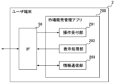
- FIG. 2 is a block diagram showing the functional configuration of a user terminal according to an embodiment of the present invention. It is a sequence diagram showing information registration operation in a system according to an embodiment of the present invention.
- FIG. 3 is a diagram showing an example of an information registration screen according to an embodiment of the present invention.
- FIG. 7 is a flowchart illustrating an operation of generating a product name option list according to an embodiment of the present invention.
- FIG. 3 is a diagram showing a manner of extracting information when generating a product name option list according to an embodiment of the present invention.
- FIG. 3 is a diagram illustrating options for product names on the information registration screen according to the embodiment of the present invention. It is a diagram showing the relationship of information with a parent transaction when transaction information according to an embodiment of the present invention is newly registered.
- FIG. 6 is a diagram showing an example of registration information when a plurality of records are registered according to an embodiment of the present invention. It is a figure showing an example of a sale data list display screen concerning an embodiment of the present invention.
- FIG. 1 It is a figure showing an example of a purchase data list display screen concerning an embodiment of the present invention. It is a figure showing an example of a transaction list display screen concerning an embodiment of the present invention. It is a flowchart showing the generation operation of the transaction list display screen according to the embodiment of the present invention. It is a figure showing an example of a purchase data list display screen concerning an embodiment of the present invention. It is a figure showing an example of a transaction list display screen concerning an embodiment of the present invention. It is a figure showing an example of a purchase amount post-designation screen concerning an embodiment of the present invention. It is a figure showing an example of a transaction list display screen concerning an embodiment of the present invention. FIG.
- FIG. 6 is a diagram illustrating rules for the display format of buying amounts and selling amounts on a transaction list display screen according to an embodiment of the present invention. It is a figure showing an example of average yield rate information concerning an embodiment of the present invention. It is a figure showing an example of a yield rate time series display screen concerning an embodiment of the present invention.
- 3 is a flowchart showing a product list generation operation according to an embodiment of the present invention. It is a diagram showing an overview of a store entry management function according to an embodiment of the present invention.
- FIG. 2 is a block diagram showing the functional configuration of a user terminal according to an embodiment of the present invention.
- FIG. 3 is a diagram showing an example of user information and company information according to an embodiment of the present invention.
- FIG. 3 is a diagram showing an example of store entry information according to an embodiment of the present invention.
- FIG. 3 is a sequence diagram showing store entry management operations according to an embodiment of the present invention.
- 12 is a flowchart illustrating an operation for generating an option list in a buyer column according to an embodiment of the present invention.
- FIG. 7 is a diagram illustrating the execution results of a query for generating an option list for a buyer column according to an embodiment of the present invention. It is a figure which shows the example of a display of the options of a buyer column based on embodiment of this invention. It is a figure showing an example of transaction information concerning an embodiment of the present invention.
- FIG. 2 is a sequence diagram illustrating an order processing operation according to an embodiment of the present invention.
- FIG. 3 is a diagram showing the relationship between transaction information of an order source and transaction information of an order source when transaction information that is order information according to an embodiment of the present invention is registered. It is a figure showing an example of an inventory allocation screen concerning an embodiment of the present invention. FIG. 3 is a diagram illustrating an example of inventory allocation information according to an embodiment of the present invention.
- Embodiment 1 Embodiments of the present invention will be described below with reference to the drawings.
- a market transaction management system that manages product purchase and sale information in a fresh food trading market will be described.
- this embodiment provides a function that allows the flow of transactions to be grasped after the fact. This is the gist of the matter.
- FIG. 1 is a diagram showing the overall configuration of a system according to this embodiment.
- the market trading management system includes a service server 1 that provides services in the system, and a plurality of user terminals 2a to 2d (hereinafter generally referred to as (referred to as "user terminal 2").
- users who use this system are traders who buy and sell products in the wholesale market. These include businesses, restaurants, and retail stores.
- This format is a typical format in the wholesale market, and there are cases where a transporter is placed between each of the traders shown in FIG. 1, and where each trader is divided into multiple levels.
- the service server 1 and user terminals 2a to 2d are connected to a network A such as the Internet, and can communicate with each other.
- the service server 1 is a server managed by the operating entity of this system, and has the function of providing a GUI (Graphical User Interface) when using this system from the user terminal 2, and the buying and selling information input on each user terminal 2. Provides a function to accept and record.
- the user terminal 2 is an information processing terminal such as a smartphone, tablet, notebook PC, or desktop PC, and is an electronic device used by a user who uses this system.
- FIG. 2 is a diagram showing the hardware configuration of information devices such as the service server 1 and the user terminal 2 included in the system according to the present embodiment.
- the system according to this embodiment can be realized by the hardware configuration of general information processing equipment, and as shown in FIG.
- a hard disk drive (HDD) 40 and an I/F 50 are connected via a bus 80.
- an LCD (Liquid Crystal Display) 60 and an operation unit 70 are connected to the I/F 50.
- the CPU 10 is a calculation means and controls the operation of the entire information device.
- the RAM 20 is a volatile storage medium in which information can be read and written at high speed, and is used as a work area when the CPU 10 processes information.
- the ROM 30 is a read-only nonvolatile storage medium, and stores programs such as firmware.
- the HDD 40 is a nonvolatile storage medium in which information can be read and written, and stores an OS (Operating System), various control programs, application programs, and the like.
- the I/F 50 connects and controls the bus 80 and various hardware, networks, and the like.
- LCD 60 is the visual user interface.
- the operation unit 70 is a user interface such as a keyboard, a mouse, various hard buttons, a touch panel, etc. through which the user inputs information to the information device. Note that since the service server 1 is operated as a server, user interfaces such as the LCD 60 and the operation unit 70 can be omitted.
- the service server 1 includes a request processing section 101, a vendor information processing section 102, a vendor information storage section 103, a transaction information processing section 104, and a transaction information storage section 105.
- a software program for realizing the functional configuration shown in FIG. 3 is used as a market transaction management program.
- the request processing unit 101 performs various processes in response to requests from applications running on the user terminal 2 and responds to the requests.
- the vendor information processing section 102 performs processing such as registering information in the vendor information storage section 103 and searching and extracting information under the control of the request processing section 101.
- the vendor information storage unit 103 stores information on vendor companies that are users of this system and information on their personnel.
- the transaction information processing unit 104 performs processing such as registering information in the transaction information storage unit 105 and searching and extracting information under the control of the request processing unit 101.
- the transaction information storage unit 105 stores information indicating the relationship between each transaction, in addition to the content and subject of the transaction conducted by the user of this system.
- FIGS. 4(a) and 4(b) are diagrams showing the contents of one record of information stored in the vendor information storage unit 103, where FIG. 4(a) is user information and FIG. Information is shown respectively.
- the user information includes information such as "user ID”, “password”, “person in charge”, “company ID”, “contact information”, and "receipt location”. include.
- “User ID” is a user identifier that identifies a user who uses this system.
- Password is authentication information for the user to log into this system.
- "Person in charge name” is character information indicating the name of the user who uses this system.
- "Affiliated company ID” is an identifier indicating the company to which the user belongs, but is left blank in the case of a user who uses the system as an individual.
- Contact is the contact information of the user of this system, such as address, telephone number, email address, etc.
- "Receiving location” is information that indicates where the user will deliver the item in the market when he or she buys it. For example, the user's assigned pickup location in the market or the location of the delivery vehicle. This is a parking place.
- the company information includes information of "company ID”, "password”, "company name”, and "contact information”.
- “Company ID” is an identifier for identifying a user who uses this system, and corresponds to "affiliated company ID” in FIG. 4(a).
- the "password” is authentication information for logging into this system using the "company ID” of the record.
- "Company name” is character information indicating the name and trade name of the company of the record.
- Contact information is contact information for the company, such as address, phone number, and email address. Note that a "receipt location" may be specified for company information as well as for user information.
- FIG. 5 is a diagram showing the contents of one record of transaction information stored in the transaction information storage unit 105.
- the transaction information storage unit includes "transaction ID”, “buyer ID”, “seller ID”, “person in charge name”, “product code”, “product name”, “ Information on “Standards”, “Country of Origin”, “Quantity”, “Weight”, “Unit Price”, “Consumption Tax Rate”, “Transaction Date and Time”, “Parent Transaction ID”, “Receipt Confirmation”, “Remarks” and “Sold Out” including.
- Transaction ID is a transaction identifier that identifies each transaction information record.
- the "buyer ID” is a buyer identifier that identifies the trader who sold the product in the transaction, and corresponds to the "user ID” in FIG. 4.
- the “seller ID” is a seller identifier that identifies the merchant who purchased the product in the transaction, and corresponds to the "user ID” in FIG. 4.
- the "person in charge name” is the name of the person in charge of the vendor who purchased the product in the transaction.
- a “product code” is a code number given to a product bought or sold in a transaction, and is used to identify fish of the same species but with different specifications.
- Product name is the name of the product bought and sold in the transaction.
- Standard is information that indicates the standard of the product bought and sold in the transaction. For example, for fish such as sardines, it is indicated by the weight per predetermined number of fish, such as "**kg/**fish". . In addition, in the case of tuna, it is a number that indicates the part such as “No. 1" to “No. 4", and in the case of shrimp, it is a number that indicates the part of the body, such as "16-20", “21-25", “26-30”, etc. It is indicated by the number of tails.
- Oil is information indicating the origin of the product bought and sold in the transaction.
- Quantity is information indicating the number of products (number of items) bought and sold in the transaction.
- Weight is information indicating the weight of the product bought and sold in the transaction.
- Unit price is information indicating the price per predetermined weight of the product bought and sold in the transaction.
- Consption tax rate is information indicating the consumption tax rate applied to the transaction. Information such as “product name”, “standard”, “place of origin”, “quantity”, “weight”, and “unit price” is used as information on transaction details.
- Transaction date and time is information indicating the date and time when the transaction was performed.
- the "parent transaction ID” is a parent transaction identifier indicating a purchasing transaction of the product bought and sold in the transaction, that is, the parent transaction, and corresponds to the "transaction ID.”
- “Receipt confirmation” is check information indicating whether or not the goods purchased and sold in the transaction have been received and confirmed at the buyer's receiving location.
- "Remarks” is character information that can be freely input during transactions.
- “Sale Ended” is check information indicating that the sale of the product purchased through the transaction has ended.
- the market sales management application 200 is configured by reading software programs for configuring the market sales management application 200 into the RAM 20, and having the CPU 10 perform calculations according to those programs.
- the market sales management application 200 according to this embodiment is a web application. That is, when the user terminal 2 accesses the service server 1 via the web browser installed on the user terminal 2, a program for configuring the market sales management application 200 is downloaded to the user terminal 2 as website information. , the market sales management application 200 is configured on the user terminal 2 according to the program.
- the market sales management application 200 includes an operation reception section 201, a display processing section 202, and an information communication section 203.
- the operation reception unit 201 receives a user's operation on the operation unit 70 of the user terminal 2 via the I/F 50.
- the display processing unit 202 controls the display of the GUI of the market sales management application 200 based on the user's operation details acquired by the operation reception unit 201 and the information acquired from the service server 1.
- the information communication unit 203 exchanges information with the service server 1 according to the operating state of the market sales management application 200.
- FIG. 7 is a sequence diagram showing the operation of newly registering transaction information in this system.
- the seller's user terminal 2a accesses the service server 1 via the web browser function, and the GUI of the market sales management application 200 is displayed on the LCD 60 (S701).
- login processing is performed by authentication using a user identifier such as an e-mail address included in the "user ID" or "contact” information and a "password.”
- the operation reception unit 201 receives the operation contents of the operation unit 70 by the user, the information communication unit 203 acquires information from the service server 1 in response to the operation, and the display processing unit 202 uses the market sales management application 200 based on the information.
- the GUI By controlling the GUI, a transaction information registration screen is displayed.
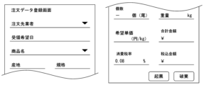
- FIGS. 8A and 8B are diagrams showing a screen for registering sell data (hereinafter referred to as a "sell data registration screen") of the GUI of the market sales management application 200.
- the selling data registration screen in this system includes input fields for inputting each piece of information explained in FIG. 5.
- the sales data registration screen in this system includes a function to assist in inputting information in each input field.
- the screens shown in FIGS. 8(a) and 8(b) are used as information input screens for accepting input of information to be stored in the transaction information storage unit 105.
- the input field displayed as "Company” in FIG. 8(a) is an input field for specifying the trader who will purchase the product in the transaction.
- this input field in addition to free input, it is also possible to select from displayed options, and the "company name" of the record stored in the vendor information storage unit 103 of the service server 1 is displayed as an option.
- Each company name option is associated with a "user ID” shown in Figure 4, and when a company name is selected, the "user ID" associated with it is automatically selected as information to be input. .
- the input field displayed as "product name” in FIG. 8(a) is an input field for specifying the product to be bought and sold in the transaction.
- This input field is also selective, and the product names of products that the seller has already purchased are displayed as options. This function to display product name options will be explained.
- a list generated based on the "product name” of the transaction information stored in the transaction information storage unit 105 is used. This list is generated in the screen information generation process in S701 of FIG. With reference to FIG. 9, details of the screen information generation process in S701 of FIG. 7 will be described.
- the request processing unit 101 of the service server 1 first receives an authentication request including a user ID and password from the user terminal 2 requesting screen display (S901). Then, the vendor information processing unit 102 refers to the vendor information storage unit 103 based on the received user ID and password, confirms that the user ID and password match, and performs authentication processing (S902).
- the request processing unit 101 notifies the user terminal 2 that made the authentication request of the error (S906) and ends the process.
- FIG. 10 is a diagram conceptually showing the process of extracting information using the "buyer ID” as a key in the transaction information storage unit 105.
- “product code”, “product name”, and “standard” are "***, sardine, **kg/** tail", "***, tuna, No. 1", and " ***, shrimp, 16-20'' is extracted.
- the request processing unit 101 extracts the information of "transaction ID”, “product code”, “product name”, “production area”, and “standard” from the extracted records, A list is generated for the "product name” options shown in FIG. 8(a) (S904). Then, the request processing unit 101 transmits the GUI information of the market sales management application 200 on the user terminal 2 and the list information generated in S904 to the user terminal 2 as a response to the authentication request (S905), and ends the process. . That is, here, the request processing unit 101 functions as an input screen information providing unit that provides information for displaying the screens shown in FIGS. 8(a) and 8(b).
- FIG. 11 is a diagram showing a display mode of options in the input column for "product name” shown in FIG. 8(a). As shown in FIG. 11, the list generated by the process of FIG. 9 is displayed as options.
- the login process and the process of generating the option list for the "Product Name" input field have been described as a series of processes, but the process between S902 and S903 is not necessarily continuous, and there may be a time lag.
- the user terminal 2 performs an operation to display the sales data registration screen with the login operation already performed, and the user terminal 2 requests the service server 1 for screen information.
- the service server 1 executes the processes from S903 onwards.
- the operation reception unit 201 receives the operation content, and the display processing unit 202 processes the selected information to display the "product name", "product name”, etc. shown in FIG. "Country of origin” and "Standard" are automatically entered.
- the display processing unit 202 processes the selected information to display the "product name", "product name”, etc. shown in FIG. "Country of origin” and "Standard" are automatically entered.
- FIG. 8(a) and FIG. 11 an example was explained in which the information of "Product Name", “Production Area”, and “Standard” are selected all at once in the input field of "Product Name”. , it is also possible to make individual selections in each input field, and options can be generated by the same process as above.
- buttons for "add” or “delete” a "unit” are displayed on the selling data registration screen.
- buttons for “Add” or “delete” a "unit” are displayed on the selling data registration screen.
- input fields for "Quantity” and “Weight” are added as shown in Figure 8(b), and multiple "Quantity” and “Weight” input fields are added. It becomes possible to input.
- the information transmitted in S702 includes the information input on the screen shown in FIG. 8(a) as described above, but the information included by selecting the "Product Name” column is the "Product Code” shown in FIG. ",” and “product name,” as well as “transaction ID” information as shown in FIG. 10. It also includes the user ID authenticated in the login process of S701, that is, the logged-in user ID.
- the request processing section 101 receives the information, the transaction information processing section 104 registers the information in the transaction information storage section 105 under the control of the request processing section 101, and processes the request.
- the unit 101 performs response processing for the user terminal 2 (S703).
- the login-authenticated user ID is registered as the "seller ID.” That is, here, the transaction information processing section 104 functions as a transaction information storage processing section.
- FIG. 12 is a diagram showing the relationship between the record newly registered in the process of S703 and the record corresponding to the parent transaction.
- the "transaction ID” in the record of the parent transaction is registered as the “parent transaction ID” of the newly registered record.
- the "buyer ID” in the parent transaction record is the same as the “seller ID” in the newly registered record.
- the "product code”, "product name”, and "place of origin” will also be the same.
- the “standards” are basically the same, the information on the standards may differ between the time of purchase and the time of sale, such as when purchasing items are cut up and sold.
- the user ID is the "seller ID” and the date information of the "transaction date and time” is included.
- a screen showing a list of selling data registered on that day is displayed as a processing result screen indicating that information registration has been completed (S704).
- FIG. 14 is a diagram showing an example of the sell data list screen displayed in the process of S704.
- FIG. 14 on the selling data list screen, among the information included in each record, "product", “production area”, “quantity”, “weight”, “unit price”, “location”, “Delivery status” information is displayed together for each company name corresponding to each buyer ID.
- the "location” information is the “receiving location” information explained in FIG. 4.
- FIG. 15 is a diagram showing an example of the purchase data list screen displayed in S705.
- the service server 1 selects the user ID notified along with the request from among the data stored in the transaction information storage unit 105.
- a list is sent to the user terminal 2, in which records are extracted that have the "buyer ID” and the date information of the "transaction date and time” is the current day.
- a screen showing a list of buying data registered on that day is displayed as shown in FIG. 14.
- the "Delivery status" item is a GUI that allows the user to add a check. For example, a user who makes purchases in an actual market purchases necessary products at various locations and stores. The products are then delivered from each store to a designated collection point and loaded into a vehicle. At that time, by checking the "Delivery status" item on the purchase data list display screen shown in Figures 14 and 15, you can check whether all sold products have been delivered or all purchased products have been delivered. can.
- the user terminal 2 informs the service server 1 that the "Delivery Status" column has been checked.
- a "transaction ID” indicating the target record is notified.
- the information is passed from the request processing unit 101 to the transaction information processing unit 104, and the transaction information processing unit 104 extracts the record of the notified “transaction ID” and Update the "Status" check information.
- the seller of the item may operate the item on the sales data list display screen explained in Figure 14 to check it, or both the seller and the buyer of the item may check the item. It may also be checked. This makes it possible to check whether the seller has delivered the product and whether the buyer has received the product.
- the "Delivery status" item is shown as check data, but if the data is to be checked by both the buyer and seller as described above, it may be written as two-digit binary data, for example. , can be realized as one item by setting the state checked by the buyer as "10", the state checked by the seller as "01”, and the state checked by both parties as "11".
- FIG. 16 is a diagram showing an example of a transaction list screen among the screens that are possible using the "parent transaction ID" in this system.
- the transaction list screen in this system On the transaction list screen in this system, the purchase amount and sales amount of the products purchased by each user are compared and displayed. That is, the transaction list screen shown in FIG. 16 is used as the transaction amount display screen.
- each user can prevent the purchase of products from being sold out or from erroneously concluding a transaction for more than the amount in stock.
- FIG. 17 is a flowchart showing the operation of the service server 1 that receives a request for a transaction list display screen from the user terminal 2.
- the user terminal 2 of the requesting user notifies the service server 1 of the user ID along with a request to display the transaction list display screen.
- the information is passed from the request processing unit 101 to the transaction information processing unit 104, and the transaction information processing unit 104 Information is extracted from the transaction information storage unit 105 based on the ID" (S1701).
- the transaction information processing unit 104 selects data in which the “buyer ID” is the notified “user ID” and the “transaction date and time” is the current day among the data stored in the transaction information storage unit 105. Extract.
- the data extracted in S1701 is data on transactions in which the user purchased products on that day, that is, purchase transaction data, and the process in S1701 is a process for extracting the amount of products purchased.
- the transaction information processing unit 104 After extracting the information in this way, the transaction information processing unit 104 selects each piece of extracted data in order and performs processing to generate a comparison screen as shown in FIG. 15 (hereinafter referred to as "comparison information generation processing"). ) repeatedly. Therefore, as a process for determining repetition, the transaction information processing unit 104 checks whether there is any remaining data that has not been selected as a target for comparison information generation processing among the extracted data (S1702).
- the transaction information processing unit 104 selects one of the unselected data and refers to its "transaction ID" (S1703). Then, the transaction information processing unit 104 extracts a record whose “parent transaction ID” is the “transaction ID” referenced in S1703 from among the data stored in the transaction information storage unit 105 (S1704).
- the data extracted in S1704 is data on the sale of the purchased product in the transaction indicated by the "transaction ID” referenced in S1703, that is, sales transaction data, and the process in S1704 is a process for extracting the sales amount of the product. be.
- the transaction information processing unit 104 that has extracted the sales transaction data for the selected purchase transaction refers to the "weight” and “unit price” of the extracted sales transaction data, totals the "weight”, and adds the "unit price” to the "weight”.
- the multiplied sales amount is totaled (S1705). As a result, the total amount and total sales amount of the selected purchased product are calculated.
- the transaction information processing unit 104 displays the information displayed on the transaction list display screen as shown in FIG. Information such as “sales amount (yen),” “sales amount (kg),” and “sales end” is extracted and stored (S1706).
- the transaction information processing unit 104 repeats the processes of S1703 to S1706 until there are no records extracted by the process of S1701 (S1702/YES), and when there are no unselected records (S1702/NO), the records are stored by the process of S1706. Based on the information obtained, screen information for displaying the transaction list display screen shown in FIG. 16 is generated and transmitted to the requesting user terminal 2 (S1707), and the process ends. In this way, the transaction information processing section 104 functions as a transaction amount display screen generation section.
- FIG. 16 A screen as shown in FIG. 16 is displayed on the user terminal 2.
- a display like the one shown in FIG. 16 makes it possible to objectively check the purchase amount and sales amount.
- the "sold out” item is a GUI that allows the user to add a check mark.
- the user terminal 2 sends a request to the service server 1 to update the "Sales Ended” check status by checking the "Transaction ID” of the target record. " (transaction ID selected in S1703).
- the transaction information processing unit 104 extracts a record from the transaction information storage unit 105 based on the notified “transaction ID” and checks whether the extracted record is “sold out”. Update.
- the vendor who sells the product inputs information about the product to be sold on the screens shown in FIGS. 8(a) and 8(b).
- the "unit price” information is entered blank.
- the "unit price” is displayed as undetermined, and as shown with diagonal lines in the figure, the transaction is not being accepted by the seller. The transaction is highlighted so that it can be objectively understood that the transaction is based on a sales request.
- FIG. 19 is a diagram showing an example of a transaction list display screen when products for sales request transactions are displayed. As shown in FIG. 19, on the transaction list display screen that includes the products of the sales request transaction, the products of the sales request transaction are highlighted in the same way as in FIG.
- the highlighted display as shown in FIGS. 18 and 19 is realized by the transaction information processing unit 104 that generates display information in the service server 1 in response to a request from the user terminal 2.
- the transaction information processing unit 104 When the transaction information processing unit 104 generates display information for the purchase data list display screen or the transaction list display screen, the record related to the sales request transaction, that is, the record in which the purchase amount is blank, is highlighted.
- Generate display information Such a display can be realized, for example, by setting a style sheet of a web source that configures the screen.
- the buying side and the selling side discuss the sales amount (the "unit price” on the record) that is blank, and enter the information after the fact to clear the undetermined state.
- the transaction needs to be completed.
- a screen hereinafter referred to as " ⁇ Purchase amount post-specification screen'' will be displayed.
- the request processing unit 101 receives the request, and the transaction information processing unit 104 searches the target record stored in the transaction information storage unit 105 based on the information included in the request. Update. Through such processing, the sales request transaction is completed.
- each transaction is recorded as one record in a market transaction in which a product is circulated between multiple traders from upstream to downstream.
- a "parent transaction ID" which is information indicating a transaction one upstream of the product to be traded, that is, a transaction related to the purchase of that product, is recorded.
- the functions of this system include the function of issuing invoices and statements of delivery.
- Such functionality can be implemented based on information stored in the system as shown in FIG. For example, if you want to issue an invoice by aggregating transactions by month, create a record where the "buyer ID" matches the billing company and the year and month of "transaction date and time” matches the billing month. It is possible to easily generate a bill by extracting the information.
- the operation reception unit 201 on the user terminal 2 After receiving the operation details, the information communication unit 203 transmits a bill generation request to the service server 1.
- the request processing section 101 receives the request and passes the information to the transaction information processing section 104.
- the transaction information processing section 104 which has received the information from the request processing section 101, extracts the information stored in the transaction information storage section 105 based on the specified information, performs aggregation and listing, and displays the invoice. Generate display information for When the transaction information processing unit 104 generates bill display information, the request processing unit 101 transmits the information to the user terminal 2 that made the request. As a result, the invoice is displayed on the user terminal 2, and can be sent to the billing company based on the buyer ID or output as paper by printing it out.
- records are extracted for the user IDs of all users belonging to that company.
- the user IDs of all users belonging to that company For example, in S1701 of FIG. 17, in addition to a record whose "buyer ID" is the "company ID” of the logged-in company, in addition to the record whose "company ID” of the user information explained in FIG. 4(a) is "the logged-in company ID”. All "user IDs” of records that match the "company ID” are acquired, and records where all the acquired "user IDs” match the "buyer ID” are also extracted. This allows a user who logs in with a company ID to understand the transactions of all users belonging to that company. The function of referring to the transaction information of the affiliated user by logging in with the company ID is the same in the subsequent embodiments as well.
- Embodiment 2 functions implemented on the transaction list display screen described with reference to FIG. 16 will be explained in consideration of the actual situation at the site.
- a purchase amount (kg) and a sale amount (kg) can be displayed in a comparative manner.
- a list of transactions will be displayed when the purchased items are sold out.
- the "buying amount (kg)” and “selling amount (kg)” displayed on the screen should match.
- FIG. 21 is a diagram showing an example of a transaction list display screen according to the present embodiment.
- the display unit of "sales volume” is in a format that corresponds to the sales format of each product, and the yield rate calculated in that transaction for each product and the yield rate of the product as a whole are shown.
- the "yield rate/average” item is displayed to compare and display the average value of the yield rate.
- Information for displaying the screen shown in FIG. 21 is generated by the transaction information processing unit 104 similarly to FIG. 16. That is, the transaction information processing section 104 functions as a yield rate calculation section.
- the "quantity” may not be recorded at the time of purchase.
- shrimp are traded by weight in purchasing transactions, and the number of shrimp per predetermined weight is stored as a "standard”. Therefore, in the example of FIG. 21, the expected number of fish to be purchased calculated from the "standard” information and the "weight” information is displayed as "40 (fish)".
- the "sales amount” is “6 (kg) + 38 (tails)"
- the "weight” and “number” are aggregated and displayed.
- the records extracted in S1704 of FIG. 17 include records in which "weight” is blank and records in which it is not.
- both "quantity” and “weight” are selected as the “purchasing quantity” to be compared, and if "quantity” is blank, the expected quantity may be calculated from “standard” and "weight”. The same is true.
- FIG. 22 is a diagram showing the display format rules for each product as shown in FIG. 21.
- the rules shown in FIG. 22 are stored in the transaction information processing unit 104. Such display selection for each product is executed in S1705 of the process described in FIG. 17.
- the transaction information processing unit 104 that extracted the sales data in S1704 selects the display format of "buying amount” and "selling amount” on the transaction list display screen according to the rules shown in FIG.
- the transaction information processing unit 104 calculates the yield rate in S1705.
- the amount is simply calculated by dividing the "selling amount” by the “buying amount.”
- the transaction information processing unit 104 calculates the respective yield rates and adds them up.
- the transaction information storage unit 105 stores average yield rate information (hereinafter referred to as "average yield rate information") for each product and each standard.
- FIG. 23 is a diagram illustrating an example of average yield rate information according to this embodiment. As shown in FIG. 23, the average yield rate information according to this embodiment includes information on "product", “standard”, “average yield rate”, and "number of samples”. That is, here, the transaction information storage section 105 functions as an average yield rate storage section.
- the "average yield rate” is information indicating the average value of the yield rates calculated in the system so far. This allows the average value of the yield rate of products traded via this system to be grasped. Further, the "number of samples” is a value indicating the number of data used to calculate the "average yield rate” at that point.
- the transaction information processing unit 104 extracts a record that matches the "product" and "standard” of the record being processed, that is, the record selected in S1703, from the average yield rate information, and " to get. Then, in S1706, information for displaying the contents as shown in FIG. 21 is stored. Through such processing, screen information for displaying a transaction list display screen as shown in FIG. 21 is generated.
- the user who has sold all of the respective products operates the check box for "Sales Ended” on the screen shown in FIG. 21. Then, the yield rate information is updated along with the update of "Sales Ended" in the transaction information storage unit 105 described in the first embodiment.
- the transaction information processing unit 104 performs an update process for the yield rate information in addition to the above-described "sales end" check update process.
- the transaction information processing unit 104 first extracts the record of the notified "transaction ID" from the transaction information storage unit 105, and stores it in association with the notified yield rate. Therefore, the transaction information storage unit 105 according to the present embodiment includes yield rate information in addition to the information shown in FIG.
- the transaction information processing unit 104 performs the process of updating the average yield rate information shown in FIG. 23.
- the transaction information processing unit 104 acquires the "product" and "standard” from the record of the notified "transaction ID”, and selects records that match each other as the average yield rate information shown in FIG. 23. Extract from. Then, assuming the "number of samples" of the extracted records as n, the updated yield rate is calculated using the following equation (1), and the "average yield rate" is updated, and the "number of samples” is incremented.
- the yield rate of each transaction information stored in the transaction information storage unit 105 and the information on the average yield rate shown in FIG. 23 are updated.
- the user can compare and check the yield rate of each product and the average yield rate using a screen as shown in FIG. 21.
- FIG. 24 is a diagram showing an example of a yield rate time-series display screen (hereinafter referred to as a "yield rate time-series display screen") according to the present embodiment.
- a line graph with the vertical axis as the yield rate (%) and the horizontal axis as the transaction date and time shows the results that match a specific combination of "product" and "standard”.
- the "yield rate” of records is displayed in chronological order. Further, as shown in FIG. 23, the stored average yield rate is displayed as a broken line.
- the screen shown in FIG. 24 is displayed on the user terminal 2 based on screen display information generated by the service server 1.
- the service server 1 generates screen display information for displaying the screen shown in FIG. 24 in response to a request from the user terminal 2.
- the request from the user terminal 2 to the service server 1 includes information indicating that it is a request to generate display information for the yield rate time series display screen shown in FIG. 24, as well as the "user ID" of the requester, the user. Contains information such as "product name” and "standard”. That is, when requesting display information on the yield rate time series display screen, the user specifies at least "product name” and "standard” and performs the request operation.
- the transaction information processing unit 104 creates a record in which the notified "user ID” matches the "buyer ID” and the notified "product name” and “standard” match. is extracted from the transaction information storage unit 105.
- the transaction information processing unit 104 refers to the "transaction date and time” and "yield rate” of the records thus extracted, and generates information for displaying a graph as shown in FIG. 24.
- the transaction information processing unit 104 refers to the average yield rate information based on the notified "product” and “standard”, extracts matching records, and extracts the "average yield rate” of the corresponding "product” and “standard”. Get “rate”. As a result, information for displaying the broken line shown in FIG. 24 is generated.
- the screen shown in FIG. 24 allows the user to grasp the "yield rate" of the products purchased by the user in chronological order for each "product" and "standard.”
- the yield rate decreases around timing t1 .
- the buying amount and selling amount are compared on the transaction list display screen. It becomes possible to display.
- Embodiment 3 a real-time information reflection function of the product list on the sales data registration screen described in FIGS. 9 to 11 and an additional function related to registration of transaction information in FIGS. 8(a) and 8(b) will be described.
- the products displayed in front of the store are sold and the products are handed over once the sale is completed, so the products are reliably delivered to the buyers.
- the sales contract is made first, and the product is sometimes delivered afterwards. Therefore, immediately after a transaction is concluded, there will be products left on site, and unless the products are reliably reserved for each sales contract, there is a possibility that more products will be sold than the amount purchased.
- FIG. 25 is a flowchart showing details of the process of S904 in FIG.
- Embodiment 1 the case where information is extracted from all the records extracted by the process of S903 and a list is generated in S904 has been described as an example.
- records to be included in the list are selected from among the records extracted in the process of S903.
- the transaction information processing unit 104 performs processing by sequentially referring to the records extracted in S903. Therefore, first, it is checked whether any unselected data remains among the extracted data (S2501). If there is still unselected data (S2501/YES), the transaction information processing unit 104 selects one of the unselected data (S2502), and checks whether "sale ended" has been checked (S2503). ).
- the transaction information processing unit 104 excludes the selected record from the list (S2504), and repeats the process in S2501.
- the transaction information processing unit 104 refers to the "transaction ID" of the selected record and enters the data stored in the transaction information storage unit 105. Among them, records with matching "parent transaction ID” are extracted (S2505).
- the record extracted in S2505 is a record indicating a transaction in which a product purchased through the transaction of the record selected in S2502 was sold.
- the transaction information processing unit 104 totalizes the sales amount by referring to the "number” and "weight” of the extracted records (S2506).
- the process of S2506 is basically a process of summing up "weight”, but as explained in the second embodiment, "weight" information may not be input in a sales transaction. Therefore, in S2506, the transaction information processing unit 104 appropriately selects a sales amount aggregation method according to the rules as explained in FIG. 22.
- the transaction information processing unit 104 that has aggregated the sales amount checks the purchase amount based on the record selected in S2502, and compares it with the aggregation result in S2506 (S2507).
- the transaction information processing unit 104 basically refers to the "weight”, but may refer to the "number” depending on the tally result in S2507, or may refer to the "quantity" calculated from the "standard” and "weight”. Use the expected number of pieces.
- the transaction information processing unit 104 displays only records other than those excluded from the list, that is, records that are determined to be still in stock.
- a product list is generated as in S904 of 9 (S2508), and the process ends. Through this process, the selection list of products shown in Figures 8(a) and (b) is generated in a timely manner according to the sales status of purchased products, and products that have already been sold out are not erroneously traded. You can prevent this from happening.
- the product list information includes information such as "transaction ID”, “product code”, “product name”, “place of origin”, and "standard”.
- the system further includes the above-mentioned “inventory amount information”.
- “inventory information” associated with the product name is referenced and compared with the information input in "weight.”
- Embodiment 4 a function for assisting input in the "buyer" field on the sell data registration screen shown in FIGS. 8(a) and 8(b) will be described.
- One of the features of this system is that buyers and sellers are identified by IDs in recording transaction information, as explained in FIG. 12 and the like. Therefore, when registering information on the sales data registration screen shown in FIGS. 8(a) and 8(b), it is necessary to accurately specify the user who is purchasing the product using the "buyer" column.
- the input in the "buyer” field prohibits the user from freely inputting information, and the information has already been registered in the user information and company information in the vendor information storage unit 103 of the service server 1, as shown in FIGS. 4(a) and (b). It is preferable to use a multiple-choice format with the information listed as options. However, as the number of registered user information and company information increases, the number of options also increases. When there are a huge number of options, it is inconvenient for the user to have to search for a buyer from among the huge number of options.
- the present embodiment addresses such problems by detecting when a buyer visits the store of each trader conducting transactions in the market, and when each store registers transaction information as a seller.
- the system assists the selection of "buyers” by preferentially displaying users whose visits to the store are detected as options for "buyers.”
- FIG. 26 is a diagram showing the store visit detection function according to this embodiment.
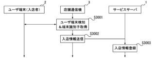
- a store communication device 3 is installed in each store to detect the terminal of a user who is a buyer. That is, the store communication device 3 functions as a store entry recognition section.
- the store communication device 3 according to the present embodiment is a small information processing terminal having a Bluetooth function and a network communication function, and has a hardware configuration similar to the configuration described in FIG. 2. Furthermore, by installing software on the user terminal 2 used by a user at the store, the user terminal 2 can be made to function as the store communication device 3.
- the user terminal 2 of the user visiting the store has the same configuration as the embodiment described above except that it has a short-range communication antenna 90 as shown in FIG. communicate.
- the store communication device 3 recognizes that the user terminal 2 has entered the store through short-range communication with the user terminal 2 using the Bluetooth function, and transmits store entry information to the service server 1 via the network A.
- FIGS. 28(a) and 28(b) are diagrams showing examples of user information and company information stored in the vendor information storage unit 103 of the service server 1 according to the present embodiment.
- the user information and company information according to this embodiment include information on "terminal identifier" in addition to the contents explained in FIGS. 4(a) and 4(b). include.
- This "terminal identifier" is information that can uniquely identify the user terminal 2 and is information that the store communication device 3 can acquire from the user terminal 2 via Bluetooth communication, and is typically a MAC (Media Access Control) address is used.
- MAC Media Access Control
- the vendor information processing unit 102 registers the information in the vendor information storage unit 103, and in the process of exchanging the information, by acquiring the MAC address of the terminal used by the user, as shown in FIG. "terminal identifier" is registered.
- the vendor information processing unit 102 acquires the MAC address of the terminal used by the user and compares it with the "terminal identifier" associated with the logged-in user ID. do. As a result, if the two are different, the vendor information processing unit 102 stores the acquired MAC address as a "terminal identifier" in association with the user information or company information of the user who has additionally logged in. This makes it possible to identify the user based on the "terminal identifier" even if the user uses multiple terminals.
- terminal identifier can be associated with multiple different user IDs.
- FIGS. 29(a) and 29(b) are diagrams showing examples of store entry information according to the present embodiment
- FIG. 29(a) shows information transmitted by the store communication device 3 to the service server 1
- FIG. b) is a diagram showing the contents of one record of the entry information table stored in the vendor information storage unit 103 in the service server 1.
- FIG. 30 is a sequence diagram showing the store entry detection process according to this embodiment.
- terminal identifier Users shopping around in the market where this system has been introduced carry a user terminal 2 with the functions described in FIG. 27, and as described in FIGS. is registered in the vendor information storage unit 103 of the service server 1 as a "terminal identifier.”
- the store communication device 3 installed in each store included in the market constantly detects terminals using the Bluetooth function, and when the user terminal 2 enters the communication range, it detects the user terminal 2 via the Bluetooth function. At the same time, the MAC address of the user terminal 2 is acquired as a terminal identifier (S3001).
- pairing may be required between the store communication device 3 and the user terminal 2 in advance for the process of S3001.
- each user can pair the store communication device 3 with his or her own user terminal 2 at a store that he or she frequently uses, so that from the next time onwards, he or she can pair the store communication device 3 with his or her own user terminal 2 without having to perform any pairing operations.
- the process of S3001 is automatically executed by simply visiting a store with the .
- the store communication device 3 that has acquired the terminal identifier from the user terminal 2 sets the preset user ID or company ID of the store as the "store entry ID,” and the acquired terminal identifier as the "entering person identifier,” and stores the current information. It is sent to the service server 1 along with the time (S3002). This "store entry ID" is used as a store identifier. As a result, the information shown in FIG. 29(a) is transmitted to the service server 1.
- the service server 1 that has received the information shown in FIG. Search for "terminal identifier”. Then, the user ID of the user information extracted as a result of the search or the company ID of the company information is acquired as a "store entry ID”, and the user enters the store with the "store entry ID” and "store entry date and time” received in S3002. It is stored in the vendor information storage unit 103 as an information table (S3003). As a result, the information shown in FIG. 29(b) is recorded in the service server 1.
- the information shown in FIG. 29(b) makes it clear who entered the store ("store entry ID”), where ("store entry ID”), and when ("store entry date and time”). Based on such circumstances, the gist of the present embodiment is to adjust the option list in the "buyer" column when registering information on the selling data registration screen shown in FIGS. 8(a) and 8(b).
- the vendor information processing unit 102 is configured to input the seller's user ID and store entry screen. Generate a list of options for the "buyer" column based on the information table.
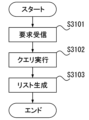
- FIG. 31 is a flowchart showing the processing.
- FIG. 31 shows a case where the user terminal 2 requests the service server 1 for screen information of the "selling data registration screen” in a state where the login process has already been performed.
- the request processing unit 101 in the service server 1 receives a request for screen information for the “selling data registration screen” from the user terminal 2 (S3101)
- the vendor information processing unit 102 sends a message to the vendor information storage unit 103 regarding the “buyer”
- a query is executed to generate a column option list (S3102).
- the query executed in S3102 first extracts the "user ID” and "person in charge” from the user information, extracts the “company ID” and “company name” from the company information, and extracts the "user ID” and "company ID” from the company information. ", "person in charge name” and "company name” are concatenated to create a table whose contents are "user name/company name” and “user ID/company ID” (hereinafter referred to as “user/company concatenation table”). generate.
- the "store entry ID" in the store entry information table is searched based on the user ID notified at the time of the request.
- a record whose "store entry ID” is the store that requested the "sales data registration screen” is extracted.
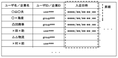
- the record of the user/company concatenation table whose "enterer ID” of the record extracted in this way matches the "user ID/company ID” it is associated with that "enterer ID”. Associate the date and time of entry. This results in a table configuration as shown in FIG. 32.
- the items are rearranged in descending order so that blank columns are placed later in the order for "date and time of store entry.”
- users/companies are sorted in the order in which they recently entered the store that requested the "sales data registration screen", and users/companies that do not have entry information are postponed.
- the vendor information processing unit 102 generates the execution result of such a query as an option list in the "buyer" column (S3103), and ends the process.
- the operation shown in FIG. 31 is a process executed when requesting screen information for the "sell data registration screen", and when generating the screen information for the "sell data registration screen", the process is performed as described in the first embodiment.
- the process in FIG. 9 is also executed.
- the "buyer” options on the "selling data registration screen” are sorted in the order of new arrivals to the target store, as shown in Figure 33. will be displayed. Therefore, users on the seller's side who register transaction information can easily select buyers who are in the store and are displayed with priority, without having to search for the target buyer from a huge number of registered users/companies. It becomes possible.
- the Bluetooth function is used as a mechanism for detecting entry into a store.
- This is a function that is naturally implemented in mobile terminals such as general smartphones, and is effective in that it can be easily realized and disseminated.
- Communication function may also be used. This is possible because the mechanism is not much different from the above, only the Bluetooth function is replaced with the NFC function.
- each store is presented with a sticker, signboard, etc. printed with an image code encoded with the store's ID and a URL (Uniform Resource Locator) that provides web access for notification of entry.
- a URL Uniform Resource Locator
- a user visiting the store reads the code with a camera mounted on his or her user terminal 2 to access the encoded URL on the web.
- This web access is a web access for notifying the service server 1 of entering the store (hereinafter referred to as "store entry notification web access"), and the user ID or company ID of each store is will be notified.
- the service server 1 that has received the store entry notification web access from the user terminal 2 returns a login screen to the user terminal 2 in order to request the user terminal 2 to log in.
- the user ID or company ID of the user who is the buyer is notified to the service server 1, and information as shown in FIG. 29(b) is recorded in the service server 1.
- this last login process will be omitted and the user ID or company ID that has already been logged in will be notified from the user terminal 2 to the service server 1. be able to.
- the image code may be presented by the user terminal 2 of the user who is the buyer, and read by a camera installed in a terminal installed at the store (hereinafter referred to as the "store entry management terminal"). It is possible to obtain similar effects.
- the user ID or company ID of the user is encoded in the image code presented by the user terminal 2 of the user who is the buyer.
- a user who enters a store uses the GUI function of this system to display on the screen a code in which his or her logged-in user ID or company ID is encoded.
- a function can be realized by the request processing unit 101 of the service server 1 generating screen information in response to a request from the user terminal 2 and sending it back to the user terminal 2.
- it can also be realized by the function of a program such as JavaScript that is downloaded and operated on the user terminal 2 side without communication with the service server 1.
- the store entry management terminal decodes the read code and sends the user ID or company ID obtained to the store registered in advance. This information is sent to the service server 1 along with the user ID or company ID of the store as store entry information. As a result, information as shown in FIG. 29(b) is recorded in the service server 1, and the same effect as described above can be obtained.
- Embodiment 5 In Embodiments 1 to 4, an example has been described in which a product to be sold is selected from among products whose purchase has already been confirmed at an upstream vendor, and transaction information is input. On the other hand, in the actual situation of transactions, there are cases in which a downstream vendor informs in advance of a transaction reservation or a desire to sell, that is, places an order for a product for which the upstream vendor has not yet confirmed its purchase.
- transaction information is not stored in the transaction information storage unit 105 for products whose purchase is not confirmed at the upstream vendor, so even if the order details are recorded as transaction information, the upstream vendor of the product It is not possible to specify the "parent transaction ID" that specifies the purchasing transaction. In this embodiment, such an aspect will be explained.
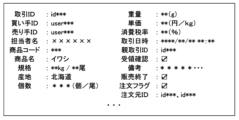
- FIG. 34 is a diagram showing the contents of one record of transaction information stored in the transaction information storage unit 105 according to the present embodiment.
- the transaction information according to this embodiment includes information on an "order flag” and an "order source ID” in addition to the content described in FIG.
- the "order flag” is an identifier indicating that the transaction information record is order information, that is, a request for a product from a downstream vendor to an upstream vendor.
- the "order source ID” is the opposite of the "parent transaction ID” explained in Embodiment 1, and is used when the transaction information record is order information, and further based on the order received from the downstream vendor. In the case of order information for issuing an order to an upstream vendor, this information specifies the transaction information record of the order information received from the downstream vendor. Since orders are often placed to upstream vendors for products of the same type and standard received from multiple downstream vendors, multiple "order source IDs" may be specified as shown in Figure 34. is common.
- FIG. 35 is a sequence diagram showing the order information processing operation according to this embodiment.
- a retail store orders a product from a broker, and based on the order, the broker issues an order to a large wholesaler.
- the retail store operates the user terminal 2d to register order information.
- FIG. 36 is a diagram showing an example of an order data registration screen according to this embodiment.
- the order data registration screen includes input fields for inputting transaction information similar to the sell data registration screen explained in FIGS. 8(a) and 8(b), but The major difference is that it specifies the seller rather than the buyer.
- a request for registering order information is sent from the user terminal 2d to the service server 1. (S3501).
- transaction information is recorded in the transaction information storage unit 105 by the transaction information processing unit 104 in the service server 1. That is, the transaction information processing section 104 functions as an order reception processing section.
- the user ID or company ID that logged in when the screen of FIG. 36 was displayed is registered as the "buyer ID” and the "order flag" is registered in an on state.
- the ordering vendor has not yet allocated inventory and the "parent transaction ID" is undetermined, so it is left blank. be registered.
- FIG. 37 is a diagram showing an order data list display screen according to this embodiment.
- the user terminal 2c of the broker which is the vendor specified as the order destination in the order information, sends a request for screen information and a logged-in user ID or company ID to the service server 1 according to the user's operation. It is displayed by doing so (S3502).
- the transaction information processing unit 104 processes data in which the user ID notified with the request matches the "buyer ID” and the "order flag” is on.
- the screen information is extracted and displayed collectively for each "seller ID” as shown in FIG. 37.
- the request processing unit 101 transmits the screen information generated in this way to the requesting user terminal 2c.
- the broker After confirming the order in this way, the broker places an order to an upstream vendor to secure inventory based on the received order. At this time, if there are orders for the same product from multiple different vendors with the same origin and standard, it is possible to place the orders all at once. Therefore, on the screen shown in FIG. 37, the user selects, by tapping or clicking, an order record that will be the source of an order to be sent to a further upstream vendor. The selected record is clearly displayed on the GUI, such as by being displayed in reverse color, but a check box or the like for selection may also be provided.
- the user inputs information and taps the "Register” button in the same manner as in S3501, and the user terminal 2c requests the service server 1 to register the order information. It is transmitted (S3503).
- the service server 1 is notified of the transaction ID of the order record selected on the screen shown in FIG. 37, along with the user ID or company ID used for login.
- transaction information is recorded in the transaction information storage section 105 by the transaction information processing section 104 in the service server 1.
- the transaction ID of the original order record is recorded as the "order source ID.”
- the transaction information processing unit 104 extracts the record of the "transaction ID” that matches the "order source ID". This record is the record of the order source, and as described above, the "parent transaction ID” is blank. The transaction information processing unit 104 writes the "transaction ID” assigned to the newly added record into the "parent transaction ID” of the record thus extracted, and updates the parent transaction ID (S3504).
- FIG. 38 shows transaction information for an order from a retail store to a wholesaler registered in S3501 (hereinafter referred to as "primary order”) and transaction information for an order from a broker to a wholesaler registered in S3503 (hereinafter referred to as "primary order”).
- FIG. 38 the "seller ID” of the primary order is the same as the “buyer ID” of the secondary order, and the “transaction ID” of the primary order is specified as the “order source ID” of the secondary order. Further, the "order source ID” of the primary order is blank.
- the "transaction ID" for which the secondary order is issued and numbered is written as the "parent transaction ID" of the primary order.
- the connection relationship of transaction information which is one of the gist of this system. Note that by registering the "parent transaction ID", it is assumed that the transaction information has been processed as an order, and the "order flag" may be turned off. As a result, it is no longer displayed on the screen shown in FIG. 37.
- the order information by the middleman is registered in this way, the order information can be confirmed on the order data list display screen of the large wholesaler specified as the order destination in the order information.
- the user terminal 2b of the large wholesaler which is the vendor specified as the order destination in the order information, sends a request for screen information and the logged-in user ID or company ID to the service server 1 in accordance with the user's operation.
- an order data list display screen is displayed on the large wholesaler's user terminal 2b as in FIG. 37 (S3505).
- the ordering function according to this embodiment is based on the premise that a retail store or restaurant places an order in order to secure in advance the products that will be needed from the next day onward.
- transaction information for products delivered from producers/purchasers to large wholesalers is generally filed on the previous day. Therefore, at the timing when an order is placed from a broker to a large wholesaler, the sale from the producer/purchaser to the large wholesaler is generally confirmed and the transaction information is stored in the transaction information storage unit 105.
- large wholesalers can handle inventory reservations.
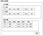
- FIG. 39 is a diagram showing an example of the inventory allocation screen according to the present embodiment.
- the order information selected on the screen shown in FIG. 37 when requesting the inventory allocation screen is extracted and displayed.
- a list of products corresponding to the order information is displayed, and a list of transaction information in which the user ID or company ID of the user (in this case, a major wholesaler) is the "buyer ID" is displayed.
- a screen like the one shown in FIG. 39 is realized by the service server 1 extracting information from the transaction information storage unit 105 in response to a request received from the user terminal 2b in S3506.
- the large wholesaler operates the user terminal 2b, selects the inventory to be allocated for the displayed order information from the transaction information displayed as "corresponding inventory”, and taps the "Confirm” button. do.
- the user terminal 2b requests the service server 1 to register inventory allocation (S3507).
- FIG. 40 is a diagram showing an example of information (hereinafter referred to as "inventory allocation information") transmitted from the user terminal 2b to the service server 1 in response to the inventory allocation registration request in S3507.
- the inventory allocation information includes a "target order information transaction ID" which is a transaction ID of transaction information as order information included in the "order information” list in FIG. It includes an "inventory allocation target transaction ID” which is a transaction ID of transaction information for which inventory is allocated.
- the parent transaction ID is updated by writing (S3508).
- actual inventory is allocated to orders placed in order from the downstream side, such as retail store, brokerage, and wholesaler, and order processing is completed.
- the premise is that in a system where the transaction flow is recorded by specifying the upstream transaction ID from the downstream transaction information using the "parent transaction ID,” an order is placed from the downstream side to the upstream vendor. However, it becomes possible to record the transaction flow using the "parent transaction ID".
- the extraction condition for the corresponding inventory list is transaction information in which the user ID or company ID of the vendor who allocates inventory (large wholesaler in the above case) is the "buyer ID", and the order
- transaction information selected as information and the "product" match are extracted. This is just an example, and since inventory is actually allocated according to the production area and standards specified in the order, "production area” and “standards” may also be used as extraction conditions.
- the "transaction date and time” may be used as a condition for the order date and time, or records with a "sales end” flag may be excluded.
- the ordering side may issue order information with a range of amounts, and the order receiving side may determine the amount within that range.
- Service server 2a, 2b, 2c, 2d User terminal 3 Store communication device 10 CPU 20 RAM 30 ROMs 40 HDD 50 I/F 60 LCD 70 Operation section 80 Bus 90 Near field communication antenna 101 Request processing section 102 Vendor information processing section 103 Vendor information storage section 104 Transaction information processing section 105 Transaction information storage section 200 Market sales management application 201 Operation reception section 202 Display processing section 203 Information communication Department
Landscapes
- Business, Economics & Management (AREA)
- Accounting & Taxation (AREA)
- Finance (AREA)
- Development Economics (AREA)
- Economics (AREA)
- Marketing (AREA)
- Strategic Management (AREA)
- Physics & Mathematics (AREA)
- General Business, Economics & Management (AREA)
- General Physics & Mathematics (AREA)
- Engineering & Computer Science (AREA)
- Theoretical Computer Science (AREA)
- Management, Administration, Business Operations System, And Electronic Commerce (AREA)
Priority Applications (2)
| Application Number | Priority Date | Filing Date | Title |
|---|---|---|---|
| JP2023553515A JP7383241B1 (ja) | 2022-03-22 | 2022-03-22 | 市場取引管理システム、市場取引管理プログラムおよび市場取引管理方法 |
| PCT/JP2022/013325 WO2023181140A1 (ja) | 2022-03-22 | 2022-03-22 | 市場取引管理システム、市場取引管理プログラムおよび市場取引管理方法 |
Applications Claiming Priority (1)
| Application Number | Priority Date | Filing Date | Title |
|---|---|---|---|
| PCT/JP2022/013325 WO2023181140A1 (ja) | 2022-03-22 | 2022-03-22 | 市場取引管理システム、市場取引管理プログラムおよび市場取引管理方法 |
Publications (1)
| Publication Number | Publication Date |
|---|---|
| WO2023181140A1 true WO2023181140A1 (ja) | 2023-09-28 |
Family
ID=88100223
Family Applications (1)
| Application Number | Title | Priority Date | Filing Date |
|---|---|---|---|
| PCT/JP2022/013325 Ceased WO2023181140A1 (ja) | 2022-03-22 | 2022-03-22 | 市場取引管理システム、市場取引管理プログラムおよび市場取引管理方法 |
Country Status (2)
| Country | Link |
|---|---|
| JP (1) | JP7383241B1 (https=) |
| WO (1) | WO2023181140A1 (https=) |
Families Citing this family (1)
| Publication number | Priority date | Publication date | Assignee | Title |
|---|---|---|---|---|
| JP7735021B1 (ja) * | 2025-07-07 | 2025-09-08 | 株式会社藤海産 | 市場取引管理システムおよび市場取引管理方法 |
Citations (6)
| Publication number | Priority date | Publication date | Assignee | Title |
|---|---|---|---|---|
| JP2009245160A (ja) * | 2008-03-31 | 2009-10-22 | Fujitsu Ltd | 取引データ登録プログラム、取引データ監視プログラム、取引データ登録装置、取引データ監視装置および取引データ追跡システム |
| JP2012178147A (ja) * | 2011-01-31 | 2012-09-13 | Yoshimitsu Kagiwada | 取引管理システムおよび取引管理プログラム |
| WO2014020711A1 (ja) * | 2012-07-31 | 2014-02-06 | 株式会社キーソフト | 取引管理システムおよび取引管理プログラム |
| JP2020525869A (ja) * | 2018-05-29 | 2020-08-27 | アリババ・グループ・ホールディング・リミテッドAlibaba Group Holding Limited | ブロックチェーンベースの商品追跡方法および装置 |
| JP2020170324A (ja) * | 2019-04-03 | 2020-10-15 | 株式会社春香園 | 電子商取引プログラム |
| JP2021096569A (ja) * | 2019-12-16 | 2021-06-24 | 株式会社三菱総合研究所 | 取引追跡システムおよび取引追跡プログラム |
-
2022
- 2022-03-22 JP JP2023553515A patent/JP7383241B1/ja active Active
- 2022-03-22 WO PCT/JP2022/013325 patent/WO2023181140A1/ja not_active Ceased
Patent Citations (6)
| Publication number | Priority date | Publication date | Assignee | Title |
|---|---|---|---|---|
| JP2009245160A (ja) * | 2008-03-31 | 2009-10-22 | Fujitsu Ltd | 取引データ登録プログラム、取引データ監視プログラム、取引データ登録装置、取引データ監視装置および取引データ追跡システム |
| JP2012178147A (ja) * | 2011-01-31 | 2012-09-13 | Yoshimitsu Kagiwada | 取引管理システムおよび取引管理プログラム |
| WO2014020711A1 (ja) * | 2012-07-31 | 2014-02-06 | 株式会社キーソフト | 取引管理システムおよび取引管理プログラム |
| JP2020525869A (ja) * | 2018-05-29 | 2020-08-27 | アリババ・グループ・ホールディング・リミテッドAlibaba Group Holding Limited | ブロックチェーンベースの商品追跡方法および装置 |
| JP2020170324A (ja) * | 2019-04-03 | 2020-10-15 | 株式会社春香園 | 電子商取引プログラム |
| JP2021096569A (ja) * | 2019-12-16 | 2021-06-24 | 株式会社三菱総合研究所 | 取引追跡システムおよび取引追跡プログラム |
Also Published As
| Publication number | Publication date |
|---|---|
| JPWO2023181140A1 (https=) | 2023-09-28 |
| JP7383241B1 (ja) | 2023-11-20 |
Similar Documents
| Publication | Publication Date | Title |
|---|---|---|
| US9898713B1 (en) | Methods systems and computer program products for monitoring inventory and prices | |
| US8046269B2 (en) | Auction based procurement system | |
| JP6118959B2 (ja) | 取引管理システムおよび取引管理プログラム | |
| US20110246326A1 (en) | System and method for enabling marketing channels in an ip marketplace | |
| US20150120486A1 (en) | System and method to compile and compare prices across multiple suppliers | |
| CN112561566A (zh) | 一种跨境进口门店分销商城平台系统 | |
| WO2008042822A2 (en) | Apparatuses, methods and systems for cross border procurement | |
| KR20150052929A (ko) | 상품 이용 후기를 이용한 온라인 쇼핑몰에서의 마케팅 시스템 및 방법 | |
| US20150178768A1 (en) | System and method for intermediating electronic commerce using offline transaction information | |
| WO2022241241A1 (en) | Consumer purchasing and inventory control assistant apparatus, system and methods | |
| KR100727425B1 (ko) | 단체 주도 구매 중개형 전자 상거래 시스템 및 이에적용되는 쇼핑몰 운영 시스템 | |
| JP2018142382A (ja) | 取引管理システムおよび取引管理プログラム | |
| JP7383241B1 (ja) | 市場取引管理システム、市場取引管理プログラムおよび市場取引管理方法 | |
| US20230005033A1 (en) | End-to-end food delivery ecosystem | |
| KR20240076058A (ko) | 실시간 농산물 시세를 반영한 공영 도매시장 pos 플랫폼 시스템 | |
| WO2015194519A1 (ja) | 販売価格算出装置および販売価格算出システム | |
| JP7256652B2 (ja) | Crmシステム | |
| US20160379248A1 (en) | Presenting opportunities for instant transactions | |
| KR101046602B1 (ko) | 사업자 간의 유통 절차 관리 시스템 | |
| KR100426388B1 (ko) | 포스 시스템을 이용하여 전자 상거래를 수행하는 방법 및시스템 | |
| JP7735021B1 (ja) | 市場取引管理システムおよび市場取引管理方法 | |
| JP7735020B1 (ja) | 市場取引管理システムおよび市場取引管理方法 | |
| US20230325869A1 (en) | Automated Product/Service Vending System and Method | |
| KR102157456B1 (ko) | 부동산 매물 정보제공 시스템 및 이를 이용한 부동산 중개방법 | |
| KR100690280B1 (ko) | 컴퓨터 네트워크를 이용한 그룹과의 전자상거래 제어 방법및 시스템 |
Legal Events
| Date | Code | Title | Description |
|---|---|---|---|
| WWE | Wipo information: entry into national phase |
Ref document number: 2023553515 Country of ref document: JP |
|
| 121 | Ep: the epo has been informed by wipo that ep was designated in this application |
Ref document number: 22933286 Country of ref document: EP Kind code of ref document: A1 |
|
| NENP | Non-entry into the national phase |
Ref country code: DE |
|
| 122 | Ep: pct application non-entry in european phase |
Ref document number: 22933286 Country of ref document: EP Kind code of ref document: A1 |