WO2023181137A1 - 第1無線通信装置及び第2無線通信装置 - Google Patents
第1無線通信装置及び第2無線通信装置 Download PDFInfo
- Publication number
- WO2023181137A1 WO2023181137A1 PCT/JP2022/013318 JP2022013318W WO2023181137A1 WO 2023181137 A1 WO2023181137 A1 WO 2023181137A1 JP 2022013318 W JP2022013318 W JP 2022013318W WO 2023181137 A1 WO2023181137 A1 WO 2023181137A1
- Authority
- WO
- WIPO (PCT)
- Prior art keywords
- wireless communication
- communication device
- frequency
- pdcch
- terminal device
- Prior art date
Links
- 230000006854 communication Effects 0.000 title claims abstract description 117
- 238000004891 communication Methods 0.000 title claims abstract description 109
- 230000005540 biological transmission Effects 0.000 claims abstract description 50
- 238000010586 diagram Methods 0.000 description 26
- 238000000034 method Methods 0.000 description 19
- 230000008569 process Effects 0.000 description 11
- 230000008859 change Effects 0.000 description 10
- 238000012545 processing Methods 0.000 description 8
- 230000007420 reactivation Effects 0.000 description 7
- 230000004913 activation Effects 0.000 description 6
- 238000012544 monitoring process Methods 0.000 description 4
- 238000005259 measurement Methods 0.000 description 3
- 230000009849 deactivation Effects 0.000 description 2
- 230000000737 periodic effect Effects 0.000 description 2
- 102100022734 Acyl carrier protein, mitochondrial Human genes 0.000 description 1
- 101000678845 Homo sapiens Acyl carrier protein, mitochondrial Proteins 0.000 description 1
- 230000003111 delayed effect Effects 0.000 description 1
- 238000005516 engineering process Methods 0.000 description 1
- 238000004519 manufacturing process Methods 0.000 description 1
- 238000013468 resource allocation Methods 0.000 description 1
- 230000004044 response Effects 0.000 description 1
- 239000007787 solid Substances 0.000 description 1
Images


Classifications
-
- H—ELECTRICITY
- H04—ELECTRIC COMMUNICATION TECHNIQUE
- H04W—WIRELESS COMMUNICATION NETWORKS
- H04W72/00—Local resource management
- H04W72/04—Wireless resource allocation
Definitions
- the present invention relates to a first wireless communication device and a second wireless communication device.
- Wireless communication systems using radio have been used.
- Wireless communication systems are also used, for example, within facilities such as factories.
- IoT Internet of Things
- a network may be configured on the terminal device side, and the terminal device side GW (UE-GW) may be responsible for communication.
- Traffic (data) in a terminal device occurs periodically (planned) (PDT: Periodic Deterministic Traffic), for example.
- Traffic is transmitted using, for example, CG (configured grant) radio resources (hereinafter sometimes referred to as CG resources) for uplink radio transmission and SPS (semi-persistent scheduling) for downlink radio transmission.
- CG configured grant radio resources
- SPS sub-persistent scheduling
- 3GPP TS36.133 LTE-A wireless measurement specifications 3GPP TS36.300 LTE-A Overview Specifications 3GPP TS36.211 LTE-A PHY channel specifications 3GPP TS36.212 LTE-A PHY encoding specification 3GPP TS36.213 LTE-A PHY procedure specifications 3GPP TS36.214 LTE-A PHY measurement specifications 3GPP TS36.321 LTE-A MAC specifications 3GPP TS36.322 LTE-A RLC specifications 3GPP TS36.323 LTE-A PDCP specifications 3GPP TS36.331 LTE-A RRC specifications 3GPP TS36.413 LTE-A S1 specifications 3GPP TS36.423 LTE-A X2 specifications 3GPP TS36.425 LTE-A Xn specifications 3GPP TR36.912 NR Radio Access Overview 3GPP TR38.913 NR requirements 3GPP TR38.913 NR requirements 3GPP TR38.801 NR Network Architecture Overview 3GP
- a terminal device may want to change the frequency of a CG resource, for example, in response to changes in wireless conditions. On the other hand, the terminal device may want to maintain the transmission cycle of the CG resource regardless of whether or not the frequency of the CG resource is changed. However, when the terminal device changes the frequency of the CG resource, the terminal device may not be able to maintain the transmission cycle of the CG resource.
- a control unit capable of resetting the frequency of the advance radio resource to the second wireless communication device and controlling implementation of the advance allocation type communication using the advance radio resource of the reset frequency.
- One disclosure is that the frequency of CG resources can be changed flexibly.
- FIG. 1 is a diagram showing an example of wireless communication in the wireless communication system 3.
- FIG. 2 is a diagram showing a configuration example of the wireless communication system 10.
- FIG. 3 is a diagram showing a configuration example of the terminal device 100.
- FIG. 4 is a diagram illustrating a configuration example of the base station device 200.
- FIG. 5 is a diagram showing an example of PDCCH in the case of Single configuration.
- FIG. 6 is a diagram showing an example of PDCCH in the case of multiple configuration.
- FIG. 7 is a diagram showing an example of PDCCH in the case of Single configuration.
- FIG. 8 is a diagram showing an example of PDCCH in case of multiple configuration.
- FIG. 9 is a diagram illustrating an example of radio resources for use case 1.
- FIG. 10 is a diagram illustrating an example of radio resources for use case 1.
- FIG. 11 is a diagram illustrating an example of radio resources for use case 2.
- FIG. 12 is a diagram illustrating an example of radio resources for use case 2.
- the wireless communication system 3 is a wireless communication system that includes a first wireless communication device 1 and a second wireless communication device 2.
- the first wireless communication device and the second wireless communication device 2 communicate wirelessly.
- the first wireless communication device and the second wireless communication device 2 perform pre-allocation type communication in which data is transmitted and received using wireless resources set in advance.
- FIG. 1 is a diagram showing an example of wireless communication in the wireless communication system 3.
- FIG. 1A is a diagram illustrating an example of a sequence for transmitting data from the second wireless communication device 2 to the first wireless communication device 1.
- the second wireless communication device 2 transmits data to the first wireless communication device 1 using wireless resources allocated in advance (hereinafter sometimes referred to as advance wireless resources) (S1).
- the frequency of the advance radio resource is the first frequency.
- the first wireless communication device 1 transmits a control signal to the second wireless communication device 2 (S2).
- the control signal is a message instructing to change the frequency of the advance radio resource used by the second wireless communication device.
- the control signal includes information to change the frequency of the advance radio resource to the second frequency.
- the second wireless communication device 2 transmits data to the first wireless communication device 1 using the preliminary wireless resource of the second frequency when the preliminary wireless resource transmission period comes (S3).
- FIG. 1B is a diagram showing an example of radio resources.
- the horizontal axis of radio resources indicates time (transmission timing).
- the second wireless communication device 2 uses the advance wireless resources of the first frequency in slot 2 to transmit data (S1).
- the second wireless communication device 2 receives a control signal from the first wireless communication device 1 (S2).
- the control signal includes information to change the frequency of the advance radio resource to the second frequency.
- the second wireless communication device 2 transmits data to the first wireless communication device 1 using the pre-wireless resource of the second frequency (S3).
- FIG. 2 is a diagram showing a configuration example of the wireless communication system 10.
- the wireless communication system 10 includes a base station device 200 and a terminal device 100.
- the wireless communication system 10 is, for example, a wireless communication system that is installed within the system and supports IIOT.
- the terminal device 100 is a communication device attached to equipment (device) within the system.
- Base station device 200 is a communication device installed within the system.
- the base station device 200 is compatible with various communication generations (eg, 5G, Beyond 5G, etc.), for example. Further, the base station device 200 may be configured with one device, or may be configured with a plurality of devices such as a CU (Central Unit) and a DU (Distributed Unit).
- CU Central Unit
- DU Distributed Unit
- the terminal device 100 periodically transmits data to the base station device 200.
- the terminal device 100 uses CG radio resources in periodic (PDT) data transmission.
- the terminal device 100 also supports semi-regular (ADT) data transmission.
- Semi-regular data transmission includes, for example, data transmission delayed from regular data transmission timing.
- the terminal device 100 supports changing the frequency of CG resources.
- terminal device 100 there is one terminal device 100 in FIG. 2, there may be a plurality of terminal devices. Further, in the following embodiments, data transmission from the terminal device 100 to the base station device 200 will be explained as an example, but communication between the terminal devices 100 and data transmission from the base station device 200 to the terminal device 100 will also be described. Similar processing can be applied.
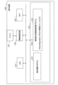
- FIG. 3 is a diagram showing a configuration example of the terminal device 100.
- the terminal device 100 includes a CPU (Central Processing Unit) 110, a storage 120, a memory 130, a wireless communication circuit 150, and an antenna 151.
- CPU Central Processing Unit
- the storage 120 is an auxiliary storage device such as a flash memory, an HDD (Hard Disk Drive), or an SSD (Solid State Drive) that stores programs and data.
- the storage 120 stores a terminal communication program 121 and a pre-assigned communication controlled program 122.
- the memory 130 is an area into which programs stored in the storage 120 are loaded.
- the memory 130 may also be used as an area for programs to store data.
- the wireless communication circuit 150 is a device that performs wireless communication with the base station device 200 and other terminal devices 100.
- the wireless communication circuit 150 includes an antenna 151.
- the antenna 151 includes, for example, a directional antenna that can control the direction of transmission and reception of radio waves.
- the CPU 110 is a processor that loads a program stored in the storage 120 into the memory 130, executes the loaded program, constructs each part, and implements each process.
- the CPU 110 executes the terminal communication program 121 to construct a second communication unit and perform terminal communication processing.
- the terminal communication process is a process of wirelessly communicating with the base station device 200 and other terminal devices 100.
- the CPU 110 executes the pre-allocation type communication controlled program 122 to construct the second control unit and performs the pre-allocated communication controlled processing.
- the pre-assigned communication controlled process is a process that controls the pre-assigned communication controlled process of the terminal device 100 in accordance with an instruction from the base station device 200.
- the terminal device 100 changes the frequency of the CG resource, for example, in the pre-allocation type communication controlled process.
- the terminal device 100 is instructed by the base station device 200 to change the frequency of the CG resource, and changes the frequency according to the instruction.
- the terminal device 100 executes the Reconfiguration PDCCH reception module 1221 included in the pre-assigned communication controlled program 122 to build a second control unit and perform Reconfiguration PDCCH reception processing.
- the Reconfiguration PDCCH reception process is a process of receiving the Reconfiguration PDCCH and changing the frequency of the CG resource. Reconfiguration PDCCH will be described later.
- FIG. 4 is a diagram illustrating a configuration example of the base station device 200.
- Base station device 200 includes CPU 210, storage 220, memory 230, wireless communication circuit 250, and antenna 251.
- the storage 220 is an auxiliary storage device such as a flash memory, HDD, or SSD that stores programs and data.
- the storage 220 stores a base station communication program 221 and a pre-allocation type communication control program 222.
- the memory 230 is an area into which programs stored in the storage 220 are loaded.
- the memory 230 may also be used as an area for programs to store data.
- the wireless communication circuit 250 is a device that performs wireless communication with the terminal device 100.
- the wireless communication circuit 250 includes an antenna 251.
- the antenna 251 includes, for example, a directional antenna that can control the direction of transmission and reception of radio waves.
- the CPU 210 is a processor that loads a program stored in the storage 220 into the memory 230, executes the loaded program, constructs each part, and implements each process.
- the CPU 210 executes the base station communication program 221 to build a communication unit and perform communication processing.
- the base station communication process is a process of performing wireless communication with the terminal device 100.
- the base station device 200 wirelessly connects with the terminal device 100, transmits data and control signals to the terminal device 100, and receives data from the terminal device 100.
- the CPU 210 executes the Reconfiguration PDCCH transmission module 2221 included in the pre-assigned communication control program 222 to build a control unit and perform Reconfiguration PDCCH transmission processing.
- the Reconfiguration PDCCH transmission process is a process of transmitting a Reconfiguration PDCCH including the changed frequency when changing the frequency of the CG resource of the terminal device 100.
- ⁇ CG type 1 Set the frequency and transmission cycle using RRC.
- the terminal device 100 starts a transmission cycle from the slot in which it receives RRC.
- ⁇ CG type 2 Set only the transmission cycle using RRC.
- the terminal device 100 starts a transmission cycle from the slot in which it receives an Activation PDCCH (Physical Downlink Control Channel) for setting the frequency.
- Activation PDCCH Physical Downlink Control Channel
- the terminal device 100 stops communication.
- ⁇ SPS Set the frequency and transmission cycle using RRC.
- the terminal device 100 starts a transmission cycle from the slot in which it receives the Activation PDCCH while receiving the configuration via RRC.
- the terminal device 100 stops communication. Furthermore, in each method, resetting of the transmission cycle is performed as follows.
- the terminal device 100 restarts the transmission cycle from the slot in which the RRC is received.
- the terminal device 100 restarts the transmission cycle from the slot in which the Reactivation PDCCH is received.
- the terminal device 100 restarts the transmission cycle from the slot in which the Reactivation PDCCH is received.
- the terminal device 100 flexibly changes the frequency and the transmission cycle (or maintains it). It may not be possible. Therefore, the wireless communication system 10 enables the use of Reconfiguration PDCCH.
- Reconfiguration PDCCH is an example of a control signal (reconfiguration control signal) that changes (reconfigures) the frequency of a CG resource.
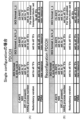
- FIG. 5 is a diagram showing an example of PDCCH in the case of Single configuration.
- FIG. 5A shows a normal PDCCH
- FIG. 5B shows a Reconfiguration PDCCH.
- normal PDCCH refers to PDCCH other than Reconfiguration PDCCH.
- FIG. 5 shows an example of information elements (fields) of PDCCH.
- MCS Modulation and Coding Scheme
- the frequency of the CG resource to be changed is set in FDRA (Frequency Domain Resource Allocation).
- the terminal device 100 changes the frequency of subsequent CG resources to the frequency set in FDRA.
- FIG. 6 is a diagram showing an example of PDCCH in the case of multiple configuration.
- 6A is a normal PDCCH
- FIG. 6B is a Reconfiguration PDCCH.
- 0 is set in the MCS.
- the frequency of the CG resource to be changed to FDRA is set.
- the terminal device 100 changes the frequency of subsequent CG resources to the frequency set in FDRA.
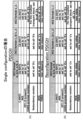
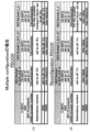
- FIG. 7 is a diagram showing an example of PDCCH in the case of Single configuration.
- FIG. 7A shows a normal PDCCH
- FIG. 7B shows a Reconfiguration PDCCH.
- a new MCS value is set in the MCS.
- the frequency of the CG resource to be changed is set in the FDRA.
- the terminal device 100 changes the frequency of subsequent CG resources to the frequency set in FDRA.
- FIG. 8 is a diagram showing an example of PDCCH in the case of multiple configuration.
- FIG. 8A shows a normal PDCCH
- FIG. 8B shows a Reconfiguration PDCCH.
- a new MCS value is set in the MCS.
- the frequency of the CG resource to be changed is set in the FDRA.
- the terminal device 100 changes the frequency of subsequent CG resources to the frequency set in FDRA.
- FIG. 9 is a diagram illustrating an example of radio resources for use case 1.
- Use case 1 is a case in which transmission of CG resources is started in slot 2 and the transmission cycle is maintained at 5 slots.
- “RF ON” and “RF OFF” at the bottom of the figure indicate ON and OFF of the RF section of the terminal device 100.
- the radio resource indicates frequency (f) in the vertical direction and time (t) in the horizontal direction.
- the K2 value in FIG. 1 is 1. The K2 value indicates the slot length from when the PDCCH is received until the start of the transmission cycle is applied.
- the terminal device 100 receives the Activation PDCCH in slot 1 (S10).
- the terminal device 100 monitors the PDCCH for retransmission for a predetermined period because retransmission of the CG resource may occur (S11).
- the terminal device 100 After monitoring for a predetermined period, the terminal device 100 turns off the RF section in slot 5 (S12).
- Reactivation PDCCH includes frequency information to be changed.
- the terminal device 100 uses the CG resource of the changed frequency (slot 7) and monitors the retransmission PDCCH for a predetermined period (S14).
- FIG. 10 is a diagram showing an example of radio resources for use case 1.
- Reconfiguration PDCCH is used to change the frequency of the CG resource.
- the terminal device 100 turns on the RF unit in slot 2 and starts transmitting CG resources (S20). Note that in FIG. 10, since the terminal device 100 does not assume a frequency change by receiving the Activation PDCCH and the Reactivation PDCCH, the RF section can be turned off until the timing of transmitting the CG resource.
- the terminal device 100 monitors the PDCCH for retransmission for a predetermined period because retransmission of the CG resource may occur (S21).
- the terminal device 100 monitors the Reconfiguration PDCCH. Then, the terminal device 100 receives the Reconfiguration PDCCH in slot 4 and turns off the RF section (S22).
- the terminal device 100 turns on the RF section in slot 7 (S23), uses the CG resource of the changed frequency, and monitors the retransmission PDCCH for a predetermined period (S24).
- the terminal device 100 does not use the reception of the Reconfiguration PDCCH as a trigger for changing the transmission cycle of the CG resource. Therefore, the Reconfiguration PDCCH can maintain the transmission cycle of CG resources while changing the frequency.
- the terminal device 100 can realize power saving by receiving the Reconfiguration PDCCH while monitoring the PDCCH for retransmission.
- the RF section can be turned off in slots 1 and 6, the power consumption of the terminal device 100 is reduced compared to FIG. 9.
- FIG. 11 is a diagram showing an example of radio resources for use case 2.
- Use case 2 is an example in which the frequency of the CG resource is changed and transmitted when data retransmission occurs.
- Reconfiguration PDCCH is used to change the frequency of the CG resource.
- the terminal device 100 transmits data using the CG resource of slot 2. Then, the terminal device 100 receives, for example, a retransmission PDCCH for which data transmission using the CG resource has failed and retransmission is requested (S30).
- the terminal device 100 retransmits data using a resource (retransmission PUSCH: Physical Uplink Shared Channel) whose frequency has been changed from the CG resource (S31).
- a resource retransmission PUSCH: Physical Uplink Shared Channel
- the terminal device 100 receives a Reconfiguration PDCCH that changes the frequency of the CG resource to the frequency used for retransmission (S32).
- the terminal device 100 uses the changed frequency (the frequency used for retransmission) as the frequency of the CG resource and transmits data (S33). Thereafter, CG resources are transmitted at the changed frequency.
- FIG. 12 is a diagram showing an example of radio resources for use case 2.
- the frequency of the CG resource is not changed in Reconfiguration PDCCH, and the frequency used at the time of retransmission is continued to be used.
- the terminal device 100 transmits data using the CG resource of slot 2. Then, the terminal device 100 receives, for example, a retransmission PDCCH for which data transmission using the CG resource has failed and retransmission is requested (S40).
- the terminal device 100 retransmits the data using a resource (retransmission PUSCH) whose frequency has been changed from the CG resource (S41).
- the terminal device 100 sets the frequency used for retransmission as the frequency of the CG resource and transmits data (S42). Thereafter, the CG resource is transmitted on the frequency used for retransmission.
- the expiration date indicates, for example, how long the changed frequency resource is valid. For example, it may be set whether or not the changed frequency resource is changed only once (from the second time onwards, the frequency resource before the change is used). Further, for example, it may be set that the changed frequency resource is changed only N times (N is an integer of 1 or more). Furthermore, for example, the changed frequency resource may be set to have no expiration date and to be valid thereafter.
- the requirements described in the first embodiment, second embodiment, and other embodiments may be combined. Further, the requirements described in the first embodiment, the second embodiment, and other embodiments may be used depending on, for example, wireless conditions, system requirements, etc.
- the shift amount (width) described in the first embodiment, the second embodiment, and other embodiments is similar to the shift amount (width) described in the first embodiment, the second embodiment, and other embodiments. , frame).
- Wireless communication system 10 Wireless communication system 100: Terminal device 110: CPU 120: Storage 121: Terminal communication program 122: Pre-allocated communication controlled program 1221: PDCCH reception module 130: Memory 150: Wireless communication circuit 151: Antenna 200: Base station device 210: CPU 220: Storage 221: Base station communication program 222: Pre-assigned communication control program 2221: PDCCH transmission module 230: Memory 250: Wireless communication circuit 251: Antenna
Landscapes
- Engineering & Computer Science (AREA)
- Computer Networks & Wireless Communication (AREA)
- Signal Processing (AREA)
- Mobile Radio Communication Systems (AREA)
Abstract
第1無線通信装置であって、事前に設定された無線リソースを利用して第2無線通信装置と通信を行う事前割当型通信において、事前に設定された事前無線リソースの送信周期を維持しつつ、前記事前無線リソースの周波数を前記第2無線通信装置に再設定でき、前記再設定した周波数の前記事前無線リソースを使用した前記事前割当型通信の実施を制御できる制御部を有する。
Description
本発明は、第1無線通信装置及び第2無線通信装置に関する。
近年、無線を利用した無線通信システムが使用されている。無線通信システムは、例えば、工場などの施設内においても使用される。
工場内では、例えば、製造機器や装置と制御監視システムとを無線接続し、IoT(Internet of Things)を使用してデータや制御信号を送受信する。工場内で使用されるIoTを、特にIIoT(Industrial IoT)と呼ぶ場合がある。
IIoTにおいて、例えば、端末装置側でネットワークを構成し、端末装置側GW(UE-GW)が通信を担う場合がある。端末装置におけるトラヒック(データ)は、例えば、定期的(計画的)に発生する(PDT:Periodic Deterministic Traffic)。トラヒックは、例えば、上り無線伝送としてはCG(configured grant)の無線リソース(以降、CGリソースと呼ぶ場合がある)、下り無線伝送としてはSPS(semi-persistent scheduling)を用いて送信される。
IIoTに関する技術としては、以下の先行技術文献に記載されている。
3GPP TS36.133 LTE-A 無線測定仕様
3GPP TS36.300 LTE-A 概要仕様
3GPP TS36.211 LTE-A PHYチャネル仕様
3GPP TS36.212 LTE-A PHY符号化仕様
3GPP TS36.213 LTE-A PHY手順仕様
3GPP TS36.214 LTE-A PHY測定仕様
3GPP TS36.321 LTE-A MAC仕様
3GPP TS36.322 LTE-A RLC仕様
3GPP TS36.323 LTE-A PDCP仕様
3GPP TS36.331 LTE-A RRC仕様
3GPP TS36.413 LTE-A S1仕様
3GPP TS36.423 LTE-A X2仕様
3GPP TS36.425 LTE-A Xn仕様
3GPP TR36.912 NR 無線アクセス概要
3GPP TR38.913 NR 要求条件
3GPP TR38.913 NR 要求条件
3GPP TR38.801 NR ネットワークアーキテクチャ概要
3GPP TR38.802 NR PHY概要
3GPP TR38.803 NR RF概要
3GPP TR38.804 NR L2概要
3GPP TR38.900 NR 高周波概要
3GPP TS38.300 NR 概要仕様
3GPP TS37.340 NR 多元接続概要仕様
3GPP TS38.201 NR PHY仕様概要仕様
3GPP TS38.202 NR PHYサービス概要仕様
3GPP TS38.211 NR PHYチャネル仕様
3GPP TS38.212 NR PHY符号化仕様
3GPP TS38.213 NR PHYデータチャネル手順仕様
3GPP TS38.214 NR PHYコントロールチャネル手順仕様
3GPP TS38.215 NR PHY測定仕様
3GPP TS38.321 NR MAC仕様
3GPP TS38.322 NR RLC仕様
3GPP TS38.323 NR PDCP仕様
3GPP TS37.324 NR SDAP仕様
3GPP TS38.331 NR RRC仕様
3GPP TS38.401 NR アーキテクチャ概要仕様
3GPP TS38.410 NR コアネットワーク概要仕様
3GPP TS38.413 NR コアネットワークAP仕様
3GPP TS38.420 NR Xnインタフェース概要仕様
3GPP TS38.423 NR XnAP仕様
3GPP TS38.470 NR F1インタフェース概要仕様
3GPP TS38.473 NR F1AP仕様
端末装置は、例えば、無線状態の変化などに応じて、CGリソースの周波数を変更したい場合がある。一方、端末装置は、CGリソースの周波数の変更の有無に関わらず、CGリソースの送信周期を維持したい場合がある。しかし、端末装置は、CGリソースの周波数を変更すると、CGリソースの送信周期を維持できない場合がある。
そこで、CGリソースの周波数をフレキシブルに変更できる、第1無線通信装置及び第2無線通信装置を提供する。
第1無線通信装置であって、事前に設定された無線リソースを利用して第2無線通信装置と通信を行う事前割当型通信において、事前に設定された事前無線リソースの送信周期を維持しつつ、前記事前無線リソースの周波数を前記第2無線通信装置に再設定でき、前記再設定した周波数の前記事前無線リソースを使用した前記事前割当型通信の実施を制御できる制御部を有する。
一開示は、CGリソースの周波数をフレキシブルに変更できる。
[第1の実施の形態]
第1の実施の形態について説明する。
第1の実施の形態について説明する。
無線通信システム3は、第1無線通信装置1と第2無線通信装置2を有する無線通信システムである。第1無線通信装置と第2無線通信装置2は、無線を介して通信を行う。無線通信システム3において、第1無線通信装置と第2無線通信装置2は、事前に設定された無線リソースを使用してデータを送受信する、事前割当型通信を行う。
図1は、無線通信システム3における、無線通信の例を示す図である。図1Aは、第2無線通信装置2から第1無線通信装置1にデータを送信するシーケンスの例を示す図である。
第2無線通信装置2は、事前に割り当てられた無線リソース(以降、事前無線リソースと呼ぶ場合がある)を使用して、第1無線通信装置1にデータを送信する(S1)。事前無線リソースの周波数は、第1周波数である。
そして、第1無線通信装置1は、第2無線通信装置2に、制御信号を送信する(S2)。制御信号は、第2無線通信装置が使用する事前無線リソースの周波数の変更を指示するメッセージである。制御信号は、事前無線リソースの周波数を、第2周波数に変更する旨の情報を含む。
第2無線通信装置2は、事前無線リソースの送信周期になると、第2周波数の事前無線リソースを使用して、第1無線通信装置1にデータを送信する(S3)。
図1Bは、無線リソースの例を示す図である。図1Bにおいて、無線リソースの横軸は時間(送信タイミング)を示す。第2無線通信装置2は、スロット2において、第1周波数の事前無線リソースを使用し、データを送信する(S1)。
そして、第2無線通信装置2は、第1無線通信装置1から制御信号を受信する(S2)。制御信号は、事前無線リソースの周波数を、第2周波数に変更する旨の情報を含む。
そして、第2無線通信装置2は、事前無線リソースの送信周期(スロット7)になると、第2周波数の事前無線リソースを使用して、第1無線通信装置1にデータを送信する(S3)。
第1の実施の形態では、制御信号で事前無線リソースの周波数を変更することで、事前無線リソースの送信周期を維持しつつ(送信タイミングを変更せず)、周波数を変更することができる。
[第2の実施の形態]
第2の実施の形態について説明する。
[第2の実施の形態]
第2の実施の形態について説明する。
<無線通信システム10について>
図2は、無線通信システム10の構成例を示す図である。無線通信システム10は、基地局装置200及び端末装置100を有する。無線通信システム10は、例えば、システム内に設置される、IIOTに対応する無線通信システムである。
図2は、無線通信システム10の構成例を示す図である。無線通信システム10は、基地局装置200及び端末装置100を有する。無線通信システム10は、例えば、システム内に設置される、IIOTに対応する無線通信システムである。
端末装置100は、システム内の機器(装置)に取り付けられた通信装置である。基地局装置200は、システム内に設置される通信装置である。
基地局装置200は、例えば、様々な通信世代(例えば、5GやBeyond5Gなど)に対応する。また、基地局装置200は、1台で構成されてもよいし、CU(Central Unit)とDU(Distributed Unit)などの複数台で構成されてもよい。
端末装置100は、例えば、定期的にデータを基地局装置200に送信する。端末装置100は、定期的(PDT)なデータ送信において、CGの無線リソースを使用する。また、端末装置100は、準定期的(ADT)なデータ送信にも対応する。準定期的なデータ送信とは、例えば、定期的なデータ送信タイミングから遅延して発生したデータの送信を含む。さらに、端末装置100は、CGリソースの周波数の変更に対応する。
なお、図2において、端末装置100は1台であるが、複数台存在してもよい。また、以降の実施例において、端末装置100から基地局装置200へのデータ送信を例として説明するが、端末装置100間の通信や、基地局装置200から端末装置100へのデータ送信についても、同様の処理を適用することができる。
<端末装置100の構成例>
図3は、端末装置100の構成例を表す図である。端末装置100は、CPU(Central Processing Unit)110、ストレージ120、メモリ130、無線通信回路150、及びアンテナ151を有する。
図3は、端末装置100の構成例を表す図である。端末装置100は、CPU(Central Processing Unit)110、ストレージ120、メモリ130、無線通信回路150、及びアンテナ151を有する。
ストレージ120は、プログラムやデータを記憶する、フラッシュメモリ、HDD(Hard Disk Drive)、又はSSD(Solid State Drive)などの補助記憶装置である。ストレージ120は、端末通信プログラム121、事前割当型通信被制御プログラム122を記憶する。
メモリ130は、ストレージ120に記憶されているプログラムをロードする領域である。また、メモリ130は、プログラムがデータを記憶する領域としても使用されてもよい。
無線通信回路150は、基地局装置200や他の端末装置100と無線通信を行う装置である。無線通信回路150は、無線通信回路150は、アンテナ151を有する。アンテナ151は、例えば、電波の送受信の方向を制御可能である指向性アンテナを含む。
CPU110は、ストレージ120に記憶されているプログラムを、メモリ130にロードし、ロードしたプログラムを実行し、各部を構築し、各処理を実現するプロセッサである。
CPU110は、端末通信プログラム121を実行することで、第2通信部を構築し、端末通信処理を行う。端末通信処理は、基地局装置200や他の端末装置100と無線通信を行う処理である。
CPU110は、事前割当型通信被制御プログラム122を実行することで、第2制御部を構築し、事前割当型通信被制御処理を行う。事前割当型通信被制御処理は、端末装置100の事前割当型通信被制御を、基地局装置200の指示に応じて、制御する処理である。端末装置100は、事前割当型通信被制御処理において、例えば、CGリソースの周波数を変更する。端末装置100は、基地局装置200から、CGリソースの周波数を変更するよう指示され、指示に従って周波数を変更する。
端末装置100は、事前割当型通信被制御プログラム122に含まれるReconfiguration PDCCH受信モジュール1221を実行することで、第2制御部を構築し、Reconfiguration PDCCH受信処理を行う。Reconfiguration PDCCH受信処理は、Reconfiguration PDCCHを受信し、CGリソースの周波数を変更する処理である。Reconfiguration PDCCHについては、後述する。
<基地局装置200の構成例>
図4は、基地局装置200の構成例を表す図である。基地局装置200は、CPU210、ストレージ220、メモリ230、無線通信回路250、及びアンテナ251を有する。
図4は、基地局装置200の構成例を表す図である。基地局装置200は、CPU210、ストレージ220、メモリ230、無線通信回路250、及びアンテナ251を有する。
ストレージ220は、プログラムやデータを記憶する、フラッシュメモリ、HDD、又はSSDなどの補助記憶装置である。ストレージ220は、基地局通信プログラム221、事前割当型通信制御プログラム222を記憶する。
メモリ230は、ストレージ220に記憶されているプログラムをロードする領域である。また、メモリ230は、プログラムがデータを記憶する領域としても使用されてもよい。
無線通信回路250は、端末装置100と無線通信を行う装置である。無線通信回路250は、無線通信回路250は、アンテナ251を有する。アンテナ251は、例えば、電波の送受信の方向を制御可能である指向性アンテナを含む。
CPU210は、ストレージ220に記憶されているプログラムを、メモリ230にロードし、ロードしたプログラムを実行し、各部を構築し、各処理を実現するプロセッサである。
CPU210は、基地局通信プログラム221を実行することで、通信部を構築し、通信処理を行う。基地局通信処理は、端末装置100と無線通信を行う処理である。基地局装置200は、基地局通信処理において、端末装置100と無線接続し、端末装置100にデータや制御信号を送信したり、端末装置100からデータを受信したりする。
CPU210は、事前割当型通信制御プログラム222が有するReconfiguration PDCCH送信モジュール2221を実行することで、制御部を構築し、Reconfiguration PDCCH送信処理を行う。Reconfiguration PDCCH送信処理は、端末装置100のCGリソースの周波数を変更するとき、変更後の周波数を含むReconfiguration PDCCHを送信する処理である。
<CGリソースの周波数及び送信周期について>
CGリソースの送信周期の開始について説明する。CGリソースの送信周期は、例えば、以下の3方式がある。
CGリソースの送信周期の開始について説明する。CGリソースの送信周期は、例えば、以下の3方式がある。
・CGタイプ1:周波数、送信周期をRRCで設定する。端末装置100は、RRCを受信したスロットから送信周期を開始する。
・CGタイプ2:送信周期のみをRRCで設定する。端末装置100は、周波数を設定するActivation PDCCH(Physical Downlink Control Channel)を受信したスロットから送信周期を開始する。一方、端末装置100は、Deactivation PDCCHを受信すると、通信を停止する。
・SPS:周波数、送信周期をRRCで設定する。端末装置100は、RRCで設定を受信した状態で、Activation PDCCHを受信したスロットから送信周期を開始する。一方、端末装置100は、Deactivation PDCCHを受信すると、通信を停止する。 また、各方式において、送信周期の再設定は、以下のように実施される。
・CGタイプ1:端末装置100は、RRCを受信したスロットから送信周期を再開する。
・CGタイプ2:端末装置100は、Reactivation PDCCHを受信したスロットから送信周期を再開する。
・SPS:端末装置100は、Reactivation PDCCHを受信したスロットから送信周期を再開する。
RRCやReactivation PDCCH(Activation PDCCHを含む。以降同様)を使用し、周波数や送信周期を変更する方式では、端末装置100は、周波数の変更と送信周期の変更(又は維持)を、フレキシブルに実施することができない場合がある。そこで、無線通信システム10は、Reconfiguration PDCCHを使用することができるようにする。
<Reconfiguration PDCCH>
以下、4パターンのReconfiguration PDCCHの例を説明する。Reconfiguration PDCCHは、CGリソースの周波数を変更(再設定)する制御信号(再設定用制御信号)の一例である。
以下、4パターンのReconfiguration PDCCHの例を説明する。Reconfiguration PDCCHは、CGリソースの周波数を変更(再設定)する制御信号(再設定用制御信号)の一例である。
図5は、Single configurationの場合のPDCCHの例を示す図である。図5Aは、通常のPDCCHであり、図5Bは、Reconfiguration PDCCHである。なお、通常のPDCCHは、Reconfiguration PDCCH以外のPDCCHを示す。また、図5は、PDCCHの情報要素(フィールド)の例を示す。
Reconfiguration PDCCHは、MCS(Modulation and Coding Scheme)に0が設定される。MCSは、変調方式と符号化方式に組み合わせを示す。MCSは、CS-RNTIかつNDI=0の場合、使用されない(意味をなさない)値となるため、MCSに0が設定されてもよい。
Reconfiguration PDCCHは、FDRA(Frequency Domain Resource Allocation)に、変更するCGリソースの周波数が設定される。端末装置100は、以降のCGリソースの周波数を、FDRAに設定される周波数に変更する。
図6は、Multiple configurationの場合のPDCCHの例を示す図である。図6Aは、通常のPDCCHであり、図6Bは、Reconfiguration PDCCHである。
Reconfiguration PDCCHは、MCSに0が設定される。
Reconfiguration PDCCHは、FDRAに変更するCGリソースの周波数が設定される。端末装置100は、以降のCGリソースの周波数を、FDRAに設定される周波数に変更する。
図7は、Single configurationの場合のPDCCHの例を示す図である。図7Aは、通常のPDCCHであり、図7Bは、Reconfiguration PDCCHである。
Reconfiguration PDCCHは、Redundancy versionにオール1が設定される。CGリソースのRedundancy versionがオール1と反転させることは、仕様として規定される。
Reconfiguration PDCCHは、MCSに新たなMCS値が設定される。
Reconfiguration PDCCHは、FDRAに、変更するCGリソースの周波数が設定される。端末装置100は、以降のCGリソースの周波数を、FDRAに設定される周波数に変更する。
図8は、Multiple configurationの場合のPDCCHの例を示す図である。図8Aは、通常のPDCCHであり、図8Bは、Reconfiguration PDCCHである。
Reconfiguration PDCCHは、Redundancy versionにオール1が設定される。上記と同様に反転は問題ない。
Reconfiguration PDCCHは、MCSに新たなMCS値が設定される。
Reconfiguration PDCCHは、FDRAに、変更するCGリソースの周波数が設定される。端末装置100は、以降のCGリソースの周波数を、FDRAに設定される周波数に変更する。
<Reconfiguration PDCCHのユースケース>
図9は、ユースケース1の無線リソースの例を示す図である。ユースケース1は、スロット2でCGリソースの送信を開始し、送信周期5スロットを維持するケースである。図下部の「RF ON」、「RF OFF」は、端末装置100のRF部のON、OFFを示す。また、無線リソースは、縦方向に周波数(f)、横方向に時間(t)を示す。また、図1におけるK2値は1である。K2値は、PDCCHを受信してから、送信周期の開始が適用されるまでのスロット長を示す。
図9は、ユースケース1の無線リソースの例を示す図である。ユースケース1は、スロット2でCGリソースの送信を開始し、送信周期5スロットを維持するケースである。図下部の「RF ON」、「RF OFF」は、端末装置100のRF部のON、OFFを示す。また、無線リソースは、縦方向に周波数(f)、横方向に時間(t)を示す。また、図1におけるK2値は1である。K2値は、PDCCHを受信してから、送信周期の開始が適用されるまでのスロット長を示す。
端末装置100は、Activation PDCCHをスロット1で受信する(S10)。端末装置100は、Activation PDCCHを受信した次のスロット(K2=1であるため)から、CGリソースの送信を開始する。
端末装置100は、CGリソースの再送が発生する可能性があるため、所定期間、再送用PDCCHをモニタリングする(S11)。
そして、端末装置100は、所定期間モニタリングした後、スロット5において、RF部をOFFにする(S12)。
そして、端末装置100は、CGリソースを送信する(スロット7)となる前のスロット6から、RF部をONにし、Reactivation PDCCHモニタを開始し、Reactivation PDCCHを受信する(S13)。Reactivation PDCCHには、変更する周波数情報が含まれる。
端末装置100は、変更された周波数のCGリソースを使用し(スロット7)、所定期間、再送用PDCCHをモニタリングする(S14)。
図10は、ユースケース1の無線リソースの例を示す図である。図10においては、Reconfiguration PDCCHを使用し、CGリソースの周波数を変更する。
端末装置100は、スロット2でRF部をONにし、CGリソースの送信を開始する(S20)。なお、図10において、端末装置100は、Activation PDCCH及びReactivation PDCCHを受信することによる周波数変更を想定していないため、CGリソースの送信タイミングまで、RF部をOFFとすることができる。
端末装置100は、CGリソースの再送が発生する可能性があるため、所定期間、再送用PDCCHをモニタリングする(S21)。
また、端末装置100は、Reconfiguration PDCCHをモニタリングする。そして、端末装置100は、スロット4において、Reconfiguration PDCCHを受信し、RF部をOFFにする(S22)。
端末装置100は、スロット7でRF部をONにし(S23)、変更された周波数のCGリソースを使用し、所定期間、再送用PDCCHをモニタリングする(S24)。
このように、端末装置100は、Reconfiguration PDCCHの受信をCGリソースの送信周期変更のトリガとしない。よって、Reconfiguration PDCCHは、周波数を変更しつつ、CGリソースの送信周期を維持することができる。
さらに、端末装置100は、Reconfiguration PDCCHを再送用PDCCHのモニタリング中に受信することで、省電力を実現できる。図10においては、スロット1、6においてRF部をOFFとすることができるため、図9と比較し、端末装置100の消費電力が減少する。
図11は、ユースケース2の無線リソースの例を示す図である。ユースケース2は、データ再送が発生したときに、CGリソースの周波数を変更して送信する場合の例である。図11においては、Reconfiguration PDCCHを使用し、CGリソースの周波数を変更する。
端末装置100は、スロット2のCGリソースでデータを送信する。そして、端末装置100は、例えば、CGリソースでのデータ送信が失敗し、再送を要求される再送用PDCCHを受信する(S30)。
端末装置100は、CGリソースから周波数を変更したリソース(再送PUSCH:Physical Uplink Shared Channel)でデータを再送する(S31)。
端末装置100は、CGリソースの周波数を、再送に使用した周波数に変更するReconfiguration PDCCHを受信する(S32)。
端末装置100は、次の送信周期において、変更した周波数(再送に使用した周波数)を、CGリソースの周波数とし、データを送信する(S33)。以降、CGリソースは、変更した周波数で送信される。
図12は、ユースケース2の無線リソースの例を示す図である。図12においては、Reconfiguration PDCCHでCGリソースの周波数を変更せず、再送時に使用した周波数を引き続き使用する。
端末装置100は、スロット2のCGリソースでデータを送信する。そして、端末装置100は、例えば、CGリソースでのデータ送信が失敗し、再送を要求される再送用PDCCHを受信する(S40)。
端末装置100は、CGリソースから周波数を変更したリソース(再送PUSCH)でデータを再送する(S41)。
端末装置100は、次の送信周期において、再送に使用した周波数を、CGリソースの周波数とし、データを送信する(S42)。以降、CGリソースは、再送に使用した周波数で送信される。
[その他の実施の形態]
周波数リソースを変更する場合、変更された周波数リソースの有効期限が設定できてもよい。有効期限は、例えば、変更した周波数リソースが、どこまで有効かを示すものである。例えば、変更された周波数リソースは、1回のみの変更である(2回目以降は、変更前の周波数リソースを使用する)のか否かが設定されてもよい。また、例えば、変更された周波数リソースは、N(Nは1以上の整数)回のみの変更であることが設定されてもよい。さらに、例えば、変更された周波数リソースは、有効期限がなく、以降有効であることが設定されてもよい。
周波数リソースを変更する場合、変更された周波数リソースの有効期限が設定できてもよい。有効期限は、例えば、変更した周波数リソースが、どこまで有効かを示すものである。例えば、変更された周波数リソースは、1回のみの変更である(2回目以降は、変更前の周波数リソースを使用する)のか否かが設定されてもよい。また、例えば、変更された周波数リソースは、N(Nは1以上の整数)回のみの変更であることが設定されてもよい。さらに、例えば、変更された周波数リソースは、有効期限がなく、以降有効であることが設定されてもよい。
第1の実施の形態、第2の実施の形態、及びその他の実施の形態に記載された要件は、それぞれ組み合わせてもよい。また、第1の実施の形態、第2の実施の形態、及びその他の実施の形態に記載された要件は、例えば、無線状態、システム要件などに応じて、使い分けてもよい。
また、第1の実施の形態、第2の実施の形態、及びその他の実施の形態に記載されたシフト量(幅)は、スロット数以外に、類似の概念(例えば、時間、単位時間、タイミング、フレーム)で置き換えられてもよい。
3 :無線通信システム
10 :無線通信システム
100 :端末装置
110 :CPU
120 :ストレージ
121 :端末通信プログラム
122 :事前割当型通信被制御プログラム
1221 :PDCCH受信モジュール
130 :メモリ
150 :無線通信回路
151 :アンテナ
200 :基地局装置
210 :CPU
220 :ストレージ
221 :基地局通信プログラム
222 :事前割当型通信制御プログラム
2221 :PDCCH送信モジュール
230 :メモリ
250 :無線通信回路
251 :アンテナ
10 :無線通信システム
100 :端末装置
110 :CPU
120 :ストレージ
121 :端末通信プログラム
122 :事前割当型通信被制御プログラム
1221 :PDCCH受信モジュール
130 :メモリ
150 :無線通信回路
151 :アンテナ
200 :基地局装置
210 :CPU
220 :ストレージ
221 :基地局通信プログラム
222 :事前割当型通信制御プログラム
2221 :PDCCH送信モジュール
230 :メモリ
250 :無線通信回路
251 :アンテナ
Claims (6)
- 第1無線通信装置であって、
事前に設定された無線リソースを利用して第2無線通信装置と通信を行う事前割当型通信において、
事前に設定された事前無線リソースの送信周期を維持しつつ、前記事前無線リソースの周波数を前記第2無線通信装置に再設定でき、前記再設定した周波数の前記事前無線リソースを使用した前記事前割当型通信の実施を制御できる制御部を
有する第1無線通信装置。 - 前記制御部は、前記再設定において、前記再設定する周波数を含む再設定用制御信号を、前記第2無線通信装置に送信する
請求項1記載の第1無線通信装置。 - 前記再設定用制御信号は、PDCCH(Physical Downlink Control Channel)に含まれる
請求項2記載の第1無線通信装置。 - 前記再設定用制御信号は、前記PDCCHの所定の3種のフィールドの値それぞれに、再設定用制御信号であることを示す値が設定される
請求項3記載の第1無線通信装置。 - 前記再設定用制御信号は、前記PDCCHの所定の2種のフィールドの値それぞれに、再設定用制御信号であることを示す値が設定される
請求項3記載の第1無線通信装置。 - 第2無線通信装置であって、
事前に設定された無線リソースを利用して第1無線通信装置と通信を行う事前割当型通信において、
前記第1無線通信装置に、事前に設定された事前無線リソースの周波数を再設定され、前記事前無線リソースの送信周期を維持しつつ、前記再設定された周波数の前記事前無線リソースを使用した前記事前割当型通信の実施できる第2制御部
を有する第2無線通信装置。
Priority Applications (1)
| Application Number | Priority Date | Filing Date | Title |
|---|---|---|---|
| PCT/JP2022/013318 WO2023181137A1 (ja) | 2022-03-22 | 2022-03-22 | 第1無線通信装置及び第2無線通信装置 |
Applications Claiming Priority (1)
| Application Number | Priority Date | Filing Date | Title |
|---|---|---|---|
| PCT/JP2022/013318 WO2023181137A1 (ja) | 2022-03-22 | 2022-03-22 | 第1無線通信装置及び第2無線通信装置 |
Publications (1)
| Publication Number | Publication Date |
|---|---|
| WO2023181137A1 true WO2023181137A1 (ja) | 2023-09-28 |
Family
ID=88100235
Family Applications (1)
| Application Number | Title | Priority Date | Filing Date |
|---|---|---|---|
| PCT/JP2022/013318 WO2023181137A1 (ja) | 2022-03-22 | 2022-03-22 | 第1無線通信装置及び第2無線通信装置 |
Country Status (1)
| Country | Link |
|---|---|
| WO (1) | WO2023181137A1 (ja) |
Citations (3)
| Publication number | Priority date | Publication date | Assignee | Title |
|---|---|---|---|---|
| WO2019031267A1 (ja) * | 2017-08-09 | 2019-02-14 | ソニー株式会社 | 通信装置および方法 |
| WO2021215098A1 (ja) * | 2020-04-24 | 2021-10-28 | パナソニック インテレクチュアル プロパティ コーポレーション オブ アメリカ | 端末及び通信方法 |
| JP2021534628A (ja) * | 2018-08-09 | 2021-12-09 | コンヴィーダ ワイヤレス, エルエルシー | 構成済みグラントを使用したul送信のためのuci設計 |
-
2022
- 2022-03-22 WO PCT/JP2022/013318 patent/WO2023181137A1/ja unknown
Patent Citations (3)
| Publication number | Priority date | Publication date | Assignee | Title |
|---|---|---|---|---|
| WO2019031267A1 (ja) * | 2017-08-09 | 2019-02-14 | ソニー株式会社 | 通信装置および方法 |
| JP2021534628A (ja) * | 2018-08-09 | 2021-12-09 | コンヴィーダ ワイヤレス, エルエルシー | 構成済みグラントを使用したul送信のためのuci設計 |
| WO2021215098A1 (ja) * | 2020-04-24 | 2021-10-28 | パナソニック インテレクチュアル プロパティ コーポレーション オブ アメリカ | 端末及び通信方法 |
Similar Documents
| Publication | Publication Date | Title |
|---|---|---|
| KR102376053B1 (ko) | 불연속 수신 통신 방법과 통신 장치, 통신 디바이스 및 통신 시스템 | |
| US11844090B2 (en) | Apparatus and method for communicating a data communication with an offset | |
| US11026203B2 (en) | Methods, devices, and systems for initial grant-free transmission determination | |
| CN115604842A (zh) | 用于选择用于发送波束故障恢复请求的资源的系统和方法 | |
| JP5275410B2 (ja) | ワイドバンド幅を使用したワイヤレスネットワークのレスポンスメカニズム | |
| CN116347572A (zh) | 用于在功率节省模式下控制信道接收的系统和方法 | |
| US20220104124A1 (en) | Transceiver device and scheduling device | |
| TW202325058A (zh) | 藉由基地台進行的方法 | |
| JP2023065547A (ja) | 端末装置、ネットワークデバイス、及び方法 | |
| US20230232371A1 (en) | Improving spectrum efficiency in configured grant | |
| WO2023181137A1 (ja) | 第1無線通信装置及び第2無線通信装置 | |
| JP2022540974A (ja) | 通信方法、通信デバイス及びコンピュータプログラム | |
| JP6816808B2 (ja) | 無線端末、無線基地局および無線システム | |
| WO2020200187A1 (zh) | 通信方法及装置 | |
| WO2023175718A1 (ja) | 第1無線通信装置及び第2無線通信装置 | |
| CN114208077A (zh) | 用于配置授权上行链路传输的重传机制 | |
| WO2023152992A1 (ja) | 第1無線通信装置及び第2無線通信装置 | |
| WO2023132079A1 (ja) | 第1無線通信装置、第2無線通信装置、無線通信システム、及び無線通信方法 | |
| CN113825150B (zh) | 一种用于多trp传输的计时器操作方法和设备 | |
| US20240080170A1 (en) | Communication apparatus, base station, and communication method | |
| JP6756673B2 (ja) | 無線端末、無線基地局、無線通信システム、および無線通信方法 | |
| JP6089060B2 (ja) | 通信装置および通信方法 | |
| CN116896403A (zh) | 用于中继器中波束管理的信息共享 | |
| JP5443630B2 (ja) | 通信装置 | |
| JP2022172972A (ja) | ユーザ装置及び通信方法 |
Legal Events
| Date | Code | Title | Description |
|---|---|---|---|
| 121 | Ep: the epo has been informed by wipo that ep was designated in this application |
Ref document number: 22933283 Country of ref document: EP Kind code of ref document: A1 |