WO2023181137A1 - 第1無線通信装置及び第2無線通信装置 - Google Patents
第1無線通信装置及び第2無線通信装置 Download PDFInfo
- Publication number
- WO2023181137A1 WO2023181137A1 PCT/JP2022/013318 JP2022013318W WO2023181137A1 WO 2023181137 A1 WO2023181137 A1 WO 2023181137A1 JP 2022013318 W JP2022013318 W JP 2022013318W WO 2023181137 A1 WO2023181137 A1 WO 2023181137A1
- Authority
- WO
- WIPO (PCT)
- Prior art keywords
- wireless communication
- communication device
- frequency
- pdcch
- terminal device
- Prior art date
- Legal status (The legal status is an assumption and is not a legal conclusion. Google has not performed a legal analysis and makes no representation as to the accuracy of the status listed.)
- Ceased
Links
Images





Classifications
-
- H—ELECTRICITY
- H04—ELECTRIC COMMUNICATION TECHNIQUE
- H04W—WIRELESS COMMUNICATION NETWORKS
- H04W72/00—Local resource management
- H04W72/04—Wireless resource allocation
-
- H—ELECTRICITY
- H04—ELECTRIC COMMUNICATION TECHNIQUE
- H04W—WIRELESS COMMUNICATION NETWORKS
- H04W72/00—Local resource management
- H04W72/04—Wireless resource allocation
- H04W72/044—Wireless resource allocation based on the type of the allocated resource
- H04W72/0453—Resources in frequency domain, e.g. a carrier in FDMA
-
- H—ELECTRICITY
- H04—ELECTRIC COMMUNICATION TECHNIQUE
- H04W—WIRELESS COMMUNICATION NETWORKS
- H04W72/00—Local resource management
- H04W72/20—Control channels or signalling for resource management
- H04W72/23—Control channels or signalling for resource management in the downlink direction of a wireless link, i.e. towards a terminal
Definitions
- the present invention relates to a first wireless communication device and a second wireless communication device.
- Wireless communication systems using radio have been used.
- Wireless communication systems are also used, for example, within facilities such as factories.
- IoT Internet of Things
- a network may be configured on the terminal device side, and the terminal device side GW (UE-GW) may be responsible for communication.
- Traffic (data) in a terminal device occurs periodically (planned) (PDT: Periodic Deterministic Traffic), for example.
- Traffic is transmitted using, for example, CG (configured grant) radio resources (hereinafter sometimes referred to as CG resources) for uplink radio transmission and SPS (semi-persistent scheduling) for downlink radio transmission.
- CG configured grant radio resources
- SPS sub-persistent scheduling
- 3GPP TS36.133 LTE-A wireless measurement specifications 3GPP TS36.300 LTE-A Overview Specifications 3GPP TS36.211 LTE-A PHY channel specifications 3GPP TS36.212 LTE-A PHY encoding specification 3GPP TS36.213 LTE-A PHY procedure specifications 3GPP TS36.214 LTE-A PHY measurement specifications 3GPP TS36.321 LTE-A MAC specifications 3GPP TS36.322 LTE-A RLC specifications 3GPP TS36.323 LTE-A PDCP specifications 3GPP TS36.331 LTE-A RRC specifications 3GPP TS36.413 LTE-A S1 specifications 3GPP TS36.423 LTE-A X2 specifications 3GPP TS36.425 LTE-A Xn specifications 3GPP TR36.912 NR Radio Access Overview 3GPP TR38.913 NR requirements 3GPP TR38.913 NR requirements 3GPP TR38.801 NR Network Architecture Overview 3GP
- a terminal device may want to change the frequency of a CG resource, for example, in response to changes in wireless conditions. On the other hand, the terminal device may want to maintain the transmission cycle of the CG resource regardless of whether or not the frequency of the CG resource is changed. However, when the terminal device changes the frequency of the CG resource, the terminal device may not be able to maintain the transmission cycle of the CG resource.
- a control unit capable of resetting the frequency of the advance radio resource to the second wireless communication device and controlling implementation of the advance allocation type communication using the advance radio resource of the reset frequency.
- One disclosure is that the frequency of CG resources can be changed flexibly.
- FIG. 1 is a diagram showing an example of wireless communication in the wireless communication system 3.
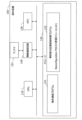
- FIG. 2 is a diagram showing a configuration example of the wireless communication system 10.
- FIG. 3 is a diagram showing a configuration example of the terminal device 100.
- FIG. 4 is a diagram illustrating a configuration example of the base station device 200.
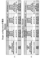
- FIG. 5 is a diagram showing an example of PDCCH in the case of Single configuration.
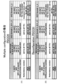
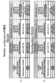
- FIG. 6 is a diagram showing an example of PDCCH in the case of multiple configuration.
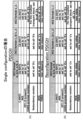
- FIG. 7 is a diagram showing an example of PDCCH in the case of Single configuration.
- FIG. 8 is a diagram showing an example of PDCCH in case of multiple configuration.
- FIG. 9 is a diagram illustrating an example of radio resources for use case 1.
- FIG. 10 is a diagram illustrating an example of radio resources for use case 1.
- FIG. 11 is a diagram illustrating an example of radio resources for use case 2.
- FIG. 12 is a diagram illustrating an example of radio resources for use case 2.
- the wireless communication system 3 is a wireless communication system that includes a first wireless communication device 1 and a second wireless communication device 2.
- the first wireless communication device and the second wireless communication device 2 communicate wirelessly.
- the first wireless communication device and the second wireless communication device 2 perform pre-allocation type communication in which data is transmitted and received using wireless resources set in advance.
- FIG. 1 is a diagram showing an example of wireless communication in the wireless communication system 3.
- FIG. 1A is a diagram illustrating an example of a sequence for transmitting data from the second wireless communication device 2 to the first wireless communication device 1.
- the second wireless communication device 2 transmits data to the first wireless communication device 1 using wireless resources allocated in advance (hereinafter sometimes referred to as advance wireless resources) (S1).
- the frequency of the advance radio resource is the first frequency.
- the first wireless communication device 1 transmits a control signal to the second wireless communication device 2 (S2).
- the control signal is a message instructing to change the frequency of the advance radio resource used by the second wireless communication device.
- the control signal includes information to change the frequency of the advance radio resource to the second frequency.
- the second wireless communication device 2 transmits data to the first wireless communication device 1 using the preliminary wireless resource of the second frequency when the preliminary wireless resource transmission period comes (S3).
- FIG. 1B is a diagram showing an example of radio resources.
- the horizontal axis of radio resources indicates time (transmission timing).
- the second wireless communication device 2 uses the advance wireless resources of the first frequency in slot 2 to transmit data (S1).
- the second wireless communication device 2 receives a control signal from the first wireless communication device 1 (S2).
- the control signal includes information to change the frequency of the advance radio resource to the second frequency.
- the second wireless communication device 2 transmits data to the first wireless communication device 1 using the pre-wireless resource of the second frequency (S3).
- FIG. 2 is a diagram showing a configuration example of the wireless communication system 10.
- the wireless communication system 10 includes a base station device 200 and a terminal device 100.
- the wireless communication system 10 is, for example, a wireless communication system that is installed within the system and supports IIOT.
- the terminal device 100 is a communication device attached to equipment (device) within the system.
- Base station device 200 is a communication device installed within the system.
- the base station device 200 is compatible with various communication generations (eg, 5G, Beyond 5G, etc.), for example. Further, the base station device 200 may be configured with one device, or may be configured with a plurality of devices such as a CU (Central Unit) and a DU (Distributed Unit).
- CU Central Unit
- DU Distributed Unit
- the terminal device 100 periodically transmits data to the base station device 200.
- the terminal device 100 uses CG radio resources in periodic (PDT) data transmission.
- the terminal device 100 also supports semi-regular (ADT) data transmission.
- Semi-regular data transmission includes, for example, data transmission delayed from regular data transmission timing.
- the terminal device 100 supports changing the frequency of CG resources.
- terminal device 100 there is one terminal device 100 in FIG. 2, there may be a plurality of terminal devices. Further, in the following embodiments, data transmission from the terminal device 100 to the base station device 200 will be explained as an example, but communication between the terminal devices 100 and data transmission from the base station device 200 to the terminal device 100 will also be described. Similar processing can be applied.
- FIG. 3 is a diagram showing a configuration example of the terminal device 100.
- the terminal device 100 includes a CPU (Central Processing Unit) 110, a storage 120, a memory 130, a wireless communication circuit 150, and an antenna 151.
- CPU Central Processing Unit
- the storage 120 is an auxiliary storage device such as a flash memory, an HDD (Hard Disk Drive), or an SSD (Solid State Drive) that stores programs and data.
- the storage 120 stores a terminal communication program 121 and a pre-assigned communication controlled program 122.
- the memory 130 is an area into which programs stored in the storage 120 are loaded.
- the memory 130 may also be used as an area for programs to store data.
- the wireless communication circuit 150 is a device that performs wireless communication with the base station device 200 and other terminal devices 100.
- the wireless communication circuit 150 includes an antenna 151.
- the antenna 151 includes, for example, a directional antenna that can control the direction of transmission and reception of radio waves.
- the CPU 110 is a processor that loads a program stored in the storage 120 into the memory 130, executes the loaded program, constructs each part, and implements each process.
- the CPU 110 executes the terminal communication program 121 to construct a second communication unit and perform terminal communication processing.
- the terminal communication process is a process of wirelessly communicating with the base station device 200 and other terminal devices 100.
- the CPU 110 executes the pre-allocation type communication controlled program 122 to construct the second control unit and performs the pre-allocated communication controlled processing.
- the pre-assigned communication controlled process is a process that controls the pre-assigned communication controlled process of the terminal device 100 in accordance with an instruction from the base station device 200.
- the terminal device 100 changes the frequency of the CG resource, for example, in the pre-allocation type communication controlled process.
- the terminal device 100 is instructed by the base station device 200 to change the frequency of the CG resource, and changes the frequency according to the instruction.
- the terminal device 100 executes the Reconfiguration PDCCH reception module 1221 included in the pre-assigned communication controlled program 122 to build a second control unit and perform Reconfiguration PDCCH reception processing.
- the Reconfiguration PDCCH reception process is a process of receiving the Reconfiguration PDCCH and changing the frequency of the CG resource. Reconfiguration PDCCH will be described later.
- FIG. 4 is a diagram illustrating a configuration example of the base station device 200.
- Base station device 200 includes CPU 210, storage 220, memory 230, wireless communication circuit 250, and antenna 251.
- the storage 220 is an auxiliary storage device such as a flash memory, HDD, or SSD that stores programs and data.
- the storage 220 stores a base station communication program 221 and a pre-allocation type communication control program 222.
- the memory 230 is an area into which programs stored in the storage 220 are loaded.
- the memory 230 may also be used as an area for programs to store data.
- the wireless communication circuit 250 is a device that performs wireless communication with the terminal device 100.
- the wireless communication circuit 250 includes an antenna 251.
- the antenna 251 includes, for example, a directional antenna that can control the direction of transmission and reception of radio waves.
- the CPU 210 is a processor that loads a program stored in the storage 220 into the memory 230, executes the loaded program, constructs each part, and implements each process.
- the CPU 210 executes the base station communication program 221 to build a communication unit and perform communication processing.
- the base station communication process is a process of performing wireless communication with the terminal device 100.
- the base station device 200 wirelessly connects with the terminal device 100, transmits data and control signals to the terminal device 100, and receives data from the terminal device 100.
- the CPU 210 executes the Reconfiguration PDCCH transmission module 2221 included in the pre-assigned communication control program 222 to build a control unit and perform Reconfiguration PDCCH transmission processing.
- the Reconfiguration PDCCH transmission process is a process of transmitting a Reconfiguration PDCCH including the changed frequency when changing the frequency of the CG resource of the terminal device 100.
- ⁇ CG type 1 Set the frequency and transmission cycle using RRC.
- the terminal device 100 starts a transmission cycle from the slot in which it receives RRC.
- ⁇ CG type 2 Set only the transmission cycle using RRC.
- the terminal device 100 starts a transmission cycle from the slot in which it receives an Activation PDCCH (Physical Downlink Control Channel) for setting the frequency.
- Activation PDCCH Physical Downlink Control Channel
- the terminal device 100 stops communication.
- ⁇ SPS Set the frequency and transmission cycle using RRC.
- the terminal device 100 starts a transmission cycle from the slot in which it receives the Activation PDCCH while receiving the configuration via RRC.
- the terminal device 100 stops communication. Furthermore, in each method, resetting of the transmission cycle is performed as follows.
- the terminal device 100 restarts the transmission cycle from the slot in which the RRC is received.
- the terminal device 100 restarts the transmission cycle from the slot in which the Reactivation PDCCH is received.
- the terminal device 100 restarts the transmission cycle from the slot in which the Reactivation PDCCH is received.
- the terminal device 100 flexibly changes the frequency and the transmission cycle (or maintains it). It may not be possible. Therefore, the wireless communication system 10 enables the use of Reconfiguration PDCCH.
- Reconfiguration PDCCH is an example of a control signal (reconfiguration control signal) that changes (reconfigures) the frequency of a CG resource.
- FIG. 5 is a diagram showing an example of PDCCH in the case of Single configuration.
- FIG. 5A shows a normal PDCCH
- FIG. 5B shows a Reconfiguration PDCCH.
- normal PDCCH refers to PDCCH other than Reconfiguration PDCCH.
- FIG. 5 shows an example of information elements (fields) of PDCCH.
- MCS Modulation and Coding Scheme
- the frequency of the CG resource to be changed is set in FDRA (Frequency Domain Resource Allocation).
- the terminal device 100 changes the frequency of subsequent CG resources to the frequency set in FDRA.
- FIG. 6 is a diagram showing an example of PDCCH in the case of multiple configuration.
- 6A is a normal PDCCH
- FIG. 6B is a Reconfiguration PDCCH.
- 0 is set in the MCS.
- the frequency of the CG resource to be changed to FDRA is set.
- the terminal device 100 changes the frequency of subsequent CG resources to the frequency set in FDRA.
- FIG. 7 is a diagram showing an example of PDCCH in the case of Single configuration.
- FIG. 7A shows a normal PDCCH
- FIG. 7B shows a Reconfiguration PDCCH.
- a new MCS value is set in the MCS.
- the frequency of the CG resource to be changed is set in the FDRA.
- the terminal device 100 changes the frequency of subsequent CG resources to the frequency set in FDRA.
- FIG. 8 is a diagram showing an example of PDCCH in the case of multiple configuration.
- FIG. 8A shows a normal PDCCH
- FIG. 8B shows a Reconfiguration PDCCH.
- a new MCS value is set in the MCS.
- the frequency of the CG resource to be changed is set in the FDRA.
- the terminal device 100 changes the frequency of subsequent CG resources to the frequency set in FDRA.
- FIG. 9 is a diagram illustrating an example of radio resources for use case 1.
- Use case 1 is a case in which transmission of CG resources is started in slot 2 and the transmission cycle is maintained at 5 slots.
- “RF ON” and “RF OFF” at the bottom of the figure indicate ON and OFF of the RF section of the terminal device 100.
- the radio resource indicates frequency (f) in the vertical direction and time (t) in the horizontal direction.
- the K2 value in FIG. 1 is 1. The K2 value indicates the slot length from when the PDCCH is received until the start of the transmission cycle is applied.
- the terminal device 100 receives the Activation PDCCH in slot 1 (S10).
- the terminal device 100 monitors the PDCCH for retransmission for a predetermined period because retransmission of the CG resource may occur (S11).
- the terminal device 100 After monitoring for a predetermined period, the terminal device 100 turns off the RF section in slot 5 (S12).
- Reactivation PDCCH includes frequency information to be changed.
- the terminal device 100 uses the CG resource of the changed frequency (slot 7) and monitors the retransmission PDCCH for a predetermined period (S14).
- FIG. 10 is a diagram showing an example of radio resources for use case 1.
- Reconfiguration PDCCH is used to change the frequency of the CG resource.
- the terminal device 100 turns on the RF unit in slot 2 and starts transmitting CG resources (S20). Note that in FIG. 10, since the terminal device 100 does not assume a frequency change by receiving the Activation PDCCH and the Reactivation PDCCH, the RF section can be turned off until the timing of transmitting the CG resource.
- the terminal device 100 monitors the PDCCH for retransmission for a predetermined period because retransmission of the CG resource may occur (S21).
- the terminal device 100 monitors the Reconfiguration PDCCH. Then, the terminal device 100 receives the Reconfiguration PDCCH in slot 4 and turns off the RF section (S22).
- the terminal device 100 turns on the RF section in slot 7 (S23), uses the CG resource of the changed frequency, and monitors the retransmission PDCCH for a predetermined period (S24).
- the terminal device 100 does not use the reception of the Reconfiguration PDCCH as a trigger for changing the transmission cycle of the CG resource. Therefore, the Reconfiguration PDCCH can maintain the transmission cycle of CG resources while changing the frequency.
- the terminal device 100 can realize power saving by receiving the Reconfiguration PDCCH while monitoring the PDCCH for retransmission.
- the RF section can be turned off in slots 1 and 6, the power consumption of the terminal device 100 is reduced compared to FIG. 9.
- FIG. 11 is a diagram showing an example of radio resources for use case 2.
- Use case 2 is an example in which the frequency of the CG resource is changed and transmitted when data retransmission occurs.
- Reconfiguration PDCCH is used to change the frequency of the CG resource.
- the terminal device 100 transmits data using the CG resource of slot 2. Then, the terminal device 100 receives, for example, a retransmission PDCCH for which data transmission using the CG resource has failed and retransmission is requested (S30).
- the terminal device 100 retransmits data using a resource (retransmission PUSCH: Physical Uplink Shared Channel) whose frequency has been changed from the CG resource (S31).
- a resource retransmission PUSCH: Physical Uplink Shared Channel
- the terminal device 100 receives a Reconfiguration PDCCH that changes the frequency of the CG resource to the frequency used for retransmission (S32).
- the terminal device 100 uses the changed frequency (the frequency used for retransmission) as the frequency of the CG resource and transmits data (S33). Thereafter, CG resources are transmitted at the changed frequency.
- FIG. 12 is a diagram showing an example of radio resources for use case 2.
- the frequency of the CG resource is not changed in Reconfiguration PDCCH, and the frequency used at the time of retransmission is continued to be used.
- the terminal device 100 transmits data using the CG resource of slot 2. Then, the terminal device 100 receives, for example, a retransmission PDCCH for which data transmission using the CG resource has failed and retransmission is requested (S40).
- the terminal device 100 retransmits the data using a resource (retransmission PUSCH) whose frequency has been changed from the CG resource (S41).
- the terminal device 100 sets the frequency used for retransmission as the frequency of the CG resource and transmits data (S42). Thereafter, the CG resource is transmitted on the frequency used for retransmission.
- the expiration date indicates, for example, how long the changed frequency resource is valid. For example, it may be set whether or not the changed frequency resource is changed only once (from the second time onwards, the frequency resource before the change is used). Further, for example, it may be set that the changed frequency resource is changed only N times (N is an integer of 1 or more). Furthermore, for example, the changed frequency resource may be set to have no expiration date and to be valid thereafter.
- the requirements described in the first embodiment, second embodiment, and other embodiments may be combined. Further, the requirements described in the first embodiment, the second embodiment, and other embodiments may be used depending on, for example, wireless conditions, system requirements, etc.
- the shift amount (width) described in the first embodiment, the second embodiment, and other embodiments is similar to the shift amount (width) described in the first embodiment, the second embodiment, and other embodiments. , frame).
- Wireless communication system 10 Wireless communication system 100: Terminal device 110: CPU 120: Storage 121: Terminal communication program 122: Pre-allocated communication controlled program 1221: PDCCH reception module 130: Memory 150: Wireless communication circuit 151: Antenna 200: Base station device 210: CPU 220: Storage 221: Base station communication program 222: Pre-assigned communication control program 2221: PDCCH transmission module 230: Memory 250: Wireless communication circuit 251: Antenna
Landscapes
- Engineering & Computer Science (AREA)
- Computer Networks & Wireless Communication (AREA)
- Signal Processing (AREA)
- Mobile Radio Communication Systems (AREA)
Priority Applications (3)
| Application Number | Priority Date | Filing Date | Title |
|---|---|---|---|
| JP2024508861A JPWO2023181137A1 (https=) | 2022-03-22 | 2022-03-22 | |
| PCT/JP2022/013318 WO2023181137A1 (ja) | 2022-03-22 | 2022-03-22 | 第1無線通信装置及び第2無線通信装置 |
| US18/884,257 US20250024443A1 (en) | 2022-03-22 | 2024-09-13 | First wireless communication device and second wireless communication device |
Applications Claiming Priority (1)
| Application Number | Priority Date | Filing Date | Title |
|---|---|---|---|
| PCT/JP2022/013318 WO2023181137A1 (ja) | 2022-03-22 | 2022-03-22 | 第1無線通信装置及び第2無線通信装置 |
Related Child Applications (1)
| Application Number | Title | Priority Date | Filing Date |
|---|---|---|---|
| US18/884,257 Continuation US20250024443A1 (en) | 2022-03-22 | 2024-09-13 | First wireless communication device and second wireless communication device |
Publications (1)
| Publication Number | Publication Date |
|---|---|
| WO2023181137A1 true WO2023181137A1 (ja) | 2023-09-28 |
Family
ID=88100235
Family Applications (1)
| Application Number | Title | Priority Date | Filing Date |
|---|---|---|---|
| PCT/JP2022/013318 Ceased WO2023181137A1 (ja) | 2022-03-22 | 2022-03-22 | 第1無線通信装置及び第2無線通信装置 |
Country Status (3)
| Country | Link |
|---|---|
| US (1) | US20250024443A1 (https=) |
| JP (1) | JPWO2023181137A1 (https=) |
| WO (1) | WO2023181137A1 (https=) |
Citations (3)
| Publication number | Priority date | Publication date | Assignee | Title |
|---|---|---|---|---|
| WO2019031267A1 (ja) * | 2017-08-09 | 2019-02-14 | ソニー株式会社 | 通信装置および方法 |
| WO2021215098A1 (ja) * | 2020-04-24 | 2021-10-28 | パナソニック インテレクチュアル プロパティ コーポレーション オブ アメリカ | 端末及び通信方法 |
| JP2021534628A (ja) * | 2018-08-09 | 2021-12-09 | コンヴィーダ ワイヤレス, エルエルシー | 構成済みグラントを使用したul送信のためのuci設計 |
Family Cites Families (1)
| Publication number | Priority date | Publication date | Assignee | Title |
|---|---|---|---|---|
| JP6203285B2 (ja) * | 2013-12-10 | 2017-09-27 | 株式会社東芝 | 無線装置および無線通信方法 |
-
2022
- 2022-03-22 JP JP2024508861A patent/JPWO2023181137A1/ja active Pending
- 2022-03-22 WO PCT/JP2022/013318 patent/WO2023181137A1/ja not_active Ceased
-
2024
- 2024-09-13 US US18/884,257 patent/US20250024443A1/en active Pending
Patent Citations (3)
| Publication number | Priority date | Publication date | Assignee | Title |
|---|---|---|---|---|
| WO2019031267A1 (ja) * | 2017-08-09 | 2019-02-14 | ソニー株式会社 | 通信装置および方法 |
| JP2021534628A (ja) * | 2018-08-09 | 2021-12-09 | コンヴィーダ ワイヤレス, エルエルシー | 構成済みグラントを使用したul送信のためのuci設計 |
| WO2021215098A1 (ja) * | 2020-04-24 | 2021-10-28 | パナソニック インテレクチュアル プロパティ コーポレーション オブ アメリカ | 端末及び通信方法 |
Also Published As
| Publication number | Publication date |
|---|---|
| JPWO2023181137A1 (https=) | 2023-09-28 |
| US20250024443A1 (en) | 2025-01-16 |
Similar Documents
| Publication | Publication Date | Title |
|---|---|---|
| US11737111B2 (en) | Method and apparatus for communicating user data via a physical shared channel | |
| KR102376053B1 (ko) | 불연속 수신 통신 방법과 통신 장치, 통신 디바이스 및 통신 시스템 | |
| TW202325058A (zh) | 藉由基地台進行的方法 | |
| CN113992311B (zh) | 用户设备装置和基站装置 | |
| US11026203B2 (en) | Methods, devices, and systems for initial grant-free transmission determination | |
| CN113785622A (zh) | 用于传送具有偏移的数据通信的方法和装置 | |
| CN113906791B (zh) | 收发器设备和调度设备 | |
| JP7327483B2 (ja) | マルチtrp送信のための方法、デバイス、及びプログラム | |
| JP2019507968A (ja) | サービス伝送のための方法、移動局及びネットワークデバイス | |
| KR20240016899A (ko) | 다중 trp 전송을 위한 tci 프레임워크 | |
| KR20150111800A (ko) | 무선 통신 시스템에서 시간 분할 복신 및 주파수 복신 반송파 집성을 위한 장치 및 방법 | |
| US20250024432A1 (en) | First wireless communication device and second wireless communication device | |
| JP2024019100A (ja) | マルチtrp送信のためのtciフレームワーク | |
| JP2022540974A (ja) | 通信方法、通信デバイス及びコンピュータプログラム | |
| US12574900B2 (en) | Spectrum efficiency in configured grant | |
| CN114208077A (zh) | 用于配置授权上行链路传输的重传机制 | |
| WO2023181137A1 (ja) | 第1無線通信装置及び第2無線通信装置 | |
| EP4336931A1 (en) | Communication device, base station, and communication method | |
| JP6816808B2 (ja) | 無線端末、無線基地局および無線システム | |
| WO2023152992A1 (ja) | 第1無線通信装置及び第2無線通信装置 | |
| JP7791457B2 (ja) | 第1無線通信装置、第2無線通信装置、無線通信システム、及び無線通信方法 | |
| CN113825150B (zh) | 一种用于多trp传输的计时器操作方法和设备 | |
| WO2024166316A1 (ja) | 基地局装置、端末装置、及び無線通信システム | |
| WO2025069301A1 (ja) | 端末、基地局、及び無線通信システム | |
| CN116896403A (zh) | 用于中继器中波束管理的信息共享 |
Legal Events
| Date | Code | Title | Description |
|---|---|---|---|
| 121 | Ep: the epo has been informed by wipo that ep was designated in this application |
Ref document number: 22933283 Country of ref document: EP Kind code of ref document: A1 |
|
| ENP | Entry into the national phase |
Ref document number: 2024508861 Country of ref document: JP Kind code of ref document: A |
|
| NENP | Non-entry into the national phase |
Ref country code: DE |
|
| 122 | Ep: pct application non-entry in european phase |
Ref document number: 22933283 Country of ref document: EP Kind code of ref document: A1 |