WO2023176921A1 - 尿素製造方法及び尿素製造装置 - Google Patents
尿素製造方法及び尿素製造装置 Download PDFInfo
- Publication number
- WO2023176921A1 WO2023176921A1 PCT/JP2023/010278 JP2023010278W WO2023176921A1 WO 2023176921 A1 WO2023176921 A1 WO 2023176921A1 JP 2023010278 W JP2023010278 W JP 2023010278W WO 2023176921 A1 WO2023176921 A1 WO 2023176921A1
- Authority
- WO
- WIPO (PCT)
- Prior art keywords
- unit
- combustion
- urea
- produced
- power generation
- Prior art date
- Legal status (The legal status is an assumption and is not a legal conclusion. Google has not performed a legal analysis and makes no representation as to the accuracy of the status listed.)
- Ceased
Links
Images



Classifications
-
- C—CHEMISTRY; METALLURGY
- C01—INORGANIC CHEMISTRY
- C01C—AMMONIA; CYANOGEN; COMPOUNDS THEREOF
- C01C1/00—Ammonia; Compounds thereof
- C01C1/02—Preparation, purification or separation of ammonia
- C01C1/04—Preparation of ammonia by synthesis
-
- C—CHEMISTRY; METALLURGY
- C07—ORGANIC CHEMISTRY
- C07C—ACYCLIC OR CARBOCYCLIC COMPOUNDS
- C07C273/00—Preparation of urea or its derivatives, i.e. compounds containing any of the groups, the nitrogen atoms not being part of nitro or nitroso groups
- C07C273/02—Preparation of urea or its derivatives, i.e. compounds containing any of the groups, the nitrogen atoms not being part of nitro or nitroso groups of urea, its salts, complexes or addition compounds
- C07C273/10—Preparation of urea or its derivatives, i.e. compounds containing any of the groups, the nitrogen atoms not being part of nitro or nitroso groups of urea, its salts, complexes or addition compounds combined with the synthesis of ammonia
-
- C—CHEMISTRY; METALLURGY
- C01—INORGANIC CHEMISTRY
- C01C—AMMONIA; CYANOGEN; COMPOUNDS THEREOF
- C01C1/00—Ammonia; Compounds thereof
- C01C1/02—Preparation, purification or separation of ammonia
- C01C1/04—Preparation of ammonia by synthesis
- C01C1/0405—Preparation of ammonia by synthesis from N2 and H2 in presence of a catalyst
- C01C1/0488—Processes integrated with preparations of other compounds, e.g. methanol, urea or with processes for power generation
-
- C—CHEMISTRY; METALLURGY
- C07—ORGANIC CHEMISTRY
- C07C—ACYCLIC OR CARBOCYCLIC COMPOUNDS
- C07C273/00—Preparation of urea or its derivatives, i.e. compounds containing any of the groups, the nitrogen atoms not being part of nitro or nitroso groups
- C07C273/02—Preparation of urea or its derivatives, i.e. compounds containing any of the groups, the nitrogen atoms not being part of nitro or nitroso groups of urea, its salts, complexes or addition compounds
- C07C273/04—Preparation of urea or its derivatives, i.e. compounds containing any of the groups, the nitrogen atoms not being part of nitro or nitroso groups of urea, its salts, complexes or addition compounds from carbon dioxide and ammonia
-
- C—CHEMISTRY; METALLURGY
- C07—ORGANIC CHEMISTRY
- C07C—ACYCLIC OR CARBOCYCLIC COMPOUNDS
- C07C275/00—Derivatives of urea, i.e. compounds containing any of the groups, the nitrogen atoms not being part of nitro or nitroso groups
-
- C—CHEMISTRY; METALLURGY
- C25—ELECTROLYTIC OR ELECTROPHORETIC PROCESSES; APPARATUS THEREFOR
- C25B—ELECTROLYTIC OR ELECTROPHORETIC PROCESSES FOR THE PRODUCTION OF COMPOUNDS OR NON-METALS; APPARATUS THEREFOR
- C25B1/00—Electrolytic production of inorganic compounds or non-metals
- C25B1/01—Products
- C25B1/02—Hydrogen or oxygen
- C25B1/04—Hydrogen or oxygen by electrolysis of water
-
- C—CHEMISTRY; METALLURGY
- C25—ELECTROLYTIC OR ELECTROPHORETIC PROCESSES; APPARATUS THEREFOR
- C25B—ELECTROLYTIC OR ELECTROPHORETIC PROCESSES FOR THE PRODUCTION OF COMPOUNDS OR NON-METALS; APPARATUS THEREFOR
- C25B15/00—Operating or servicing cells
- C25B15/08—Supplying or removing reactants or electrolytes; Regeneration of electrolytes
- C25B15/081—Supplying products to non-electrochemical reactors that are combined with the electrochemical cell, e.g. Sabatier reactor
-
- C—CHEMISTRY; METALLURGY
- C25—ELECTROLYTIC OR ELECTROPHORETIC PROCESSES; APPARATUS THEREFOR
- C25B—ELECTROLYTIC OR ELECTROPHORETIC PROCESSES FOR THE PRODUCTION OF COMPOUNDS OR NON-METALS; APPARATUS THEREFOR
- C25B9/00—Cells or assemblies of cells; Constructional parts of cells; Assemblies of constructional parts, e.g. electrode-diaphragm assemblies; Process-related cell features
Definitions
- the present invention relates to a urea production method and a urea production apparatus for producing urea, and more specifically to a urea production method in which oxygen produced by electrolysis of water is supplied to a combustion apparatus and carbon dioxide, which is the combustion exhaust gas, is used as a raw material. and urea production equipment.
- ammonia and carbon dioxide are required as raw materials.
- ammonia can be synthesized from nitrogen and hydrogen.
- Carbon dioxide can also be obtained, for example, by burning fuel.
- Patent Document 1 describes a method of separating and recovering nitrogen from air and reacting this nitrogen with hydrogen to synthesize ammonia. Another method is to use gas after nitrogen has been separated, that is, gas containing high concentration of oxygen, to burn fuel to produce carbon dioxide, and to use this carbon dioxide and ammonia as raw materials to produce urea.
- gas after nitrogen has been separated that is, gas containing high concentration of oxygen
- to burn fuel to produce carbon dioxide and to use this carbon dioxide and ammonia as raw materials to produce urea.
- Patent Document 1 is a method whose main purpose is simply to improve an oxyfuel combustion system that involves synthesis of ammonia, and is not a method whose main purpose is simply to produce urea.
- urea is produced using ammonia and carbon dioxide as raw materials as described in Patent Document 1
- the amount of carbon dioxide produced is small, so the surplus amount of ammonia becomes very large. Therefore, the method described in Patent Document 1 does not necessarily have a sufficient material balance for producing urea.
- an object of the present invention is to provide a urea production method and a urea production apparatus with improved material balance.
- the inventor of the present invention found that it is extremely possible to use oxygen obtained by electrolysis of water in the oxy-combustion process and to produce urea using the carbon dioxide obtained in this process as a raw material.
- the present invention has been completed based on the discovery that the present invention is effective.
- the present invention includes an electrolysis process for producing hydrogen and oxygen by electrolysis of water; an air separation process that separates and recovers nitrogen from air; an ammonia synthesis step of synthesizing ammonia using as raw materials at least a portion of the hydrogen produced in the electrolysis step and at least a portion of the nitrogen separated and recovered in the air separation step; an oxy-combustion step in which at least part of the oxygen produced in the electrolysis step is used to combust fuel to produce carbon dioxide;
- the urea production method includes a urea synthesis step of synthesizing urea using at least a portion of the carbon dioxide produced in the oxy-combustion step and at least a portion of the ammonia produced in the ammonia synthesis step as raw materials.
- the present invention includes an electrolysis unit (E) that produces hydrogen and oxygen by electrolysis of water; an air separation unit (A) that separates and recovers nitrogen from air; an ammonia synthesis unit (N) that synthesizes ammonia using as raw materials at least part of the hydrogen produced in the electrolysis unit (E) and at least part of the nitrogen separated and recovered in the air separation unit (A); and, an oxyfuel combustion unit (O) that uses at least a portion of the oxygen produced in the electrolysis unit (E) to combust fuel and produce carbon dioxide; A urea synthesis unit (U) that synthesizes urea using as raw materials at least part of the carbon dioxide produced in the oxyfuel combustion unit (O) and at least part of the ammonia produced in the ammonia synthesis unit (N).
- This is a urea production apparatus having the following.
- oxygen obtained by electrolysis of water is used in the oxy-combustion process, and urea is produced using the carbon dioxide obtained in this process as a raw material, so the amount of oxygen that can be used in the oxy-combustion process is significantly increased. do. As a result, the surplus amount of ammonia is reduced and the material balance for producing urea is improved.
- the amount of oxygen that can be used in the oxy-combustion process is significantly increased, so the amount of heat obtained in the oxy-combustion process increases, the amount of steam produced increases, and the amount of steam required by the urea synthesis process increases. can be fully covered. Furthermore, excess steam can be used, for example, as a heat source or for power generation.
- the oxygen obtained through the air separation process which is used in the normal oxygen combustion process, contains small amounts of nitrogen and argon. If only this small amount of oxygen containing nitrogen and argon is used in the oxy-combustion process, the purity of the carbon dioxide obtained through the oxy-combustion process will decrease. As a result, when the obtained carbon dioxide is used for urea synthesis, a carbon dioxide purification step may be necessary.
- oxygen obtained by electrolysis of water is used in the oxygen combustion process, and since the oxygen contains almost no nitrogen or argon, the need for a carbon dioxide purification process is reduced, and the process can also be simplified.
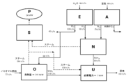
- FIG. 2 is a process flow diagram of a urea production apparatus using the urea production method of the present invention.
- 3 is a process flow diagram of Example 1.
- FIG. 3 is a process flow diagram of Example 2.
- FIG. 3 is a process flow diagram of Example 3.
- 3 is a process flow diagram of Comparative Example 1.
- the method described in Patent Document 1 that is, the oxygen used in the oxyfuel combustion process is only the oxygen obtained in the air separation process, and in the method of the present invention, which does not include the electrolysis process, surplus ammonia is used.
- the amount increases.
- biomass fuel represented by cellulose C 6 H 10 O 5
- the reaction formula is as shown in Formula 1 below.
- Equation 1 the ratio of each component was determined based on 1 equivalent of nitrogen (N 2 ).
- H 2 hydrogen
- N 2 nitrogen
- Equation 1 generation system
- biomass fuel cellulose C 6 H 10 O 5
- CO 2 carbon dioxide
- the equivalent ratio of both (NH 3 /CO 2 ) is 8.
- Equation 3 the ratio of each component was determined based on 1 equivalent of nitrogen (N 2 ).
- N 2 1 equivalent of nitrogen
- H 2 hydrogen
- O 2 oxygen
- based on the production ratio (H 2 :O 2 2:1) when water (H 2 O) is electrolyzed, it is generated when obtaining 3 equivalents of hydrogen (H 2 ).
- the equivalent ratio of oxygen (O 2 ) "3/2" was adopted as the ratio.
- Equation 3 generation system
- biomass fuel cellulose C 6 H 10 O 5
- 3/2 equivalent of oxygen is obtained from the electrolysis process
- the oxyfuel combustion process 1 equivalent of carbon dioxide (CO 2 ) is obtained in the ammonia synthesis step
- 2 equivalents of ammonia are obtained in the ammonia synthesis step. Therefore, the equivalent ratio of both (NH 3 /CO 2 ) is 2.
- the theoretical equivalent for urea synthesis is 2 as mentioned above. Therefore, in this case, in the method of the present invention, there is no shortage of carbon dioxide and no surplus ammonia is generated.
- Equation 4 The equivalent ratios of nitrogen (N 2 ), hydrogen (H 2 ), and oxygen (O 2 ) on the left side (raw material system) of Equation 4 are the same as in Equation 3.
- Equation 4 generation system
- fossil fuel methane CH 4
- 3/2 equivalent of oxygen is obtained from the electrolysis process
- 3/4 equivalent is obtained from the oxyfuel combustion process.
- the theoretical equivalent for urea synthesis is 2 as mentioned above. Therefore, in the method of the present invention in this case, there is a slight shortage of carbon dioxide and a slight surplus of ammonia is generated.
- FIG. 1 is a process flow diagram of a urea production apparatus using the urea production method of the present invention. Each process and each unit will be explained below.
- the electrolysis unit (E) shown in FIG. 1 is a unit that performs an electrolysis process to produce hydrogen and oxygen by electrolyzing water.
- the specific electrolysis conditions and the configuration of the electrolysis unit (E) in this electrolysis step known conditions and configurations related to water electrolysis technology can be adopted without restriction.
- water is supplied to the electrolysis unit (E). Hydrogen and oxygen are then produced by electrolyzing this water. At least a portion of the obtained hydrogen is supplied to an ammonia synthesis unit (N) described later and used as a raw material for synthesizing ammonia. On the other hand, at least a portion of the obtained oxygen is supplied to an oxyfuel combustion unit (O) to be described later, and used as a raw material for producing carbon dioxide.
- E electrolysis unit
- O oxyfuel combustion unit
- Electricity is required to perform the electrolysis process.
- the type of power used is not particularly limited. However, from the viewpoint of environmental protection, it is preferable to use electricity generated by renewable energy.
- Renewable energy is energy that always exists in nature, such as biomass fuel, solar power, wind power, geothermal power, and hydropower.
- generating electricity using the heat of combustion of biomass fuel is advantageous in that it is carbon neutral.
- solar power, wind power, geothermal power, or hydropower it is advantageous in that no carbon dioxide is emitted during power generation.
- biomass fuel is used as a fuel in the oxyfuel combustion unit (O) described later, power is generated using the combustion heat, and at least a part of the obtained power is used as power for the electrolysis process. It is also possible to do so.
- the air separation unit (A) shown in FIG. 1 is a unit that performs an air separation process of separating and recovering nitrogen from air. Furthermore, this air separation step may be a step of separating and recovering nitrogen from air and producing a gas containing a high concentration of oxygen.
- this air separation step may be a step of separating and recovering nitrogen from air and producing a gas containing a high concentration of oxygen.
- known conditions and configurations related to air separation technology can be adopted without restriction. Specific examples thereof include cryogenic separation method and pressure swing absorption technology (PSA).
- air is supplied to the air separation unit (A). Nitrogen is then separated and recovered from this air to produce a gas containing a high concentration of oxygen (the oxygen concentration in the gas is usually 90% to 100% by volume, hereinafter referred to as "highly concentrated oxygen"). At least a portion of the separated and recovered nitrogen is supplied to an ammonia synthesis unit (N) to be described later, and used as a raw material for synthesizing ammonia. On the other hand, at least a portion of the obtained highly concentrated oxygen is supplied to an oxyfuel combustion unit (O) described later and used as a raw material for producing carbon dioxide.
- an oxyfuel combustion unit (O) described later and used as a raw material for producing carbon dioxide.
- the high concentration oxygen produced in the air separation unit (A) is supplied to the oxyfuel combustion unit (O), but the present invention is not limited to this.
- the required amount of carbon dioxide can be sufficiently produced by supplying only the oxygen produced in the electrolysis unit (E) to the oxyfuel combustion unit (O)
- the high concentration oxygen produced in the air separation unit (A) For example, it may be collected outside the system without being supplied to the oxyfuel combustion unit (O).
- the configuration of the air separation unit (A) may be simplified by adopting a configuration in which nitrogen is separated and recovered from air but high concentration oxygen is not particularly produced.
- ammonia synthesis unit (N) The ammonia synthesis unit (N) shown in Figure 1 is an ammonia synthesis unit that synthesizes ammonia using at least part of the hydrogen produced in the electrolysis process and at least part of the nitrogen separated and recovered in the air separation process as raw materials. It is a unit that performs a process. Regarding the specific synthesis conditions and the configuration of the ammonia synthesis unit (N) in this ammonia synthesis step, known conditions and configurations related to ammonia synthesis technology can be employed without restriction. Specific examples thereof include the Haber method and other industrial ammonia synthesis methods.
- the ammonia synthesis unit (N) is supplied with hydrogen from the electrolysis unit (E) and nitrogen from the air separation unit (A). Then, ammonia is synthesized using this hydrogen and nitrogen as raw materials. At least a portion of the obtained ammonia is supplied to the urea synthesis unit (U) described later and used as a raw material for producing urea.
- the oxy-combustion unit (O) shown in FIG. 1 is a unit that performs an oxy-combustion process in which at least part of the oxygen produced in the electrolysis process is used to combust fuel to produce carbon dioxide.
- the specific combustion conditions in this oxy-combustion step and the configuration of the oxy-combustion unit (O) known conditions and configurations related to carbon dioxide production technology through combustion can be adopted without restriction.
- the embodiment shown in FIG. 1 is an embodiment in which carbon dioxide is produced by burning fuel using at least part of the oxygen produced in the electrolysis process and at least part of the highly concentrated oxygen produced in the air separation process. be.
- Such an embodiment is a particularly preferred embodiment when the amount of oxygen produced in the electrolysis process alone is insufficient, such as in the case described above using Equation 4 (when fossil fuel is used).
- the present invention is not limited to this embodiment. For example, in the case explained earlier using Equation 3 (when biomass fuel is used), if the supply of oxygen produced in the electrolysis process is sufficient, the high concentration from the air separation unit (A) There is no need to supply oxygen.
- the oxyfuel combustion unit (O) is supplied with oxygen from the electrolysis unit (E) and highly concentrated oxygen from the air separation unit (A). This oxygen and highly concentrated oxygen are then used to combust fuel and produce carbon dioxide. At least a portion of the obtained carbon dioxide is supplied to a urea synthesis unit (U) described later and used as a raw material for producing urea.
- the type of fuel used in the oxyfuel combustion process is not particularly limited. Specific examples thereof include biomass fuels such as wood pellets, organic wastes such as municipal garbage, and fossil fuels such as natural gas, oil, and coal. In particular, biomass fuel is preferable because it is carbon neutral compared to fossil fuels.
- the urea synthesis unit (U) shown in Fig. 1 is a urea synthesis unit that synthesizes urea using at least a part of carbon dioxide produced in an oxy-combustion process and at least a part of ammonia produced in an ammonia synthesis process as raw materials. It is a unit that performs a process. Regarding the specific synthesis conditions and configuration of the urea synthesis unit (U) in this urea synthesis step, known conditions and configurations related to urea synthesis technology can be employed without restriction.
- the urea synthesis unit (U) is supplied with carbon dioxide from the oxyfuel combustion unit (O) and ammonia from the ammonia synthesis unit (N). Urea is then synthesized using this carbon dioxide and ammonia as raw materials.
- the power generation unit (S) is a power generation unit that performs a power generation process of generating electricity using at least a portion of the thermal energy generated by combustion in the oxyfuel combustion process, and/or a power generation unit that performs a power generation process that uses at least a portion of the thermal energy generated by combustion in the oxyfuel combustion process, and/or a power generation unit that performs a power generation process that uses at least a portion of the thermal energy generated by combustion in the oxyfuel combustion process.
- This is a power generation unit that performs a power generation process of generating power using at least a part of the steam produced using a part of the steam.
- known conditions and configurations related to power generation technology can be adopted without restriction.
- the power generation unit (S) is a power generation unit that performs a steam turbine power generation process that generates power using steam.
- steam is supplied to the power generation unit (S) from an oxyfuel combustion unit (O) and an ammonia synthesis unit (N). This steam is then used to generate electricity through a turbine.
- the obtained electric power (P) can also be used, for example, in one or more processes selected from the group consisting of a urea synthesis process, an ammonia synthesis process, and an electrolysis process.
- An embodiment having a steam turbine power generation unit as the power generation unit (S) as shown in FIG. 1 is a preferred embodiment of the present invention.
- the steam comprises steam produced using at least a portion of the heat generated by combustion in the oxy-combustion unit (O). Since a relatively large amount of oxygen is supplied to the oxyfuel combustion unit (O) shown in FIG. 1, the amount of heat generated by combustion is also large. As a result, even if steam is supplied to the urea synthesis unit (U), the surplus steam can be used for power generation.
- the steam is not only steam produced using at least a part of the heat generated by combustion in the oxyfuel combustion unit (O), but also a reaction for ammonia synthesis in the ammonia synthesis unit (N). It also includes steam produced using at least a portion of the heat (for example, steam produced using heat exchange equipment that cools and condenses synthesized ammonia gas). Therefore, the amount of power generated will further increase.
- the present invention may include other equipment in addition to the units described above.
- other equipment include heat exchange equipment that produces steam using combustion heat, and carbon dioxide purification equipment (for example, equipment for dehydration and impurity removal).
- the present invention is not limited to the embodiment shown in FIG. 1 described above.
- a steam turbine power generation unit was used as the power generation unit (S).
- other power generation units may be added to this, or the steam turbine power generation unit may be replaced with other power generation units.
- the other power generation unit is, for example, a unit that performs a power generation process in which at least part of the thermal energy generated by combustion in the oxyfuel combustion process is directly used to generate electricity.
- Specific examples thereof include a unit that performs a gas turbine power generation process and a unit that performs a supercritical CO 2 cycle power generation process.
- Example 1 ( Figure 2)>
- E 16 t/h of hydrogen and 128 t/h of oxygen were produced from 144 t/h of water by electrolysis.
- air separation unit (A) 75 t/h of nitrogen was separated and recovered from 99 t/h of air.
- 91 t/h of ammonia was synthesized in the ammonia synthesis unit (N).
- the heat of combustion of the biomass was 2,873 kcal/kg, and the calorific value in the oxyfuel combustion unit (O) was approximately 241 MW.
- This heat was recovered to produce 264 t/h of steam.
- 139 t/h of steam was supplied to the urea synthesis unit (U) and used.
- the remaining steam was supplied to the steam turbine power generation unit (S).
- steam produced by recovering the reaction heat generated in the ammonia synthesis unit (N) was also supplied to the steam turbine power generation unit (S). Then, this steam was used to generate electricity, and 24 MW of electricity was obtained. A part of this electric power was supplied to the urea synthesis unit (U) to cover the required electric power of 7 MW.
- Example 2 ( Figure 3)>
- E 16 t/h of hydrogen and 128 t/h of oxygen were produced from 144 t/h of water by electrolysis.
- air separation unit (A) 75 t/h of nitrogen was separated and recovered from 99 t/h of air, producing 23 t/h of gas containing high concentration oxygen (oxygen concentration of approximately 98%).
- 91 t/h of ammonia was synthesized in the ammonia synthesis unit (N).
- the 104 t/h of carbon dioxide obtained as above and 80 t/h of the 91 t/h of ammonia produced in the ammonia synthesis unit (N) are supplied to the urea synthesis unit (U), producing 142 t/h of urea. did. Note that the remaining ammonia (11 t/h) was recovered outside the system.
- the heat of combustion of natural gas was 11,950 kcal/kg, and the calorific value in the oxyfuel combustion unit (O) was approximately 529 MW. This heat was recovered to produce 580 t/h of steam. Of this 580 t/h of steam, 123 t/h of steam was supplied to the urea synthesis unit (U) and used. The remaining steam was supplied to the steam turbine power generation unit (S). Furthermore, steam produced by recovering the reaction heat generated in the ammonia synthesis unit (N) was also supplied to the steam turbine power generation unit (S). The steam was then used to generate electricity, yielding 86 MW of electricity. A part of this electric power was supplied to the urea synthesis unit (U) to cover the required electric power of 6 MW.
- the heat of combustion of natural gas was 11,950 kcal/kg, and the calorific value in the oxyfuel combustion unit (O) was approximately 594 MW. This heat was recovered to produce 652 t/h of steam. Of this 652 t/h of steam, 139 t/h of steam was supplied to the urea synthesis unit (U) and used. The remaining steam was supplied to the steam turbine power generation unit (S). Furthermore, steam produced by recovering the reaction heat generated in the ammonia synthesis unit (N) was also supplied to the steam turbine power generation unit (S). The steam was then used to generate electricity, yielding 97MW of electricity. A part of this electric power was supplied to the urea synthesis unit (U) to cover the required electric power of 7 MW.
- the heat of combustion of natural gas was 11,950 kcal/kg, and the calorific value in the oxyfuel combustion unit (O) was approximately 83 MW. This heat was recovered to produce 91 t/h of steam. Of this 91 t/h of steam, 19 t/h of steam was supplied to the urea synthesis unit (U) and used. The remaining steam was supplied to the steam turbine power generation unit (S). Furthermore, steam produced by recovering the reaction heat generated in the ammonia synthesis unit (N) was also supplied to the steam turbine power generation unit (S). The steam was then used to generate electricity, yielding 14 MW of electricity. A part of this electric power was supplied to the urea synthesis unit (U) to cover the required electric power of 1 MW.
- Table 1 The results of the above Examples and Comparative Examples are summarized in Table 1. Note that the raw material consumption rate in Table 1 represents the raw material consumption amount per urea production amount (t/t-urea), but nitrogen and oxygen are calculated as the intermediate production amount per urea production amount.
- Example 1 is an example in which biomass was used as the fuel.
- all the oxygen required for the oxyfuel combustion unit (O) could be provided by the oxygen produced by the electrolysis unit (E).
- the configuration of the air separation unit (A) could be simplified, and the entire amount of produced ammonia could be used for urea synthesis, making it possible to eliminate the generation of surplus ammonia.
- steam was generated and effectively utilized using the heat generated by combustion. Therefore, Example 1 has no waste from the viewpoint of urea production and is very excellent in terms of equipment configuration and material balance.
- Example 2 is an example in which natural gas was used as the fuel.
- the amount of oxygen required for oxy-combustion is greater than when using biomass. Therefore, in this Example 2, the oxygen produced in the electrolysis unit (E) and the air separation unit (A) was supplied together to the oxyfuel combustion unit (O).
- the oxygen produced in the electrolysis unit (E) and the air separation unit (A) was supplied together to the oxyfuel combustion unit (O).
- the raw material consumption rates of nitrogen and hydrogen were 0.53 and 0.11.
- this Example 2 is superior to Comparative Example 1 in terms of material balance for urea production. Additionally, surplus ammonia can be shipped as a by-product.
- Example 3 is an example in which natural gas was used as the fuel and the amount of oxygen produced was increased in order to achieve the same urea production amount (160 t/h) as in Example 1.
- an air separation unit (A) having approximately twice the production capacity as the air separation unit (A) used in Examples 1 and 2 was used.
- the generation of excess ammonia could be reduced to zero.
- the raw material consumption rates of nitrogen and hydrogen were 0.89 and 0.10.
- the amount of steam generated and the amount of electric power obtained by the steam turbine power generation unit (S) were increased compared to Examples 1 and 2.
- Example 1 is superior in terms of reducing the capacity of the air separation unit (A).
- Comparative Example 1 is an example in which the electrolysis unit (E) was not used.
- Comparative Example 1 since oxygen only from the air separation unit (A) was used, the amount of oxygen was small and the amount of carbon dioxide obtained from the oxyfuel combustion unit (O) was small.
- the urea production amount was as low as 22 t/h, 78 t/h of surplus ammonia was generated, and the nitrogen and hydrogen raw material consumption rates were 3.41 and 0.73, the worst of the four cases.
- the material balance during the production of urea is improved, so it is very useful as an industrial urea production method and urea production apparatus.
Landscapes
- Chemical & Material Sciences (AREA)
- Organic Chemistry (AREA)
- Chemical Kinetics & Catalysis (AREA)
- Inorganic Chemistry (AREA)
- Engineering & Computer Science (AREA)
- Electrochemistry (AREA)
- Materials Engineering (AREA)
- Metallurgy (AREA)
- Analytical Chemistry (AREA)
- Electrolytic Production Of Non-Metals, Compounds, Apparatuses Therefor (AREA)
- Organic Low-Molecular-Weight Compounds And Preparation Thereof (AREA)
Priority Applications (5)
| Application Number | Priority Date | Filing Date | Title |
|---|---|---|---|
| CN202380027000.8A CN119013249A (zh) | 2022-03-16 | 2023-03-16 | 尿素制造方法和尿素制造装置 |
| CA3255542A CA3255542A1 (en) | 2022-03-16 | 2023-03-16 | UREA PRODUCTION PROCESS AND UREA PRODUCTION APPARATUS |
| JP2024508248A JPWO2023176921A1 (https=) | 2022-03-16 | 2023-03-16 | |
| GB2413617.8A GB2631207A (en) | 2022-03-16 | 2023-03-16 | Urea production method and urea production apparatus |
| US18/845,062 US20250179010A1 (en) | 2022-03-16 | 2023-03-16 | Urea production method and urea production apparatus |
Applications Claiming Priority (2)
| Application Number | Priority Date | Filing Date | Title |
|---|---|---|---|
| JP2022041381 | 2022-03-16 | ||
| JP2022-041381 | 2022-03-16 |
Publications (1)
| Publication Number | Publication Date |
|---|---|
| WO2023176921A1 true WO2023176921A1 (ja) | 2023-09-21 |
Family
ID=88023327
Family Applications (1)
| Application Number | Title | Priority Date | Filing Date |
|---|---|---|---|
| PCT/JP2023/010278 Ceased WO2023176921A1 (ja) | 2022-03-16 | 2023-03-16 | 尿素製造方法及び尿素製造装置 |
Country Status (7)
| Country | Link |
|---|---|
| US (1) | US20250179010A1 (https=) |
| JP (1) | JPWO2023176921A1 (https=) |
| CN (1) | CN119013249A (https=) |
| CA (1) | CA3255542A1 (https=) |
| CL (1) | CL2024002747A1 (https=) |
| GB (1) | GB2631207A (https=) |
| WO (1) | WO2023176921A1 (https=) |
Cited By (1)
| Publication number | Priority date | Publication date | Assignee | Title |
|---|---|---|---|---|
| WO2025003873A1 (en) * | 2023-06-26 | 2025-01-02 | Saha Debayan | Single-step method for conversion of carbon-dioxide into urea |
Citations (5)
| Publication number | Priority date | Publication date | Assignee | Title |
|---|---|---|---|---|
| US20120125062A1 (en) * | 2009-06-05 | 2012-05-24 | Industrial Ecosystems Pty Ltd. | Method and integrated system for producing electric power and fertilizer |
| JP2017504778A (ja) * | 2013-12-30 | 2017-02-09 | サウジ アラビアン オイル カンパニーSaudi Arabian Oil Company | 熱統合されたアンモニア合成を伴う酸素燃焼システム及び方法 |
| JP2020529981A (ja) * | 2017-08-04 | 2020-10-15 | サイペム エスピーアー | 酸素燃焼(oxy−combustion)によって生成されたCO2を使用する尿素製造方法及び製造プラント |
| US20210198104A1 (en) * | 2017-07-25 | 2021-07-01 | Haldor Topsøe A/S | Method for the preparation of ammonia synthesis gas |
| JP2021102532A (ja) * | 2019-12-25 | 2021-07-15 | 三菱重工業株式会社 | アンモニア誘導体製造プラント及びアンモニア誘導体の製造方法 |
-
2023
- 2023-03-16 WO PCT/JP2023/010278 patent/WO2023176921A1/ja not_active Ceased
- 2023-03-16 US US18/845,062 patent/US20250179010A1/en active Pending
- 2023-03-16 GB GB2413617.8A patent/GB2631207A/en active Pending
- 2023-03-16 CN CN202380027000.8A patent/CN119013249A/zh active Pending
- 2023-03-16 JP JP2024508248A patent/JPWO2023176921A1/ja active Pending
- 2023-03-16 CA CA3255542A patent/CA3255542A1/en active Pending
-
2024
- 2024-09-12 CL CL2024002747A patent/CL2024002747A1/es unknown
Patent Citations (5)
| Publication number | Priority date | Publication date | Assignee | Title |
|---|---|---|---|---|
| US20120125062A1 (en) * | 2009-06-05 | 2012-05-24 | Industrial Ecosystems Pty Ltd. | Method and integrated system for producing electric power and fertilizer |
| JP2017504778A (ja) * | 2013-12-30 | 2017-02-09 | サウジ アラビアン オイル カンパニーSaudi Arabian Oil Company | 熱統合されたアンモニア合成を伴う酸素燃焼システム及び方法 |
| US20210198104A1 (en) * | 2017-07-25 | 2021-07-01 | Haldor Topsøe A/S | Method for the preparation of ammonia synthesis gas |
| JP2020529981A (ja) * | 2017-08-04 | 2020-10-15 | サイペム エスピーアー | 酸素燃焼(oxy−combustion)によって生成されたCO2を使用する尿素製造方法及び製造プラント |
| JP2021102532A (ja) * | 2019-12-25 | 2021-07-15 | 三菱重工業株式会社 | アンモニア誘導体製造プラント及びアンモニア誘導体の製造方法 |
Cited By (1)
| Publication number | Priority date | Publication date | Assignee | Title |
|---|---|---|---|---|
| WO2025003873A1 (en) * | 2023-06-26 | 2025-01-02 | Saha Debayan | Single-step method for conversion of carbon-dioxide into urea |
Also Published As
| Publication number | Publication date |
|---|---|
| GB202413617D0 (en) | 2024-10-30 |
| CA3255542A1 (en) | 2025-03-05 |
| CL2024002747A1 (es) | 2025-01-24 |
| GB2631207A (en) | 2024-12-25 |
| CN119013249A (zh) | 2024-11-22 |
| US20250179010A1 (en) | 2025-06-05 |
| JPWO2023176921A1 (https=) | 2023-09-21 |
Similar Documents
| Publication | Publication Date | Title |
|---|---|---|
| KR102243776B1 (ko) | 발전 플랜트 연도 가스의 co₂ 메탄화를 포함하는 메탄화 방법 및 발전 플랜트 | |
| AU2008304752B2 (en) | Turbine facility and power generating apparatus | |
| JP7353163B2 (ja) | アンモニア誘導体製造プラント及びアンモニア誘導体の製造方法 | |
| JP5196482B2 (ja) | 炭酸アルカリ併産タービン設備 | |
| CN101285004A (zh) | 一种多功能能源系统 | |
| CN111302896A (zh) | 一种火电厂可再生能源合成甲醇系统 | |
| AU781395B2 (en) | Method for the gasification of coal | |
| JP7686552B2 (ja) | 二酸化炭素変換装置及び二酸化炭素変換方法 | |
| JP4030846B2 (ja) | メタノールの製造方法および装置 | |
| KR20230039892A (ko) | 천연가스 개질 시스템 및 공정 | |
| JP2002527539A (ja) | 水素を代替天然ガスに変換するための方法 | |
| CN116478014A (zh) | 一种制备绿色甲醇联产二氧化碳的工艺及系统 | |
| WO2023176921A1 (ja) | 尿素製造方法及び尿素製造装置 | |
| Xia et al. | Process optimization, exergy analysis, and GHG emissions of ammonia production systems by gasification of high-sulfur petroleum coke with CO2 capture | |
| CN115924845B (zh) | 完全捕集二氧化碳并回收烟气水的循环igcc的多联产方法 | |
| TW202348548A (zh) | 製造可再生燃料的方法及設備 | |
| CN217362587U (zh) | 一种新能源驱动的富碳可再生燃烧循环系统 | |
| JP7715554B2 (ja) | 合成燃料の製造方法 | |
| JP2008163873A (ja) | 固体燃料ガス化ガス利用プラント | |
| CN219621111U (zh) | 一种垃圾发电与光伏发电制气耦合实现co2回收并生产甲醇的装置 | |
| JP7715555B2 (ja) | 合成燃料の製造方法 | |
| Wang et al. | Novel medical waste to power and hydrogen system with high-efficiency and zero-emission based on nitrogen plasma gasification: a techno-economic analysis | |
| JP2024124190A (ja) | 合成燃料製造システム | |
| Jin et al. | A Novel Multi-Functional Energy System (MES) for CO2 Removal With Zero Energy Penalty | |
| CN120365957A (zh) | 一种生物质结合热电联产技术制取绿色甲醇的工艺方法 |
Legal Events
| Date | Code | Title | Description |
|---|---|---|---|
| 121 | Ep: the epo has been informed by wipo that ep was designated in this application |
Ref document number: 23770874 Country of ref document: EP Kind code of ref document: A1 |
|
| DPE1 | Request for preliminary examination filed after expiration of 19th month from priority date (pct application filed from 20040101) | ||
| ENP | Entry into the national phase |
Ref document number: 2024508248 Country of ref document: JP Kind code of ref document: A |
|
| WWE | Wipo information: entry into national phase |
Ref document number: 18845062 Country of ref document: US |
|
| REG | Reference to national code |
Ref country code: BR Ref legal event code: B01A Ref document number: 112024017777 Country of ref document: BR |
|
| WWE | Wipo information: entry into national phase |
Ref document number: 202380027000.8 Country of ref document: CN |
|
| WWE | Wipo information: entry into national phase |
Ref document number: 140350140003004224 Country of ref document: IR |
|
| ENP | Entry into the national phase |
Ref document number: 202413617 Country of ref document: GB Kind code of ref document: A Free format text: PCT FILING DATE = 20230316 |
|
| WWE | Wipo information: entry into national phase |
Ref document number: 2413617.8 Country of ref document: GB |
|
| WWE | Wipo information: entry into national phase |
Ref document number: 2024129128 Country of ref document: RU |
|
| WWE | Wipo information: entry into national phase |
Ref document number: 202417077790 Country of ref document: IN |
|
| NENP | Non-entry into the national phase |
Ref country code: DE |
|
| ENP | Entry into the national phase |
Ref document number: 112024017777 Country of ref document: BR Kind code of ref document: A2 Effective date: 20240829 |
|
| WWP | Wipo information: published in national office |
Ref document number: 2413617.8 Country of ref document: GB |
|
| 122 | Ep: pct application non-entry in european phase |
Ref document number: 23770874 Country of ref document: EP Kind code of ref document: A1 |
|
| WWP | Wipo information: published in national office |
Ref document number: 140350140003004224 Country of ref document: IR |
|
| WWP | Wipo information: published in national office |
Ref document number: 18845062 Country of ref document: US |