WO2023176921A1 - Urea production method and urea production apparatus - Google Patents
Urea production method and urea production apparatus Download PDFInfo
- Publication number
- WO2023176921A1 WO2023176921A1 PCT/JP2023/010278 JP2023010278W WO2023176921A1 WO 2023176921 A1 WO2023176921 A1 WO 2023176921A1 JP 2023010278 W JP2023010278 W JP 2023010278W WO 2023176921 A1 WO2023176921 A1 WO 2023176921A1
- Authority
- WO
- WIPO (PCT)
- Prior art keywords
- unit
- combustion
- urea
- produced
- power generation
- Prior art date
Links
- 239000004202 carbamide Substances 0.000 title claims abstract description 100
- XSQUKJJJFZCRTK-UHFFFAOYSA-N Urea Chemical compound NC(N)=O XSQUKJJJFZCRTK-UHFFFAOYSA-N 0.000 title claims abstract description 98
- 238000004519 manufacturing process Methods 0.000 title claims abstract description 42
- QGZKDVFQNNGYKY-UHFFFAOYSA-N Ammonia Chemical compound N QGZKDVFQNNGYKY-UHFFFAOYSA-N 0.000 claims abstract description 209
- CURLTUGMZLYLDI-UHFFFAOYSA-N Carbon dioxide Chemical compound O=C=O CURLTUGMZLYLDI-UHFFFAOYSA-N 0.000 claims abstract description 110
- 229910021529 ammonia Inorganic materials 0.000 claims abstract description 104
- 238000002485 combustion reaction Methods 0.000 claims abstract description 96
- 229910052760 oxygen Inorganic materials 0.000 claims abstract description 93
- 239000001301 oxygen Substances 0.000 claims abstract description 93
- QVGXLLKOCUKJST-UHFFFAOYSA-N atomic oxygen Chemical compound [O] QVGXLLKOCUKJST-UHFFFAOYSA-N 0.000 claims abstract description 92
- 230000015572 biosynthetic process Effects 0.000 claims abstract description 90
- 238000003786 synthesis reaction Methods 0.000 claims abstract description 90
- IJGRMHOSHXDMSA-UHFFFAOYSA-N Atomic nitrogen Chemical compound N#N IJGRMHOSHXDMSA-UHFFFAOYSA-N 0.000 claims abstract description 87
- 238000005868 electrolysis reaction Methods 0.000 claims abstract description 70
- 229910002092 carbon dioxide Inorganic materials 0.000 claims abstract description 55
- 239000001569 carbon dioxide Substances 0.000 claims abstract description 55
- 238000000926 separation method Methods 0.000 claims abstract description 51
- 229910052757 nitrogen Inorganic materials 0.000 claims abstract description 43
- 239000001257 hydrogen Substances 0.000 claims abstract description 37
- 229910052739 hydrogen Inorganic materials 0.000 claims abstract description 37
- 239000000446 fuel Substances 0.000 claims abstract description 34
- UFHFLCQGNIYNRP-UHFFFAOYSA-N Hydrogen Chemical compound [H][H] UFHFLCQGNIYNRP-UHFFFAOYSA-N 0.000 claims abstract description 31
- XLYOFNOQVPJJNP-UHFFFAOYSA-N water Substances O XLYOFNOQVPJJNP-UHFFFAOYSA-N 0.000 claims abstract description 19
- 238000000034 method Methods 0.000 claims description 66
- 238000010248 power generation Methods 0.000 claims description 57
- 239000002994 raw material Substances 0.000 claims description 40
- 230000005611 electricity Effects 0.000 claims description 20
- 239000007789 gas Substances 0.000 claims description 17
- 238000006243 chemical reaction Methods 0.000 claims description 10
- 230000002194 synthesizing effect Effects 0.000 claims description 6
- OKTJSMMVPCPJKN-UHFFFAOYSA-N Carbon Chemical compound [C] OKTJSMMVPCPJKN-UHFFFAOYSA-N 0.000 claims description 3
- 229910052799 carbon Inorganic materials 0.000 claims description 3
- 239000007858 starting material Substances 0.000 abstract 2
- VNWKTOKETHGBQD-UHFFFAOYSA-N methane Chemical compound C VNWKTOKETHGBQD-UHFFFAOYSA-N 0.000 description 32
- 239000002028 Biomass Substances 0.000 description 15
- 239000003345 natural gas Substances 0.000 description 14
- 239000000463 material Substances 0.000 description 8
- 230000000052 comparative effect Effects 0.000 description 7
- 238000005516 engineering process Methods 0.000 description 7
- XKRFYHLGVUSROY-UHFFFAOYSA-N Argon Chemical compound [Ar] XKRFYHLGVUSROY-UHFFFAOYSA-N 0.000 description 6
- 238000010586 diagram Methods 0.000 description 6
- 150000002431 hydrogen Chemical class 0.000 description 6
- 239000002803 fossil fuel Substances 0.000 description 5
- 229920002678 cellulose Polymers 0.000 description 4
- 239000001913 cellulose Substances 0.000 description 4
- 239000000567 combustion gas Substances 0.000 description 4
- 229910052786 argon Inorganic materials 0.000 description 3
- 238000000746 purification Methods 0.000 description 3
- 230000007423 decrease Effects 0.000 description 2
- 230000007935 neutral effect Effects 0.000 description 2
- 239000008188 pellet Substances 0.000 description 2
- 239000002023 wood Substances 0.000 description 2
- 238000010521 absorption reaction Methods 0.000 description 1
- FFBHFFJDDLITSX-UHFFFAOYSA-N benzyl N-[2-hydroxy-4-(3-oxomorpholin-4-yl)phenyl]carbamate Chemical compound OC1=C(NC(=O)OCC2=CC=CC=C2)C=CC(=C1)N1CCOCC1=O FFBHFFJDDLITSX-UHFFFAOYSA-N 0.000 description 1
- 239000006227 byproduct Substances 0.000 description 1
- 238000001833 catalytic reforming Methods 0.000 description 1
- 238000004140 cleaning Methods 0.000 description 1
- 239000003245 coal Substances 0.000 description 1
- 238000001816 cooling Methods 0.000 description 1
- 230000018044 dehydration Effects 0.000 description 1
- 238000006297 dehydration reaction Methods 0.000 description 1
- 230000007613 environmental effect Effects 0.000 description 1
- 229930195733 hydrocarbon Natural products 0.000 description 1
- 150000002430 hydrocarbons Chemical class 0.000 description 1
- 239000012535 impurity Substances 0.000 description 1
- 150000002829 nitrogen Chemical class 0.000 description 1
- 239000003921 oil Substances 0.000 description 1
- 239000010815 organic waste Substances 0.000 description 1
- 150000002926 oxygen Chemical class 0.000 description 1
- 238000007670 refining Methods 0.000 description 1
- 238000000629 steam reforming Methods 0.000 description 1
- 238000001308 synthesis method Methods 0.000 description 1
- 238000011282 treatment Methods 0.000 description 1
- 150000003672 ureas Chemical class 0.000 description 1
- 239000002699 waste material Substances 0.000 description 1
Images


Classifications
-
- C—CHEMISTRY; METALLURGY
- C01—INORGANIC CHEMISTRY
- C01C—AMMONIA; CYANOGEN; COMPOUNDS THEREOF
- C01C1/00—Ammonia; Compounds thereof
- C01C1/02—Preparation, purification or separation of ammonia
- C01C1/04—Preparation of ammonia by synthesis in the gas phase
-
- C—CHEMISTRY; METALLURGY
- C07—ORGANIC CHEMISTRY
- C07C—ACYCLIC OR CARBOCYCLIC COMPOUNDS
- C07C273/00—Preparation of urea or its derivatives, i.e. compounds containing any of the groups, the nitrogen atoms not being part of nitro or nitroso groups
- C07C273/02—Preparation of urea or its derivatives, i.e. compounds containing any of the groups, the nitrogen atoms not being part of nitro or nitroso groups of urea, its salts, complexes or addition compounds
- C07C273/04—Preparation of urea or its derivatives, i.e. compounds containing any of the groups, the nitrogen atoms not being part of nitro or nitroso groups of urea, its salts, complexes or addition compounds from carbon dioxide and ammonia
-
- C—CHEMISTRY; METALLURGY
- C07—ORGANIC CHEMISTRY
- C07C—ACYCLIC OR CARBOCYCLIC COMPOUNDS
- C07C273/00—Preparation of urea or its derivatives, i.e. compounds containing any of the groups, the nitrogen atoms not being part of nitro or nitroso groups
- C07C273/02—Preparation of urea or its derivatives, i.e. compounds containing any of the groups, the nitrogen atoms not being part of nitro or nitroso groups of urea, its salts, complexes or addition compounds
- C07C273/10—Preparation of urea or its derivatives, i.e. compounds containing any of the groups, the nitrogen atoms not being part of nitro or nitroso groups of urea, its salts, complexes or addition compounds combined with the synthesis of ammonia
-
- C—CHEMISTRY; METALLURGY
- C07—ORGANIC CHEMISTRY
- C07C—ACYCLIC OR CARBOCYCLIC COMPOUNDS
- C07C275/00—Derivatives of urea, i.e. compounds containing any of the groups, the nitrogen atoms not being part of nitro or nitroso groups
-
- C—CHEMISTRY; METALLURGY
- C25—ELECTROLYTIC OR ELECTROPHORETIC PROCESSES; APPARATUS THEREFOR
- C25B—ELECTROLYTIC OR ELECTROPHORETIC PROCESSES FOR THE PRODUCTION OF COMPOUNDS OR NON-METALS; APPARATUS THEREFOR
- C25B1/00—Electrolytic production of inorganic compounds or non-metals
- C25B1/01—Products
- C25B1/02—Hydrogen or oxygen
- C25B1/04—Hydrogen or oxygen by electrolysis of water
-
- C—CHEMISTRY; METALLURGY
- C25—ELECTROLYTIC OR ELECTROPHORETIC PROCESSES; APPARATUS THEREFOR
- C25B—ELECTROLYTIC OR ELECTROPHORETIC PROCESSES FOR THE PRODUCTION OF COMPOUNDS OR NON-METALS; APPARATUS THEREFOR
- C25B9/00—Cells or assemblies of cells; Constructional parts of cells; Assemblies of constructional parts, e.g. electrode-diaphragm assemblies; Process-related cell features
Definitions
- the present invention relates to a urea production method and a urea production apparatus for producing urea, and more specifically to a urea production method in which oxygen produced by electrolysis of water is supplied to a combustion apparatus and carbon dioxide, which is the combustion exhaust gas, is used as a raw material. and urea production equipment.
- ammonia and carbon dioxide are required as raw materials.
- ammonia can be synthesized from nitrogen and hydrogen.
- Carbon dioxide can also be obtained, for example, by burning fuel.
- Patent Document 1 describes a method of separating and recovering nitrogen from air and reacting this nitrogen with hydrogen to synthesize ammonia. Another method is to use gas after nitrogen has been separated, that is, gas containing high concentration of oxygen, to burn fuel to produce carbon dioxide, and to use this carbon dioxide and ammonia as raw materials to produce urea.
- gas after nitrogen has been separated that is, gas containing high concentration of oxygen
- to burn fuel to produce carbon dioxide and to use this carbon dioxide and ammonia as raw materials to produce urea.
- Patent Document 1 is a method whose main purpose is simply to improve an oxyfuel combustion system that involves synthesis of ammonia, and is not a method whose main purpose is simply to produce urea.
- urea is produced using ammonia and carbon dioxide as raw materials as described in Patent Document 1
- the amount of carbon dioxide produced is small, so the surplus amount of ammonia becomes very large. Therefore, the method described in Patent Document 1 does not necessarily have a sufficient material balance for producing urea.
- an object of the present invention is to provide a urea production method and a urea production apparatus with improved material balance.
- the inventor of the present invention found that it is extremely possible to use oxygen obtained by electrolysis of water in the oxy-combustion process and to produce urea using the carbon dioxide obtained in this process as a raw material.
- the present invention has been completed based on the discovery that the present invention is effective.
- the present invention includes an electrolysis process for producing hydrogen and oxygen by electrolysis of water; an air separation process that separates and recovers nitrogen from air; an ammonia synthesis step of synthesizing ammonia using as raw materials at least a portion of the hydrogen produced in the electrolysis step and at least a portion of the nitrogen separated and recovered in the air separation step; an oxy-combustion step in which at least part of the oxygen produced in the electrolysis step is used to combust fuel to produce carbon dioxide;
- the urea production method includes a urea synthesis step of synthesizing urea using at least a portion of the carbon dioxide produced in the oxy-combustion step and at least a portion of the ammonia produced in the ammonia synthesis step as raw materials.
- the present invention includes an electrolysis unit (E) that produces hydrogen and oxygen by electrolysis of water; an air separation unit (A) that separates and recovers nitrogen from air; an ammonia synthesis unit (N) that synthesizes ammonia using as raw materials at least part of the hydrogen produced in the electrolysis unit (E) and at least part of the nitrogen separated and recovered in the air separation unit (A); and, an oxyfuel combustion unit (O) that uses at least a portion of the oxygen produced in the electrolysis unit (E) to combust fuel and produce carbon dioxide; A urea synthesis unit (U) that synthesizes urea using as raw materials at least part of the carbon dioxide produced in the oxyfuel combustion unit (O) and at least part of the ammonia produced in the ammonia synthesis unit (N).
- This is a urea production apparatus having the following.
- oxygen obtained by electrolysis of water is used in the oxy-combustion process, and urea is produced using the carbon dioxide obtained in this process as a raw material, so the amount of oxygen that can be used in the oxy-combustion process is significantly increased. do. As a result, the surplus amount of ammonia is reduced and the material balance for producing urea is improved.
- the amount of oxygen that can be used in the oxy-combustion process is significantly increased, so the amount of heat obtained in the oxy-combustion process increases, the amount of steam produced increases, and the amount of steam required by the urea synthesis process increases. can be fully covered. Furthermore, excess steam can be used, for example, as a heat source or for power generation.
- the oxygen obtained through the air separation process which is used in the normal oxygen combustion process, contains small amounts of nitrogen and argon. If only this small amount of oxygen containing nitrogen and argon is used in the oxy-combustion process, the purity of the carbon dioxide obtained through the oxy-combustion process will decrease. As a result, when the obtained carbon dioxide is used for urea synthesis, a carbon dioxide purification step may be necessary.
- oxygen obtained by electrolysis of water is used in the oxygen combustion process, and since the oxygen contains almost no nitrogen or argon, the need for a carbon dioxide purification process is reduced, and the process can also be simplified.
- FIG. 2 is a process flow diagram of a urea production apparatus using the urea production method of the present invention.
- 3 is a process flow diagram of Example 1.
- FIG. 3 is a process flow diagram of Example 2.
- FIG. 3 is a process flow diagram of Example 3.
- 3 is a process flow diagram of Comparative Example 1.
- the method described in Patent Document 1 that is, the oxygen used in the oxyfuel combustion process is only the oxygen obtained in the air separation process, and in the method of the present invention, which does not include the electrolysis process, surplus ammonia is used.
- the amount increases.
- biomass fuel represented by cellulose C 6 H 10 O 5
- the reaction formula is as shown in Formula 1 below.
- Equation 1 the ratio of each component was determined based on 1 equivalent of nitrogen (N 2 ).
- H 2 hydrogen
- N 2 nitrogen
- Equation 1 generation system
- biomass fuel cellulose C 6 H 10 O 5
- CO 2 carbon dioxide
- the equivalent ratio of both (NH 3 /CO 2 ) is 8.
- Equation 3 the ratio of each component was determined based on 1 equivalent of nitrogen (N 2 ).
- N 2 1 equivalent of nitrogen
- H 2 hydrogen
- O 2 oxygen
- based on the production ratio (H 2 :O 2 2:1) when water (H 2 O) is electrolyzed, it is generated when obtaining 3 equivalents of hydrogen (H 2 ).
- the equivalent ratio of oxygen (O 2 ) "3/2" was adopted as the ratio.
- Equation 3 generation system
- biomass fuel cellulose C 6 H 10 O 5
- 3/2 equivalent of oxygen is obtained from the electrolysis process
- the oxyfuel combustion process 1 equivalent of carbon dioxide (CO 2 ) is obtained in the ammonia synthesis step
- 2 equivalents of ammonia are obtained in the ammonia synthesis step. Therefore, the equivalent ratio of both (NH 3 /CO 2 ) is 2.
- the theoretical equivalent for urea synthesis is 2 as mentioned above. Therefore, in this case, in the method of the present invention, there is no shortage of carbon dioxide and no surplus ammonia is generated.
- Equation 4 The equivalent ratios of nitrogen (N 2 ), hydrogen (H 2 ), and oxygen (O 2 ) on the left side (raw material system) of Equation 4 are the same as in Equation 3.
- Equation 4 generation system
- fossil fuel methane CH 4
- 3/2 equivalent of oxygen is obtained from the electrolysis process
- 3/4 equivalent is obtained from the oxyfuel combustion process.
- the theoretical equivalent for urea synthesis is 2 as mentioned above. Therefore, in the method of the present invention in this case, there is a slight shortage of carbon dioxide and a slight surplus of ammonia is generated.
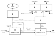
- FIG. 1 is a process flow diagram of a urea production apparatus using the urea production method of the present invention. Each process and each unit will be explained below.
- the electrolysis unit (E) shown in FIG. 1 is a unit that performs an electrolysis process to produce hydrogen and oxygen by electrolyzing water.
- the specific electrolysis conditions and the configuration of the electrolysis unit (E) in this electrolysis step known conditions and configurations related to water electrolysis technology can be adopted without restriction.
- water is supplied to the electrolysis unit (E). Hydrogen and oxygen are then produced by electrolyzing this water. At least a portion of the obtained hydrogen is supplied to an ammonia synthesis unit (N) described later and used as a raw material for synthesizing ammonia. On the other hand, at least a portion of the obtained oxygen is supplied to an oxyfuel combustion unit (O) to be described later, and used as a raw material for producing carbon dioxide.
- E electrolysis unit
- O oxyfuel combustion unit
- Electricity is required to perform the electrolysis process.
- the type of power used is not particularly limited. However, from the viewpoint of environmental protection, it is preferable to use electricity generated by renewable energy.
- Renewable energy is energy that always exists in nature, such as biomass fuel, solar power, wind power, geothermal power, and hydropower.
- generating electricity using the heat of combustion of biomass fuel is advantageous in that it is carbon neutral.
- solar power, wind power, geothermal power, or hydropower it is advantageous in that no carbon dioxide is emitted during power generation.
- biomass fuel is used as a fuel in the oxyfuel combustion unit (O) described later, power is generated using the combustion heat, and at least a part of the obtained power is used as power for the electrolysis process. It is also possible to do so.
- the air separation unit (A) shown in FIG. 1 is a unit that performs an air separation process of separating and recovering nitrogen from air. Furthermore, this air separation step may be a step of separating and recovering nitrogen from air and producing a gas containing a high concentration of oxygen.
- this air separation step may be a step of separating and recovering nitrogen from air and producing a gas containing a high concentration of oxygen.
- known conditions and configurations related to air separation technology can be adopted without restriction. Specific examples thereof include cryogenic separation method and pressure swing absorption technology (PSA).
- air is supplied to the air separation unit (A). Nitrogen is then separated and recovered from this air to produce a gas containing a high concentration of oxygen (the oxygen concentration in the gas is usually 90% to 100% by volume, hereinafter referred to as "highly concentrated oxygen"). At least a portion of the separated and recovered nitrogen is supplied to an ammonia synthesis unit (N) to be described later, and used as a raw material for synthesizing ammonia. On the other hand, at least a portion of the obtained highly concentrated oxygen is supplied to an oxyfuel combustion unit (O) described later and used as a raw material for producing carbon dioxide.
- an oxyfuel combustion unit (O) described later and used as a raw material for producing carbon dioxide.
- the high concentration oxygen produced in the air separation unit (A) is supplied to the oxyfuel combustion unit (O), but the present invention is not limited to this.
- the required amount of carbon dioxide can be sufficiently produced by supplying only the oxygen produced in the electrolysis unit (E) to the oxyfuel combustion unit (O)
- the high concentration oxygen produced in the air separation unit (A) For example, it may be collected outside the system without being supplied to the oxyfuel combustion unit (O).
- the configuration of the air separation unit (A) may be simplified by adopting a configuration in which nitrogen is separated and recovered from air but high concentration oxygen is not particularly produced.
- ammonia synthesis unit (N) The ammonia synthesis unit (N) shown in Figure 1 is an ammonia synthesis unit that synthesizes ammonia using at least part of the hydrogen produced in the electrolysis process and at least part of the nitrogen separated and recovered in the air separation process as raw materials. It is a unit that performs a process. Regarding the specific synthesis conditions and the configuration of the ammonia synthesis unit (N) in this ammonia synthesis step, known conditions and configurations related to ammonia synthesis technology can be employed without restriction. Specific examples thereof include the Haber method and other industrial ammonia synthesis methods.
- the ammonia synthesis unit (N) is supplied with hydrogen from the electrolysis unit (E) and nitrogen from the air separation unit (A). Then, ammonia is synthesized using this hydrogen and nitrogen as raw materials. At least a portion of the obtained ammonia is supplied to the urea synthesis unit (U) described later and used as a raw material for producing urea.
- the oxy-combustion unit (O) shown in FIG. 1 is a unit that performs an oxy-combustion process in which at least part of the oxygen produced in the electrolysis process is used to combust fuel to produce carbon dioxide.
- the specific combustion conditions in this oxy-combustion step and the configuration of the oxy-combustion unit (O) known conditions and configurations related to carbon dioxide production technology through combustion can be adopted without restriction.
- the embodiment shown in FIG. 1 is an embodiment in which carbon dioxide is produced by burning fuel using at least part of the oxygen produced in the electrolysis process and at least part of the highly concentrated oxygen produced in the air separation process. be.
- Such an embodiment is a particularly preferred embodiment when the amount of oxygen produced in the electrolysis process alone is insufficient, such as in the case described above using Equation 4 (when fossil fuel is used).
- the present invention is not limited to this embodiment. For example, in the case explained earlier using Equation 3 (when biomass fuel is used), if the supply of oxygen produced in the electrolysis process is sufficient, the high concentration from the air separation unit (A) There is no need to supply oxygen.
- the oxyfuel combustion unit (O) is supplied with oxygen from the electrolysis unit (E) and highly concentrated oxygen from the air separation unit (A). This oxygen and highly concentrated oxygen are then used to combust fuel and produce carbon dioxide. At least a portion of the obtained carbon dioxide is supplied to a urea synthesis unit (U) described later and used as a raw material for producing urea.
- the type of fuel used in the oxyfuel combustion process is not particularly limited. Specific examples thereof include biomass fuels such as wood pellets, organic wastes such as municipal garbage, and fossil fuels such as natural gas, oil, and coal. In particular, biomass fuel is preferable because it is carbon neutral compared to fossil fuels.
- the urea synthesis unit (U) shown in Fig. 1 is a urea synthesis unit that synthesizes urea using at least a part of carbon dioxide produced in an oxy-combustion process and at least a part of ammonia produced in an ammonia synthesis process as raw materials. It is a unit that performs a process. Regarding the specific synthesis conditions and configuration of the urea synthesis unit (U) in this urea synthesis step, known conditions and configurations related to urea synthesis technology can be employed without restriction.
- the urea synthesis unit (U) is supplied with carbon dioxide from the oxyfuel combustion unit (O) and ammonia from the ammonia synthesis unit (N). Urea is then synthesized using this carbon dioxide and ammonia as raw materials.
- the power generation unit (S) is a power generation unit that performs a power generation process of generating electricity using at least a portion of the thermal energy generated by combustion in the oxyfuel combustion process, and/or a power generation unit that performs a power generation process that uses at least a portion of the thermal energy generated by combustion in the oxyfuel combustion process, and/or a power generation unit that performs a power generation process that uses at least a portion of the thermal energy generated by combustion in the oxyfuel combustion process.
- This is a power generation unit that performs a power generation process of generating power using at least a part of the steam produced using a part of the steam.
- known conditions and configurations related to power generation technology can be adopted without restriction.
- the power generation unit (S) is a power generation unit that performs a steam turbine power generation process that generates power using steam.
- steam is supplied to the power generation unit (S) from an oxyfuel combustion unit (O) and an ammonia synthesis unit (N). This steam is then used to generate electricity through a turbine.
- the obtained electric power (P) can also be used, for example, in one or more processes selected from the group consisting of a urea synthesis process, an ammonia synthesis process, and an electrolysis process.
- An embodiment having a steam turbine power generation unit as the power generation unit (S) as shown in FIG. 1 is a preferred embodiment of the present invention.
- the steam comprises steam produced using at least a portion of the heat generated by combustion in the oxy-combustion unit (O). Since a relatively large amount of oxygen is supplied to the oxyfuel combustion unit (O) shown in FIG. 1, the amount of heat generated by combustion is also large. As a result, even if steam is supplied to the urea synthesis unit (U), the surplus steam can be used for power generation.
- the steam is not only steam produced using at least a part of the heat generated by combustion in the oxyfuel combustion unit (O), but also a reaction for ammonia synthesis in the ammonia synthesis unit (N). It also includes steam produced using at least a portion of the heat (for example, steam produced using heat exchange equipment that cools and condenses synthesized ammonia gas). Therefore, the amount of power generated will further increase.
- the present invention may include other equipment in addition to the units described above.
- other equipment include heat exchange equipment that produces steam using combustion heat, and carbon dioxide purification equipment (for example, equipment for dehydration and impurity removal).
- the present invention is not limited to the embodiment shown in FIG. 1 described above.
- a steam turbine power generation unit was used as the power generation unit (S).
- other power generation units may be added to this, or the steam turbine power generation unit may be replaced with other power generation units.
- the other power generation unit is, for example, a unit that performs a power generation process in which at least part of the thermal energy generated by combustion in the oxyfuel combustion process is directly used to generate electricity.
- Specific examples thereof include a unit that performs a gas turbine power generation process and a unit that performs a supercritical CO 2 cycle power generation process.
- Example 1 ( Figure 2)>
- E 16 t/h of hydrogen and 128 t/h of oxygen were produced from 144 t/h of water by electrolysis.
- air separation unit (A) 75 t/h of nitrogen was separated and recovered from 99 t/h of air.
- 91 t/h of ammonia was synthesized in the ammonia synthesis unit (N).
- the heat of combustion of the biomass was 2,873 kcal/kg, and the calorific value in the oxyfuel combustion unit (O) was approximately 241 MW.
- This heat was recovered to produce 264 t/h of steam.
- 139 t/h of steam was supplied to the urea synthesis unit (U) and used.
- the remaining steam was supplied to the steam turbine power generation unit (S).
- steam produced by recovering the reaction heat generated in the ammonia synthesis unit (N) was also supplied to the steam turbine power generation unit (S). Then, this steam was used to generate electricity, and 24 MW of electricity was obtained. A part of this electric power was supplied to the urea synthesis unit (U) to cover the required electric power of 7 MW.
- Example 2 ( Figure 3)>
- E 16 t/h of hydrogen and 128 t/h of oxygen were produced from 144 t/h of water by electrolysis.
- air separation unit (A) 75 t/h of nitrogen was separated and recovered from 99 t/h of air, producing 23 t/h of gas containing high concentration oxygen (oxygen concentration of approximately 98%).
- 91 t/h of ammonia was synthesized in the ammonia synthesis unit (N).
- the 104 t/h of carbon dioxide obtained as above and 80 t/h of the 91 t/h of ammonia produced in the ammonia synthesis unit (N) are supplied to the urea synthesis unit (U), producing 142 t/h of urea. did. Note that the remaining ammonia (11 t/h) was recovered outside the system.
- the heat of combustion of natural gas was 11,950 kcal/kg, and the calorific value in the oxyfuel combustion unit (O) was approximately 529 MW. This heat was recovered to produce 580 t/h of steam. Of this 580 t/h of steam, 123 t/h of steam was supplied to the urea synthesis unit (U) and used. The remaining steam was supplied to the steam turbine power generation unit (S). Furthermore, steam produced by recovering the reaction heat generated in the ammonia synthesis unit (N) was also supplied to the steam turbine power generation unit (S). The steam was then used to generate electricity, yielding 86 MW of electricity. A part of this electric power was supplied to the urea synthesis unit (U) to cover the required electric power of 6 MW.
- the heat of combustion of natural gas was 11,950 kcal/kg, and the calorific value in the oxyfuel combustion unit (O) was approximately 594 MW. This heat was recovered to produce 652 t/h of steam. Of this 652 t/h of steam, 139 t/h of steam was supplied to the urea synthesis unit (U) and used. The remaining steam was supplied to the steam turbine power generation unit (S). Furthermore, steam produced by recovering the reaction heat generated in the ammonia synthesis unit (N) was also supplied to the steam turbine power generation unit (S). The steam was then used to generate electricity, yielding 97MW of electricity. A part of this electric power was supplied to the urea synthesis unit (U) to cover the required electric power of 7 MW.
- the heat of combustion of natural gas was 11,950 kcal/kg, and the calorific value in the oxyfuel combustion unit (O) was approximately 83 MW. This heat was recovered to produce 91 t/h of steam. Of this 91 t/h of steam, 19 t/h of steam was supplied to the urea synthesis unit (U) and used. The remaining steam was supplied to the steam turbine power generation unit (S). Furthermore, steam produced by recovering the reaction heat generated in the ammonia synthesis unit (N) was also supplied to the steam turbine power generation unit (S). The steam was then used to generate electricity, yielding 14 MW of electricity. A part of this electric power was supplied to the urea synthesis unit (U) to cover the required electric power of 1 MW.
- Table 1 The results of the above Examples and Comparative Examples are summarized in Table 1. Note that the raw material consumption rate in Table 1 represents the raw material consumption amount per urea production amount (t/t-urea), but nitrogen and oxygen are calculated as the intermediate production amount per urea production amount.
- Example 1 is an example in which biomass was used as the fuel.
- all the oxygen required for the oxyfuel combustion unit (O) could be provided by the oxygen produced by the electrolysis unit (E).
- the configuration of the air separation unit (A) could be simplified, and the entire amount of produced ammonia could be used for urea synthesis, making it possible to eliminate the generation of surplus ammonia.
- steam was generated and effectively utilized using the heat generated by combustion. Therefore, Example 1 has no waste from the viewpoint of urea production and is very excellent in terms of equipment configuration and material balance.
- Example 2 is an example in which natural gas was used as the fuel.
- the amount of oxygen required for oxy-combustion is greater than when using biomass. Therefore, in this Example 2, the oxygen produced in the electrolysis unit (E) and the air separation unit (A) was supplied together to the oxyfuel combustion unit (O).
- the oxygen produced in the electrolysis unit (E) and the air separation unit (A) was supplied together to the oxyfuel combustion unit (O).
- the raw material consumption rates of nitrogen and hydrogen were 0.53 and 0.11.
- this Example 2 is superior to Comparative Example 1 in terms of material balance for urea production. Additionally, surplus ammonia can be shipped as a by-product.
- Example 3 is an example in which natural gas was used as the fuel and the amount of oxygen produced was increased in order to achieve the same urea production amount (160 t/h) as in Example 1.
- an air separation unit (A) having approximately twice the production capacity as the air separation unit (A) used in Examples 1 and 2 was used.
- the generation of excess ammonia could be reduced to zero.
- the raw material consumption rates of nitrogen and hydrogen were 0.89 and 0.10.
- the amount of steam generated and the amount of electric power obtained by the steam turbine power generation unit (S) were increased compared to Examples 1 and 2.
- Example 1 is superior in terms of reducing the capacity of the air separation unit (A).
- Comparative Example 1 is an example in which the electrolysis unit (E) was not used.
- Comparative Example 1 since oxygen only from the air separation unit (A) was used, the amount of oxygen was small and the amount of carbon dioxide obtained from the oxyfuel combustion unit (O) was small.
- the urea production amount was as low as 22 t/h, 78 t/h of surplus ammonia was generated, and the nitrogen and hydrogen raw material consumption rates were 3.41 and 0.73, the worst of the four cases.
- the material balance during the production of urea is improved, so it is very useful as an industrial urea production method and urea production apparatus.
Abstract
Disclosed is a urea production method and a urea production apparatus with which hydrogen and oxygen are generated by electrolysis of water in an electrolysis unit (E), nitrogen is separated from air and recovered in an air separation unit (A), ammonia is synthesized in an ammonia synthesis unit (N) using the hydrogen from the electrolysis unit (E) and the nitrogen from the air separation unit (A) as starting materials, carbon dioxide is generated by combusting fuel in an oxygen combustion unit (O) using at least the oxygen from the electrolysis unit (E), and urea is synthesized in a urea synthesis unit (U) using the carbon dioxide and ammonia as starting materials.
Description
本発明は尿素を製造する尿素製造方法及び尿素製造装置に関し、より詳しくは水の電気分解により生成される酸素を燃焼装置に供して、その燃焼排気ガスである二酸化炭素を原料として用いる尿素製造方法及び尿素製造装置に関する。
The present invention relates to a urea production method and a urea production apparatus for producing urea, and more specifically to a urea production method in which oxygen produced by electrolysis of water is supplied to a combustion apparatus and carbon dioxide, which is the combustion exhaust gas, is used as a raw material. and urea production equipment.
尿素プラントにおいて尿素を製造する為には、その原料としてアンモニアと二酸化炭素が必要となる。これら原料のうち、アンモニアは窒素と水素から合成できることが知られている。また二酸化炭素は、例えば燃料を燃焼させることにより得られる。
In order to produce urea in a urea plant, ammonia and carbon dioxide are required as raw materials. Among these raw materials, it is known that ammonia can be synthesized from nitrogen and hydrogen. Carbon dioxide can also be obtained, for example, by burning fuel.
特許文献1には、空気から窒素を分離回収し、この窒素を水素と反応させてアンモニア合成する方法が記載されている。また、窒素を分離した後のガス、すなわち高濃度の酸素を含むガスを使用して燃料を燃焼させて二酸化炭素を生成し、この二酸化炭素とアンモニアを原料として使用して尿素を製造する方法も記載されている。
Patent Document 1 describes a method of separating and recovering nitrogen from air and reacting this nitrogen with hydrogen to synthesize ammonia. Another method is to use gas after nitrogen has been separated, that is, gas containing high concentration of oxygen, to burn fuel to produce carbon dioxide, and to use this carbon dioxide and ammonia as raw materials to produce urea. Are listed.
しかしながら、特許文献1に記載される方法は、単にアンモニアの合成を伴う酸素燃焼システムの改善を主目的とする方法であり、尿素の製造を主目的とする方法ではない。そして、特許文献1に記載に従ってアンモニアと二酸化炭素を原料として尿素を製造する場合は、生成する二酸化炭素の量が少ないのでアンモニアの余剰量が非常に多くなる。したがって、特許文献1に記載される方法は、尿素を製造する為の物質収支が必ずしも十分でない。
However, the method described in Patent Document 1 is a method whose main purpose is simply to improve an oxyfuel combustion system that involves synthesis of ammonia, and is not a method whose main purpose is simply to produce urea. When urea is produced using ammonia and carbon dioxide as raw materials as described in Patent Document 1, the amount of carbon dioxide produced is small, so the surplus amount of ammonia becomes very large. Therefore, the method described in Patent Document 1 does not necessarily have a sufficient material balance for producing urea.
すなわち本発明の目的は、物質収支が改善された尿素製造方法及び尿素製造装置を提供することにある。
That is, an object of the present invention is to provide a urea production method and a urea production apparatus with improved material balance.
本発明者は、上記目的を達成する為に鋭意検討した結果、水の電気分解により得られる酸素を酸素燃焼工程に使用し、この工程で得た二酸化炭素を原料として尿素を製造することが非常に有効であることを見出し、本発明を完成するに至った。
As a result of intensive studies to achieve the above object, the inventor of the present invention found that it is extremely possible to use oxygen obtained by electrolysis of water in the oxy-combustion process and to produce urea using the carbon dioxide obtained in this process as a raw material. The present invention has been completed based on the discovery that the present invention is effective.
本発明は、水の電気分解により水素と酸素を生産する電気分解工程と、
空気から窒素を分離回収する空気分離工程と、
前記電気分解工程で生産した水素の少なくとも一部と、前記空気分離工程で分離回収した窒素の少なくとも一部とを原料として使用してアンモニアを合成するアンモニア合成工程と、
少なくとも、前記電気分解工程で生産した酸素の少なくとも一部を使用して、燃料を燃焼させて二酸化炭素を生産する酸素燃焼工程と、
前記酸素燃焼工程で生産した二酸化炭素の少なくとも一部と、前記アンモニア合成工程で生産したアンモニアの少なくとも一部とを原料として使用して尿素を合成する尿素合成工程とを有する尿素製造方法である。 The present invention includes an electrolysis process for producing hydrogen and oxygen by electrolysis of water;
an air separation process that separates and recovers nitrogen from air;
an ammonia synthesis step of synthesizing ammonia using as raw materials at least a portion of the hydrogen produced in the electrolysis step and at least a portion of the nitrogen separated and recovered in the air separation step;
an oxy-combustion step in which at least part of the oxygen produced in the electrolysis step is used to combust fuel to produce carbon dioxide;
The urea production method includes a urea synthesis step of synthesizing urea using at least a portion of the carbon dioxide produced in the oxy-combustion step and at least a portion of the ammonia produced in the ammonia synthesis step as raw materials.
さらに本発明は、水の電気分解により水素と酸素を生産する電気分解ユニット(E)と、
空気から窒素を分離回収する空気分離ユニット(A)と、
前記電気分解ユニット(E)で生産した水素の少なくとも一部と、前記空気分離ユニット(A)で分離回収した窒素の少なくとも一部とを原料として使用してアンモニアを合成するアンモニア合成ユニット(N)と、
少なくとも、前記電気分解ユニット(E)で生産した酸素の少なくとも一部を使用して、燃料を燃焼させて二酸化炭素を生産する酸素燃焼ユニット(O)と、
前記酸素燃焼ユニット(O)で生産した二酸化炭素の少なくとも一部と、前記アンモニア合成ユニット(N)で生産したアンモニアの少なくとも一部とを原料として使用して尿素を合成する尿素合成ユニット(U)とを有する尿素製造装置である。 Furthermore, the present invention includes an electrolysis unit (E) that produces hydrogen and oxygen by electrolysis of water;
an air separation unit (A) that separates and recovers nitrogen from air;
an ammonia synthesis unit (N) that synthesizes ammonia using as raw materials at least part of the hydrogen produced in the electrolysis unit (E) and at least part of the nitrogen separated and recovered in the air separation unit (A); and,
an oxyfuel combustion unit (O) that uses at least a portion of the oxygen produced in the electrolysis unit (E) to combust fuel and produce carbon dioxide;
A urea synthesis unit (U) that synthesizes urea using as raw materials at least part of the carbon dioxide produced in the oxyfuel combustion unit (O) and at least part of the ammonia produced in the ammonia synthesis unit (N). This is a urea production apparatus having the following.
工業的な水素の供給法としては、軽質炭化水素(軽質ナフサ、天然ガスなど)の水蒸気改質法や、石油精製における重質ナフサの接触改質法などが知られている。一方、水を電気分解することにより水素を製造する電気分解法も知られている。この電気分解法では水を原料とし、水素と酸素が生成する。そして、電気分解法で生成した酸素は、通常、大気に放散される。本発明者らは、この電気分解法により得た水素をアンモニア合成の原料として使用すると共に、通常は大気に放散されていた酸素も同時に利用することが非常に有効である点に着目した。すなわち本発明においては、水の電気分解により得た酸素を酸素燃焼工程に使用し、この工程で得た二酸化炭素を原料として尿素を製造するので、酸素燃焼工程で使用できる酸素量が格段に増加する。その結果、アンモニアの余剰量が低減し、尿素を製造する為の物質収支が改善される。
As industrial hydrogen supply methods, steam reforming of light hydrocarbons (light naphtha, natural gas, etc.) and catalytic reforming of heavy naphtha in oil refining are known. On the other hand, an electrolysis method for producing hydrogen by electrolyzing water is also known. This electrolysis method uses water as a raw material and produces hydrogen and oxygen. Oxygen produced by electrolysis is usually released into the atmosphere. The present inventors have focused on the fact that it is very effective to use hydrogen obtained by this electrolysis method as a raw material for ammonia synthesis and to simultaneously utilize oxygen, which is normally released into the atmosphere. That is, in the present invention, oxygen obtained by electrolysis of water is used in the oxy-combustion process, and urea is produced using the carbon dioxide obtained in this process as a raw material, so the amount of oxygen that can be used in the oxy-combustion process is significantly increased. do. As a result, the surplus amount of ammonia is reduced and the material balance for producing urea is improved.
また、本発明においては、酸素燃焼工程で使用できる酸素量が格段に増加するので、酸素燃焼工程で得られる熱量が増加し、生産されるスチーム量が増加し、尿素合成工程が要求するスチーム量を十分賄うことができる。さらに余剰のスチームは、例えば熱源として使用でき、あるいは発電に使用できる。
In addition, in the present invention, the amount of oxygen that can be used in the oxy-combustion process is significantly increased, so the amount of heat obtained in the oxy-combustion process increases, the amount of steam produced increases, and the amount of steam required by the urea synthesis process increases. can be fully covered. Furthermore, excess steam can be used, for example, as a heat source or for power generation.
また、通常の酸素燃焼工程において利用されている、空気分離工程により得られる酸素には、少量の窒素、アルゴンが含まれている。この少量の窒素、アルゴンを含む酸素のみを酸素燃焼工程で使用すると、酸素燃焼工程により得られる二酸化炭素の純度が下がってしまう。その結果、得られた二酸化炭素を尿素合成に使用する場合は、二酸化炭素の精製工程が必要となる場合がある。一方、本発明においては、水の電気分解により得られる酸素を酸素燃焼工程に使用し、その酸素は窒素、アルゴンをほとんど含まないので、二酸化炭素の精製工程が必要となる場合が少なくなり、工程を簡略化することもできる。
Additionally, the oxygen obtained through the air separation process, which is used in the normal oxygen combustion process, contains small amounts of nitrogen and argon. If only this small amount of oxygen containing nitrogen and argon is used in the oxy-combustion process, the purity of the carbon dioxide obtained through the oxy-combustion process will decrease. As a result, when the obtained carbon dioxide is used for urea synthesis, a carbon dioxide purification step may be necessary. On the other hand, in the present invention, oxygen obtained by electrolysis of water is used in the oxygen combustion process, and since the oxygen contains almost no nitrogen or argon, the need for a carbon dioxide purification process is reduced, and the process can also be simplified.
本発明において、アンモニアの余剰量が低減する理由を以下に説明する。
The reason why the surplus amount of ammonia is reduced in the present invention will be explained below.
まず、特許文献1に記載のような方法、すなわち酸素燃焼工程に使用する酸素は、空気分離工程によって得た酸素のみであり、本発明のような電気分解工程は行わない方法では、アンモニアの余剰量が多くなる。例えば、この方法において酸素燃焼工程にバイオマス燃料(セルロースC6H10O5で代表する)を使用した場合、その反応式は以下の式1のようになる。
First, the method described in Patent Document 1, that is, the oxygen used in the oxyfuel combustion process is only the oxygen obtained in the air separation process, and in the method of the present invention, which does not include the electrolysis process, surplus ammonia is used. The amount increases. For example, when biomass fuel (represented by cellulose C 6 H 10 O 5 ) is used in the oxyfuel combustion process in this method, the reaction formula is as shown in Formula 1 below.

式1の左辺(原料系)においては、窒素(N2)1当量を基準として各成分の比率を定めた。水素(H2)については、アンモニア合成の理論当量(H2:N2=3:1)の当量比「3」を比率として採用した。酸素(O2)については、空気分離工程において使用する空気の組成はO2=20.9%、N2=78.1%であるが、単純化のため窒素(N2)に対する酸素(O2)の比率を「1/4」と見なし、これを当量として採用した。
In the left side of Equation 1 (raw material system), the ratio of each component was determined based on 1 equivalent of nitrogen (N 2 ). Regarding hydrogen (H 2 ), an equivalent ratio of "3", which is the theoretical equivalent for ammonia synthesis (H 2 :N 2 =3:1), was adopted as the ratio. Regarding oxygen (O 2 ), the composition of the air used in the air separation process is O 2 = 20.9% and N 2 = 78.1%, but for the sake of simplicity, the ratio of oxygen (O 2 ) to nitrogen (N 2 ) is The ratio of 2 ) was regarded as "1/4", and this was adopted as the equivalent weight.
式1の右辺(生成系)に示すように、バイオマス燃料(セルロースC6H10O5)を使用した場合は、空気分離工程から窒素の1/4当量の酸素しか得られないため、酸素燃焼工程において1/4当量の二酸化炭素(CO2)しか得られない。一方、アンモニア合成工程においては2当量のアンモニア(NH3)が生成する。したがって、両者の当量比(NH3/CO2)は8である。
As shown on the right side of Equation 1 (generation system), when biomass fuel (cellulose C 6 H 10 O 5 ) is used, only 1/4 equivalent of nitrogen can be obtained from the air separation process, so oxyfuel combustion Only 1/4 equivalent of carbon dioxide (CO 2 ) is obtained in the process. On the other hand, in the ammonia synthesis step, 2 equivalents of ammonia (NH 3 ) are produced. Therefore, the equivalent ratio of both (NH 3 /CO 2 ) is 8.
以下の式2に示すように、尿素合成のアンモニアと二酸化炭素の理論当量比は2である。したがって、特許文献1に記載のような方法(NH3/CO2=8)においては二酸化炭素が不足し、消費しきれない余剰アンモニアが大量に発生してしまう。
As shown in Equation 2 below, the theoretical equivalent ratio of ammonia and carbon dioxide for urea synthesis is 2. Therefore, in the method described in Patent Document 1 (NH 3 /CO 2 =8), carbon dioxide is insufficient and a large amount of surplus ammonia that cannot be consumed is generated.

一方、本発明のように電気分解工程によって得た酸素を酸素燃焼工程に使用すれば、アンモニアの余剰量は減少する。例えば、本発明の方法において酸素燃焼工程にバイオマス燃料(セルロースC6H10O5で代表する)を使用した場合、その反応式は以下の式3のようになる。
On the other hand, if oxygen obtained through the electrolysis process is used in the oxyfuel combustion process as in the present invention, the surplus amount of ammonia will be reduced. For example, when biomass fuel (represented by cellulose C 6 H 10 O 5 ) is used in the oxyfuel combustion step in the method of the present invention, the reaction formula is as shown in Formula 3 below.

式3の左辺(原料系)においては、窒素(N2)1当量を基準として各成分の比率を定めた。水素(H2)については、アンモニア合成の理論当量(H2:N2=3:1)の当量比「3」を比率として採用した。酸素(O2)については、水(H2O)を電気分解する際の生成比率(H2:O2=2:1)を基準として、3当量の水素(H2)を得る際に生成する酸素(O2)の当量比「3/2」を比率として採用した。
In the left side of Equation 3 (raw material system), the ratio of each component was determined based on 1 equivalent of nitrogen (N 2 ). Regarding hydrogen (H 2 ), an equivalent ratio of "3", which is the theoretical equivalent for ammonia synthesis (H 2 :N 2 =3:1), was adopted as the ratio. Regarding oxygen (O 2 ), based on the production ratio (H 2 :O 2 =2:1) when water (H 2 O) is electrolyzed, it is generated when obtaining 3 equivalents of hydrogen (H 2 ). The equivalent ratio of oxygen (O 2 ) "3/2" was adopted as the ratio.
式3の右辺(生成系)に示すように、本発明においてバイオマス燃料(セルロースC6H10O5)を使用した場合は、電気分解工程から3/2当量の酸素が得られ、酸素燃焼工程において1当量の二酸化炭素(CO2)が得られ、アンモニア合成工程において2当量のアンモニア(NH3)が得られる。したがって、両者の当量比(NH3/CO2)は2である。尿素合成の理論当量は先に述べたとおり2である。したがって、この場合の本発明の方法においては二酸化炭素は不足せず、余剰アンモニアは発生しない。
As shown on the right side of Equation 3 (generation system), when biomass fuel (cellulose C 6 H 10 O 5 ) is used in the present invention, 3/2 equivalent of oxygen is obtained from the electrolysis process, and the oxyfuel combustion process 1 equivalent of carbon dioxide (CO 2 ) is obtained in the ammonia synthesis step, and 2 equivalents of ammonia (NH 3 ) are obtained in the ammonia synthesis step. Therefore, the equivalent ratio of both (NH 3 /CO 2 ) is 2. The theoretical equivalent for urea synthesis is 2 as mentioned above. Therefore, in this case, in the method of the present invention, there is no shortage of carbon dioxide and no surplus ammonia is generated.
次に、本発明の方法において酸素燃焼工程に化石燃料(メタンCH4で代表する)を使用した場合について説明する。その場合の反応式は以下の式4のようになる。
Next, a case will be described in which fossil fuel (represented by methane CH 4 ) is used in the oxyfuel combustion step in the method of the present invention. The reaction formula in that case is as shown in Formula 4 below.

式4の左辺(原料系)の窒素(N2)、水素(H2)及び酸素(O2)の各当量比は式3と同様である。
The equivalent ratios of nitrogen (N 2 ), hydrogen (H 2 ), and oxygen (O 2 ) on the left side (raw material system) of Equation 4 are the same as in Equation 3.
式4の右辺(生成系)に示すように、本発明において化石燃料(メタンCH4)を使用した場合は、電気分解工程から3/2当量の酸素が得られ、酸素燃焼工程において3/4当量の二酸化炭素(CO2)が得られ、アンモニア合成工程において2当量のアンモニア(NH3)が得られる。したがって、両者の当量比(NH3/CO2)は8/3=約2.7である。一方、尿素合成の理論当量は先に述べたとおり2である。したがって、この場合の本発明の方法においては二酸化炭素が若干不足し、余剰アンモニアが若干発生する。ただし、特許文献1に記載のような方法(NH3/CO2=8)と比較すると、余剰アンモニアの量は著しく低減できたと言うことができる。
As shown in the right side of Equation 4 (generation system), when fossil fuel (methane CH 4 ) is used in the present invention, 3/2 equivalent of oxygen is obtained from the electrolysis process, and 3/4 equivalent is obtained from the oxyfuel combustion process. Equivalents of carbon dioxide (CO 2 ) are obtained, and in the ammonia synthesis step 2 equivalents of ammonia (NH 3 ) are obtained. Therefore, the equivalent ratio of both (NH 3 /CO 2 ) is 8/3=about 2.7. On the other hand, the theoretical equivalent for urea synthesis is 2 as mentioned above. Therefore, in the method of the present invention in this case, there is a slight shortage of carbon dioxide and a slight surplus of ammonia is generated. However, when compared with the method described in Patent Document 1 (NH 3 /CO 2 =8), it can be said that the amount of surplus ammonia was significantly reduced.
図1は、本発明の尿素製造方法を用いた尿素製造装置のプロセスフロー図である。以下、各工程及び各ユニットについて説明する。
FIG. 1 is a process flow diagram of a urea production apparatus using the urea production method of the present invention. Each process and each unit will be explained below.
[電気分解ユニット(E)]
図1に示す電気分解ユニット(E)は、水の電気分解により水素と酸素を生産する電気分解工程を行うユニットである。この電気分解工程における具体的な電気分解条件や電気分解ユニット(E)の構成については、水の電気分解技術に関する公知の条件及び構成を制限なく採用できる。 [Electrolysis unit (E)]
The electrolysis unit (E) shown in FIG. 1 is a unit that performs an electrolysis process to produce hydrogen and oxygen by electrolyzing water. Regarding the specific electrolysis conditions and the configuration of the electrolysis unit (E) in this electrolysis step, known conditions and configurations related to water electrolysis technology can be adopted without restriction.
図1に示すように、電気分解ユニット(E)には水を供給する。そして、この水を電気分解することにより、水素と酸素を生産する。得られた水素の少なくとも一部は、後述するアンモニア合成ユニット(N)に供給し、アンモニアを合成する為の原料として使用する。一方、得られた酸素の少なくとも一部は、後述する酸素燃焼ユニット(O))に供給し、二酸化炭素を生産する為の原料として使用する。
As shown in Figure 1, water is supplied to the electrolysis unit (E). Hydrogen and oxygen are then produced by electrolyzing this water. At least a portion of the obtained hydrogen is supplied to an ammonia synthesis unit (N) described later and used as a raw material for synthesizing ammonia. On the other hand, at least a portion of the obtained oxygen is supplied to an oxyfuel combustion unit (O) to be described later, and used as a raw material for producing carbon dioxide.
電気分解工程を行う為には電力が必要である。使用する電力の種類は特に制限されない。ただし、再生可能エネルギーによって発電された電力を使用することが、環境保護の点から好ましい。再生可能エネルギーとは、バイオマス燃料、太陽光、風力、地熱、水力等の自然界に常に存在するエネルギーである。例えば、バイオマス燃料の燃焼熱を利用して発電する場合は、カーボン・ニュートラルである点で優れている。また、太陽光、風力、地熱又は水力により発電する場合は、発電の際に二酸化炭素を全く排出しない点で優れている。本発明においては、例えば、後述する酸素燃焼ユニット(O)において燃料としてバイオマス燃料を使用し、その燃焼熱により発電を行い、得られた電力の少なくとも一部を電気分解工程の為の電力として使用することも可能である。
Electricity is required to perform the electrolysis process. The type of power used is not particularly limited. However, from the viewpoint of environmental protection, it is preferable to use electricity generated by renewable energy. Renewable energy is energy that always exists in nature, such as biomass fuel, solar power, wind power, geothermal power, and hydropower. For example, generating electricity using the heat of combustion of biomass fuel is advantageous in that it is carbon neutral. Furthermore, when generating electricity using solar power, wind power, geothermal power, or hydropower, it is advantageous in that no carbon dioxide is emitted during power generation. In the present invention, for example, biomass fuel is used as a fuel in the oxyfuel combustion unit (O) described later, power is generated using the combustion heat, and at least a part of the obtained power is used as power for the electrolysis process. It is also possible to do so.
[空気分離ユニット(A)]
図1に示す空気分離ユニット(A)は、空気から窒素を分離回収する空気分離工程を行うユニットである。さらに、この空気分離工程は、空気から窒素を分離回収し且つ高濃度の酸素を含むガスを生産する工程であっても良い。この空気分離工程における具体的な分離条件や空気分離ユニット(A)の構成については、空気分離技術に関する公知の条件及び構成を制限なく採用できる。その具体例としては、深冷分離法、圧力スイング吸収技術(Pressure Swing Adsorption,PSA)が挙げられる。 [Air separation unit (A)]
The air separation unit (A) shown in FIG. 1 is a unit that performs an air separation process of separating and recovering nitrogen from air. Furthermore, this air separation step may be a step of separating and recovering nitrogen from air and producing a gas containing a high concentration of oxygen. Regarding the specific separation conditions in this air separation step and the configuration of the air separation unit (A), known conditions and configurations related to air separation technology can be adopted without restriction. Specific examples thereof include cryogenic separation method and pressure swing absorption technology (PSA).
図1に示すように、空気分離ユニット(A)には空気を供給する。そして、この空気から窒素を分離回収し、高濃度の酸素を含むガス(ガス中の酸素濃度は通常90体積%~100体積%、以下「高濃度酸素」と称す)を生産する。そして、分離回収した窒素の少なくとも一部は、後述するアンモニア合成ユニット(N)に供給し、アンモニアを合成する為の原料として使用する。一方、得られた高濃度酸素の少なくとも一部は、後述する酸素燃焼ユニット(O)に供給し、二酸化炭素を生産する為の原料として使用する。
As shown in Figure 1, air is supplied to the air separation unit (A). Nitrogen is then separated and recovered from this air to produce a gas containing a high concentration of oxygen (the oxygen concentration in the gas is usually 90% to 100% by volume, hereinafter referred to as "highly concentrated oxygen"). At least a portion of the separated and recovered nitrogen is supplied to an ammonia synthesis unit (N) to be described later, and used as a raw material for synthesizing ammonia. On the other hand, at least a portion of the obtained highly concentrated oxygen is supplied to an oxyfuel combustion unit (O) described later and used as a raw material for producing carbon dioxide.
なお、図1では空気分離ユニット(A)において生産した高濃度酸素を酸素燃焼ユニット(O)に供給しているが、本発明はこれに限定されない。例えば、電気分解ユニット(E)において生産した酸素だけを酸素燃焼ユニット(O)に供給することで必要量の二酸化炭素を十分生産できる場合は、空気分離ユニット(A)において生産した高濃度酸素は酸素燃焼ユニット(O)に供給せず、例えば系外に回収しても構わない。あるいは空気分離ユニット(A)の構成として、空気から窒素を分離回収するが、高濃度酸素は特に生産しない構成を採用することにより、ユニットの構成を簡略化しても良い。
Note that in FIG. 1, the high concentration oxygen produced in the air separation unit (A) is supplied to the oxyfuel combustion unit (O), but the present invention is not limited to this. For example, if the required amount of carbon dioxide can be sufficiently produced by supplying only the oxygen produced in the electrolysis unit (E) to the oxyfuel combustion unit (O), the high concentration oxygen produced in the air separation unit (A) For example, it may be collected outside the system without being supplied to the oxyfuel combustion unit (O). Alternatively, the configuration of the air separation unit (A) may be simplified by adopting a configuration in which nitrogen is separated and recovered from air but high concentration oxygen is not particularly produced.
[アンモニア合成ユニット(N)]
図1に示すアンモニア合成ユニット(N)は、電気分解工程で生産した水素の少なくとも一部と、空気分離工程で分離回収した窒素の少なくとも一部とを原料として使用してアンモニアを合成するアンモニア合成工程を行うユニットである。このアンモニア合成工程における具体的な合成条件やアンモニア合成ユニット(N)の構成については、アンモニア合成技術に関する公知の条件及び構成を制限なく採用できる。その具体例としては、ハーバー法やその他の工業用アンモニア合成法が挙げられる。 [Ammonia synthesis unit (N)]
The ammonia synthesis unit (N) shown in Figure 1 is an ammonia synthesis unit that synthesizes ammonia using at least part of the hydrogen produced in the electrolysis process and at least part of the nitrogen separated and recovered in the air separation process as raw materials. It is a unit that performs a process. Regarding the specific synthesis conditions and the configuration of the ammonia synthesis unit (N) in this ammonia synthesis step, known conditions and configurations related to ammonia synthesis technology can be employed without restriction. Specific examples thereof include the Haber method and other industrial ammonia synthesis methods.
図1に示すように、アンモニア合成ユニット(N)には、電気分解ユニット(E)から水素を供給し、空気分離ユニット(A)から窒素を供給する。そして、この水素及び窒素を原料として使用してアンモニアを合成する。得られたアンモニアの少なくとも一部は、後述する尿素合成ユニット(U)に供給し、尿素を製造する為の原料として使用する。
As shown in FIG. 1, the ammonia synthesis unit (N) is supplied with hydrogen from the electrolysis unit (E) and nitrogen from the air separation unit (A). Then, ammonia is synthesized using this hydrogen and nitrogen as raw materials. At least a portion of the obtained ammonia is supplied to the urea synthesis unit (U) described later and used as a raw material for producing urea.
[酸素燃焼ユニット(O)]
図1に示す酸素燃焼ユニット(O)は、少なくとも、電気分解工程で生産した酸素の少なくとも一部を使用して燃料を燃焼させて二酸化炭素を生産する酸素燃焼工程を行うユニットである。この酸素燃焼工程における具体的な燃焼条件や酸素燃焼ユニット(O)の構成については、燃焼による二酸化炭素生産技術に関する公知の条件及び構成を制限なく採用できる。 [Oxygen combustion unit (O)]
The oxy-combustion unit (O) shown in FIG. 1 is a unit that performs an oxy-combustion process in which at least part of the oxygen produced in the electrolysis process is used to combust fuel to produce carbon dioxide. Regarding the specific combustion conditions in this oxy-combustion step and the configuration of the oxy-combustion unit (O), known conditions and configurations related to carbon dioxide production technology through combustion can be adopted without restriction.
図1に示す態様は、電気分解工程で生産した酸素の少なくとも一部と、空気分離工程で生産した高濃度酸素の少なくとも一部とを使用して燃料を燃焼させて二酸化炭素を生産する態様である。このような態様は、例えば式4を用いて先に説明した場合(化石燃料を使用した場合)など、電気分解工程で生産した酸素の供給だけでは量が不足する場合に特に好ましい態様である。ただし、本発明はこの態様に限定されない。例えば式3を用いて先に説明した場合(バイオマス燃料を使用した場合)など、電気分解工程で生産した酸素の供給だけで十分な量を賄える場合は、空気分離ユニット(A)からの高濃度酸素は供給しなくても構わない。
The embodiment shown in FIG. 1 is an embodiment in which carbon dioxide is produced by burning fuel using at least part of the oxygen produced in the electrolysis process and at least part of the highly concentrated oxygen produced in the air separation process. be. Such an embodiment is a particularly preferred embodiment when the amount of oxygen produced in the electrolysis process alone is insufficient, such as in the case described above using Equation 4 (when fossil fuel is used). However, the present invention is not limited to this embodiment. For example, in the case explained earlier using Equation 3 (when biomass fuel is used), if the supply of oxygen produced in the electrolysis process is sufficient, the high concentration from the air separation unit (A) There is no need to supply oxygen.
図1に示すように、酸素燃焼ユニット(O)には、電気分解ユニット(E)から酸素を供給し、空気分離ユニット(A)から高濃度酸素を供給する。そして、この酸素及び高濃度酸素を使用して燃料を燃焼させて二酸化炭素を生産する。得られた二酸化炭素の少なくとも一部は、後述する尿素合成ユニット(U)に供給し、尿素を製造する為の原料として使用する。
As shown in FIG. 1, the oxyfuel combustion unit (O) is supplied with oxygen from the electrolysis unit (E) and highly concentrated oxygen from the air separation unit (A). This oxygen and highly concentrated oxygen are then used to combust fuel and produce carbon dioxide. At least a portion of the obtained carbon dioxide is supplied to a urea synthesis unit (U) described later and used as a raw material for producing urea.
酸素燃焼工程に使用する燃料の種類は特に制限されない。その具体例としては、木質ペレット等のバイオマス燃料、都市ゴミなどの有機質廃棄物、天然ガス、石油、石炭等の化石燃料が挙げられる。特にバイオマス燃料は、化石燃料と比べてカーボン・ニュートラルである点から好ましい。
The type of fuel used in the oxyfuel combustion process is not particularly limited. Specific examples thereof include biomass fuels such as wood pellets, organic wastes such as municipal garbage, and fossil fuels such as natural gas, oil, and coal. In particular, biomass fuel is preferable because it is carbon neutral compared to fossil fuels.
[尿素合成ユニット(U)]
図1に示す尿素合成ユニット(U)は、酸素燃焼工程で生産した二酸化炭素の少なくとも一部と、アンモニア合成工程で生産したアンモニアの少なくとも一部とを原料として使用して尿素を合成する尿素合成工程を行うユニットである。この尿素合成工程における具体的な合成条件や尿素合成ユニット(U)の構成については、尿素合成技術に関する公知の条件及び構成を制限なく採用できる。 [Urea synthesis unit (U)]
The urea synthesis unit (U) shown in Fig. 1 is a urea synthesis unit that synthesizes urea using at least a part of carbon dioxide produced in an oxy-combustion process and at least a part of ammonia produced in an ammonia synthesis process as raw materials. It is a unit that performs a process. Regarding the specific synthesis conditions and configuration of the urea synthesis unit (U) in this urea synthesis step, known conditions and configurations related to urea synthesis technology can be employed without restriction.
図1に示すように、尿素合成ユニット(U)には、酸素燃焼ユニット(O)から二酸化炭素を供給し、アンモニア合成ユニット(N)からアンモニアを供給する。そして、この二酸化炭素及びアンモニアを原料として使用して尿素を合成する。
As shown in FIG. 1, the urea synthesis unit (U) is supplied with carbon dioxide from the oxyfuel combustion unit (O) and ammonia from the ammonia synthesis unit (N). Urea is then synthesized using this carbon dioxide and ammonia as raw materials.
[発電ユニット(S)]
発電ユニット(S)は、酸素燃焼工程における燃焼により生じた熱エネルギーの少なくとも一部を使用して発電する発電工程を行う発電ユニット、及び/又は、酸素燃焼工程における燃焼により生じた熱エネルギーの少なくとも一部を使用して生産されたスチームの少なくとも一部を使用して発電する発電工程を行う発電ユニットである。この発電工程における具体的な発電条件や発電ユニット(S)の構成については、発電技術に関する公知の条件及び構成を制限なく採用できる。 [Generation unit (S)]
The power generation unit (S) is a power generation unit that performs a power generation process of generating electricity using at least a portion of the thermal energy generated by combustion in the oxyfuel combustion process, and/or a power generation unit that performs a power generation process that uses at least a portion of the thermal energy generated by combustion in the oxyfuel combustion process, and/or a power generation unit that performs a power generation process that uses at least a portion of the thermal energy generated by combustion in the oxyfuel combustion process. This is a power generation unit that performs a power generation process of generating power using at least a part of the steam produced using a part of the steam. Regarding the specific power generation conditions and configuration of the power generation unit (S) in this power generation process, known conditions and configurations related to power generation technology can be adopted without restriction.
図1に示す態様において、発電ユニット(S)は、スチームにより発電するスチームタービン発電工程を行う発電ユニットである。図1に示すように、発電ユニット(S)には、酸素燃焼ユニット(O)及びアンモニア合成ユニット(N)からスチームを供給する。そして、このスチームを使用してタービン発電を行う。得られた電力(P)は、例えば、尿素合成工程、アンモニア合成工程及び電気分解工程からなる群より選ばれた一つ以上の工程において使用する事も出来る。
In the embodiment shown in FIG. 1, the power generation unit (S) is a power generation unit that performs a steam turbine power generation process that generates power using steam. As shown in FIG. 1, steam is supplied to the power generation unit (S) from an oxyfuel combustion unit (O) and an ammonia synthesis unit (N). This steam is then used to generate electricity through a turbine. The obtained electric power (P) can also be used, for example, in one or more processes selected from the group consisting of a urea synthesis process, an ammonia synthesis process, and an electrolysis process.
図1に示すような、発電ユニット(S)としてスチームタービン発電ユニットを有する態様は、本発明において好ましい態様である。この態様においては、スチームが、酸素燃焼ユニット(O)における燃焼により生じる熱の少なくとも一部を使用して生産したスチームを含んでいる。図1に示す酸素燃焼ユニット(O)には比較的大量の酸素が供給されるので、燃焼により生じる熱量も多い。その結果、たとえ尿素合成ユニット(U)にスチームを供給しても、その余剰のスチームを発電に使用できる。
An embodiment having a steam turbine power generation unit as the power generation unit (S) as shown in FIG. 1 is a preferred embodiment of the present invention. In this embodiment, the steam comprises steam produced using at least a portion of the heat generated by combustion in the oxy-combustion unit (O). Since a relatively large amount of oxygen is supplied to the oxyfuel combustion unit (O) shown in FIG. 1, the amount of heat generated by combustion is also large. As a result, even if steam is supplied to the urea synthesis unit (U), the surplus steam can be used for power generation.
また、図1に示す態様においては、スチームが、酸素燃焼ユニット(O)における燃焼により生じる熱の少なくとも一部を使用して生産したスチームだけでなく、アンモニア合成ユニット(N)におけるアンモニア合成の反応熱の少なくとも一部を使用して生産したスチーム(例えば、合成したアンモニアガスを冷却凝縮させる熱交換設備を使用して生産したスチーム)も含んでいる。したがって、その発電量はさらに増加する。
In addition, in the embodiment shown in FIG. 1, the steam is not only steam produced using at least a part of the heat generated by combustion in the oxyfuel combustion unit (O), but also a reaction for ammonia synthesis in the ammonia synthesis unit (N). It also includes steam produced using at least a portion of the heat (for example, steam produced using heat exchange equipment that cools and condenses synthesized ammonia gas). Therefore, the amount of power generated will further increase.
本発明においては、以上説明した各ユニットに加えて他の設備を有していても良い。他の設備としては、例えば、燃焼熱でスチームを生産する熱交換設備、二酸化炭素の精製設備(例えば脱水や不純物除去などの為の設備)が挙げられる。
The present invention may include other equipment in addition to the units described above. Examples of other equipment include heat exchange equipment that produces steam using combustion heat, and carbon dioxide purification equipment (for example, equipment for dehydration and impurity removal).
本発明は、以上説明した図1に示す態様に限定されない。例えば、図1に示す態様においては、発電ユニット(S)としてスチームタービン発電ユニットを使用した。しかし、その他の発電ユニットをこれに追加しても構わないし、スチームタービン発電ユニットをその他の発電ユニットに置き換えても構わない。その他の発電ユニットは、例えば、酸素燃焼工程における燃焼により生じた熱エネルギーの少なくとも一部を直接使用して発電する発電工程を行うユニットである。その具体例としては、ガスタービン発電工程を行うユニット、超臨界CO2サイクル発電工程を行うユニットが挙げられる。
The present invention is not limited to the embodiment shown in FIG. 1 described above. For example, in the embodiment shown in FIG. 1, a steam turbine power generation unit was used as the power generation unit (S). However, other power generation units may be added to this, or the steam turbine power generation unit may be replaced with other power generation units. The other power generation unit is, for example, a unit that performs a power generation process in which at least part of the thermal energy generated by combustion in the oxyfuel combustion process is directly used to generate electricity. Specific examples thereof include a unit that performs a gas turbine power generation process and a unit that performs a supercritical CO 2 cycle power generation process.
以下、本発明を実施例によって更に具体的に説明する。ただし本発明は実施例により制限されるものではない。
Hereinafter, the present invention will be explained in more detail with reference to Examples. However, the present invention is not limited to the examples.
<実施例1(図2)>
電気分解ユニット(E)において、電気分解により水144t/hから水素16t/h及び酸素128t/hを生産した。また、空気分離ユニット(A)において、空気99t/hから窒素75t/hを分離回収した。そして、この水素16t/h及び窒素75t/hを原料として使用して、アンモニア合成ユニット(N)においてアンモニア91t/hを合成した。 <Example 1 (Figure 2)>
In the electrolysis unit (E), 16 t/h of hydrogen and 128 t/h of oxygen were produced from 144 t/h of water by electrolysis. Further, in the air separation unit (A), 75 t/h of nitrogen was separated and recovered from 99 t/h of air. Using 16 t/h of hydrogen and 75 t/h of nitrogen as raw materials, 91 t/h of ammonia was synthesized in the ammonia synthesis unit (N).
電気分解ユニット(E)において生産した酸素128t/hのうちの86t/hの酸素と、燃料としてのバイオマス72t/hとを酸素燃焼ユニット(O)に供給し、バイオマス(木質ペレット)を燃焼させた。そして、発生した燃焼ガスに対して冷却及び必要に応じて洗浄などの処理を行い、二酸化炭素118t/hを得た。なお、残りの酸素42t/hは系外へ回収した。
Out of the 128 t/h of oxygen produced in the electrolysis unit (E), 86 t/h of oxygen and 72 t/h of biomass as fuel are supplied to the oxyfuel combustion unit (O) to burn the biomass (wood pellets). Ta. Then, the generated combustion gas was cooled and, if necessary, washed, etc., to obtain 118 t/h of carbon dioxide. Note that the remaining oxygen (42 t/h) was recovered outside the system.
以上のようにして得た二酸化炭素118t/hと、アンモニア合成ユニット(N)において生産したアンモニア91t/hとを尿素合成ユニット(U)に供給し、尿素161t/hを生産した。
118 t/h of carbon dioxide obtained as above and 91 t/h of ammonia produced in the ammonia synthesis unit (N) were supplied to the urea synthesis unit (U) to produce 161 t/h of urea.
バイオマスの燃焼熱は2,873kcal/kgであり、酸素燃焼ユニット(O)における発熱量は約241MWであった。この熱を回収してスチーム264t/hを生産した。このスチーム264t/hのうち、139t/hのスチームを尿素合成ユニット(U)に供給して使用した。残りのスチームはスチームタービン発電ユニット(S)に供給した。さらに、アンモニア合成ユニット(N)において生じた反応熱を回収して生産したスチームも、スチームタービン発電ユニット(S)に供給した。そして、これらのスチームを使用して発電を行い、24MWの電力を得た。この電力の一部は尿素合成ユニット(U)に供給して、必要となる電力7MWを賄った。
The heat of combustion of the biomass was 2,873 kcal/kg, and the calorific value in the oxyfuel combustion unit (O) was approximately 241 MW. This heat was recovered to produce 264 t/h of steam. Of this 264 t/h of steam, 139 t/h of steam was supplied to the urea synthesis unit (U) and used. The remaining steam was supplied to the steam turbine power generation unit (S). Furthermore, steam produced by recovering the reaction heat generated in the ammonia synthesis unit (N) was also supplied to the steam turbine power generation unit (S). Then, this steam was used to generate electricity, and 24 MW of electricity was obtained. A part of this electric power was supplied to the urea synthesis unit (U) to cover the required electric power of 7 MW.
<実施例2(図3)>
電気分解ユニット(E)において、電気分解により水144t/hから水素16t/h及び酸素128t/hを生産した。また、空気分離ユニット(A)において、空気99t/hから窒素75t/hを分離回収し、高濃度の酸素を含むガス23t/h(酸素濃度約98%)を生産した。そして、この水素16t/h及び窒素75t/hを原料として使用して、アンモニア合成ユニット(N)においてアンモニア91t/hを合成した。 <Example 2 (Figure 3)>
In the electrolysis unit (E), 16 t/h of hydrogen and 128 t/h of oxygen were produced from 144 t/h of water by electrolysis. In addition, in the air separation unit (A), 75 t/h of nitrogen was separated and recovered from 99 t/h of air, producing 23 t/h of gas containing high concentration oxygen (oxygen concentration of approximately 98%). Using 16 t/h of hydrogen and 75 t/h of nitrogen as raw materials, 91 t/h of ammonia was synthesized in the ammonia synthesis unit (N).
電気分解ユニット(E)において生産した酸素128t/h及び空気分離ユニット(A)において生産した高濃度の酸素を含むガス23t/h(合計151t/h)と、燃料としての天然ガス38t/hとを酸素燃焼ユニット(O)に供給し、天然ガスを燃焼させた。発生した燃焼ガスに対して冷却及び必要に応じて洗浄などの処理を行い、二酸化炭素104t/hを得た。
128 t/h of oxygen produced in the electrolysis unit (E), 23 t/h of gas containing high concentration oxygen produced in the air separation unit (A) (total 151 t/h), and 38 t/h of natural gas as fuel. was supplied to the oxyfuel combustion unit (O) to combust the natural gas. The generated combustion gas was cooled and, if necessary, washed, etc., to obtain 104 t/h of carbon dioxide.
以上のようにして得た二酸化炭素104t/hと、アンモニア合成ユニット(N)において生産したアンモニア91t/hのうち80t/hとを尿素合成ユニット(U)に供給し、尿素142t/hを生産した。なお、残りのアンモニア11t/hは系外へ回収した。
The 104 t/h of carbon dioxide obtained as above and 80 t/h of the 91 t/h of ammonia produced in the ammonia synthesis unit (N) are supplied to the urea synthesis unit (U), producing 142 t/h of urea. did. Note that the remaining ammonia (11 t/h) was recovered outside the system.
天然ガスの燃焼熱は11,950kcal/kgであり、酸素燃焼ユニット(O)における発熱量は約529MWであった。この熱を回収してスチーム580t/hを生産した。このスチーム580t/hのうち、123t/hのスチームを尿素合成ユニット(U)に供給して使用した。残りのスチームはスチームタービン発電ユニット(S)に供給した。さらに、アンモニア合成ユニット(N)において生じた反応熱を回収して生産したスチームも、スチームタービン発電ユニット(S)に供給した。そして、これらのスチームを使用して発電を行い、86MWの電力を得た。この電力の一部は尿素合成ユニット(U)に供給して、必要となる電力6MWを賄った。
The heat of combustion of natural gas was 11,950 kcal/kg, and the calorific value in the oxyfuel combustion unit (O) was approximately 529 MW. This heat was recovered to produce 580 t/h of steam. Of this 580 t/h of steam, 123 t/h of steam was supplied to the urea synthesis unit (U) and used. The remaining steam was supplied to the steam turbine power generation unit (S). Furthermore, steam produced by recovering the reaction heat generated in the ammonia synthesis unit (N) was also supplied to the steam turbine power generation unit (S). The steam was then used to generate electricity, yielding 86 MW of electricity. A part of this electric power was supplied to the urea synthesis unit (U) to cover the required electric power of 6 MW.
<実施例3(図4)>
電気分解ユニット(E)において、電気分解により水144t/hから水素16t/h及び酸素128t/hを生産した。また、空気分離ユニット(A)において、空気190t/hから窒素143t/hを分離回収し、高濃度の酸素を含むガス45t/h(酸素濃度約98%)を生産した。そして、この水素16t/hと、窒素143t/hのうち75t/hとを原料として使用して、アンモニア合成ユニット(N)においてアンモニア91t/hを合成した。なお、残りの窒素68t/hは系外へ回収した。 <Example 3 (Figure 4)>
In the electrolysis unit (E), 16 t/h of hydrogen and 128 t/h of oxygen were produced from 144 t/h of water by electrolysis. In addition, in the air separation unit (A), 143 t/h of nitrogen was separated and recovered from 190 t/h of air, producing 45 t/h of gas containing high concentration oxygen (oxygen concentration approximately 98%). Using 16 t/h of this hydrogen and 75 t/h of the 143 t/h of nitrogen as raw materials, 91 t/h of ammonia was synthesized in the ammonia synthesis unit (N). The remaining nitrogen, 68 t/h, was recovered to the outside of the system.
電気分解ユニット(E)において生産した酸素128t/h及び空気分離ユニット(A)において生産した高濃度の酸素を含むガス45t/h(合計173t/h)と、燃料としての天然ガス43t/hとを酸素燃焼ユニット(O)に供給し、天然ガスを燃焼させた。発生した燃焼ガスに対して冷却及び必要に応じて洗浄などの処理を行い、二酸化炭素118t/hを得た。
128 t/h of oxygen produced in the electrolysis unit (E), 45 t/h of gas containing high concentration oxygen produced in the air separation unit (A) (total 173 t/h), and 43 t/h of natural gas as fuel. was supplied to the oxyfuel combustion unit (O) to combust the natural gas. The generated combustion gas was cooled and, if necessary, washed, etc., to obtain 118 t/h of carbon dioxide.
以上のようにして得た二酸化炭素118t/hと、アンモニア合成ユニット(N)において生産したアンモニア91t/hとを尿素合成ユニット(U)に供給し、尿素161t/hを生産した。
118 t/h of carbon dioxide obtained as above and 91 t/h of ammonia produced in the ammonia synthesis unit (N) were supplied to the urea synthesis unit (U) to produce 161 t/h of urea.
天然ガスの燃焼熱は11,950kcal/kgであり、酸素燃焼ユニット(O)における発熱量は約594MWであった。この熱を回収してスチーム652t/hを生産した。このスチーム652t/hのうち、139t/hのスチームを尿素合成ユニット(U)に供給して使用した。残りのスチームはスチームタービン発電ユニット(S)に供給した。さらに、アンモニア合成ユニット(N)において生じた反応熱を回収して生産したスチームも、スチームタービン発電ユニット(S)に供給した。そして、これらのスチームを使用して発電を行い、97MWの電力を得た。この電力の一部は尿素合成ユニット(U)に供給して、必要となる電力7MWを賄った。
The heat of combustion of natural gas was 11,950 kcal/kg, and the calorific value in the oxyfuel combustion unit (O) was approximately 594 MW. This heat was recovered to produce 652 t/h of steam. Of this 652 t/h of steam, 139 t/h of steam was supplied to the urea synthesis unit (U) and used. The remaining steam was supplied to the steam turbine power generation unit (S). Furthermore, steam produced by recovering the reaction heat generated in the ammonia synthesis unit (N) was also supplied to the steam turbine power generation unit (S). The steam was then used to generate electricity, yielding 97MW of electricity. A part of this electric power was supplied to the urea synthesis unit (U) to cover the required electric power of 7 MW.
<比較例1(図5)>
空気分離ユニット(A)において、空気99t/hから窒素75t/hを分離回収し、高濃度の酸素を含むガス23t/h(酸素濃度約98%)を生産した。そして、別途用意した水素16t/hと、空気分離ユニット(A)において回収した窒素75t/hとを原料として使用して、アンモニア合成ユニット(N)においてアンモニア91t/hを合成した。 <Comparative example 1 (Figure 5)>
In the air separation unit (A), 75 t/h of nitrogen was separated and recovered from 99 t/h of air, producing 23 t/h of gas containing high concentration oxygen (oxygen concentration of approximately 98%). Then, 91 t/h of ammonia was synthesized in the ammonia synthesis unit (N) using 16 t/h of separately prepared hydrogen and 75 t/h of nitrogen recovered in the air separation unit (A) as raw materials.
空気分離ユニット(A)において生産した高濃度の酸素を含むガス23t/hと、燃料としての天然ガス6t/hとを酸素燃焼ユニット(O)に供給し、天然ガスを燃焼させた。発生した燃焼ガスに対して冷却及び洗浄などの処理を行い、二酸化炭素16t/hを得た。
23 t/h of gas containing highly concentrated oxygen produced in the air separation unit (A) and 6 t/h of natural gas as fuel were supplied to the oxyfuel combustion unit (O), and the natural gas was combusted. The generated combustion gas was subjected to treatments such as cooling and cleaning, and 16 t/h of carbon dioxide was obtained.
以上のようにして得た二酸化炭素16t/hと、アンモニア合成ユニット(N)において生産したアンモニア91t/hのうち12t/hとを尿素合成ユニット(U)に供給し、尿素22t/hを生産した。なお、残りのアンモニア79t/hは系外へ回収した。
The 16 t/h of carbon dioxide obtained as above and 12 t/h of the 91 t/h of ammonia produced in the ammonia synthesis unit (N) are supplied to the urea synthesis unit (U), producing 22 t/h of urea. did. Note that the remaining ammonia 79 t/h was recovered outside the system.
天然ガスの燃焼熱は11,950kcal/kgであり、酸素燃焼ユニット(O)における発熱量は約83MWであった。この熱を回収してスチーム91t/hを生産した。このスチーム91t/hのうち、19t/hのスチームを尿素合成ユニット(U)に供給して使用した。残りのスチームはスチームタービン発電ユニット(S)に供給した。さらに、アンモニア合成ユニット(N)において生じた反応熱を回収して生産したスチームも、スチームタービン発電ユニット(S)に供給した。そして、これらのスチームを使用して発電を行い、14MWの電力を得た。この電力の一部は尿素合成ユニット(U)に供給して、必要となる電力1MWを賄った。
The heat of combustion of natural gas was 11,950 kcal/kg, and the calorific value in the oxyfuel combustion unit (O) was approximately 83 MW. This heat was recovered to produce 91 t/h of steam. Of this 91 t/h of steam, 19 t/h of steam was supplied to the urea synthesis unit (U) and used. The remaining steam was supplied to the steam turbine power generation unit (S). Furthermore, steam produced by recovering the reaction heat generated in the ammonia synthesis unit (N) was also supplied to the steam turbine power generation unit (S). The steam was then used to generate electricity, yielding 14 MW of electricity. A part of this electric power was supplied to the urea synthesis unit (U) to cover the required electric power of 1 MW.
以上の実施例及び比較例の結果をまとめて表1に記載する。なお、表1中の原料原単位は尿素生産量当たりの原料消費量(t/t-urea)を表しているが、窒素および酸素については尿素生産量当たりの中間製造量として計算している。
The results of the above Examples and Comparative Examples are summarized in Table 1. Note that the raw material consumption rate in Table 1 represents the raw material consumption amount per urea production amount (t/t-urea), but nitrogen and oxygen are calculated as the intermediate production amount per urea production amount.

表1に示すように、実施例1~3においては電気分解工程(及びスチームタービン発電工程)を実施したので、物質収支に関して優れた結果が得られた。一方、比較例1においては電気分解工程を実施しなかったので、実施例1~3よりも物質収支が劣っていた。具体的には以下のとおりである。
As shown in Table 1, in Examples 1 to 3, the electrolysis process (and steam turbine power generation process) was carried out, so excellent results were obtained in terms of material balance. On the other hand, in Comparative Example 1, the electrolysis step was not performed, so the material balance was inferior to Examples 1 to 3. Specifically, the details are as follows.
実施例1は、燃料としてバイオマスを使用した例である。この実施例1においては、酸素燃焼ユニット(O)に必要な酸素を、電気分解ユニット(E)で生産された酸素により全て賄うことができた。その結果、空気分離ユニット(A)の構成を簡略化することができ、しかも生産されたアンモニア全量を尿素合成に使用でき、余剰アンモニアの発生をゼロにできた。その結果、窒素および水素の原料原単位が四例中で最小値となる0.47及び0.10を達成できた。また、燃焼等により発生する熱を用いてスチームを生成して有効利用した。したがって実施例1は、尿素製造の観点から無駄が無く、設備構成、物質収支の点で非常に優れている。
Example 1 is an example in which biomass was used as the fuel. In this Example 1, all the oxygen required for the oxyfuel combustion unit (O) could be provided by the oxygen produced by the electrolysis unit (E). As a result, the configuration of the air separation unit (A) could be simplified, and the entire amount of produced ammonia could be used for urea synthesis, making it possible to eliminate the generation of surplus ammonia. As a result, we were able to achieve nitrogen and hydrogen raw material consumption rates of 0.47 and 0.10, which were the lowest values among the four examples. In addition, steam was generated and effectively utilized using the heat generated by combustion. Therefore, Example 1 has no waste from the viewpoint of urea production and is very excellent in terms of equipment configuration and material balance.
実施例2は、燃料として天然ガスを使用した例である。燃料として天然ガスを使用する場合は、バイオマスを使用する場合よりも酸素燃焼に必要な酸素量が多い。したがって、この実施例2においては、電気分解ユニット(E)及び空気分離ユニット(A)で生産される酸素を併せて酸素燃焼ユニット(O)に供給した。しかし、それでも酸素が不足、すなわち生成する二酸化炭素が不足となり、尿素製品は実施例1と比べて減り(実施例2の尿素製造量=142t/h、実施例1の尿素製造量=160t/h)、余剰アンモニアが11t/h生じた。その結果、窒素及び水素の原料原単位が0.53及び0.11となった。ただし、この実施例2は、比較例1よりも尿素製造の物質収支の点で優れている。また、余剰アンモニアは副生製品として出荷できる。
Example 2 is an example in which natural gas was used as the fuel. When using natural gas as a fuel, the amount of oxygen required for oxy-combustion is greater than when using biomass. Therefore, in this Example 2, the oxygen produced in the electrolysis unit (E) and the air separation unit (A) was supplied together to the oxyfuel combustion unit (O). However, there is still a shortage of oxygen, that is, a shortage of carbon dioxide to be produced, and the amount of urea produced decreases compared to Example 1 (urea production amount in Example 2 = 142 t/h, urea production amount in Example 1 = 160 t/h). ), surplus ammonia was generated at 11 t/h. As a result, the raw material consumption rates of nitrogen and hydrogen were 0.53 and 0.11. However, this Example 2 is superior to Comparative Example 1 in terms of material balance for urea production. Additionally, surplus ammonia can be shipped as a by-product.
実施例3は、燃料として天然ガスを使用し、かつ実施例1と同等の尿素製造量(160t/h)を達成する為に酸素の生成量を多くした例である。具体的には、この実施例3においては、実施例1及び2で使用した空気分離ユニット(A)よりも約二倍の生産能力を有する空気分離ユニット(A)を使用した。その結果、実施例1と同様に余剰アンモニアの発生をゼロにできた。その結果、窒素及び水素の原料原単位が0.89及び0.10となった。また、実施例1及び2よりもスチーム発生量やスチームタービン発電ユニット(S)で得られる電力量が増した。ただし、空気分離ユニット(A)の容量の低減化の点では実施例1の方が優れている。
Example 3 is an example in which natural gas was used as the fuel and the amount of oxygen produced was increased in order to achieve the same urea production amount (160 t/h) as in Example 1. Specifically, in this Example 3, an air separation unit (A) having approximately twice the production capacity as the air separation unit (A) used in Examples 1 and 2 was used. As a result, as in Example 1, the generation of excess ammonia could be reduced to zero. As a result, the raw material consumption rates of nitrogen and hydrogen were 0.89 and 0.10. Moreover, the amount of steam generated and the amount of electric power obtained by the steam turbine power generation unit (S) were increased compared to Examples 1 and 2. However, Example 1 is superior in terms of reducing the capacity of the air separation unit (A).
比較例1は、電気分解ユニット(E)を使用しなかった例である。この比較例1においては、空気分離ユニット(A)のみからの酸素を使用したので、その酸素量は少なく、酸素燃焼ユニット(O)から得られる二酸化炭素が少なかった。その結果、尿素生産量は22t/hと少なく、78t/hの余剰アンモニアが発生してしまい、窒素及び水素の原料原単位は四例中で最も悪い3.41および0.73となった。
Comparative Example 1 is an example in which the electrolysis unit (E) was not used. In Comparative Example 1, since oxygen only from the air separation unit (A) was used, the amount of oxygen was small and the amount of carbon dioxide obtained from the oxyfuel combustion unit (O) was small. As a result, the urea production amount was as low as 22 t/h, 78 t/h of surplus ammonia was generated, and the nitrogen and hydrogen raw material consumption rates were 3.41 and 0.73, the worst of the four cases.
本発明によれば、尿素を製造する際の物質収支が改善されるので、工業的な尿素製造方法及び尿素製造装置として非常に有用である。
According to the present invention, the material balance during the production of urea is improved, so it is very useful as an industrial urea production method and urea production apparatus.
P 電力
S 発電ユニット
O 酸素燃焼ユニット
E 電気分解ユニット
A 空気分離ユニット
N アンモニア合成ユニット
U 尿素合成ユニット
P Electric power S Power generation unit O Oxygen combustion unit E Electrolysis unit A Air separation unit N Ammonia synthesis unit U Urea synthesis unit
S 発電ユニット
O 酸素燃焼ユニット
E 電気分解ユニット
A 空気分離ユニット
N アンモニア合成ユニット
U 尿素合成ユニット
P Electric power S Power generation unit O Oxygen combustion unit E Electrolysis unit A Air separation unit N Ammonia synthesis unit U Urea synthesis unit
Claims (10)
- 水の電気分解により水素と酸素を生産する電気分解工程と、
空気から窒素を分離回収する空気分離工程と、
前記電気分解工程で生産した水素の少なくとも一部と、前記空気分離工程で分離回収した窒素の少なくとも一部とを原料として使用してアンモニアを合成するアンモニア合成工程と、
少なくとも、前記電気分解工程で生産した酸素の少なくとも一部を使用して、燃料を燃焼させて二酸化炭素を生産する酸素燃焼工程と、
前記酸素燃焼工程で生産した二酸化炭素の少なくとも一部と、前記アンモニア合成工程で生産したアンモニアの少なくとも一部とを原料として使用して尿素を合成する尿素合成工程とを有する尿素製造方法。 an electrolysis process that produces hydrogen and oxygen through electrolysis of water;
an air separation process that separates and recovers nitrogen from air;
an ammonia synthesis step of synthesizing ammonia using as raw materials at least a portion of the hydrogen produced in the electrolysis step and at least a portion of the nitrogen separated and recovered in the air separation step;
an oxy-combustion step in which at least part of the oxygen produced in the electrolysis step is used to combust fuel to produce carbon dioxide;
A urea production method comprising a urea synthesis step of synthesizing urea using as raw materials at least a portion of carbon dioxide produced in the oxy-combustion step and at least a portion of ammonia produced in the ammonia synthesis step. - 空気分離工程が、空気から窒素を分離回収し且つ高濃度の酸素を含むガスを生産する工程であり、
酸素燃焼工程において、電気分解工程で生産した酸素の少なくとも一部と、空気分離工程で生産した高濃度の酸素を含むガスの少なくとも一部とを使用して、燃料を燃焼させて二酸化炭素を生産する請求項1に記載の尿素製造方法。 The air separation process is a process of separating and recovering nitrogen from air and producing a gas containing high concentration of oxygen,
In the oxy-combustion process, fuel is combusted to produce carbon dioxide using at least part of the oxygen produced in the electrolysis process and at least part of the gas containing high concentration of oxygen produced in the air separation process. The method for producing urea according to claim 1. - 発電工程を有し、該発電工程が、酸素燃焼工程における燃焼により生じた熱エネルギーの少なくとも一部を使用して発電する発電工程、及び/又は、酸素燃焼工程における燃焼により生じた熱エネルギーの少なくとも一部を使用して生産されたスチームの少なくとも一部を使用して発電する発電工程である請求項1に記載の尿素製造方法。 a power generation step, the power generation step uses at least a portion of the thermal energy generated by combustion in the oxy-fuel combustion step, and/or a power generation step in which the power generation step generates electricity using at least a portion of the thermal energy generated by combustion in the oxy-fuel combustion step; The method for producing urea according to claim 1, which is a power generation step in which at least a portion of the steam produced using a portion of the steam is used to generate electricity.
- 発電工程において得た電力の少なくとも一部を、尿素合成工程、アンモニア合成工程及び電気分解工程からなる群より選ばれた一つ以上の工程において使用する請求項3に記載の尿素製造方法。 The method for producing urea according to claim 3, wherein at least a part of the electric power obtained in the power generation step is used in one or more steps selected from the group consisting of a urea synthesis step, an ammonia synthesis step, and an electrolysis step.
- 発電工程が、酸素燃焼工程における燃焼により生じた熱エネルギーの少なくとも一部を使用して生産されたスチーム、及び、アンモニア合成工程におけるアンモニア合成の反応熱の少なくとも一部を使用して生産されたスチームを使用して発電する発電工程である請求項3に記載の尿素製造方法。 Steam produced in the power generation process using at least part of the thermal energy generated by combustion in the oxy-combustion process, and steam produced using at least part of the reaction heat of ammonia synthesis in the ammonia synthesis process. The method for producing urea according to claim 3, which is a power generation step in which power is generated using.
- 水の電気分解により水素と酸素を生産する電気分解ユニット(E)と、
空気から窒素を分離回収する空気分離ユニット(A)と、
前記電気分解ユニット(E)で生産した水素の少なくとも一部と、前記空気分離ユニット(A)で分離回収した窒素の少なくとも一部とを原料として使用してアンモニアを合成するアンモニア合成ユニット(N)と、
少なくとも、前記電気分解ユニット(E)で生産した酸素の少なくとも一部を使用して、燃料を燃焼させて二酸化炭素を生産する酸素燃焼ユニット(O)と、
前記酸素燃焼ユニット(O)で生産した二酸化炭素の少なくとも一部と、前記アンモニア合成ユニット(N)で生産したアンモニアの少なくとも一部とを原料として使用して尿素を合成する尿素合成ユニット(U)とを有する尿素製造装置。 an electrolysis unit (E) that produces hydrogen and oxygen by electrolysis of water;
an air separation unit (A) that separates and recovers nitrogen from air;
an ammonia synthesis unit (N) that synthesizes ammonia using as raw materials at least part of the hydrogen produced in the electrolysis unit (E) and at least part of the nitrogen separated and recovered in the air separation unit (A); and,
an oxyfuel combustion unit (O) that uses at least a portion of the oxygen produced in the electrolysis unit (E) to combust fuel and produce carbon dioxide;
A urea synthesis unit (U) that synthesizes urea using as raw materials at least part of the carbon dioxide produced in the oxyfuel combustion unit (O) and at least part of the ammonia produced in the ammonia synthesis unit (N). A urea production device comprising: - 空気分離ユニット(A)が、空気から窒素を分離回収し且つ高濃度の酸素を含むガスを生産するユニットであり、
酸素燃焼ユニット(O)において、電気分解工程で生産した酸素の少なくとも一部と、空気分離工程で生産した高濃度の酸素を含むガスの少なくとも一部とを使用して、燃料を燃焼させて二酸化炭素を生産する請求項6に記載の尿素製造装置。 The air separation unit (A) is a unit that separates and recovers nitrogen from air and produces gas containing high concentration oxygen,
In the oxy-combustion unit (O), the fuel is combusted to produce carbon dioxide using at least part of the oxygen produced in the electrolysis process and at least part of the gas containing high concentration of oxygen produced in the air separation process. The urea production apparatus according to claim 6, which produces carbon. - 発電ユニット(S)を有し、該発電ユニット(S)が、酸素燃焼ユニット(O)における燃焼により生じた熱エネルギーの少なくとも一部を使用して発電する発電ユニット、及び/又は、酸素燃焼ユニット(O)における燃焼により生じた熱エネルギーの少なくとも一部を使用して生産されたスチームの少なくとも一部を使用して発電する発電ユニットである請求項6に記載の尿素製造装置。 A power generation unit having a power generation unit (S), the power generation unit (S) generating electricity using at least part of the thermal energy generated by combustion in the oxyfuel combustion unit (O), and/or an oxyfuel combustion unit The urea production apparatus according to claim 6, which is a power generation unit that generates electricity using at least a portion of steam produced using at least a portion of thermal energy generated by combustion in (O).
- 発電ユニット(S)において得た電力の少なくとも一部を、尿素合成ユニット(U)、アンモニア合成ユニット(N)及び電気分解ユニット(E)からなる群より選ばれた一つ以上のユニットにおいて使用する請求項8に記載の尿素製造装置。 At least a part of the electric power obtained in the power generation unit (S) is used in one or more units selected from the group consisting of a urea synthesis unit (U), an ammonia synthesis unit (N), and an electrolysis unit (E). The urea production apparatus according to claim 8.
- 発電ユニット(S)が、酸素燃焼ユニット(O)における燃焼により生じた熱エネルギーの少なくとも一部を使用して生産されたスチーム、及び、アンモニア合成ユニット(N)におけるアンモニア合成の反応熱の少なくとも一部を使用して生産されたスチームを使用して発電する発電ユニットである請求項8に記載の尿素製造装置。 The power generation unit (S) generates steam produced using at least part of the thermal energy generated by combustion in the oxy-combustion unit (O), and at least part of the reaction heat of ammonia synthesis in the ammonia synthesis unit (N). 9. The urea production apparatus according to claim 8, which is a power generation unit that generates electricity using steam produced using the urea production apparatus.
Applications Claiming Priority (2)
| Application Number | Priority Date | Filing Date | Title |
|---|---|---|---|
| JP2022-041381 | 2022-03-16 | ||
| JP2022041381 | 2022-03-16 |
Publications (1)
| Publication Number | Publication Date |
|---|---|
| WO2023176921A1 true WO2023176921A1 (en) | 2023-09-21 |
Family
ID=88023327
Family Applications (1)
| Application Number | Title | Priority Date | Filing Date |
|---|---|---|---|
| PCT/JP2023/010278 WO2023176921A1 (en) | 2022-03-16 | 2023-03-16 | Urea production method and urea production apparatus |
Country Status (1)
| Country | Link |
|---|---|
| WO (1) | WO2023176921A1 (en) |
Citations (5)
| Publication number | Priority date | Publication date | Assignee | Title |
|---|---|---|---|---|
| US20120125062A1 (en) * | 2009-06-05 | 2012-05-24 | Industrial Ecosystems Pty Ltd. | Method and integrated system for producing electric power and fertilizer |
| JP2017504778A (en) * | 2013-12-30 | 2017-02-09 | サウジ アラビアン オイル カンパニーSaudi Arabian Oil Company | Oxygen combustion system and method with thermally integrated ammonia synthesis |
| JP2020529981A (en) * | 2017-08-04 | 2020-10-15 | サイペム エスピーアー | Urea production method and production plant using CO2 generated by oxygen combustion (oxy-combustion) |
| US20210198104A1 (en) * | 2017-07-25 | 2021-07-01 | Haldor Topsøe A/S | Method for the preparation of ammonia synthesis gas |
| JP2021102532A (en) * | 2019-12-25 | 2021-07-15 | 三菱重工業株式会社 | Plant for producing ammonia derivative and method for producing ammonia derivative |
-
2023
- 2023-03-16 WO PCT/JP2023/010278 patent/WO2023176921A1/en active Search and Examination
Patent Citations (5)
| Publication number | Priority date | Publication date | Assignee | Title |
|---|---|---|---|---|
| US20120125062A1 (en) * | 2009-06-05 | 2012-05-24 | Industrial Ecosystems Pty Ltd. | Method and integrated system for producing electric power and fertilizer |
| JP2017504778A (en) * | 2013-12-30 | 2017-02-09 | サウジ アラビアン オイル カンパニーSaudi Arabian Oil Company | Oxygen combustion system and method with thermally integrated ammonia synthesis |
| US20210198104A1 (en) * | 2017-07-25 | 2021-07-01 | Haldor Topsøe A/S | Method for the preparation of ammonia synthesis gas |
| JP2020529981A (en) * | 2017-08-04 | 2020-10-15 | サイペム エスピーアー | Urea production method and production plant using CO2 generated by oxygen combustion (oxy-combustion) |
| JP2021102532A (en) * | 2019-12-25 | 2021-07-15 | 三菱重工業株式会社 | Plant for producing ammonia derivative and method for producing ammonia derivative |
Similar Documents
| Publication | Publication Date | Title |
|---|---|---|
| Chiesa et al. | Co-production of hydrogen, electricity and CO2 from coal with commercially ready technology. Part A: Performance and emissions | |
| KR102243776B1 (en) | Methanation method and power plant comprising co₂ methanation of power plant flue gas | |
| AU2008304752B2 (en) | Turbine facility and power generating apparatus | |
| Audus | Leading options for the capture of CO2 at power stations | |
| AU781395B2 (en) | Method for the gasification of coal | |
| JP5196482B2 (en) | Turbine equipment with alkali carbonate | |
| JP7353163B2 (en) | Ammonia derivative manufacturing plant and ammonia derivative manufacturing method | |
| JP2002527539A (en) | Method for converting hydrogen to alternative natural gas | |
| JP4981439B2 (en) | Solid fuel gasification gas utilization plant | |
| JP4030846B2 (en) | Methanol production method and apparatus | |
| CN102712469A (en) | Method for operating an IGCC power plant process having integrated CO2 separation | |
| CN111591957B (en) | Coal bed gas combined cycle power generation and CO2Trapping system and method | |
| WO2023176921A1 (en) | Urea production method and urea production apparatus | |
| KR20140038672A (en) | Igcc with co2 removal system | |
| CN217362587U (en) | Carbon-rich renewable combustion circulation system driven by new energy | |
| WO2003080503A1 (en) | Method for producing syngas with recycling of water | |
| JP2002003864A (en) | Method and apparatus for producing gas by using coal, or the like, as raw material | |
| WO2023286730A1 (en) | Synthetic fuel production method | |
| Lozza et al. | Low CO2 emission combined cycles with natural gas reforming, including NOx suppression | |
| WO2023286731A1 (en) | Synthetic fuel production method | |
| CN218325037U (en) | IGCC power generation system based on SOEC co-electrolysis | |
| JP2013091577A (en) | Combined thermal power generation system | |
| CN211111891U (en) | Thermal power plant pyrolysis of coal gas hydrogen manufacturing system | |
| TW202348548A (en) | Process and plant for producing renewable fuels | |
| Jin et al. | A Novel Multi-Functional Energy System (MES) for CO2 Removal With Zero Energy Penalty |
Legal Events
| Date | Code | Title | Description |
|---|---|---|---|
| 121 | Ep: the epo has been informed by wipo that ep was designated in this application |
Ref document number: 23770874 Country of ref document: EP Kind code of ref document: A1 |
|
| DPE1 | Request for preliminary examination filed after expiration of 19th month from priority date (pct application filed from 20040101) |