WO2023176441A1 - 切削工具及び切削加工物の製造方法 - Google Patents
切削工具及び切削加工物の製造方法 Download PDFInfo
- Publication number
- WO2023176441A1 WO2023176441A1 PCT/JP2023/007452 JP2023007452W WO2023176441A1 WO 2023176441 A1 WO2023176441 A1 WO 2023176441A1 JP 2023007452 W JP2023007452 W JP 2023007452W WO 2023176441 A1 WO2023176441 A1 WO 2023176441A1
- Authority
- WO
- WIPO (PCT)
- Prior art keywords
- hole
- cutting tool
- upper jaw
- uneven surface
- lower jaw
- Prior art date
- Legal status (The legal status is an assumption and is not a legal conclusion. Google has not performed a legal analysis and makes no representation as to the accuracy of the status listed.)
- Ceased
Links
Images







Classifications
-
- B—PERFORMING OPERATIONS; TRANSPORTING
- B23—MACHINE TOOLS; METAL-WORKING NOT OTHERWISE PROVIDED FOR
- B23B—TURNING; BORING
- B23B27/00—Tools for turning or boring machines; Tools of a similar kind in general; Accessories therefor
- B23B27/14—Cutting tools of which the bits or tips or cutting inserts are of special material
- B23B27/16—Cutting tools of which the bits or tips or cutting inserts are of special material with exchangeable cutting bits or cutting inserts, e.g. able to be clamped
-
- B—PERFORMING OPERATIONS; TRANSPORTING
- B23—MACHINE TOOLS; METAL-WORKING NOT OTHERWISE PROVIDED FOR
- B23B—TURNING; BORING
- B23B29/00—Holders for non-rotary cutting tools; Boring bars or boring heads; Accessories for tool holders
Definitions
- the present disclosure relates to a cutting tool used for cutting a workpiece and a method for manufacturing a cut workpiece.
- the cutting process may include, for example, turning process and milling process. Examples of the turning process include inner diameter machining, outer diameter machining, grooving, and parting.
- Patent Document 1 As a cutting tool used when cutting a workpiece material, for example, the cutting tool described in International Publication No. 2003/106084 (Patent Document 1) can be mentioned.
- the cutting tool described in Patent Document 1 includes a holder and an insert.
- the holder has a base and a head.
- the head portion has an upper jaw and a lower jaw, and a pocket into which the insert is inserted is formed between the upper jaw and the lower jaw. Furthermore, serrations are provided on the surfaces of the base and head that come into contact with each other.
- a non-limiting cutting tool of the present disclosure includes a rod-shaped holder extending from a tip toward a rear end, and a cutting insert attached to the tip of the holder.
- the holder includes a rod-shaped first member located on the rear end side and having a first uneven surface on the front end side, and a rod-shaped first member located on the front end side and having a first uneven surface on the front end side.
- the device includes a second member having a second uneven surface that is fitted into the first uneven surface, and a fixing screw that fixes the second member to the first member.
- the second member includes an upper jaw part located on the side of the tip, a lower jaw part located on the side of the tip and facing the upper jaw part, and between the upper jaw part and the lower jaw part. a pocket located on the side of the rear end and including the second uneven surface, and a slit located between the upper jaw part and the connection part. have The lower jaw portion is fixed to the connecting portion. The upper jaw portion is separated from the connecting portion via the slit.
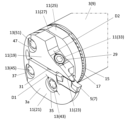
- FIG. 1 is a perspective view of a non-limiting one-sided cutting tool of the present disclosure
- FIG. FIG. 2 is an enlarged view of region II shown in FIG. 1
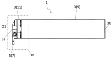
- FIG. 2 is a side view of the cutting tool shown in FIG. 1
- 4 is an enlarged view of region IV shown in FIG. 3.
- FIG. It is an exploded perspective view of the cutting insert, the 2nd member, and the clamp screw in the cutting tool shown in FIG.
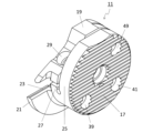
- FIG. 2 is a perspective view of the second member of the cutting tool shown in FIG. 1 viewed from the tip side.
- FIG. 7 is a perspective view of the second member shown in FIG. 6 viewed from the rear end side.
- FIG. 7 is a plan view of the second member shown in FIG. 6 viewed from the tip side.
- FIG. 7 is a plan view of the second member shown in FIG. 6 viewed from the rear end side.
- FIG. 9 is a side view of the second member shown in FIG. 8 when viewed from the X direction.
- FIG. 9 is a side view of the second member shown in FIG. 8 when viewed from the XI direction.
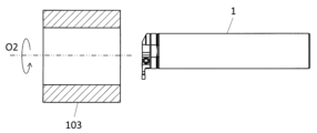
- 1 is a schematic diagram illustrating a step in a non-limiting method of manufacturing a cut piece of the present disclosure
- FIG. 1 is a schematic diagram illustrating a step in a non-limiting method of manufacturing a cut piece of the present disclosure
- FIG. 1 is a schematic diagram illustrating a step in a non-limiting method of manufacturing a cut piece of the present disclosure
- FIG. 1 is a schematic diagram illustrating a step in a non-limiting method of manufacturing a cut piece of the present disclosure
- FIG. 1 is a schematic diagram illustrating a step in a non-limiting method of manufacturing a cut piece of the present disclosure
- FIG. 1 is a schematic diagram illustrating a
- ⁇ Cutting tools> a non-limiting one-sided cutting tool 1 of the present disclosure will be described in detail using the drawings.
- the cutting tool 1 may include any constituent members not shown in the respective figures referred to.
- the dimensions of the members in each figure do not faithfully represent the dimensions of the actual constituent members or the dimensional ratios of each member.
- the cutting tool 1 may include a holder 3 and a cutting insert 5, as in a non-limiting example shown in FIGS. 1 to 11.
- the holder 3 may be rod-shaped.
- the holder 3 may have a cylindrical shape.
- the cylindrical shape may be any approximately cylindrical shape, and does not need to be a cylindrical shape in the strict sense.
- the holder 3 may extend from the front end 3a toward the rear end 3b.
- the holder 3 may extend along the central axis O1 from the front end 3a toward the rear end 3b.
- the holder 3 is not limited to a specific size.
- the length of the holder 3 in the direction along the central axis O1 may be set to about 150 to 450 mm.
- the width (diameter) of the holder 3 in the direction orthogonal to the central axis O1 may be set to about 10 to 50 mm.
- the cutting insert 5 may simply be called an insert 5.
- the insert 5 can be used to cut a workpiece during cutting.
- the insert 5 may have a columnar shape.
- the insert 5 may have a prismatic shape.
- the prismatic shape may be approximately a prismatic shape, and does not need to be a prismatic shape in a strict sense.
- the insert 5 may have a cutting edge 7.
- the cutting edge 7 may be located at the end of the insert 5 in the longitudinal direction.
- the insert 5 may be attached to the tip 3a of the holder 3.
- the insert 5 may be attached to the holder 3 such that the cutting edge 7 protrudes laterally at the tip 3a of the holder 3.
- the cutting tool 1 can perform cutting by bringing the cutting blade 7 into contact with a workpiece.
- the cutting edge 7 may be positioned farthest from the central axis O1 at the tip 3a of the holder 3. When the cutting edge 7 protrudes laterally in this way, it is possible to bring only the vicinity of the cutting edge 7 into contact with the workpiece.
- the holder 3 may be composed of multiple members.
- the holder 3 may include a first member 9, a second member 11, and a fixing screw 13, as in a non-limiting example shown in FIG.
- the first member 9 may be rod-shaped. Further, the first member 9 may be located on the rear end 3b side and have a first uneven surface 15 on the front end 3a side (see FIGS. 2 and 4). The first member 9 can function as a member gripped by a machine tool. The first member 9 may also be called a shank.
- the first uneven surface 15 may be composed of, for example, a plurality of grooves extending parallel to each other.
- the direction in which the plurality of grooves on the first uneven surface 15 extend may be the same as the direction in which the cutting edge 7 of the insert 5 projects.
- the direction in which the cutting edge 7 of the insert 5 projects may be referred to as the longitudinal direction of the insert 5.
- the depths of the plurality of grooves on the first uneven surface 15 may be the same or different from each other.
- the second member 11 may have a second uneven surface 17 located on the front end 3a side and fitted to the first uneven surface 15 on the rear end 3b side.
- the second member 11 can function as a member that fixes the insert 5.
- the second member 11 may also be called a head.
- the second member 11 may have a plate shape.
- the second uneven surface 17 may be composed of, for example, a plurality of grooves extending parallel to each other.
- the direction in which the plurality of grooves on the second uneven surface 17 extend may be the same as the direction in which the cutting edge 7 of the insert 5 projects.
- the plurality of grooves on the first uneven surface 15 and the plurality of grooves on the second uneven surface 17 are configured to mesh with each other. They may be fitted together.
- the depths of the plurality of grooves on the second uneven surface 17 may be the same or different from each other.
- the first uneven surface 15 and the second uneven surface 17 in a non-limiting example shown in FIG. 2 etc. may also be called serrations.
- Serrations may refer to sawtooth-shaped irregularities formed by a plurality of grooves extending in parallel.
- the fixing screw 13 may be a member that fixes the second member 11 to the first member 9. There may be only one fixing screw 13, or there may be a plurality of fixing screws 13.
- the second member 11 may have an upper jaw part 19, a lower jaw part 21, a pocket 23, a connecting part 25, and a slit 27, as shown in a non-limiting example shown in FIGS. 6 and 7.
- the upper jaw portion 19 may be located on the side of the tip 3a of the second member 11.
- the lower jaw portion 21 may be located on the side of the tip 3a of the second member 11, or may face the upper jaw portion 19.
- the upper jaw part 19 and the lower jaw part 21 can come into contact with the insert 5 when the insert 5 is attached to the holder 3, and can sandwich the insert 5, as shown in a non-limiting example shown in FIG. be.
- upper jaw part 19 and the lower jaw part 21 are expressions for convenience and do not indicate the directionality of upper and lower.
- the upper jaw 19 does not need to face upward when the cutting tool 1 is used.
- the pocket 23 may be located between the upper jaw part 19 and the lower jaw part 21.
- the insert 5 can be attached to the pocket 23. By inserting the insert 5 into the pocket 23 and bringing the upper jaw part 19 and the lower jaw part 21 into contact with the insert 5, it is possible to grip the insert 5 with the upper jaw part 19 and the lower jaw part 21.
- first uneven surface 15 and the second uneven surface 17 are each constituted by a plurality of grooves extending parallel to each other, even if these plural grooves extend parallel to the pocket 23, good.
- the holding force of the plurality of grooves against the largest principal force among the cutting loads applied to the cutting tool 1 during cutting is increased.
- parallel here does not require strictness, and allows the plurality of grooves to be slightly inclined (approximately 5 degrees) with respect to the pocket 23.
- the connecting portion 25 may be located on the rear end 3b side of the second member 11, and may include the second uneven surface 17.
- the connecting portion 25 can function as a portion that connects the second member 11 to the first member 9.
- the slit 27 may be located between the upper jaw portion 19 and the connecting portion 25.
- the lower jaw portion 21 may be fixed to the connecting portion 25.
- the upper jaw portion 19 may be separated from the connecting portion 25 via the slit 27. This makes it easier for the upper jaw portion 19 to move in the vertical direction, making it easier to attach and detach the insert 5.
- the slit 27 may be located only between the upper jaw part 19 and the connecting part 25, or as shown in FIG. may be located.
- the process of forming the slit 27 is facilitated.
- the upper jaw portion 19 may have an upper through hole 29, as in a non-limiting example shown in FIG.
- the upper through hole 29 may open toward the lower jaw portion 21.
- the lower jaw portion 21 may have a screw hole 31.
- the screw hole 31 may open toward the upper through hole 29.
- the second member 11 may further include a clamp screw 33, as in a non-limiting example shown in FIG.
- the clamp screw 33 may be inserted into the upper through hole 29 and the screw hole 31.
- the clamp screw 33 may be a member that fixes the upper jaw part 19 to the lower jaw part 21.
- the insert 5 can be fixed to the pocket 23 by tightening the clamp screw 33 inserted into the upper through hole 29 and the screw hole 31. That is, the clamp screw 33 is tightened while the insert 5 is gripped by the upper jaw part 19 and the lower jaw part 21, and the insert 5 is placed in the pocket 23 by the clamping force obtained when the upper jaw part 19 is elastically deformed and pushed down. It becomes possible to fix it. Further, by tightening the clamp screw 33, it is also possible to adjust the clamping force.
- the clamp screw 33 may be inserted into the upper through hole 29 and the screw hole 31 so as to intersect with the central axis O1 (see FIG. 8). In this case, it is easy to increase the length of the portion formed by the upper through hole 29 and the screw hole 31 into which the clamp screw 33 is inserted. Therefore, it becomes possible to increase the restraining force of the insert 5 by the clamp screw 33.
- the lower jaw portion 21 may further include a first through hole 35 and a second through hole 37, as in a non-limiting example shown in FIG.
- the first through hole 35 and the second through hole 37 may each extend from the leading end 3a toward the rear end 3b.
- the connecting portion 25 may have a third through hole 39 and a fourth through hole 41, as in a non-limiting example shown in FIG.
- the third through hole 39 may open toward the first through hole 35.
- the fourth through hole 41 may open toward the second through hole 37.
- the third through hole 39 may be connected to the first through hole 35, and the fourth through hole 41 may be connected to the second through hole 37.
- the fixing screw 13 may include a first fixing screw 43 and a second fixing screw 45, as in a non-limiting example shown in FIG.
- the first fixing screw 43 may be inserted into the first through hole 35 and the third through hole 39.
- the second fixing screw 45 may be inserted into the second through hole 37 and the fourth through hole 41.
- the screw hole 31 may extend between the first through hole 35 and the second through hole 37, as in a non-limiting example shown in FIG. In this case, it is easy to increase the length of the screw hole 31. Therefore, it is easy to ensure clamping force.
- the same member as the clamp screw 33 may be used as the first fixing screw 43 and the second fixing screw 45, or different members may be used.
- the diameter D1 of the first fixing screw 43 and the second fixing screw 45 may be larger than the diameter D2 of the clamp screw 33. Since the diameter D2 of the clamp screw 33 is relatively small (thin), the strength of the upper jaw portion 19 can be easily ensured. Further, since the diameter D1 of the first fixing screw 43 and the second fixing screw 45 is relatively large (thick), the second member 11 can be firmly fixed to the first member 9.
- the upper jaw portion 19 may further include a fifth through hole 47 extending from the distal end 3a toward the rear end 3b, as shown in a non-limiting example shown in FIG.
- the connecting portion 25 may further include a sixth through hole 49 that opens toward the fifth through hole 47, as in a non-limiting example shown in FIG.
- the fixing screw 13 may further include a third fixing screw 51 inserted into the fifth through hole 47 and the sixth through hole 49, as in a non-limiting example shown in FIG. In these cases, the fixed state of the second member 11 to the first member 9 is likely to be stable.
- the sixth through hole 49 may be connected to the fifth through hole 47.
- the second through hole 37 and the fifth through hole 47 may be located closer to the pocket 23 than the portion where the upper jaw portion 19 and the lower jaw portion 21 are connected.
- the cutting load applied to the clamp screw 33 and the portion where the upper jaw part 19 and the lower jaw part 21 are connected can be distributed to the second fixing screw 45 and the third fixing screw 51. Therefore, it becomes possible to improve the durability of the holder 3.
- the width W1 of the upper jaw part 19 and the width W2 of the connecting part 25 may each be larger than the width W0 of the slit 27. In this case, the rigidity of the upper jaw portion 19 and the connecting portion 25 can be easily maintained. Therefore, the rigidity of the second member 11 is easily ensured.
- the width W1 of the upper jaw portion 19 may be the same as the width W2 of the connecting portion 25, or may be different. For example, as in a non-limiting example shown in FIG. 10, the width W1 of the upper jaw portion 19 may be larger than the width W2 of the connecting portion 25. In this case, the rigidity of the upper jaw portion 19 can be easily maintained. Therefore, clamping force can be easily ensured.
- the width W1 of the upper jaw portion 19 and the width W2 of the connecting portion 25 are not limited to specific sizes.
- the width W1 may be set to about 5 to 10 mm.
- the width W2 may be set to about 5 to 10 mm.
- the width W1 may be evaluated using the maximum value.
- the width W2 may be evaluated using the maximum value at a portion facing the upper jaw portion 19.
- the bottom surface 53 of the slit 27 may extend parallel to the pocket 23, as in the non-limiting example shown in FIGS. 8 and 10.
- the upper jaw part 19 can be easily moved in the vertical direction with respect to the lower jaw part 21, and the thickness of the second member 11 in the vertical direction near the boundary between the lower jaw part 21 and the connecting part 25 can be ensured.
- easy to be As a result, the insert 5 can be easily attached to the pocket 23, and the strength of the second member 11 can be easily ensured.
- parallel is not limited to strict parallelism, but may also mean allowing an inclination of approximately ⁇ 5°.
- the respective unevenness on the first uneven surface 15 and the second uneven surface 17 may extend parallel to the pocket 23.
- the plurality of grooves in the first uneven surface 15 and the second uneven surface 17 may extend parallel to the pocket 23, as in a non-limiting example shown in FIGS. 2 and 7.
- a relatively large cutting load is likely to be applied in a direction perpendicular to the pocket 23.
- the relatively large cutting load described above is likely to be received by the first uneven surface 15 and the second uneven surface 17. Therefore, the durability of the holder 3 is high.
- the lower jaw portion 21 may be formed integrally with the connecting portion 25, as in a non-limiting example shown in FIG. In this case, the strength of the second member 11 is high.
- the connecting portion 25 may overlap at least a portion of the upper jaw portion 19 when viewed from the rear end 3b side (see FIG. 9). Further, the second uneven surface 17 may overlap at least a portion of the upper jaw portion 19 when viewed from the rear end 3b side (see FIG. 9).
- Examples of the material of the holder 3 include steel and cast iron. When the material of the holder 3 is steel, the holder 3 has high toughness.
- Examples of the material of the insert 5 include cemented carbide and cermet.
- Compositions of the cemented carbide may include, for example, WC-Co, WC-TiC-Co and WC-TiC-TaC-Co.
- WC, TiC, and TaC may be hard particles
- Co may be a binder phase.
- the cermet may be a sintered composite material in which a metal is combined with a ceramic component.
- cermets include titanium compounds containing titanium carbide (TiC) or titanium nitride (TiN) as a main component. It goes without saying that the material of the insert 5 is not limited to the above composition.
- the surface of the insert 5 may be coated with a coating using chemical vapor deposition (CVD) or physical vapor deposition (PVD) methods.
- CVD chemical vapor deposition
- PVD physical vapor deposition
- the composition of the coating include titanium carbide (TiC), titanium nitride (TiN), titanium carbonitride (TiCN), and alumina (Al 2 O 3 ).
- the cut workpiece 101 may be produced by cutting a workpiece 103.
- the method for manufacturing the cut workpiece 101 may include the following steps. That is, (1) A step of rotating the work material 103; (2) a step of bringing the cutting tool 1 represented by the above-mentioned non-limiting embodiment into contact with the rotating workpiece 103; (3) a step of separating the cutting tool 1 from the workpiece 103; may be provided.
- the workpiece 103 is rotated around the axis O2, and the cutting tool 1 is moved relatively close to the workpiece 103. good.
- the insert 5 (cutting blade 7) of the cutting tool 1 may be brought into contact with the workpiece 103 to cut the workpiece 103.
- the cutting tool 1 may be moved relatively away from the workpiece 103.
- the cutting tool 1 in each step, is brought into contact with the work material 103 by moving the cutting tool 1, or the cutting tool 1 is removed from the work material 103. Although they are separated from each other, they are of course not limited to this form.
- the workpiece 103 may be brought closer to the cutting tool 1.
- the workpiece 103 may be moved away from the cutting tool 1.
- the workpiece 103 may be kept in a rotated state and the process of bringing the insert 5 (cutting blade 7) of the cutting tool 1 into contact with different parts of the workpiece 103 may be repeated. good.
- Examples of the material of the work material 103 include carbon steel, alloy steel, stainless steel, cast iron, and non-ferrous metals.
Landscapes
- Engineering & Computer Science (AREA)
- Mechanical Engineering (AREA)
- Cutting Tools, Boring Holders, And Turrets (AREA)
Priority Applications (1)
| Application Number | Priority Date | Filing Date | Title |
|---|---|---|---|
| JP2024507700A JP7756789B2 (ja) | 2022-03-14 | 2023-03-01 | 切削工具及び切削加工物の製造方法 |
Applications Claiming Priority (2)
| Application Number | Priority Date | Filing Date | Title |
|---|---|---|---|
| JP2022038894 | 2022-03-14 | ||
| JP2022-038894 | 2022-03-14 |
Publications (1)
| Publication Number | Publication Date |
|---|---|
| WO2023176441A1 true WO2023176441A1 (ja) | 2023-09-21 |
Family
ID=88023558
Family Applications (1)
| Application Number | Title | Priority Date | Filing Date |
|---|---|---|---|
| PCT/JP2023/007452 Ceased WO2023176441A1 (ja) | 2022-03-14 | 2023-03-01 | 切削工具及び切削加工物の製造方法 |
Country Status (2)
| Country | Link |
|---|---|
| JP (1) | JP7756789B2 (https=) |
| WO (1) | WO2023176441A1 (https=) |
Cited By (1)
| Publication number | Priority date | Publication date | Assignee | Title |
|---|---|---|---|---|
| JP7788094B1 (ja) * | 2025-09-03 | 2025-12-18 | 株式会社タンガロイ | 工具ボディとそれを含む切削工具 |
Citations (4)
| Publication number | Priority date | Publication date | Assignee | Title |
|---|---|---|---|---|
| KR20090008596A (ko) * | 2007-07-18 | 2009-01-22 | 대구텍 주식회사 | 모듈형 툴 조립체 |
| WO2011074571A1 (ja) * | 2009-12-14 | 2011-06-23 | 京セラ株式会社 | 切削工具用ホルダおよび切削工具、並びにそれを用いた切削加工物の製造方法 |
| JP2013237153A (ja) * | 2013-09-03 | 2013-11-28 | Mitsubishi Materials Corp | 内径加工工具および内径加工方法 |
| WO2021260676A1 (en) * | 2020-06-23 | 2021-12-30 | Iscar Ltd. | Tool adaptor having an insert receiving pocket and a fastening bore, and cutting tool assembly |
Family Cites Families (2)
| Publication number | Priority date | Publication date | Assignee | Title |
|---|---|---|---|---|
| SE525462C2 (sv) * | 2002-06-18 | 2005-02-22 | Sandvik Ab | Verktygshuvud för spånavskiljande metallbearbetningsverktyg med spännskruv vilken ingängas i en mutterrulle |
| SE526536C2 (sv) * | 2003-11-19 | 2005-10-04 | Sandvik Intellectual Property | Verktygshuvud med spännanordning i form av en mutterrulle verkande i en slits |
-
2023
- 2023-03-01 WO PCT/JP2023/007452 patent/WO2023176441A1/ja not_active Ceased
- 2023-03-01 JP JP2024507700A patent/JP7756789B2/ja active Active
Patent Citations (4)
| Publication number | Priority date | Publication date | Assignee | Title |
|---|---|---|---|---|
| KR20090008596A (ko) * | 2007-07-18 | 2009-01-22 | 대구텍 주식회사 | 모듈형 툴 조립체 |
| WO2011074571A1 (ja) * | 2009-12-14 | 2011-06-23 | 京セラ株式会社 | 切削工具用ホルダおよび切削工具、並びにそれを用いた切削加工物の製造方法 |
| JP2013237153A (ja) * | 2013-09-03 | 2013-11-28 | Mitsubishi Materials Corp | 内径加工工具および内径加工方法 |
| WO2021260676A1 (en) * | 2020-06-23 | 2021-12-30 | Iscar Ltd. | Tool adaptor having an insert receiving pocket and a fastening bore, and cutting tool assembly |
Cited By (1)
| Publication number | Priority date | Publication date | Assignee | Title |
|---|---|---|---|---|
| JP7788094B1 (ja) * | 2025-09-03 | 2025-12-18 | 株式会社タンガロイ | 工具ボディとそれを含む切削工具 |
Also Published As
| Publication number | Publication date |
|---|---|
| JPWO2023176441A1 (https=) | 2023-09-21 |
| JP7756789B2 (ja) | 2025-10-20 |
Similar Documents
| Publication | Publication Date | Title |
|---|---|---|
| JPWO2012086375A1 (ja) | 切削工具およびそれを用いた切削加工物の製造方法 | |
| JP6272457B2 (ja) | 切削インサート、切削工具及び切削加工物の製造方法 | |
| JP7757411B2 (ja) | 切削工具、及び切削加工物の製造方法 | |
| JP5528264B2 (ja) | 切削工具および切削工具を用いた被削材の切削方法 | |
| JP7128185B2 (ja) | 切削インサート、切削工具及び切削加工物の製造方法 | |
| JP7756789B2 (ja) | 切削工具及び切削加工物の製造方法 | |
| JP7368064B2 (ja) | 工作機械及び切削加工物の製造方法 | |
| JP7102283B2 (ja) | ホルダ、切削工具及び切削加工物の製造方法 | |
| JP7114733B2 (ja) | 切削インサート、切削工具及び切削加工物の製造方法 | |
| JP7727750B2 (ja) | 切削工具及び切削加工物の製造方法 | |
| JP7592867B2 (ja) | 切削インサート、切削工具及び切削加工物の製造方法 | |
| JP7594672B2 (ja) | 切削インサート、切削工具及び切削加工物の製造方法 | |
| JP7257413B2 (ja) | 切削インサート、切削工具及び切削加工物の製造方法 | |
| JP7818091B2 (ja) | 切削ユニット、切削工具、刃物台、及び切削加工物の製造方法 | |
| JP7711205B2 (ja) | ホルダ、切削工具、及び切削加工物の製造方法 | |
| JP7344385B2 (ja) | 切削インサート、切削工具及び切削加工物の製造方法 | |
| JP6418765B2 (ja) | 切削インサート、切削工具および切削加工物の製造方法 | |
| JP7117389B2 (ja) | 切削インサート、切削工具及び切削加工物の製造方法 | |
| JP7527489B2 (ja) | ホルダ、切削工具及び切削加工物の製造方法 | |
| JP7223773B2 (ja) | 回転工具及び切削加工物の製造方法 | |
| CN113795344B (zh) | 夹紧构件、机床以及切削加工物的制造方法 | |
| CN113474109B (zh) | 切削刀片、切削刀具及切削加工物的制造方法 | |
| JP2020172005A (ja) | 切削インサート、切削工具、及び切削加工物の製造方法 | |
| WO2024224816A1 (ja) | 切削インサート、切削工具及び切削加工物の製造方法 | |
| WO2025154369A1 (ja) | 切削工具、及び切削加工物の製造方法 |
Legal Events
| Date | Code | Title | Description |
|---|---|---|---|
| 121 | Ep: the epo has been informed by wipo that ep was designated in this application |
Ref document number: 23770399 Country of ref document: EP Kind code of ref document: A1 |
|
| ENP | Entry into the national phase |
Ref document number: 2024507700 Country of ref document: JP Kind code of ref document: A |
|
| NENP | Non-entry into the national phase |
Ref country code: DE |
|
| 122 | Ep: pct application non-entry in european phase |
Ref document number: 23770399 Country of ref document: EP Kind code of ref document: A1 |