WO2023176333A1 - テーパーリング素材の製造方法 - Google Patents
テーパーリング素材の製造方法 Download PDFInfo
- Publication number
- WO2023176333A1 WO2023176333A1 PCT/JP2023/006262 JP2023006262W WO2023176333A1 WO 2023176333 A1 WO2023176333 A1 WO 2023176333A1 JP 2023006262 W JP2023006262 W JP 2023006262W WO 2023176333 A1 WO2023176333 A1 WO 2023176333A1
- Authority
- WO
- WIPO (PCT)
- Prior art keywords
- ring material
- less
- tapered
- drawing process
- temperature
- Prior art date
- Legal status (The legal status is an assumption and is not a legal conclusion. Google has not performed a legal analysis and makes no representation as to the accuracy of the status listed.)
- Ceased
Links
Images


Classifications
-
- B—PERFORMING OPERATIONS; TRANSPORTING
- B21—MECHANICAL METAL-WORKING WITHOUT ESSENTIALLY REMOVING MATERIAL; PUNCHING METAL
- B21D—WORKING OR PROCESSING OF SHEET METAL OR METAL TUBES, RODS OR PROFILES WITHOUT ESSENTIALLY REMOVING MATERIAL; PUNCHING METAL
- B21D53/00—Making other particular articles
- B21D53/92—Making other particular articles other parts for aircraft
-
- B—PERFORMING OPERATIONS; TRANSPORTING
- B21—MECHANICAL METAL-WORKING WITHOUT ESSENTIALLY REMOVING MATERIAL; PUNCHING METAL
- B21D—WORKING OR PROCESSING OF SHEET METAL OR METAL TUBES, RODS OR PROFILES WITHOUT ESSENTIALLY REMOVING MATERIAL; PUNCHING METAL
- B21D35/00—Combined processes according to or processes combined with methods covered by groups B21D1/00 - B21D31/00
- B21D35/002—Processes combined with methods covered by groups B21D1/00 - B21D31/00
- B21D35/005—Processes combined with methods covered by groups B21D1/00 - B21D31/00 characterized by the material of the blank or the workpiece
-
- B—PERFORMING OPERATIONS; TRANSPORTING
- B21—MECHANICAL METAL-WORKING WITHOUT ESSENTIALLY REMOVING MATERIAL; PUNCHING METAL
- B21D—WORKING OR PROCESSING OF SHEET METAL OR METAL TUBES, RODS OR PROFILES WITHOUT ESSENTIALLY REMOVING MATERIAL; PUNCHING METAL
- B21D22/00—Shaping without cutting, by stamping, spinning, or deep-drawing
- B21D22/02—Stamping using rigid devices or tools
- B21D22/022—Stamping using rigid devices or tools by heating the blank or stamping associated with heat treatment
-
- B—PERFORMING OPERATIONS; TRANSPORTING
- B21—MECHANICAL METAL-WORKING WITHOUT ESSENTIALLY REMOVING MATERIAL; PUNCHING METAL
- B21D—WORKING OR PROCESSING OF SHEET METAL OR METAL TUBES, RODS OR PROFILES WITHOUT ESSENTIALLY REMOVING MATERIAL; PUNCHING METAL
- B21D22/00—Shaping without cutting, by stamping, spinning, or deep-drawing
- B21D22/02—Stamping using rigid devices or tools
- B21D22/025—Stamping using rigid devices or tools for tubular articles
-
- B—PERFORMING OPERATIONS; TRANSPORTING
- B21—MECHANICAL METAL-WORKING WITHOUT ESSENTIALLY REMOVING MATERIAL; PUNCHING METAL
- B21D—WORKING OR PROCESSING OF SHEET METAL OR METAL TUBES, RODS OR PROFILES WITHOUT ESSENTIALLY REMOVING MATERIAL; PUNCHING METAL
- B21D41/00—Application of procedures in order to alter the diameter of tube ends
- B21D41/04—Reducing; Closing
-
- B—PERFORMING OPERATIONS; TRANSPORTING
- B21—MECHANICAL METAL-WORKING WITHOUT ESSENTIALLY REMOVING MATERIAL; PUNCHING METAL
- B21D—WORKING OR PROCESSING OF SHEET METAL OR METAL TUBES, RODS OR PROFILES WITHOUT ESSENTIALLY REMOVING MATERIAL; PUNCHING METAL
- B21D51/00—Making hollow objects
- B21D51/02—Making hollow objects characterised by the structure of the objects
- B21D51/10—Making hollow objects characterised by the structure of the objects conically or cylindrically shaped objects
-
- B—PERFORMING OPERATIONS; TRANSPORTING
- B21—MECHANICAL METAL-WORKING WITHOUT ESSENTIALLY REMOVING MATERIAL; PUNCHING METAL
- B21K—MAKING FORGED OR PRESSED METAL PRODUCTS, e.g. HORSE-SHOES, RIVETS, BOLTS OR WHEELS
- B21K21/00—Making hollow articles not covered by a single preceding sub-group
- B21K21/12—Shaping end portions of hollow articles
-
- C—CHEMISTRY; METALLURGY
- C21—METALLURGY OF IRON
- C21D—MODIFYING THE PHYSICAL STRUCTURE OF FERROUS METALS; GENERAL DEVICES FOR HEAT TREATMENT OF FERROUS OR NON-FERROUS METALS OR ALLOYS; MAKING METAL MALLEABLE, e.g. BY DECARBURISATION OR TEMPERING
- C21D9/00—Heat treatment, e.g. annealing, hardening, quenching or tempering, adapted for particular articles; Furnaces therefor
- C21D9/40—Heat treatment, e.g. annealing, hardening, quenching or tempering, adapted for particular articles; Furnaces therefor for rings; for bearing races
-
- C—CHEMISTRY; METALLURGY
- C22—METALLURGY; FERROUS OR NON-FERROUS ALLOYS; TREATMENT OF ALLOYS OR NON-FERROUS METALS
- C22F—CHANGING THE PHYSICAL STRUCTURE OF NON-FERROUS METALS AND NON-FERROUS ALLOYS
- C22F1/00—Changing the physical structure of non-ferrous metals or alloys by heat treatment or by hot or cold working
- C22F1/10—Changing the physical structure of non-ferrous metals or alloys by heat treatment or by hot or cold working of nickel or cobalt or alloys based thereon
-
- F—MECHANICAL ENGINEERING; LIGHTING; HEATING; WEAPONS; BLASTING
- F01—MACHINES OR ENGINES IN GENERAL; ENGINE PLANTS IN GENERAL; STEAM ENGINES
- F01D—NON-POSITIVE DISPLACEMENT MACHINES OR ENGINES, e.g. STEAM TURBINES
- F01D25/00—Component parts, details, or accessories, not provided for in, or of interest apart from, other groups
- F01D25/24—Casings; Casing parts, e.g. diaphragms, casing fastenings
-
- B—PERFORMING OPERATIONS; TRANSPORTING
- B64—AIRCRAFT; AVIATION; COSMONAUTICS
- B64F—GROUND OR AIRCRAFT-CARRIER-DECK INSTALLATIONS SPECIALLY ADAPTED FOR USE IN CONNECTION WITH AIRCRAFT; DESIGNING, MANUFACTURING, ASSEMBLING, CLEANING, MAINTAINING OR REPAIRING AIRCRAFT, NOT OTHERWISE PROVIDED FOR; HANDLING, TRANSPORTING, TESTING OR INSPECTING AIRCRAFT COMPONENTS, NOT OTHERWISE PROVIDED FOR
- B64F5/00—Designing, manufacturing, assembling, cleaning, maintaining or repairing aircraft, not otherwise provided for; Handling, transporting, testing or inspecting aircraft components, not otherwise provided for
- B64F5/10—Manufacturing or assembling aircraft, e.g. jigs therefor
-
- F—MECHANICAL ENGINEERING; LIGHTING; HEATING; WEAPONS; BLASTING
- F05—INDEXING SCHEMES RELATING TO ENGINES OR PUMPS IN VARIOUS SUBCLASSES OF CLASSES F01-F04
- F05D—INDEXING SCHEME FOR ASPECTS RELATING TO NON-POSITIVE-DISPLACEMENT MACHINES OR ENGINES, GAS-TURBINES OR JET-PROPULSION PLANTS
- F05D2230/00—Manufacture
- F05D2230/20—Manufacture essentially without removing material
-
- F—MECHANICAL ENGINEERING; LIGHTING; HEATING; WEAPONS; BLASTING
- F05—INDEXING SCHEMES RELATING TO ENGINES OR PUMPS IN VARIOUS SUBCLASSES OF CLASSES F01-F04
- F05D—INDEXING SCHEME FOR ASPECTS RELATING TO NON-POSITIVE-DISPLACEMENT MACHINES OR ENGINES, GAS-TURBINES OR JET-PROPULSION PLANTS
- F05D2240/00—Components
- F05D2240/10—Stators
- F05D2240/14—Casings or housings protecting or supporting assemblies within
-
- F—MECHANICAL ENGINEERING; LIGHTING; HEATING; WEAPONS; BLASTING
- F05—INDEXING SCHEMES RELATING TO ENGINES OR PUMPS IN VARIOUS SUBCLASSES OF CLASSES F01-F04
- F05D—INDEXING SCHEME FOR ASPECTS RELATING TO NON-POSITIVE-DISPLACEMENT MACHINES OR ENGINES, GAS-TURBINES OR JET-PROPULSION PLANTS
- F05D2300/00—Materials; Properties thereof
- F05D2300/10—Metals, alloys or intermetallic compounds
- F05D2300/17—Alloys
- F05D2300/172—Copper alloys
- F05D2300/1723—Nickel-Copper alloy, e.g. Monel
-
- F—MECHANICAL ENGINEERING; LIGHTING; HEATING; WEAPONS; BLASTING
- F05—INDEXING SCHEMES RELATING TO ENGINES OR PUMPS IN VARIOUS SUBCLASSES OF CLASSES F01-F04
- F05D—INDEXING SCHEME FOR ASPECTS RELATING TO NON-POSITIVE-DISPLACEMENT MACHINES OR ENGINES, GAS-TURBINES OR JET-PROPULSION PLANTS
- F05D2300/00—Materials; Properties thereof
- F05D2300/10—Metals, alloys or intermetallic compounds
- F05D2300/17—Alloys
- F05D2300/177—Ni - Si alloys
Definitions
- the present invention relates to a method for manufacturing a taper ring material, and more particularly, to a method for manufacturing a taper ring material in which a ring material made of a Ni-based superalloy is subjected to a mouth drawing process.
- Taper ring forging and mouth widening are processing methods that give a cylindrical ring material a tapered shape in which the diameter decreases toward one end in a partial range in the axial direction to create a tapered ring material. etc. are known.
- a core metal is inserted into a ring material, and an upper anvil placed above the ring material is used to reduce the outer surface of the ring material in its entire axial direction, while rotating the ring material to move the area of reduction.
- This is a processing method that repeatedly gives a tapered shape. Mouth widening is a processing method in which a punch is pushed into one end of the ring material to enlarge the diameter of this end, thereby giving it a tapered shape.
- mouth drawing is known as a processing method for imparting a tapered shape to the ring material.
- Mouth drawing is a processing method in which a die with a tapered inner surface is pressed against one end of a ring material to reduce the diameter of this end and give the ring material a tapered shape.
- Patent Document 1 describes tapered ring forging and mouth drawing as conventional techniques, and it has been pointed out that tapered ring forging has problems such as difficulty in obtaining a desired shape and long forging time. There is. Furthermore, it has been pointed out that there is a problem in the mouth drawing process that the unprocessed cylindrical part bulges outward and the tapered part is folded. Therefore, in Patent Document 1, a cylindrical middle mold made of a plurality of block pieces is inserted into a ring material, and then a die rod is press-fitted into the tapered inner surface of the middle mold. It is described that the ring material expands in the radial direction to enlarge the diameter of the ring material and give it a tapered shape.
- Patent Document 2 points out that although the mouth drawing process is advantageous in terms of working time, the deformation is gradual and there are problems in that the tapered shape may shift in position and the radius of curvature cannot be made small.
- the edge region of the ring material is subjected to thinning treatment, or the region is notched in the circumferential direction, and the opening is drawn, thereby reducing the deviation in the position of the tapered shape. It is also described that the radius of curvature can be made small.
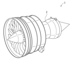
- Examples of uses for the tapered ring material include low-pressure turbine cases 2 of aircraft jet engines 1, as shown in FIG. 1, for example.
- the low-pressure turbine case 2 is very large, for example, with a diameter D of 500 to 2500 mm on the large diameter side and a height H of about 200 to 800 mm, and the taper angle of the tapered shape 11 is also compared.
- a tapered ring material 10 that is relatively large is used.
- the low-pressure turbine case 2 is exposed to high-temperature gas due to engine combustion, it needs to be made of a heat-resistant alloy.
- tapering material is used for turbine cases other than jet engines, it is also necessary to produce a large-sized tapering material made of heat-resistant alloy.
- As a heat-resistant alloy although Ni-based superalloys have excellent heat resistance, they have a problem in that they have high high-temperature strength and are difficult to plastically work, and the metals contained in the alloys are valuable and expensive.
- the present invention provides a method for manufacturing a tapered ring material that can give a tapered shape without causing forming defects even when a Ni-based superalloy ring material is subjected to a drawing process.
- the purpose is to provide.
- the method for manufacturing a tapered ring material according to the present invention includes pressing the inner surface of a die for mouth drawing having a taper on the inner surface so as to cover the entire circumference of the end of the ring material. This includes drawing a part of the peripheral surface of the ring material into a tapered shape along the inner surface of the die, the ring material being made of a Ni-based superalloy, and starting the drawing process.
- the temperature Tn (°C) of the peripheral surface of the ring material on which the opening drawing process is not performed is determined by the following formula 1 with respect to the solid solution temperature Ts (°C) of the precipitated phase of the Ni-based superalloy: Ts-300 ⁇ Tn ⁇ Ts-50 (Formula 1) It is characterized by satisfying the relationship.
- the ring material is processed according to the following formula 2: T 0 ⁇ Ts+30 (Formula 2) It may also include heating to a heating temperature T 0 (° C.) that satisfies the following relationship.
- the solid solution temperature Ts (°C) of the precipitated phase of the Ni-based superalloy may be within the range of 950°C to 1100°C.
- the temperature of the circumferential surface of the ring material on which the neck drawing process is performed when the neck drawing process is started may be equal to or higher than the temperature Tn of the circumferential surface of the ring material on which the neck drawing process is not performed.
- the ring material may have an outer diameter Da of 50 mm to 3000 mm and a height H 0 of 30 mm to 1000 mm.
- the tapered ring material may have an outer diameter Db on the small diameter side of 25 mm to 2850 mm.
- the ring material may have a wall thickness t 0 of 0.1 mm to 300 mm, and a wall thickness outer diameter ratio t 0 /Da of 0.001 to 0.1.
- the diameter reduction rate of the mouth drawing process may range from more than 0% to 50%.
- the taper ring material may have a taper angle ⁇ of 5° to 40°.
- the inner surface of the die for die drawing which has a taper on the inner surface may further include a restraining portion that covers a circumferential surface of the ring material on which the drawing process is not performed.
- the alloy composition of the Ni-based superalloy can be, for example, the following in mass %.
- Co 1% or less
- B 0.006% or less
- Cu 0.3% or less
- the balance being Fe and unavoidable impurities
- Al 2.0 to 4.0%
- Ti 2.0 to 4.0%
- Al + Ti 4.6 to 6.7%
- Mo more than 5.5 to 10 .0%
- W more than 0 to 4.0%
- B 0.001 to 0.040%
- C 0.02 to 0.06%
- Zr 0.05% or less
- Mg 0.005%
- P 0.01% or less
- Nb 1.0% or less
- Ta 1.0% or less
- Fe 2.0% or less
- the balance is Ni and inevitable impurities.
- the tapered ring material may be a material for an aircraft engine case.
- the temperature Tn of the circumferential surface of the ring material on which the mouth drawing process is not performed when starting the mouth drawing process is calculated using the above equation 1 with respect to the solid solution temperature Ts of the precipitated phase of the Ni-based superalloy.
- FIG. 2 is a perspective view schematically showing an example of the use of a tapered ring material.
- FIG. 2 is a perspective view schematically showing an example of a tapered ring material. It is a typical sectional view explaining an example of the mouth drawing process of the manufacturing method of the taper ring material concerning the present invention.
- FIG. 3 is a schematic cross-sectional view showing an example of molding defects that may occur during the mouth drawing process.
- FIG. 3 is a schematic cross-sectional view for explaining the dimensions and processing conditions of a tapered ring material.
- FIG. 3 is a cross-sectional view schematically showing another example of a die for mouth drawing used in the method for manufacturing a tapered ring material according to the present invention. It is a typical flow diagram explaining one embodiment of the manufacturing method of the taper ring material concerning the present invention.
- the method for manufacturing a tapered ring material according to the present embodiment includes at least a step of performing a mouth drawing process.
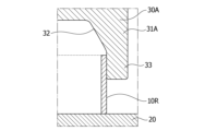
- the mouth drawing process uses, for example, a mouth drawing apparatus shown in FIG. 3.
- this mouth drawing processing device is equipped with a lower anvil 20 and a mouth drawing die 30 at positions sandwiching both ends of a ring material 10R having a cylindrical shape to be processed.
- An anvil (not shown) is provided.
- the mouth drawing die 30 has a cylindrical guide portion 31, and the inner surface of the guide portion 31 has a tapered inner diameter whose inner diameter gradually decreases from the tip toward the base end on the ring material 10R side. It has 32.
- the tapered shape of the inner surface portion 32 is formed to correspond to the desired tapered shape of the taper ring material.
- the mouth drawing die 30 is rolled down uniformly onto the ring material 10R in the direction of the arrow in FIG. 3(a).
- the entire circumference of the end of the ring material 10R on the side of the opening drawing die 30 is pushed so as to be covered by the tapered inner surface 32 of the opening drawing die 30, as shown in FIG. 3(b).
- the entire circumference is evenly compressed to the inner circumference.
- the end of the ring material 10R is formed into a desired tapered shape 11 along the inner surface 32 of the processing die 30, thereby forming a tapered ring. Material 10 can be obtained.
- the tapered ring material 10 thus obtained has a tapered portion 11 formed by the end drawing process and a cylindrical portion not subjected to the end drawing process, as shown by the dotted line in FIG. This is the ideal shape.
- the tapered ring material 10B is formed by mouth drawing, as shown by the solid line in FIG.
- a portion adjacent to the tapered portion 11 that should originally be cylindrical is bent and deformed toward the outer circumference, resulting in a molding defect 12.
- the periphery of the ring material 10R is not subjected to the drawing process when starting the drawing process.
- the temperature Tn (°C) of the surface 13 is set to the solid solution temperature Ts (°C) of the precipitated phase of the Ni-based superalloy, for example, the higher of the solid solution temperature of the ⁇ ' phase and the solid solution temperature of the ⁇ phase.
- Ts-300 ⁇ Tn ⁇ Ts-50 (Formula 1) Set the temperature to satisfy the relationship.
- the solid solution temperature of the ⁇ ' phase or ⁇ phase is the temperature at which the ⁇ ' phase or ⁇ phase dissolves in the matrix in the Ni-based superalloy. Although details will be described later, it is believed that the ⁇ ' phase or ⁇ phase, which depends on the composition of the Ni-based superalloy, contributes to suppressing coarsening of crystal grains.
- the Ni-based superalloy It is possible to increase the deformation resistance of the ring material 10R, so that even if a part of the circumferential surface of the ring material 10R is compressed inward by the mouth drawing die 30, the pressure by the mouth drawing die 30 can be increased. It is possible to prevent molding defects from occurring on the peripheral surface 13 of the portion that is not covered.
- the ring material 10R to be processed in the present invention is made of Ni-based superalloy.
- Ni-based superalloys are also called Ni-based heat-resistant alloys, and examples include Waspaloy (registered trademark) (UNS N07001) and Inconel (registered trademark) 718 (UNS N07718), but these are limited to specific products. However, any Ni-based superalloy can be widely applied to the present invention.
- UNS is the alloy number registered in the "Unified Numbering System" in the ASTM E527 and SAE J1086 standards.
- the alloy composition of Waspaloy is typically C: 0.02-0.10%, Mn: 0.1% or less, P: 0.015% or less, S: 0.015% or less, Si : 0.15% or less, Cr: 18-21%, Fe: 2% or less, Mo: 3.5-5.0%, Ti: 2.75-3.25%, Al: 1.2-1. 6%, Co: 12-15%, B: 0.003-0.01%, Cu: 0.1% or less, Zr: 0.02-0.08%, the remainder being Ni and unavoidable impurities. There is. Further, such an alloy composition may further contain 0.01% or less of Mg.
- the alloy composition of Inconel 718 is typically C: 0.08% or less, Mn: 0.35% or less, P: 0.015% or less, S: 0.015% or less, Si: 0. 35% or less, Cr: 17-21%, Ni: 50-55%, Mo: 2.8-3.3%, Nb and Ta: 4.75-5.5%, Ti: 0.65-1. 15%, Al: 0.2 to 0.8%, Co: 1% or less, B: 0.006% or less, Cu: 0.3% or less, and the remainder is Fe and unavoidable impurities.
- the Ni-based superalloy disclosed in Japanese Patent Application Laid-Open No. 2020-056103 by the applicant of this patent can also be used in the present invention, and the alloy composition is Co: 4.0 to 11.0 in mass%. %, Cr: 12.0-17.0%, Al: 2.0-4.0%, Ti: 2.0-4.0%, Al+Ti: 4.6-6.7%, Mo: 5.
- W More than 5 to 10.0%, W: more than 0 to 4.0%, B: 0.001 to 0.040%, C: 0.02 to 0.06%, Zr: 0.05% or less, Mg: 0.005% or less, P: 0.01% or less, Nb: 1.0% or less, Ta: 1.0% or less, Fe: 2.0% or less, and the remainder is Ni and unavoidable impurities.
- the solid solution temperature of the ⁇ ' phase or ⁇ phase of a Ni-based superalloy varies depending on the alloy composition, etc., and the solid solution temperature of the ⁇ ' phase or ⁇ phase of each alloy composition is published by academic literature and material manufacturers. Further, the solid solution temperature of the ⁇ ' phase or ⁇ phase can also be calculated using thermodynamic equilibrium software. For the solid solution temperature of the ⁇ ' phase or ⁇ phase of the Ni-based superalloy, such published values or calculated values can be used.
- the precipitated phase that suppresses the coarsening of crystal grains described above differs depending on the alloy composition of the Ni-based superalloy, but typically, the precipitated phase with a higher solid solution temperature of the ⁇ ' phase or ⁇ phase is the one that suppresses the coarsening of the crystal grains. have an effect.
- the ⁇ ' phase suppresses coarsening of crystal grains, and the solid solution temperature of the ⁇ ' phase is approximately 1020 to 1040°C.
- the ⁇ phase suppresses coarsening of crystal grains, and the solid solution temperature of the ⁇ phase is approximately 1000 to 1030°C.
- the temperature Ts is defined as the solid solution temperature of the precipitated phase that has the effect of suppressing coarsening of crystal grains.
- the solid solution temperature Ts of the precipitated phase ( ⁇ ' phase or ⁇ phase), which has the effect of suppressing grain coarsening, varies depending on the alloy composition, etc., it is typically within the range of approximately 800°C to 1200°C. It is preferable to use a Ni-based superalloy whose solid solution temperature Ts is within the range of 950°C to 1100°C.
- a more preferable temperature Tn of the circumferential surface 13 of the ring material 10R on which the opening drawing process is not performed when starting the opening drawing process is expressed by the following formula 1a: Ts-300 ⁇ Tn ⁇ Ts-80 (Formula 1a) This is the temperature that satisfies the relationship.
- the peripheral surface 14 on which the mouth drawing process is performed is heated. It may be covered with heat insulating material, etc.
- the ring material The opening drawing process can be started when the entire circumferential surface of the ring material 10R is at the same temperature, making it easy to control the temperature of the ring material 10R. Then, when starting the neck drawing process, is the temperature of the circumferential surface of the ring material 10R where the neck drawing process is performed the same as the temperature Tn of the circumferential surface of the ring material 10R where the neck drawing process is not performed? , or more.
- the diameter reduction rate is not particularly limited, but may range from more than 0% to 50%, or from more than 0% to 35%, for example. As shown in FIG. 5, the diameter reduction rate is expressed by the following formula from the outer diameter Da of the ring material 10R before the end drawing process and the outer diameter Db of the small diameter side of the tapered ring material 10 after the end drawing process.
- the outer diameter Da of the ring material 10R is not particularly limited, but may be, for example, 50 mm to 3000 mm, and when used for a pressure vessel or an aircraft engine case (turbine case), it may be 500 mm to 2500 mm. .
- the outer diameter Da of the ring material 10R may correspond to the outer diameter of the larger diameter side of the tapered ring material 10 after the mouth drawing process (FIG. 5). Then, the position of the outer diameter on the large diameter side is further processed, and for example, in a product such as a turbine case, it corresponds to the position of the diameter D on the large diameter side (FIG. 2).
- the outer diameter Db of the small diameter side of the tapered ring material 10 is not particularly limited, but may be, for example, 25 mm to 2850 mm, and may be 250 mm to 2375 mm when used for a pressure vessel or an aircraft engine case. .
- the height H 0 of the ring material 10R is not particularly limited, but may be, for example, 30 mm to 1000 mm, and when used for a pressure vessel or an aircraft engine case, it may be 200 mm to 800 mm.
- the wall thickness t 0 of the ring material 10R is not particularly limited, but may be, for example, from 0.1 mm to 300 mm, and when used for a pressure vessel or an aircraft engine case, may be from 2 mm to 125 mm.
- the wall thickness/outside diameter ratio t 0 /Da of the ring material 10R is not particularly limited, but may be, for example, 0.001 to 0.1, and when used for a pressure vessel or an aircraft engine case, 0. It may be 01 to 0.05.
- the height H 0 of the ring material 10R may vary slightly in the tapered ring material 10 after the mouth drawing process, depending on the taper angle ⁇ , etc., which will be described later (FIG. 5). Then, this tapered ring material is further processed and adjusted to the required height H for products such as aircraft engine cases, for example (FIG. 2).
- the taper angle ⁇ of the tapered ring material 10 is not particularly limited, and may be, for example, 5° to 40° or 10° to 30°. As shown in FIG. 5, the taper angle ⁇ is expressed as the angle of the outer peripheral surface of the tapered shape 11 portion of the tapered ring material 10 after the mouth drawing process with respect to the outer peripheral surface of the ring material 10R before the mouth drawing process.
- a lubricant to the outer peripheral surface of the ring material 10R. Furthermore, it is preferable to apply a lubricant to the inner surface of the die 30 for mouth drawing. In this way, by applying lubricant to the ring material 10R, the mouth drawing die 30, or both, the outer peripheral surface of the ring material 10R and the tapered inner surface 32 of the mouth drawing die 30 can be bonded. By reducing friction and reducing molding load, it is possible to prevent damage to the ring material 10R and the die 30 for mouth drawing, and to prevent formation defects during the mouth drawing process.
- the present invention is not limited to the mouth drawing process apparatus having such a configuration.
- the temperature Tn of the peripheral surface 13 of the ring material 10R on which the mouth drawing process is not performed is set to a temperature that satisfies the relationship of the above formula 1 with respect to the above solid solution temperature Ts of the Ni-based superalloy. If so, other mouth drawing devices may be used.
- the inner surface of the die 30A for edge drawing further includes a restraining portion 33 that covers the circumferential surface 13 of the ring material 10R on which the edge drawing is not performed. That is, as shown in FIG.
- the mouth drawing die 30A has a guide portion 31A that is a restraining portion whose inner surface extends perpendicularly to the lower anvil 20 so as to cover a position where forming defects occur in the taper ring material after processing. 33 may be used. With this configuration, the entire ring material 10R is restrained by the restraining portion 33 of the die 30A for mouth drawing, so it is possible to physically prevent the ring material 10R from expanding toward the outer circumference during the mouth drawing process. This makes it possible to more reliably prevent molding defects from occurring.
- the length of the restraining portion 33 in the vertical direction may be, for example, the length in the axial direction of the circumferential surface of the tapered ring material on which the opening drawing process is not performed.
- the method for manufacturing a tapered ring material according to the present embodiment may include a step of heating the ring material 10R before the above-mentioned mouth drawing process.
- the ring material 10R is heated using the following formula 2: T 0 ⁇ Ts+30 (Formula 2) It is preferable to heat to a heating temperature T 0 (° C.) that satisfies the following relationship.
- the heating temperature T0 of the ring material 10R is set to be higher than the temperature Tn of the circumferential surface 13 of the ring material 10R, which is not subjected to the drawing process, by, for example, 50°C or more when starting the drawing process.
- the temperature of the ring material 10R is lowered by cooling (air cooling), and the temperature of the circumferential surface 13 of the ring material 10R on which the neck drawing process is not performed can be set as the temperature Tn when the neck drawing process is started. .
- the heating temperature T0 is made higher than the above-mentioned solid solution temperature Ts+30, the conveyance time becomes longer, the temperature difference becomes larger between the surface of the ring material 10R and the center of the wall thickness, and a different metallographic structure occurs, resulting in the desired There is a possibility that it will not be able to demonstrate its characteristics.
- the ring material 10R is rapidly cooled, surface cracks may occur, so it is preferable to gradually lower the temperature by allowing it to cool during transportation. This can suppress surface cracks caused by rapid cooling, and reduce cracks caused by this. It is also possible to suppress the occurrence of forming defects during drawing.
- the method for manufacturing a tapered ring material according to the present embodiment may include other steps in addition to the above-mentioned opening drawing step and heating step.
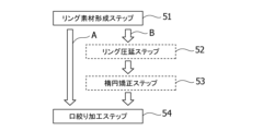
- the method for manufacturing a tapered ring material according to the present embodiment includes, for example, a ring material forming step 51 in which a ring material is obtained by forging or drilling a cylindrical material having a predetermined alloy composition; As shown in the arrow A shown in the figure, the ring material may be subjected to a drawing process to obtain a tapered ring material. Alternatively, as shown in the arrow B shown in the figure, the ring material forming step 51 may be included.
- a ring rolling step 52 in which the ring material is subjected to ring rolling
- an ellipse straightening step 53 in which the ellipse of the ring material thus rolled is corrected, and a tapered ring material is formed from the ring material whose ellipse has been corrected in this way by a mouth drawing process. It may also include a mouth drawing step 54 to obtain. Further, steps other than those described above may be further included; for example, the above-described heating step (not shown) may be performed between the ellipse correction step 53 and the mouth drawing step 54. Furthermore, either the ring rolling step 52 or the ellipse straightening step 53 may be used.
- the ring material forming step 51 is a step that is normally adopted to obtain a ring material, so a detailed explanation will be omitted here.
- a cylindrical ring material can be obtained by obtaining a shaped billet and subjecting it to a forging process, a drilling process, etc. Note that after the drilling process, the diameter may be expanded in a ring forging process or the like to obtain a ring material with predetermined dimensions.
- the ring rolling step 52 is not an essential step, if there are variations in the thickness of the ring material in the circumferential direction, wrinkles and eccentricity are likely to occur in the mouth drawing step 54, and also due to uneven loads. Molding defects are also more likely to occur. Therefore, before the mouth drawing step 54, the ring material is ring-rolled using a ring rolling device in the ring rolling step 52 to make the wall thickness of the ring material uniform. The occurrence of molding defects, wrinkles, and eccentricity can be suppressed.
- the ellipse correction step 53 is not an essential step, if the ring material is elliptical, forming defects, wrinkles, and eccentricity are likely to occur in the mouth drawing step 54. Therefore, by correcting the ellipse of the ring material using an expander or the like in the ellipse correction step 53 before the mouth drawing step 54, the occurrence of forming defects, wrinkles, and eccentricity in the mouth drawing step 54 can be avoided. Can be suppressed.
- the ring material is also corrected in oval and dimension by other machining or by combining the expander and other machining. , the ellipse of the ring material may be corrected.
- a taper ring material that can be used for applications such as aircraft engine cases can be manufactured from a Ni-based superalloy ring material. be able to.
- the ring material was made.
- a die for mouth drawing having a taper shape corresponding to the taper angle ⁇ of the taper ring material was 30°.
- the ring material After heating the ring material in a heating furnace to a heating temperature T0 of 1030°C, it was transported from the heating furnace and placed on the lower anvil of the mouth drawing machine, so that the peripheral surface temperature of the ring material decreased to 940°C. After confirming this, the ring material was pressed against the ring material to start drawing. Then, the opening drawing process was completed by pressing down the opening drawing die until the diameter reduction rate reached 30% (that is, the reduced outer diameter Db was 420 mm) (Example 1). Note that the die for mouth drawing started the mouth drawing at room temperature.
- the peripheral surface of the tapered ring material thus obtained was inspected to see if any molding defects, such as bending and deformation toward the outer periphery, had occurred.
- To inspect for molding defects measure the outer diameter of the undrawn peripheral surface of the tapered ring material, and if it increases by 1.5% or more than the outer diameter of the original ring material, a molding defect has occurred. It was determined that As a result, no molding defects were observed in the tapered ring material of Example 1.
- a tapered ring material was obtained by drawing the ring material under the same conditions as in Example 1, except that the drawing process was started when the peripheral surface temperature of the ring material decreased to 900°C (Example 2, 3).
- Example 2, 3 the tapered ring materials of Examples 2 and 3 were examined for the occurrence of molding defects, no molding defects were confirmed.
- a tapered ring material was obtained by drawing the ring material under the same conditions as in Example 1, except that the drawing process was started when the peripheral surface temperature of the ring material dropped to 980°C ( comparative example).
- the tapered ring material of this comparative example was inspected for the occurrence of molding defects, it was confirmed that molding defects had occurred.
Landscapes
- Engineering & Computer Science (AREA)
- Mechanical Engineering (AREA)
- Chemical & Material Sciences (AREA)
- Physics & Mathematics (AREA)
- Thermal Sciences (AREA)
- Aviation & Aerospace Engineering (AREA)
- Materials Engineering (AREA)
- Metallurgy (AREA)
- Organic Chemistry (AREA)
- Crystallography & Structural Chemistry (AREA)
- General Engineering & Computer Science (AREA)
- Forging (AREA)
- Turbine Rotor Nozzle Sealing (AREA)
Priority Applications (5)
| Application Number | Priority Date | Filing Date | Title |
|---|---|---|---|
| US18/836,208 US20250114839A1 (en) | 2022-03-16 | 2023-02-21 | Tapered material manufacturing method |
| CN202380027175.9A CN118871223A (zh) | 2022-03-16 | 2023-02-21 | 锥形环原材料的制造方法 |
| EP23770292.3A EP4494776A4 (en) | 2022-03-16 | 2023-02-21 | Tapered material manufacturing method |
| MX2024010842A MX2024010842A (es) | 2022-03-16 | 2023-02-21 | Metodo para fabricar un material conico. |
| JP2023556859A JP7502727B2 (ja) | 2022-03-16 | 2023-02-21 | テーパーリング素材の製造方法 |
Applications Claiming Priority (2)
| Application Number | Priority Date | Filing Date | Title |
|---|---|---|---|
| JP2022041544 | 2022-03-16 | ||
| JP2022-041544 | 2022-03-16 |
Publications (1)
| Publication Number | Publication Date |
|---|---|
| WO2023176333A1 true WO2023176333A1 (ja) | 2023-09-21 |
Family
ID=88023378
Family Applications (1)
| Application Number | Title | Priority Date | Filing Date |
|---|---|---|---|
| PCT/JP2023/006262 Ceased WO2023176333A1 (ja) | 2022-03-16 | 2023-02-21 | テーパーリング素材の製造方法 |
Country Status (6)
| Country | Link |
|---|---|
| US (1) | US20250114839A1 (https=) |
| EP (1) | EP4494776A4 (https=) |
| JP (1) | JP7502727B2 (https=) |
| CN (1) | CN118871223A (https=) |
| MX (1) | MX2024010842A (https=) |
| WO (1) | WO2023176333A1 (https=) |
Citations (6)
| Publication number | Priority date | Publication date | Assignee | Title |
|---|---|---|---|---|
| JPS635843A (ja) | 1986-06-27 | 1988-01-11 | Kawasaki Steel Corp | 大型リングの口絞り鍛造方法 |
| JPS63317231A (ja) | 1987-06-22 | 1988-12-26 | Kawasaki Steel Corp | 鍛造リングの口絞り成形方法 |
| JP2018034201A (ja) * | 2016-09-02 | 2018-03-08 | 新日鐵住金株式会社 | 口絞り方法及び二相ステンレス鋼管の製造方法 |
| JP2019141864A (ja) * | 2018-02-19 | 2019-08-29 | 日本製鉄株式会社 | 二相ステンレス鋼管の口絞り加工方法及び二相ステンレス鋼管を生産する方法 |
| JP2020056103A (ja) | 2018-09-26 | 2020-04-09 | 日立金属株式会社 | 航空機エンジンケース用Ni基超耐熱合金及びこれからなる航空機エンジンケース |
| JP2020199516A (ja) * | 2019-06-07 | 2020-12-17 | 日本製鉄株式会社 | 端部が閉塞された管部材の製造方法 |
Family Cites Families (17)
| Publication number | Priority date | Publication date | Assignee | Title |
|---|---|---|---|---|
| US2357110A (en) * | 1941-09-15 | 1944-08-29 | Smith Corp A O | Method of making bombshells |
| JPH0661604B2 (ja) * | 1989-03-28 | 1994-08-17 | 川崎重工業株式会社 | 超耐熱合金製ディスクの製造方法 |
| ITVI20050010A1 (it) | 2005-01-17 | 2006-07-18 | I M Z Spa | Metodo per la fabbricazione di un elemento balistico inerte per esercitazioni ed elemento balistico inerte fabbricato con tale metodo |
| WO2008106858A1 (fr) * | 2007-03-05 | 2008-09-12 | Guizhou Anda Aviation Forging Co., Ltd. | Procédé de forgeage quasi-isothermique, à l'air, d'une pièce forgée en forme de disque de superalliages à base de nickel |
| CN101279349A (zh) * | 2008-04-23 | 2008-10-08 | 贵州航宇科技发展有限公司 | 镍基高温合金锥形环锻件的辗轧成形方法 |
| JP5180669B2 (ja) | 2008-05-07 | 2013-04-10 | 株式会社神戸製鋼所 | 口絞りシェルの製造方法 |
| FR2935623B1 (fr) * | 2008-09-05 | 2011-12-09 | Snecma | Procede de fabrication d'une piece thermomecanique de revolution circulaire comportant un substrat porteur a base de titane revetu d'acier ou superalliage, carter de compresseur de turbomachine resistant au feu de titane |
| CN102513442B (zh) * | 2011-11-24 | 2014-02-05 | 贵州安大航空锻造有限责任公司 | 高温合金矩形环轧件热胀形成形为异形环件的方法 |
| JP2014047389A (ja) * | 2012-08-31 | 2014-03-17 | Hitachi Ltd | 発電用ガスタービン用動翼と、熱処理方法 |
| JP6350919B2 (ja) * | 2013-03-21 | 2018-07-04 | 日立金属株式会社 | リング圧延用素材の製造方法 |
| JP6292761B2 (ja) * | 2013-03-28 | 2018-03-14 | 日立金属Mmcスーパーアロイ株式会社 | 環状成形体の製造方法 |
| FR3017060B1 (fr) * | 2014-02-05 | 2016-08-26 | Snecma | Outillage de forgeage pour la fabrication d'une couronne laminee de forme, notamment pour la fabrication d'un disque de turbomachine |
| MX375858B (es) * | 2014-09-01 | 2025-03-07 | Hitachi Metals Ltd | Metodo de fabricacion de articulo moldeado de anillo y material de anillo |
| CN109530607A (zh) * | 2018-12-28 | 2019-03-29 | 贵州航宇科技发展股份有限公司 | 一种718plus异形环锻件成形方法 |
| CN111112526A (zh) * | 2019-12-09 | 2020-05-08 | 贵州航宇科技发展股份有限公司 | In718合金轴向非对称多法兰机匣环件的制造方法 |
| US11951528B2 (en) * | 2020-08-20 | 2024-04-09 | Rolls-Royce Corporation | Controlled microstructure for superalloy components |
| CN112589021B (zh) * | 2020-11-17 | 2023-06-02 | 贵州航宇科技发展股份有限公司 | 一种in718合金双法兰高筒机匣环件的制造方法 |
-
2023
- 2023-02-21 WO PCT/JP2023/006262 patent/WO2023176333A1/ja not_active Ceased
- 2023-02-21 EP EP23770292.3A patent/EP4494776A4/en active Pending
- 2023-02-21 CN CN202380027175.9A patent/CN118871223A/zh active Pending
- 2023-02-21 JP JP2023556859A patent/JP7502727B2/ja active Active
- 2023-02-21 MX MX2024010842A patent/MX2024010842A/es unknown
- 2023-02-21 US US18/836,208 patent/US20250114839A1/en active Pending
Patent Citations (6)
| Publication number | Priority date | Publication date | Assignee | Title |
|---|---|---|---|---|
| JPS635843A (ja) | 1986-06-27 | 1988-01-11 | Kawasaki Steel Corp | 大型リングの口絞り鍛造方法 |
| JPS63317231A (ja) | 1987-06-22 | 1988-12-26 | Kawasaki Steel Corp | 鍛造リングの口絞り成形方法 |
| JP2018034201A (ja) * | 2016-09-02 | 2018-03-08 | 新日鐵住金株式会社 | 口絞り方法及び二相ステンレス鋼管の製造方法 |
| JP2019141864A (ja) * | 2018-02-19 | 2019-08-29 | 日本製鉄株式会社 | 二相ステンレス鋼管の口絞り加工方法及び二相ステンレス鋼管を生産する方法 |
| JP2020056103A (ja) | 2018-09-26 | 2020-04-09 | 日立金属株式会社 | 航空機エンジンケース用Ni基超耐熱合金及びこれからなる航空機エンジンケース |
| JP2020199516A (ja) * | 2019-06-07 | 2020-12-17 | 日本製鉄株式会社 | 端部が閉塞された管部材の製造方法 |
Non-Patent Citations (1)
| Title |
|---|
| See also references of EP4494776A4 |
Also Published As
| Publication number | Publication date |
|---|---|
| JPWO2023176333A1 (https=) | 2023-09-21 |
| EP4494776A1 (en) | 2025-01-22 |
| US20250114839A1 (en) | 2025-04-10 |
| MX2024010842A (es) | 2024-09-11 |
| EP4494776A4 (en) | 2026-03-04 |
| CN118871223A (zh) | 2024-10-29 |
| JP7502727B2 (ja) | 2024-06-19 |
Similar Documents
| Publication | Publication Date | Title |
|---|---|---|
| US11085104B2 (en) | Method for manufacturing Ni-based heat-resistant superalloy wire, and Ni-based heat-resistant super alloy wire | |
| US20200010930A1 (en) | Ni-based super heat-resistant alloy and method for manufacturing same | |
| KR101521039B1 (ko) | 단차가 형성된 단조재의 제조 방법 | |
| CN1329139C (zh) | 镍基超耐热合金在空气中的等温锻造方法 | |
| US20200377987A1 (en) | Method for manufacturing super-refractory nickel-based alloy and super-refractory nickel-based alloy | |
| CN105073295A (zh) | 环轧用材料 | |
| JP6738548B1 (ja) | Fe−Ni基超耐熱合金のリング圧延材の製造方法 | |
| US20020157740A1 (en) | Method for the treatment of metallic materials | |
| JP6454768B2 (ja) | チタン合金β鍛造材、および、超音波探傷検査方法 | |
| WO2025176040A1 (zh) | Gh4151合金棒材及其制备方法与应用 | |
| WO2013111768A1 (ja) | 熱間据込鍛造方法 | |
| CN113523163A (zh) | 核反应堆大规格镍基合金开坯锻造方法 | |
| JPH0692630B2 (ja) | 純チタンまたはチタン合金製継目無管の製造方法 | |
| JP2016007643A (ja) | チタン合金中間鍛造材、チタン合金中間鍛造材の形状決定方法、チタン合金β鍛造材の製造方法、チタン合金β鍛造材、および、超音波探傷検査方法 | |
| WO2020031579A1 (ja) | Ni基超耐熱合金の製造方法およびNi基超耐熱合金 | |
| JP7502727B2 (ja) | テーパーリング素材の製造方法 | |
| CN116274796A (zh) | 一种5b70铝合金高筒形环件锻造工艺 | |
| JP2019183263A (ja) | 冷間加工用Ni基超耐熱合金素材 | |
| JPH07223034A (ja) | チタン合金リングの製造方法 | |
| CN111872296B (zh) | 空心锻件芯轴拔长过程中的内孔偏心矫正方法 | |
| Esquivel et al. | Design, manufacturing and performance OF Fe–Mn–Si–Ni–Cr shape memory seamless couplings | |
| CN116200684B (zh) | 一种汽轮机用大规格锻件及其锻造方法 | |
| US6202281B1 (en) | Method for producing multilayer thin-walled bellows | |
| JP2018034201A (ja) | 口絞り方法及び二相ステンレス鋼管の製造方法 | |
| JP2000263105A (ja) | 鉄基分散強化型合金管の製造方法 |
Legal Events
| Date | Code | Title | Description |
|---|---|---|---|
| WWE | Wipo information: entry into national phase |
Ref document number: 2023556859 Country of ref document: JP |
|
| 121 | Ep: the epo has been informed by wipo that ep was designated in this application |
Ref document number: 23770292 Country of ref document: EP Kind code of ref document: A1 |
|
| WWE | Wipo information: entry into national phase |
Ref document number: 18836208 Country of ref document: US |
|
| WWE | Wipo information: entry into national phase |
Ref document number: MX/A/2024/010842 Country of ref document: MX |
|
| WWE | Wipo information: entry into national phase |
Ref document number: 202380027175.9 Country of ref document: CN |
|
| WWE | Wipo information: entry into national phase |
Ref document number: 2023770292 Country of ref document: EP |
|
| NENP | Non-entry into the national phase |
Ref country code: DE |
|
| ENP | Entry into the national phase |
Ref document number: 2023770292 Country of ref document: EP Effective date: 20241016 |
|
| WWP | Wipo information: published in national office |
Ref document number: 18836208 Country of ref document: US |