WO2023176306A1 - Label affixing device - Google Patents
Label affixing device Download PDFInfo
- Publication number
- WO2023176306A1 WO2023176306A1 PCT/JP2023/005695 JP2023005695W WO2023176306A1 WO 2023176306 A1 WO2023176306 A1 WO 2023176306A1 JP 2023005695 W JP2023005695 W JP 2023005695W WO 2023176306 A1 WO2023176306 A1 WO 2023176306A1
- Authority
- WO
- WIPO (PCT)
- Prior art keywords
- label
- belt
- conveyor belt
- article
- feeding
- Prior art date
Links
Images


Classifications
-
- B—PERFORMING OPERATIONS; TRANSPORTING
- B65—CONVEYING; PACKING; STORING; HANDLING THIN OR FILAMENTARY MATERIAL
- B65C—LABELLING OR TAGGING MACHINES, APPARATUS, OR PROCESSES
- B65C9/00—Details of labelling machines or apparatus
- B65C9/40—Controls; Safety devices
- B65C9/42—Label feed control
Definitions
- the present invention relates to a label affixing device for affixing labels to transported articles.
- Patent Document 1 European Patent Application Publication No. 3404644
- Patent Document 1 describes an activation mechanism that activates an adhesive layer included in a label, a feeding mechanism that feeds out a label to the activation mechanism, and an activation mechanism that feeds out a label to the activation mechanism.
- a labeling apparatus includes a labeling mechanism for applying a label with an activated adhesive layer to an article.
- the present invention has been made to solve the above-mentioned problems, and an object of the present invention is to improve the durability of a label pasting device equipped with an activation mechanism for activating the adhesive layer of a label. shall be.
- the label pasting device includes an activation mechanism that activates an adhesive layer included in the label while conveying the label, a feeding mechanism that feeds out the label to the activation mechanism, and an adhesive layer in the activation mechanism. and a label application mechanism for applying the layer-activated label to the article.
- the activation mechanism includes a conveyor belt that is driven to rotate and an energy source that irradiates energy that activates the adhesive layer of the label.
- An irradiation area is provided on the orbit of the conveyor belt, which is an area to which energy is irradiated by the energy source, and the irradiation area is the area where the label is transferred from the feeding mechanism on the orbit of the conveyor belt.
- the energy source irradiates energy toward at least the label when the label passes through the irradiation area, and the conveyor belt sends the label to the feeding mechanism.
- the label is driven at a predetermined speed from when the label is transferred to when the label is transferred to the label pasting mechanism.
- the feeding mechanism includes a feeding belt that is driven to circulate, and the feeding mechanism separates the continuous label body into individual pieces.
- the label may be placed on standby on the feed belt and then fed onto the conveyor belt.
- the feed belt is preferably accelerated from a standby state to the speed of the conveyor belt when feeding the label onto the conveyor belt.
- the labeling mechanism includes a labeling belt that is driven to rotate, and the labeling mechanism attaches the activated label.
- the label may be received from the conveyance belt, the received label may be placed on standby on the label attachment belt, and then supplied to the article conveyed on an external conveyance path to be attached.
- the label application belt is accelerated from a standby state to the speed of the transport belt when receiving the label from the transport belt, and when applying the label to the article, it is accelerated from the standby state to the speed of the transport belt. It is preferable that the transport speed be accelerated to a transport speed of .
- the conveyor belt includes a first end holding belt that holds one of a pair of end portions of the label in a direction perpendicular to the conveyance direction of the conveyor belt;
- the label may include a second end holding belt that holds the other end, and a center holding belt that holds the center of the label by being located between the first end holding belt and the second end holding belt. good.
- FIG. 2 is a front view of a labeled article manufactured by the label pasting device according to the first embodiment.
- 1 is a perspective view of a label original fabric, a continuous label body, and a label according to Embodiment 1.
- FIG. FIG. 3 is a cross-sectional view of the label continuum and label shown in FIG. 2; 1 is a schematic plan view of a label pasting device according to Embodiment 1.
- FIG. FIG. 5 is a front view of the feeding belt and conveyor belt shown in FIG. 4.
- FIG. 1 is a diagram showing the configuration of functional blocks of a label pasting device according to Embodiment 1.
- FIG. FIG. 5 is a front view of the conveyor belt and label pasting belt shown in FIG. 4.
- FIG. 9 is a schematic plan view for explaining each point in the flowchart shown in FIG. 8.
- FIG. 9 is a schematic plan view for explaining each point in the flowchart shown in FIG. 8.
- FIG. 9 is a schematic plan view for explaining each point in the flowchart shown in FIG. 8.
- FIG. 9 is a schematic plan view for explaining each point in the flowchart shown in FIG. 8.
- FIG. 9 is a schematic plan view for explaining each point in the flowchart shown in FIG. 8.
- FIG. 9 is a schematic plan view for explaining each point in the flowchart shown in FIG. 8.
- FIG. 9 is a schematic plan view for explaining each point in the flowchart shown in FIG. 8.
- FIG. 15 is a front view of the feeding belt and conveyance belt shown in FIG. 14.
- FIG. 9 is a schematic plan view for explaining each point in the flowchart shown in FIG. 8.
- FIG. 9 is a schematic plan view for explaining each point in the flowchart shown in FIG. 8.
- FIG. 9 is a schematic plan view for explaining each point in the flowchart shown in FIG. 8.
- FIG. 9 is a schematic plan view for explaining each point in the flowchart shown in FIG. 8.
- FIG. 9 is a schematic plan view for explaining each point in the flowchart shown in FIG. 8.
- 23 is a schematic plan view for explaining each point in the flowchart shown in FIG. 22.
- FIG. FIG. 7 is a schematic plan view of the label pasting device according to Embodiment 3 in a first state.
- FIG. 7 is a schematic plan view of the label pasting device according to Embodiment 3
- FIG. 1 is a front view of a labeled article manufactured by the labeling apparatus according to the first embodiment.
- FIG. 2 is a perspective view of a label original fabric, a label continuous body, and a label according to the first embodiment.
- FIG. 3 is a cross-sectional view of the label continuum and the label along line III-III shown in FIG. 2.
- the labeled article 100 includes an article 200 and a label 300 affixed to the body of the article 200.
- the article 200 is, for example, a container that can contain a drink or the like, a packaging container, or the like.
- the shape and material of article 200 are not particularly limited.
- the article 200 is a PET bottle, which is a hollow, substantially cylindrical container with one end in the axial direction closed and the other end releasably closed.
- the label 300 is in the form of a sheet that is attached to the body of the article 200.
- the label 300 is formed by cutting out a single label continuous body 302 that includes a plurality of parts that will become the label 300.
- the continuous label body 302 forms the original label fabric 301 by winding it into a roll.
- the label 300 is a so-called linerless label that does not include a release paper (liner). Therefore, no release paper is produced as waste when the label 300 is attached to the article 200. Thereby, the environmental load when the labeled article 100 is manufactured can be reduced.
- the label 300 includes a base material 300a, an adhesive layer 300b provided on one of a pair of main surfaces of the base material 300a, and a design printing layer 300c provided on the other. have.
- the first main surface 300(1) is defined by the adhesive layer 300b
- the other, the second main surface 300(2) is defined by the design printing layer. 300c.
- the base material 300a may be made of, for example, a synthetic resin such as polyethylene terephthalate or polypropylene, or a paper material such as cellophane or pulp.
- the thickness of the base material 300a is not particularly limited, but is preferably, for example, 30 ⁇ m or more and 100 ⁇ m or less.
- the adhesive layer 300b is preferably made of a material that is activated by light energy such as ultraviolet rays or infrared rays, or a material that is activated by thermal energy such as hot air.
- the main components of the material constituting the adhesive layer 300b are not particularly limited, but are preferably composed of olefin rubber, styrene resin, tackifier, etc. In addition to these main components, a plasticizer is also added. , olefin wax, amide resin, cellulose resin, etc. may be added.
- the adhesive layer 300b may be made of an adhesive material such as a heat-sensitive adhesive.
- the thickness of the adhesive layer 300b is not particularly limited, but is preferably about 20 ⁇ m, for example.
- a material activated by light energy is used as the adhesive layer 300b, and specifically, a material containing an ultraviolet activated resin is used.
- the thickness of the design printing layer 300c is not particularly limited, but is preferably, for example, 0.5 ⁇ m or more and 10 ⁇ m or less, more preferably 1.5 ⁇ m or more and 5 ⁇ m or less.
- the label 300 configured in this manner is attached to the article 200 by adhering the adhesive layer 300b to the outer surface of the body of the article 200. Thereby, the design printing layer 300c of the label 300 is located on the outer surface of the labeled article 100.
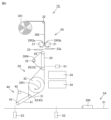
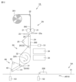
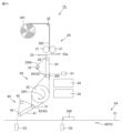
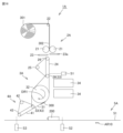
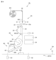
- FIG. 4 is a schematic plan view of the label pasting device according to this embodiment.
- FIG. 5 is a front view of the feeding belt and conveyor belt shown in FIG. 4.
- FIG. 6 is a diagram showing the configuration of functional blocks of the label pasting device according to this embodiment.
- FIG. 7 is a front view of the conveyor belt and label pasting belt shown in FIG. 4.
- the label pasting apparatus 1A continuously manufactures a plurality of labeled articles 100 using the above-described articles 200 and labels 300 as materials.
- the label pasting device 1A includes a feeding mechanism 2A that feeds out the label 300 to an activation mechanism 3A, and an activation mechanism that activates the adhesive layer 300b included in the label 300 while conveying the label 300. 3A, and a label sticking mechanism 4A that sticks the label 300 with the activated adhesive layer 300b on the article 200 in the activation mechanism 3A.
- These three mechanisms are arranged in the order of the feeding mechanism 2A, the activation mechanism 3A, and the label pasting mechanism 4A from the upstream side to the downstream side along the transport path of the label 300.
- the label pasting device 1A is configured so that mechanical operations are performed by dividing into these three mechanisms.
- the label pasting device 1A further includes an article conveyance mechanism 5A that continuously conveys the article 200 on a conveyance path different from the conveyance path of the label 300.
- the feeding mechanism 2A includes a pair of label supply rollers 21, a driven roller 22 that rotates as the label feeding roller 21 rotates, a cut blade 23, a label support section 23a, and a feeding belt. 24, a drive roller 25, and a pair of driven rollers 26 that rotate in accordance with the rotation of the drive roller 25.
- the label continuous body 302 is held by a pair of label supply rollers 21 that are arranged to face each other and a driven roller 22 that rotates as the label supply rollers 21 rotate.
- the pair of label supply rollers 21 wind up the continuous label body 302 by rotating them. Thereby, the continuous label body 302 is supplied to the nip formed between the pair of label supply rollers 21 . Moreover, the pair of label supply rollers 21 supply the continuous label body 302 by a predetermined length to the cut blade 23 and the label support section 23a by being driven to rotate.
- the cut blade 23 approaches the single continuous label body 302 supported from one side by the label supporting part 23a so as to sandwich the single continuous label body 302 from the opposite side of the label supporting part 23a, or the cutting blade 23 approaches the single continuous label body 302 supported from one side by the label supporting part 23a, or It is configured to be able to be driven in a direction away from the center.
- sandwiching the single label continuous body 302 between the cutting blade 23 and the label support portion 23a in this way one of the individual labels 300 included in the single label continuous body 302 is separated into pieces. cut out.
- the cut out label 300 is placed on the feeding belt 24.
- the cutting blade 23 is driven by an actuator (not shown) or the like. Power is supplied to the actuator by an internal power source (not shown) or an external power source (not shown). For connection with an external power source, for example, an AC (Alternating Current) adapter (not shown) or the like is used.
- an AC (Alternating Current) adapter for example, an AC (Alternating Current) adapter (not shown) or the like is used.
- the feeding belt 24 is held by a driving roller 25 that drives it and a pair of driven rollers 26 that rotate as the driving roller 25 rotates.
- the feeding belt 24 is driven to revolve by the driving roller 25 .
- the drive roller 25 is rotationally driven by a motor (not shown) or the like.
- the feeding belt 24 includes a first holding belt 24a and a second holding belt 24b.
- Three label holding stands 24c are arranged adjacent to the first holding belt 24a and the second holding belt 24b. More specifically, the first holding belt 24a, the second holding belt 24b, and the three label holding stands 24c are arranged such that the label holding stand 24c, the first holding belt 24a, and the label The holding stand 24c, the second holding belt 24b, and the label holding stand 24c are arranged in this order.
- the materials of the first holding belt 24a and the second holding belt 24b are not particularly limited, but the first end holding belt 31a, the second end holding belt 31b and the center It is preferable that the material is the same as that of the holding belt 31c.
- the material of the label holding stand 24c is not particularly limited, but it is preferably made of a metal material or the like that has less friction with the label 300. Thereby, it is possible to effectively prevent the label 300 being transported from being distorted.
- a rotating belt (not shown) can be used instead of the label holding stand 24c. The rotating belt rotates at the same speed as the first holding belt 24a and the second holding belt 24b.
- the label is stabilized because it is conveyed at the same conveyance speed by the rotating belt, the first holding belt 24a, and the second holding belt 24b.
- the rotating belt may be integrated with the first holding belt 24a or the second holding belt 24b to hold the label.
- the rotating belt is preferably made of the same material as the first holding belt 24a and the second holding belt 24b.
- the label 300 placed on the feeding belt 24 is suctioned and held on the feeding belt 24 by suction by a vacuum mechanism (not shown) through a plurality of suction holes provided in the first holding belt 24a and the second holding belt 24b. be done. Further, when a rotating belt is used, it is more preferable that the rotating belt also has a plurality of suction holes and is held in the same manner.
- the label 300 placed on the feeding belt 24 configured as described above is first made to wait at a predetermined position on the conveyance path of the label 300 by the feeding belt 24. Next, by driving the feeding belt 24 by the driving roller 25, the label 300 is conveyed by the feeding belt 24 and fed out to the activation mechanism 3A at a predetermined timing.
- the activation mechanism 3A includes a conveyor belt 31, a drive roller 32, two driven rollers 33 that rotate as the drive roller 32 rotates, an energy source 34, and a control section 35. It is equipped with
- the conveyor belt 31 is held by a drive roller 32 that drives it and two driven rollers 33 that rotate as the drive roller 32 rotates.
- the conveyor belt 31 configured in this manner is driven to rotate by the driving roller 32 .
- the drive roller 32 is rotationally driven by a motor (not shown) or the like.
- the conveyance belt 31 is configured such that the conveyance path of the label 300 is bent after passing through an irradiation area 31e, which will be described later. Thereby, the area required for installing the label pasting device 1A can be reduced compared to a case where the conveyance path of the label 300 by the conveyance belt 31 is configured on a straight line without bending.
- the conveyor belt 31 includes a first end holding belt 31a that holds one of the pair of ends of the label 300 in a direction perpendicular to the conveying direction of the conveyor belt 31, and a first end holding belt 31a that holds the other end. It includes a second end holding belt 31b and a center holding belt 31c that holds the center of the label 300 by being located between the first end holding belt 31a and the second end holding belt 31b.
- two label holding stands 31d are arranged adjacent to the first end holding belt 31a, the second end holding belt 31b, and the center holding belt 31c. More specifically, the first end holding belt 31a, the second end holding belt 31b, the central holding belt 31c, and the two label holding stands 31d are arranged such that the first end holding belt 31a, the second end holding belt 31b, the central holding belt 31c, and the two label holding stands 31d are arranged so that the first end The section holding belt 31a, the label holding stand 31d, the center holding belt 31c, the label holding stand 31d, and the second end holding belt 31b are arranged in this order.
- the first end holding belt 31a, the second end holding belt 31b, and the center holding belt 31c are preferably made of a crosslinked rubber composition containing a rubber component and a fluorosurfactant, and further Preferably, one or two of rubber components such as millable urethane rubber, ethylene- ⁇ -olefin elastomer, chloroprene rubber, chlorosulfonated polyethylene rubber, nitrile rubber, hydrogenated nitrile rubber, silicone rubber, fluororubber, etc. shall include one or more. With this configuration, the wear resistance of the first end holding belt 31a, the second end holding belt 31b, and the center holding belt 31c can be improved.
- the materials of the first end holding belt 31a, the second end holding belt 31b, and the center holding belt 31c are not particularly limited to these, and may be changed as appropriate depending on the environment in which the conveyor belt 31 is used. good.
- the first end holding belt 31a, the second end holding belt 31b, and the center holding belt 31c are made of chloroprene rubber.
- the material of the label holding stand 31d is not particularly limited, it is preferably a metal material or the like that has less friction with the label 300. Thereby, it is possible to effectively prevent the label 300 being transported from being distorted.
- a rotating belt (not shown) can be used instead of the label holding stand 31d. The rotating belt rotates at the same speed as the first end holding belt 31a, the second end holding belt 31b and the central holding belt 31c. The label is stabilized because it is conveyed at the same conveyance speed by the rotating belt, the first end holding belt 31a, the second end holding belt 31b, and the central holding belt 31c.
- the rotating belt may be integrated with the first end holding belt 31a, the second end holding belt 31b, or the central holding belt 31c to hold the label.
- the rotating belt is preferably made of the same material as the first end holding belt 31a, second end holding belt 31b, and center holding belt 31c.
- the label 300 placed on the conveyor belt 31 is sucked by a vacuum mechanism (not shown) through a plurality of suction holes provided in the first end holding belt 31a, the second end holding belt 31b, and the central holding belt 31c. As a result, it is attracted and held on the conveyor belt 31. Further, when a rotating belt is used, it is more preferable that the rotating belt also has a plurality of suction holes and is held in the same manner.
- the label 300 transferred from the feeding mechanism 2A to the conveyor belt 31 configured in this way is conveyed by the conveyor belt 31 and transferred to the label pasting mechanism 4A by driving the conveyor belt 31 by the drive roller 32. It will be rolled out.
- the energy source 34 irradiates energy 34a that activates the adhesive layer 300b of the label 300.
- the energy source 34 is arranged adjacent to the conveyor belt 31 so that an irradiation area 31e (see especially FIG. 5), which is an area to which the energy 34a is irradiated, is provided on the orbit of the conveyor belt 31.
- the irradiation area 31e is located between the position on the trajectory of the conveyor belt 31 where the label 300 is transferred from the feeding mechanism 2A and the position where the label 300 is transferred to the label pasting mechanism 4A. become.
- a pattern is attached to the irradiation area 31e for easy understanding (the same applies to FIG. 15, which will be described later).
- Examples of the energy 34a irradiated from the energy source 34 include optical energy such as ultraviolet rays and infrared rays, and thermal energy such as hot air. Note that the energy 34a of the energy source 34 is not particularly limited to these, and is preferably selected as appropriate depending on the activation properties of the material used as the adhesive layer 300b.
- an LED lamp, a fluorescent lamp, or the like is used as the energy source 34. If the start and stop of irradiation of the energy 34a is repeated during continuous production of a plurality of labeled articles 100, it is preferable to use an LED lamp as the energy source 34.
- the number of energy sources 34 is not particularly limited, and may be changed as appropriate depending on the energy 34a irradiation ability of the energy source 34 used, the amount of energy 34a necessary for activating the adhesive layer 300b, etc. .
- two energy sources 34 are arranged side by side along the transport path of the label 300. Thereby, even when the continuous production of labeled articles 100 is sped up, sufficient irradiation time for activation of adhesive layer 300b can be ensured.
- the energy source 34 is supplied with power by an internal power source (not shown) or an external power source (not shown). For connection with an external power source, for example, an AC adapter (not shown) or the like is used.
- the adhesive layer 300b of the label 300 conveyed by the conveyor belt 31 is activated by passing through the irradiation area 31e provided by the energy source 34 configured as described above.
- the control unit 35 controls the drive of the drive roller 32 and the like and the irradiation of the energy source 34.
- the control unit 35 also controls the drive roller 25 of the feeding mechanism 2A and the drive roller 42 of the label pasting mechanism 4A, as will be described later.
- a control section different from the control section 35 may be further provided in the label pasting device 1A.
- the control unit 35 includes, as main components, a CPU (Central Processing Unit) that executes a program, a ROM (Read Only Memory)/RAM (Random Access Memory), and a label detection sensor S1 to be described later. , and a calculation section that performs various calculations based on various information input from the first article detection sensor S2 and the second article detection sensor S3.
- the ROM/RAM includes a ROM that stores data in a non-volatile manner and a RAM that volatilely stores data generated by execution of a program by a CPU.
- Each component of the control unit 35 is connected to each other by a data bus.
- Processing in the CPU is realized by each piece of hardware and software executed by the CPU.
- Such software is stored in ROM/RAM in advance.
- Power is supplied to the control unit 35 by an internal power source (not shown) or an external power source (not shown).
- an external power source for example, an AC adapter (not shown) or the like is used.
- the label detection sensor S1 is a sensor for detecting that the label 300 placed on and conveyed by the feeding belt 24 has been conveyed to a predetermined position, and is provided on the feeding belt 24.
- the detection information of the label 300 obtained by the label detection sensor S1 is output to the control section 35 and used to drive the drive roller 25 that drives the feed belt 24.
- the first article detection sensor S2 is a sensor for detecting that an article 200 placed on and conveyed by the article conveyance belt 51, which will be described later, has been conveyed to a predetermined position.
- the first article detection sensor S2 is provided on the article conveyance belt 51.
- the detection information of the article 200 obtained by the first article detection sensor S2 is output to the control unit 35, and is used to drive the drive roller 25 that drives the feeding belt 24 and the drive roller that drives the label pasting belt 41, which will be described later. It is used to drive 42.
- the second article detection sensor S3 is a sensor for detecting that the article 200 placed on and conveyed by the article conveyance belt 51 has been conveyed to a predetermined position.
- the second article detection sensor S3 is provided on the article conveyance belt 51 so as to be located along the conveyance path of the article 200 and downstream from the first article detection sensor S2.
- the detection information of the article 200 obtained by the second article detection sensor S3 is output to the control section 35 and used to drive the drive roller 42 that drives the label pasting belt 41.
- the label pasting mechanism 4A includes a label pasting belt 41, a drive roller 42, and a driven roller 43 that rotates as the drive roller 42 rotates.
- the label pasting belt 41 is held by a drive roller 42 that drives it and a driven roller 43 that rotates as the drive roller 42 rotates.
- the label pasting belt 41 configured in this manner is driven to rotate by the driving roller 42 .
- the drive roller 42 is rotationally driven by a motor (not shown) or the like.
- the label pasting belt 41 includes a first holding belt 41a and a second holding belt 41b.
- Three label holding stands 41c are arranged adjacent to the first holding belt 41a and the second holding belt 41b. More specifically, the first holding belt 41a, the second holding belt 41b, and the three label holding stands 41c are arranged such that the label holding stand 41c, the first holding belt 41a , label holding stand 41c, second holding belt 41b, and label holding stand 41c are arranged in this order.
- the materials of the first holding belt 41a and the second holding belt 41b are the same as those of the first end holding belt 31a, the second end holding belt 31b, and the center holding belt 31c included in the conveyor belt 31 described above. It is preferable that Further, the material of the label holding stand 41c is not particularly limited, but it is preferable to use a metal material or the like that has less friction with the label 300. Thereby, it is possible to effectively prevent the label 300 being transported from being distorted. Further, a rotating belt (not shown) can be used instead of the label holding stand 41c. The rotating belt rotates at the same speed as the first holding belt 41a and the second holding belt 41b.
- the label is stabilized because it is conveyed at the same conveyance speed by the rotating belt, the first holding belt 41a, and the second holding belt 41b.
- the rotating belt may be integrated with the first holding belt 41a or the second holding belt 41b to hold the label.
- the rotating belt is preferably made of the same material as the first holding belt 41a and the second holding belt 41b.
- the label 300 placed on the label pasting belt 41 is sucked by a vacuum mechanism (not shown) through a plurality of suction holes provided in the first holding belt 41a and the second holding belt 41b. It is held by suction on top. Further, when a rotating belt is used, it is more preferable that the rotating belt also has a plurality of suction holes and is held in the same manner.
- the label 300 transferred from the activation mechanism 3A to the label pasting belt 41 configured in this way is first put on standby on the label pasting belt 41.
- the label pasting belt 41 is driven by the drive roller 42, so that the label 300 is conveyed by the label pasting belt 41.
- the article conveyance mechanism 5A includes an article conveyance belt 51, a drive roller (not shown), and a driven roller that rotates as the drive roller rotates.
- the article conveyance belt 51 is held by a drive roller that drives it and a driven roller that rotates as the drive roller rotates.
- the article conveyance belt 51 configured in this manner is driven to rotate by driving the drive roller.
- the drive roller is rotationally driven by a motor (not shown) or the like.
- the material of the article conveyance belt 51 is not particularly limited, and various materials can be used.
- the article 200 placed on the article conveying belt 51 is suctioned and held on the article conveying belt 51 by being sucked by a vacuum device (not shown) or the like from a plurality of suction holes provided in the article conveying belt 51.
- the article conveyance belt 51 is arranged so as to be closest to the label attachment belt 41 at the most downstream position on the conveyance path of the label 300 by the label attachment belt 41.
- the label 300 conveyed by the label pasting belt 41 joins the article 200 conveyed by the article conveyance belt 51.
- the label 300 is attached to the article 200 at a predetermined timing at the position.
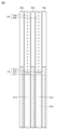
- FIG. 8 is a flowchart chronologically showing the operating state of the label pasting device according to the present embodiment.
- 9 to 14 and 16 to 20 are schematic plan views for explaining each point in the flowchart shown in FIG. 8, respectively.
- FIG. 15 is a front view of the feed belt and conveyor belt shown in FIG. 14.
- the label pasting apparatus 1A continuously manufactures a plurality of labeled articles 100 using the article 200 and the label 300 as materials.
- the original label 301 is placed near the feeding mechanism 2A. Further, a single continuous label body 302 forming the original label fabric 301 is hung on the driven roller 22 , and the leading end of the continuous label body 302 is set in the nip portion of the pair of label supply rollers 21 .
- the first main surface 300(1) which is the main surface on the side defined by the adhesive layer 300b of the pair of main surfaces of the label 300, is energized. is placed so as to face the source 34.
- the control unit 35 starts driving the drive roller 32, and the drive roller 32 rotates in the direction of arrow DR1 shown in FIG. Thereby, the conveyor belt 31 is driven to rotate at a predetermined speed. Note that the driving of the conveyor belt 31 continues until it is stopped at time T11, which will be described later.
- the control unit 35 starts driving the pair of label supply rollers 21 and the drive roller 25 in the feeding mechanism 2A.
- the pair of label supply rollers 21 rotate in the directions of arrows DR3a and DR3b shown in FIG. 9, respectively.
- the single label continuous body 302 is wound up by the label supply roller 21, and is supplied downstream from the cut blade 23 and the label support section 23a by the length of the label 300 of the label continuous body 302. be done.
- the drive roller 25 rotates in the direction of arrow DR4 shown in FIG. 9, thereby driving the feeding belt 24 to rotate.
- the leading end portion of the single continuous label body 302 is transferred from the label supply roller 21 to the feeding belt 24.
- the feeding belt 24 is controlled to accelerate from a standby state to the speed of the label feeding roller 21 when receiving the leading end portion of the continuous label body 302 from the label feeding roller 21 . Thereby, it is possible to effectively prevent distortion of the continuous label body 302 when the continuous label body 302 is transferred.
- the label 300 is cut out at time T1.
- control unit 35 drives the cutting blade 23 in the direction of arrow AR1a shown in FIG.
- the portion of the continuous label body 302 supplied to the cutting blade 23 and the label support section 23a is separated into pieces, and as a result, the label 300 is cut out.
- the label 300 is cut out while the label supply roller 21 and the feeding belt 24 are not driven.
- the cut out label 300 is placed on the feeding belt 24.
- the article conveyance mechanism 5A conveyance of a plurality of articles 200 including article 200 is started. More specifically, the plurality of articles 200 placed on the article conveyance belt 51 are continuously conveyed in the direction of arrow AR10 shown in FIG.
- the label 300 is conveyed by the feed belt 24.
- the cutting blade 23 is moved backward.
- the drive roller 25 rotates, the label 300 is conveyed on the conveyance path of the label 300 by the feeding belt 24.
- the label 300 is attracted to the feeding belt 24 by negative pressure from a blower, a vacuum device, or the like.
- the label 300 is placed on standby on the feeding belt 24.
- the label detection sensor S1 provided on the above-described feeding belt 24 detects that the label 300 has been conveyed to a predetermined position, and outputs this detection information to the control unit 35.
- the control unit 35 that has obtained this information stops driving the drive roller 25, so that the label 300 waits at a predetermined position.
- the label 300 is transferred at time T4.
- the first article detection sensor S2 provided on the article conveying belt 51 of the article conveying mechanism 5A detects that the article 200 placed on and conveyed by the article conveying belt 51 is in a predetermined state.
- the conveyance to the position is detected, and this detection information is output to the control section 35.
- the control unit 35 that has obtained this information resumes driving the drive roller 25, and thereby the label 300 is fed out from the feeding belt 24 of the feeding mechanism 2A to the conveyance belt 31 of the activation mechanism 3A and transferred. It turns out.
- the feed belt 24 is controlled to accelerate from the standby state at time T3 to the speed of the conveyor belt 31.
- the belt length of the feeding belt 24 can be shortened compared to the case where the feeding belt is configured as one piece with the conveying belt.
- the feed belt 24 can be accelerated in a shorter time.
- the continuous production of labeled articles 100 can be sped up.
- the drive rollers, motors, etc. used for accelerating the feeding belt 24 can be made smaller, so the device can be made more compact.
- by accelerating the feeding belt 24 to the speed of the conveyor belt 31 and then feeding out the label 300 it is possible to effectively prevent the label 300 from being distorted when the label 300 is transferred. can.
- the energy source 34 starts irradiating the energy 34a, and the adhesive layer 300b of the label 300 is activated.
- the label 300 transferred to the conveyor belt 31 that has been continuously driven is a label caused by the conveyor belt 31. It is transported on 300 transport routes. At this time, the label 300 is attracted to the conveyor belt 31 by negative pressure from a blower, a vacuum device, or the like.
- the control unit 35 starts irradiation of the energy 34a by the energy source 34.
- an irradiation area 31e is provided on the trajectory of the conveyor belt 31, which is an area to which the energy 34a is irradiated. Note that the irradiation of the energy 34a by the energy source 34 continues until it is stopped at time T6, which will be described later.
- the label 300 passes through an irradiation area 31e provided on the trajectory of the conveyor belt 31.
- the adhesive layer 300b of the label 300 is irradiated with the energy 34a.
- the adhesive layer 300b becomes activated.
- the conveyor belt 31 includes the first end holding belt 31a, the second end holding belt 31b, and the center holding belt 31c (see especially FIGS. 5 and 15). With this configuration, it is possible to effectively prevent the label 300 from warping when passing through the irradiation area 31e, but the details will be described later.
- control unit 35 stops the energy source 34 from irradiating the energy 34a.
- the label 300 is transferred at time T7.
- control unit 35 starts driving the drive roller 42, and the drive roller 42 rotates in the direction of arrow DR5 shown in FIG. Thereby, the label pasting belt 41 is driven to rotate.
- the label 300 with the adhesive layer 300b activated in the irradiation area 31e is further transported toward the downstream side on the transport path of the label 300 by the transport belt 31.
- the label pasting belt 41 of the label pasting mechanism 4A receives the label 300 from the conveyor belt 31 of the activation mechanism 3A.
- the label pasting belt 41 when the label pasting belt 41 receives the label 300 from the conveyor belt 31, it is controlled to accelerate from the standby state at time T7 to the speed of the conveyor belt 31. In this way, when the label pasting belt 41 is provided separately from the conveyor belt 31, the belt length of the label pasting belt 41 is shorter than when the label pasting belt is configured as one body with the conveyor belt. Since the length can be shortened, the label pasting belt 41 can be accelerated in a shorter time. Thereby, the continuous production of labeled articles 100 can be sped up. Furthermore, compared to the case where the label pasting belt is integrated with the conveyor belt, the drive rollers, motors, etc. used to accelerate the label pasting belt 41 can be made smaller, so the device can be made more compact. . Furthermore, by accelerating the label pasting belt 41 to the speed of the conveyor belt 31 and then receiving the label 300, distortion of the label 300 during transfer of the label 300 can be effectively prevented. be able to.
- the label 300 is placed on standby on the label pasting belt 41.
- the control unit 35 stops driving the drive roller 42.
- the label 300 is placed on standby at a predetermined position on the label pasting belt 41.
- the label 300 is attached to the article 200.
- the second article detection sensor S3 provided on the article conveyance belt 51 of the article conveyance mechanism 5A detects that the article 200 has been conveyed to a predetermined position, and transmits this detection information to the control unit. Output to 35.
- the article 200 is placed on the article conveyance belt 51 and conveyed.
- the control unit 35 which has obtained the information that the second article detection sensor S3 has detected the article 200, resumes driving the drive roller 42.
- the label attaching belt 41 is controlled to accelerate from the standby state at time T8 to the conveying speed of the article conveying belt 51. Thereby, it is possible to effectively prevent distortion of the label 300 when the label 300 is attached.
- the manufactured labeled article 100 is transported downstream.
- the operations at times T0 to T11 will be repeated.
- the setting of the original label 301 and the driving of the conveyor belt 31 at time T0 are performed only when manufacturing the first labeled article 100, and the operation at time T11 (i.e., the driving of the conveyor belt 31 is stopped). ) may be performed only when the production of the last labeled article 100 is completed.
- label pasting In the case where labeled articles 100 are continuously manufactured by continuously pasting a plurality of labels 300 onto a plurality of articles 200, cutting out the first label 300 (i.e., label pasting)
- the conveyor belt 31 is driven at a predetermined speed from the start of operation of the apparatus 1A to the time when the last labeled article 100 is carried out (that is, the end of operation of the label pasting apparatus 1A).
- the label pasting device 1A according to the present embodiment which is equipped with an activation mechanism that activates the adhesive layer of the label, the durability of the device is improved. There is.
- the heat generated on the belt by these energies and the irradiated light energy itself may cause damage.
- the belt will deteriorate.
- the portion that is continuously irradiated with the energy 34a is heated to a very high temperature. In this case, the belt deteriorates particularly severely.
- the control unit 35 starts from a time before the label 300 is transferred onto the conveyor belt 31 at the time T4.
- the driving of the conveyor belt 31 via the drive roller 32 is started, and this driving of the conveyor belt 31 is continued until the label 300 is transferred to the label pasting belt 41 at time T7.
- the control unit 35 when the label 300 passes through the irradiation area 31e, the control unit 35 causes the energy source 34 to irradiate the energy 34a to the irradiation area 31e.
- the control unit 35 also controls the conveyor belt 31 to move at a predetermined speed via the drive roller 32 after the label 300 is transferred to the feeding mechanism 2A until the label 300 is transferred to the label pasting mechanism 4A. Drive it with.
- the conveyor belt 31 since the conveyor belt 31 is driven to rotate while the energy 34a is irradiated, the heat and light energy itself generated by the irradiation of the energy 34a is absorbed into the conveyor belt 31. It is suppressed from occurring only in a specific part of the body. This prevents a specific portion of the conveyor belt 31 from becoming high temperature and prevents a specific portion of the conveyor belt 31 from being continuously irradiated with light energy, and effectively prevents deterioration of the conveyor belt 31 due to the heat and light energy. Can be suppressed.
- the conveyor belt 31 continues to be driven even when the energy source 34 is not irradiating the energy 34a.
- the energy source 34 is not irradiating the energy 34a.
- the label pasting device 1A is configured so that the mechanical operation is performed by dividing into three mechanisms: the feeding mechanism 2A, the activation mechanism 3A, and the label pasting mechanism 4A. ing. Thereby, it becomes possible to operate the label pasting mechanism 4A continuously while operating the feeding mechanism 2A and the activation mechanism 3A intermittently. Further, by dividing the mechanism into the three mechanisms described above, it is also possible to independently set the transport speed of the label 300 in each mechanism.
- the conveyor belt 31 is driven so that the conveyance speed of the conveyor belt 31 is optimal for activating the adhesive layer 300b. can be controlled. This makes it possible to ensure the activation of the adhesive layer 300b, thereby improving the accuracy of attaching the label 300 to the article 200.
- the driving of the label sticking belt 41 when the label 300 is stuck to the article 200 is performed so that the conveying speed of the label sticking belt 41 is equal to the conveying speed of the article conveying belt 51. It can be controlled to be the same. This makes it possible to attach the label 300 to the article 200 without causing wrinkles, folds, etc. in the label 300.
- the conveyor belt 31 that holds the label 300 in the irradiation area 31e where the adhesive layer 300b is activated is includes a first end holding belt 31a, a second end holding belt 31b, and a center holding belt 31c.
- both ends of the label 300 in the direction perpendicular to the conveying direction of the conveyor belt 31 are held by the first end holding belt 31a and the second end holding belt 31b.
- the adhesive layer 300b By activating the adhesive layer 300b, it is possible to effectively prevent the label 300 from warping. Thereby, the accuracy of attaching the label 300 to the article 200 by the label attaching device 1A can be improved.
- the above-mentioned effects can be significantly obtained because the label 300 is attracted to the conveyor belt 31 by a vacuum device or the like.
- irradiation of the energy 34a by the energy source 34 is started at time T5 shown in FIG. 8, and the irradiation is stopped at time T6.
- the irradiation of the energy 34a by the energy source 34 may be controlled to be performed intermittently only while the label 300 is being transported by the transport belt 31 of the activation mechanism 3A.
- the label pasting device 1A in the label pasting device 1A according to the present embodiment described above, various processes are performed on the label 300 by three mechanisms: the feeding mechanism 2A, the activation mechanism 3A, and the label pasting mechanism 4A.
- the label pasting device 1A does not necessarily have to include the feeding mechanism 2A and the label pasting mechanism 4A having the above-described configurations, and feeding the label 300 to the activation mechanism 3A and pasting the label 300 onto the article 200 is not necessarily necessary. , for example, may be done manually.
- an auxiliary belt driven to revolve may be provided at a position corresponding to the label holding stands. It is preferable that the auxiliary belt is made of the same material as the feed-out belt 24, etc. adjacent thereto, and is driven to revolve at the same speed.
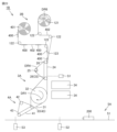
- FIG. 21 is a schematic plan view of a label pasting device according to the second embodiment.
- FIG. 22 is a flowchart chronologically showing the operating state of the label pasting apparatus according to the second embodiment
- FIG. 23 is a schematic plan view for explaining each point in the flowchart shown in FIG. 22.
- the label pasting device 1B according to this embodiment will be described below with reference to FIGS. 21 to 23.
- the label pasting device 1B according to this embodiment is different from the label pasting device 1A according to the first embodiment described above in the configuration of the label and the feeding mechanism.
- the label 400 in the label pasting device 1B is formed by peeling a plurality of labels 400 from a single support sheet 402 on which a plurality of labels 400 are supported.
- This is a so-called tack label.
- a single support sheet 402 to which a plurality of labels 400 are attached forms a label material 401 by being rolled up into a roll.
- a release film having a base film and a release layer provided on one of the pair of main surfaces of the base film is used.
- the material of the base film constituting the support sheet 402 is not particularly limited, and for example, a synthetic resin film such as polyester resin, polystyrene resin, vinyl chloride resin, etc., or a plurality of laminated resin layers of different or the same type. Examples include laminated resin films, papers such as synthetic paper, plain paper, and high-quality paper, and laminated films in which two or more films selected from these are laminated.
- the thickness of the base film is not particularly limited, but is preferably, for example, 15 ⁇ m or more and 300 ⁇ m or less.
- the release layer constituting the support sheet 402 is formed by applying a release agent containing, for example, a silicone resin to the surface of the base film.
- the thickness of the release layer is not particularly limited, but is preferably, for example, 0.1 ⁇ m or more and 3 ⁇ m or less.
- the plurality of labels 400 are supported so as to be positioned at regular intervals in the longitudinal direction of the support sheet 402 on the side defined by the release layer of the pair of main surfaces of the support sheet 402.
- the label 400 is composed of a base material, an adhesive layer, and a design printing layer.
- the configurations such as the materials of the base material, adhesive layer, and design printing layer of the label 400 are the same as those of the base material 300a, adhesive layer 300b, and design printing layer 300c of the label 300, so the description thereof will not be repeated.
- the feeding mechanism 2B of the label pasting device 1B includes a collection roller 121, four driven rollers 122 that rotate in accordance with the rotation of the collection roller 121, and a peeling section 123.
- the collection roller 121 When the collection roller 121 is rotationally driven, it winds up the support sheet 402 forming the original label fabric 401 from the original label fabric 401 placed near the feeding mechanism 2B. As a result, the support sheet 402 from which the label 400 has been peeled off is accumulated on the collection roller 121.
- the collection roller 121 is rotationally driven by a motor or the like (not shown).
- the peeling unit 123 is for peeling off the label 400 from the single support sheet 402 supplied from the original label 401 and to which the label 400 is attached.
- the peeling section 123 is constituted by a wedge-shaped plate member in plan view, the tip of which is formed at a sharp angle.
- the collection roller 121 rotates in the direction of arrow DR6 shown in FIG.
- the support sheet 402 to which the label 400 is attached is conveyed along the conveyance path provided by the collection roller 121 and the four driven rollers 122.
- the support sheet 402 to which the label 400 is attached is sharply bent at the tip of the peeling part 123 along the shape of the peeling part 123.
- the label 400 is peeled off from the support sheet 402, and at the next time point T4, the peeled label 400 is transferred from the feeding mechanism 2B to the conveyor belt 31 of the activation mechanism 3A. Become.
- FIG. 24 is a schematic plan view of the label pasting device according to the third embodiment in the first state
- FIG. 25 is a schematic plan view of the label pasting device according to the third embodiment in the second state.
- the label pasting device 1C according to this embodiment will be described below with reference to FIGS. 24 and 25.
- the label pasting device 1C according to the present embodiment is different in the configuration of the feeding mechanism when compared with the label pasting devices 1A and 1B according to the first and second embodiments described above. Thereby, the label pasting device 1C is configured to be able to be used both for manufacturing labeled articles using the label 300 made of a linerless label and for manufacturing labeled articles using the label 400 made of a tack label. has been done.
- the feeding mechanism 2C constituting the label pasting device 1C includes a pair of label supply rollers 21 and a driven roller 22, each of which has a non-adhesive treatment applied to their surfaces.
- the feeding mechanism 2C has a part thereof having substantially the same configuration as the feeding mechanism 2A in Embodiment 1 (hereinafter, this state will be referred to as the first state of the label pasting device 1C). Note that in the first state, the peeling section 123 is on standby at a predetermined position outside the label pasting device 1C.
- the labeled article 100 using the label 300 can be manufactured. It becomes possible to do it.
- the label pasting device 1C in the label pasting device 1C in the first state, one of the pair of label supply rollers 21 and the label support section 23a are connected.
- the peeling part 123 which was waiting at a predetermined position outside the label pasting device 1C, is moved in the direction of arrow AR30 shown in FIG. , is attached at a position facing the other of the pair of label supply rollers 21 and the cutting blade 23.
- the original label 301 is replaced with the original label 401.
- the feeding mechanism 2C has a part that is almost the same configuration as the feeding mechanism 2B in the second embodiment (hereinafter, this state will be referred to as the label pasting device 1C). (referred to as the second state).
- the labeled article 100 using the label 400 can be manufactured. It becomes possible to do it.
- the present invention can be used both for producing labeled articles using linerless labels and for producing labeled articles using tack labels.
Abstract
The present invention addresses the problem of improving the durability of a label affixing device provided with an activation mechanism that activates an adhesive layer of a label. A label affixing device 1A comprises: an activation mechanism 3A including a conveyor belt 31 and an energy source 34; a feed mechanism 2A; and a label affixing mechanism 4A. An irradiation region 31e irradiated by energy 34a from the energy source 34, the energy 34a activating an adhesive layer of a label 300, is located on a track of the conveyor belt 31 between a position at which the label 300 is transferred from the feed mechanism 2A and a position at which the label 300 is transferred to the label affixing mechanism 4A. The energy source 34 emits the energy 34a when the label 300 passes through the irradiation region 31e, and the conveyor belt 31 is driven at a prescribed speed from when the label 300 is transferred to the feed mechanism 2A until the label 300 is transferred to the label affixing mechanism 4A.
Description
本発明は、搬送される物品に対してラベルを貼り付けるラベル貼り付け装置に関する。
TECHNICAL FIELD The present invention relates to a label affixing device for affixing labels to transported articles.
たとえば、欧州特許出願公開第3404644号明細書(特許文献1)には、ラベルに含まれる接着剤層を活性化させる活性化機構と、活性化機構にラベルを繰り出す繰り出し機構と、活性化機構において接着剤層が活性化されたラベルを物品に貼り付けるラベル貼り付け機構とを備えるラベル貼り付け装置が開示されている。
For example, European Patent Application Publication No. 3404644 (Patent Document 1) describes an activation mechanism that activates an adhesive layer included in a label, a feeding mechanism that feeds out a label to the activation mechanism, and an activation mechanism that feeds out a label to the activation mechanism. A labeling apparatus is disclosed that includes a labeling mechanism for applying a label with an activated adhesive layer to an article.
しかしながら、上記特許文献1に開示のラベル貼り付け装置にあっては、ラベルに含まれる接着剤層を活性化させるために活性化機構にて照射されるエネルギーによって発生する熱や照射される光エネルギーそのものにより、当該活性化機構においてラベルを搬送するベルトが劣化してしまう問題が発生し得る。
However, in the label pasting device disclosed in Patent Document 1, heat generated by energy irradiated by the activation mechanism and light energy irradiated to activate the adhesive layer included in the label are This may cause a problem in that the belt that conveys the label in the activation mechanism deteriorates.
したがって、本発明は、上述した問題を解決すべくなされたものであり、ラベルの接着剤層を活性化させる活性化機構を備えるラベル貼り付け装置において、装置の耐久性の向上を図ることを目的とする。
Therefore, the present invention has been made to solve the above-mentioned problems, and an object of the present invention is to improve the durability of a label pasting device equipped with an activation mechanism for activating the adhesive layer of a label. shall be.
本発明に基づくラベル貼り付け装置は、ラベルを搬送しつつラベルに含まれる接着剤層を活性化させる活性化機構と、上記活性化機構にラベルを繰り出す繰り出し機構と、上記活性化機構において接着剤層が活性化されたラベルを物品に貼り付けるラベル貼り付け機構とを備えている。上記活性化機構は、周回するように駆動される搬送ベルトと、ラベルの接着剤層を活性化させるエネルギーを照射するエネルギー源とを備えている。上記搬送ベルトの軌道上には、上記エネルギー源によってエネルギーが照射される領域である照射領域が設けられており、上記照射領域は、上記搬送ベルトの軌道上における、上記繰り出し機構からラベルが移載される位置と、上記ラベル貼り付け機構へラベルが移載される位置との間に位置している。上記本発明に基づくラベル貼り付け装置にあっては、上記エネルギー源は、少なくともラベルが上記照射領域を通過する際に当該ラベルに向けてエネルギーを照射し、上記搬送ベルトは、上記繰り出し機構へラベルが移載されてから、当該ラベルが上記ラベル貼り付け機構へ移載されるまでの間、所定速度で駆動される。
The label pasting device according to the present invention includes an activation mechanism that activates an adhesive layer included in the label while conveying the label, a feeding mechanism that feeds out the label to the activation mechanism, and an adhesive layer in the activation mechanism. and a label application mechanism for applying the layer-activated label to the article. The activation mechanism includes a conveyor belt that is driven to rotate and an energy source that irradiates energy that activates the adhesive layer of the label. An irradiation area is provided on the orbit of the conveyor belt, which is an area to which energy is irradiated by the energy source, and the irradiation area is the area where the label is transferred from the feeding mechanism on the orbit of the conveyor belt. It is located between the position where the label is placed and the position where the label is transferred to the label pasting mechanism. In the label pasting device according to the present invention, the energy source irradiates energy toward at least the label when the label passes through the irradiation area, and the conveyor belt sends the label to the feeding mechanism. The label is driven at a predetermined speed from when the label is transferred to when the label is transferred to the label pasting mechanism.
上記本発明に基づくラベル貼り付け装置にあっては、上記繰り出し機構は、周回するように駆動される繰り出しベルトを備えており、上記繰り出し機構は、ラベル連続体を個片化し、個片化したラベルを上記繰り出しベルト上において待機させた後に上記搬送ベルトに繰り出してもよい。その場合には、上記繰り出しベルトは、ラベルを上記搬送ベルトに繰り出すに際し、待機した状態から上記搬送ベルトの速度にまで加速されることが好ましい。
In the label pasting device according to the present invention, the feeding mechanism includes a feeding belt that is driven to circulate, and the feeding mechanism separates the continuous label body into individual pieces. The label may be placed on standby on the feed belt and then fed onto the conveyor belt. In that case, the feed belt is preferably accelerated from a standby state to the speed of the conveyor belt when feeding the label onto the conveyor belt.
上記本発明に基づくラベル貼り付け装置にあっては、上記ラベル貼り付け機構は、周回するように駆動されるラベル貼り付けベルトを備えており、上記ラベル貼り付け機構は、活性化後のラベルを上記搬送ベルトから受け取り、受け取ったラベルを上記ラベル貼り付けベルト上において待機させた後に外部の搬送経路上を搬送される物品に対して供給することで貼り付けてもよい。その場合には、上記ラベル貼り付けベルトは、ラベルを上記搬送ベルトから受け取るに際し、待機した状態から上記搬送ベルトの速度にまで加速されるとともに、ラベルを物品に貼り付けるに際し、待機した状態から物品の搬送速度にまで加速されることが好ましい。
In the labeling device according to the present invention, the labeling mechanism includes a labeling belt that is driven to rotate, and the labeling mechanism attaches the activated label. The label may be received from the conveyance belt, the received label may be placed on standby on the label attachment belt, and then supplied to the article conveyed on an external conveyance path to be attached. In that case, the label application belt is accelerated from a standby state to the speed of the transport belt when receiving the label from the transport belt, and when applying the label to the article, it is accelerated from the standby state to the speed of the transport belt. It is preferable that the transport speed be accelerated to a transport speed of .
上記本発明に基づくラベル貼り付け装置にあっては、上記搬送ベルトは、当該搬送ベルトの搬送方向と直交する方向におけるラベルの一対の端部のうちの一方を保持する第1端部保持ベルトおよび他方を保持する第2端部保持ベルトと、上記第1端部保持ベルトおよび上記第2端部保持ベルトの間に位置することでラベルの中央部を保持する中央保持ベルトとを含んでいてもよい。
In the label pasting device according to the present invention, the conveyor belt includes a first end holding belt that holds one of a pair of end portions of the label in a direction perpendicular to the conveyance direction of the conveyor belt; The label may include a second end holding belt that holds the other end, and a center holding belt that holds the center of the label by being located between the first end holding belt and the second end holding belt. good.
本発明によれば、ラベルの接着剤層を活性化させる活性化機構を備えるラベル貼り付け装置において、装置の耐久性の向上を図ることができる。
According to the present invention, in a label pasting device equipped with an activation mechanism that activates the adhesive layer of a label, it is possible to improve the durability of the device.
以下、本発明の実施の形態について、図を参照して詳細に説明する。なお、以下に示す実施の形態においては、同一のまたは共通する部分について図中同一の符号を付し、その説明は繰り返さない。
Hereinafter, embodiments of the present invention will be described in detail with reference to the drawings. In the embodiments described below, the same or common parts are denoted by the same reference numerals in the drawings, and the description thereof will not be repeated.
(実施の形態1)
図1は、実施の形態1に係るラベル貼り付け装置によって製造されたラベル付き物品の正面図である。図2は、実施の形態1に係るラベル原反、ラベル連続体およびラベルの斜視図である。図3は、図2中に示すIII-III線に沿ったラベル連続体およびラベルの断面図である。まず、これら図1ないし図3を参照して、本実施の形態に係るラベル貼り付け装置によって製造されたラベル付き物品100について説明する。 (Embodiment 1)
FIG. 1 is a front view of a labeled article manufactured by the labeling apparatus according to the first embodiment. FIG. 2 is a perspective view of a label original fabric, a label continuous body, and a label according to the first embodiment. FIG. 3 is a cross-sectional view of the label continuum and the label along line III-III shown in FIG. 2. First, with reference to FIGS. 1 to 3, a labeledarticle 100 manufactured by the label pasting apparatus according to the present embodiment will be described.
図1は、実施の形態1に係るラベル貼り付け装置によって製造されたラベル付き物品の正面図である。図2は、実施の形態1に係るラベル原反、ラベル連続体およびラベルの斜視図である。図3は、図2中に示すIII-III線に沿ったラベル連続体およびラベルの断面図である。まず、これら図1ないし図3を参照して、本実施の形態に係るラベル貼り付け装置によって製造されたラベル付き物品100について説明する。 (Embodiment 1)
FIG. 1 is a front view of a labeled article manufactured by the labeling apparatus according to the first embodiment. FIG. 2 is a perspective view of a label original fabric, a label continuous body, and a label according to the first embodiment. FIG. 3 is a cross-sectional view of the label continuum and the label along line III-III shown in FIG. 2. First, with reference to FIGS. 1 to 3, a labeled
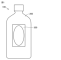
図1に示すように、ラベル付き物品100は、物品200と、物品200の胴部に貼り付けられたラベル300とを備えている。
As shown in FIG. 1, the labeled article 100 includes an article 200 and a label 300 affixed to the body of the article 200.
物品200は、たとえば飲料等を収容可能な容器や、包装容器等である。物品200の形状および材質は、特に制限されるものではない。本実施の形態においては、物品200として、軸方向の一端が閉塞され、他端が開放可能に閉塞された中空略円柱状の容器であるペットボトルが用いられている。
The article 200 is, for example, a container that can contain a drink or the like, a packaging container, or the like. The shape and material of article 200 are not particularly limited. In this embodiment, the article 200 is a PET bottle, which is a hollow, substantially cylindrical container with one end in the axial direction closed and the other end releasably closed.
図1ないし図3に示すように、ラベル300は、物品200の胴部に貼り付けられるシート状のものである。ラベル300は、当該ラベル300となる部分を複数含む単一のラベル連続体302から切り出されることによって形成されている。ラベル連続体302は、これがロール状に巻き重ねられることにより、ラベル原反301を形成している。
As shown in FIGS. 1 to 3, the label 300 is in the form of a sheet that is attached to the body of the article 200. The label 300 is formed by cutting out a single label continuous body 302 that includes a plurality of parts that will become the label 300. The continuous label body 302 forms the original label fabric 301 by winding it into a roll.
ここで、ラベル300は、剥離紙(ライナー)を具備しない、いわゆるライナーレスラベルである。そのため、ラベル300が物品200に貼り付けられるにあたって剥離紙が廃棄物として生じることはない。これにより、ラベル付き物品100が製造される際の環境負荷を低減することができる。
Here, the label 300 is a so-called linerless label that does not include a release paper (liner). Therefore, no release paper is produced as waste when the label 300 is attached to the article 200. Thereby, the environmental load when the labeled article 100 is manufactured can be reduced.
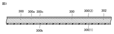
図3に示すように、ラベル300は、基材300aと、当該基材300aの一対の主面のうちの一方に設けられた接着剤層300bと、その他方に設けられたデザイン印刷層300cとを有している。これにより、ラベル300の一対の主面のうちの一方である第1主面300(1)は、接着剤層300bによって規定され、他方である第2主面300(2)は、デザイン印刷層300cによって規定されている。
As shown in FIG. 3, the label 300 includes a base material 300a, an adhesive layer 300b provided on one of a pair of main surfaces of the base material 300a, and a design printing layer 300c provided on the other. have. As a result, one of the pair of main surfaces of the label 300, the first main surface 300(1), is defined by the adhesive layer 300b, and the other, the second main surface 300(2), is defined by the design printing layer. 300c.
基材300aは、たとえばポリエチレンテレフタレートやポリプロピレン等の合成樹脂、あるいはセロファン、パルプ等の紙製の材料によって構成されてよい。基材300aの厚みは、特に制限されるものではないが、たとえば30μm以上100μm以下とすることが好ましい。
The base material 300a may be made of, for example, a synthetic resin such as polyethylene terephthalate or polypropylene, or a paper material such as cellophane or pulp. The thickness of the base material 300a is not particularly limited, but is preferably, for example, 30 μm or more and 100 μm or less.
接着剤層300bは、紫外線や赤外線等の光エネルギーによって活性化する材料や、熱風等の熱エネルギーによって活性化する材料によって構成されることが好ましい。接着剤層300bを構成する材料の主成分は、特に制限されるものではないが、オレフィンゴム、スチレン系樹脂、粘着付与剤等によって構成されることが好ましく、これらの主成分に、さらに可塑剤、オレフィンワックス、アミド系樹脂、セルロース系樹脂等が添加されてもよい。なお、接着剤層300bは、感熱粘着剤等の粘着性を有する材料で構成されてもよい。
The adhesive layer 300b is preferably made of a material that is activated by light energy such as ultraviolet rays or infrared rays, or a material that is activated by thermal energy such as hot air. The main components of the material constituting the adhesive layer 300b are not particularly limited, but are preferably composed of olefin rubber, styrene resin, tackifier, etc. In addition to these main components, a plasticizer is also added. , olefin wax, amide resin, cellulose resin, etc. may be added. Note that the adhesive layer 300b may be made of an adhesive material such as a heat-sensitive adhesive.
接着剤層300bの厚みは、特に制限されるものではないが、たとえば20μm程度とすることが好ましい。本実施の形態においては、接着剤層300bとして光エネルギーによって活性化する材料が用いられており、具体的には、紫外線活性化樹脂を含む材料が用いられている。
The thickness of the adhesive layer 300b is not particularly limited, but is preferably about 20 μm, for example. In this embodiment, a material activated by light energy is used as the adhesive layer 300b, and specifically, a material containing an ultraviolet activated resin is used.
デザイン印刷層300cには、文字や絵柄等のデザインが印刷インキ等によって表されている。デザイン印刷層300cの厚みは、特に制限されるものではないが、たとえば0.5μm以上10μm以下とすることが好ましく、さらに好適には、1.5μm以上5μm以下とされる。
On the design printing layer 300c, designs such as letters and pictures are expressed using printing ink or the like. The thickness of the design printing layer 300c is not particularly limited, but is preferably, for example, 0.5 μm or more and 10 μm or less, more preferably 1.5 μm or more and 5 μm or less.
このように構成されたラベル300は、接着剤層300bが物品200の胴部の外側表面に接着されることにより、物品200に貼り付けられている。これにより、ラベル300のデザイン印刷層300cがラベル付き物品100の外側表面に位置している。
The label 300 configured in this manner is attached to the article 200 by adhering the adhesive layer 300b to the outer surface of the body of the article 200. Thereby, the design printing layer 300c of the label 300 is located on the outer surface of the labeled article 100.
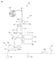
図4は、本実施の形態に係るラベル貼り付け装置の模式平面図である。図5は、図4に示す繰り出しベルトおよび搬送ベルトの正面図である。図6は、本実施の形態に係るラベル貼り付け装置の機能ブロックの構成を示す図である。図7は、図4に示す搬送ベルトおよびラベル貼り付けベルトの正面図である。次に、これら図4ないし図7を参照して、本実施の形態に係るラベル貼り付け装置1Aについて説明する。
FIG. 4 is a schematic plan view of the label pasting device according to this embodiment. FIG. 5 is a front view of the feeding belt and conveyor belt shown in FIG. 4. FIG. 6 is a diagram showing the configuration of functional blocks of the label pasting device according to this embodiment. FIG. 7 is a front view of the conveyor belt and label pasting belt shown in FIG. 4. Next, with reference to these FIGS. 4 to 7, the label pasting device 1A according to the present embodiment will be described.
本実施の形態に係るラベル貼り付け装置1Aは、要約すれば、上述した物品200およびラベル300を材料として、複数のラベル付き物品100を連続的に製造するものである。
In summary, the label pasting apparatus 1A according to the present embodiment continuously manufactures a plurality of labeled articles 100 using the above-described articles 200 and labels 300 as materials.
図4に示すように、ラベル貼り付け装置1Aは、活性化機構3Aにラベル300を繰り出す繰り出し機構2Aと、ラベル300を搬送しつつラベル300に含まれる接着剤層300bを活性化させる活性化機構3Aと、活性化機構3Aにおいて接着剤層300bが活性化されたラベル300を物品200に貼り付けるラベル貼り付け機構4Aとを備えている。これら3つの機構は、ラベル300の搬送経路に沿うように、上流側から下流側に向けて繰り出し機構2A、活性化機構3A、ラベル貼り付け機構4Aの順で位置するように配置されている。ラベル貼り付け装置1Aは、これら3つの機構に分けて機械動作が行なわれるように構成されている。
As shown in FIG. 4, the label pasting device 1A includes a feeding mechanism 2A that feeds out the label 300 to an activation mechanism 3A, and an activation mechanism that activates the adhesive layer 300b included in the label 300 while conveying the label 300. 3A, and a label sticking mechanism 4A that sticks the label 300 with the activated adhesive layer 300b on the article 200 in the activation mechanism 3A. These three mechanisms are arranged in the order of the feeding mechanism 2A, the activation mechanism 3A, and the label pasting mechanism 4A from the upstream side to the downstream side along the transport path of the label 300. The label pasting device 1A is configured so that mechanical operations are performed by dividing into these three mechanisms.
ラベル貼り付け装置1Aは、さらに、ラベル300の搬送経路とは異なる搬送経路上において物品200を連続的に搬送する物品搬送機構5Aを備えている。
The label pasting device 1A further includes an article conveyance mechanism 5A that continuously conveys the article 200 on a conveyance path different from the conveyance path of the label 300.
以下においては、まず、ラベル貼り付け装置1Aの繰り出し機構2A、活性化機構3A、ラベル貼り付け機構4Aの構成について説明する。
In the following, first, the configurations of the feeding mechanism 2A, the activation mechanism 3A, and the label pasting mechanism 4A of the label pasting device 1A will be explained.
図4に示すように、繰り出し機構2Aは、一対のラベル供給ローラー21と、当該ラベル供給ローラー21の回転に伴って従動回転する従動ローラー22と、カット刃23およびラベル支持部23aと、繰り出しベルト24と、駆動ローラー25と、当該駆動ローラー25の回転に伴って従動回転する一対の従動ローラー26とを備えている。
As shown in FIG. 4, the feeding mechanism 2A includes a pair of label supply rollers 21, a driven roller 22 that rotates as the label feeding roller 21 rotates, a cut blade 23, a label support section 23a, and a feeding belt. 24, a drive roller 25, and a pair of driven rollers 26 that rotate in accordance with the rotation of the drive roller 25.
ラベル連続体302は、互いに対向するように配置された一対のラベル供給ローラー21および当該ラベル供給ローラー21の回転に伴って従動回転する従動ローラー22によって保持されている。
The label continuous body 302 is held by a pair of label supply rollers 21 that are arranged to face each other and a driven roller 22 that rotates as the label supply rollers 21 rotate.
一対のラベル供給ローラー21は、これらが回転駆動することにより、ラベル連続体302を巻き取る。これにより、ラベル連続体302が、当該一対のラベル供給ローラー21の間に形成されたニップ部に供給される。また、一対のラベル供給ローラー21は、これらが回転駆動することにより、ラベル連続体302を所定の長さ分だけカット刃23およびラベル支持部23aに供給する。
The pair of label supply rollers 21 wind up the continuous label body 302 by rotating them. Thereby, the continuous label body 302 is supplied to the nip formed between the pair of label supply rollers 21 . Moreover, the pair of label supply rollers 21 supply the continuous label body 302 by a predetermined length to the cut blade 23 and the label support section 23a by being driven to rotate.
カット刃23は、ラベル支持部23aによって片側から支持された単一のラベル連続体302を当該ラベル支持部23aの反対側から挟み込むように当該ラベル連続体302に接近し、あるいは当該ラベル連続体302から離間する方向に駆動可能に構成されている。このように単一のラベル連続体302がカット刃23およびラベル支持部23aによって挟み込まれることにより、当該単一のラベル連続体302からこれに含まれる個々のラベル300のうちの1つが個片化されて切り出される。切り出されたラベル300は、繰り出しベルト24に載置される。
The cut blade 23 approaches the single continuous label body 302 supported from one side by the label supporting part 23a so as to sandwich the single continuous label body 302 from the opposite side of the label supporting part 23a, or the cutting blade 23 approaches the single continuous label body 302 supported from one side by the label supporting part 23a, or It is configured to be able to be driven in a direction away from the center. By sandwiching the single label continuous body 302 between the cutting blade 23 and the label support portion 23a in this way, one of the individual labels 300 included in the single label continuous body 302 is separated into pieces. cut out. The cut out label 300 is placed on the feeding belt 24.
なお、カット刃23の駆動は、図示しないアクチュエータ等によって行なわれる。当該アクチュエータには、図示しない内部電源または図示しない外部電源によって電力が供給される。外部電源との接続には、たとえば図示しないAC(Alternating Current)アダプタ等が用いられる。
Note that the cutting blade 23 is driven by an actuator (not shown) or the like. Power is supplied to the actuator by an internal power source (not shown) or an external power source (not shown). For connection with an external power source, for example, an AC (Alternating Current) adapter (not shown) or the like is used.
繰り出しベルト24は、これを駆動する駆動ローラー25および当該駆動ローラー25の回転に伴って従動回転する一対の従動ローラー26によって保持されている。繰り出しベルト24は、駆動ローラー25が駆動することにより、周回するように駆動される。駆動ローラー25は、図示しないモーター等によって回転駆動する。
The feeding belt 24 is held by a driving roller 25 that drives it and a pair of driven rollers 26 that rotate as the driving roller 25 rotates. The feeding belt 24 is driven to revolve by the driving roller 25 . The drive roller 25 is rotationally driven by a motor (not shown) or the like.
図5に示すように、繰り出しベルト24は、第1保持ベルト24aおよび第2保持ベルト24bを含んでいる。これら第1保持ベルト24aおよび第2保持ベルト24bに隣接するように、3つのラベル保持台24cが配置されている。より具体的には、第1保持ベルト24a、第2保持ベルト24bおよび3つのラベル保持台24cは、繰り出しベルト24の搬送方向と直交する方向において、ラベル保持台24c、第1保持ベルト24a、ラベル保持台24c、第2保持ベルト24b、ラベル保持台24cの順で位置するように配置されている。
As shown in FIG. 5, the feeding belt 24 includes a first holding belt 24a and a second holding belt 24b. Three label holding stands 24c are arranged adjacent to the first holding belt 24a and the second holding belt 24b. More specifically, the first holding belt 24a, the second holding belt 24b, and the three label holding stands 24c are arranged such that the label holding stand 24c, the first holding belt 24a, and the label The holding stand 24c, the second holding belt 24b, and the label holding stand 24c are arranged in this order.
第1保持ベルト24aおよび第2保持ベルト24bの材質は、特にこれが制限されるものではないが、後述する搬送ベルト31に含まれる第1端部保持ベルト31a、第2端部保持ベルト31bおよび中央保持ベルト31cの材質と同様のものとされることが好ましい。また、ラベル保持台24cの材質は、特にこれが制限されるものではないが、ラベル300との摩擦が少ない金属材料等によって構成されることが好ましい。これにより、搬送されるラベル300に歪みが生じることを効果的に防止することができる。また、ラベル保持台24cに変えて、回転ベルト(図示しない)を用いることができる。回転ベルトは、第1保持ベルト24aおよび第2保持ベルト24bと同じスピードで回転する。ラベルは、回転ベルト、第1保持ベルト24aおよび第2保持ベルト24bとによって同じ搬送スピードで搬送されるため、安定する。また、回転ベルトを第1保持ベルト24aまたは第2保持ベルト24bと一体化し、ラベルを保持してもよい。回転ベルトの材質は、第1保持ベルト24aおよび第2保持ベルト24bと同一のものが好ましい。
The materials of the first holding belt 24a and the second holding belt 24b are not particularly limited, but the first end holding belt 31a, the second end holding belt 31b and the center It is preferable that the material is the same as that of the holding belt 31c. Further, the material of the label holding stand 24c is not particularly limited, but it is preferably made of a metal material or the like that has less friction with the label 300. Thereby, it is possible to effectively prevent the label 300 being transported from being distorted. Moreover, a rotating belt (not shown) can be used instead of the label holding stand 24c. The rotating belt rotates at the same speed as the first holding belt 24a and the second holding belt 24b. The label is stabilized because it is conveyed at the same conveyance speed by the rotating belt, the first holding belt 24a, and the second holding belt 24b. Alternatively, the rotating belt may be integrated with the first holding belt 24a or the second holding belt 24b to hold the label. The rotating belt is preferably made of the same material as the first holding belt 24a and the second holding belt 24b.
繰り出しベルト24に載置されたラベル300は、第1保持ベルト24aおよび第2保持ベルト24bに設けられた複数の吸引孔から図示しない真空機構によって吸引されることにより、繰り出しベルト24上に吸着保持される。また、回転ベルトを用いる場合は、回転ベルトにも複数の吸引孔をもうけ同様に保持されることがより好ましい。
The label 300 placed on the feeding belt 24 is suctioned and held on the feeding belt 24 by suction by a vacuum mechanism (not shown) through a plurality of suction holes provided in the first holding belt 24a and the second holding belt 24b. be done. Further, when a rotating belt is used, it is more preferable that the rotating belt also has a plurality of suction holes and is held in the same manner.
このように構成された繰り出しベルト24に載置されたラベル300は、まず、当該繰り出しベルト24によるラベル300の搬送経路上の所定の位置にて待機させられる。次に、駆動ローラー25によって繰り出しベルト24が駆動されることにより、ラベル300は、当該繰り出しベルト24によって搬送されて所定のタイミングで活性化機構3Aに繰り出されることになる。
The label 300 placed on the feeding belt 24 configured as described above is first made to wait at a predetermined position on the conveyance path of the label 300 by the feeding belt 24. Next, by driving the feeding belt 24 by the driving roller 25, the label 300 is conveyed by the feeding belt 24 and fed out to the activation mechanism 3A at a predetermined timing.
図4に示すように、活性化機構3Aは、搬送ベルト31と、駆動ローラー32および当該駆動ローラー32の回転に伴って従動回転する2つの従動ローラー33と、エネルギー源34と、制御部35とを備えている。
As shown in FIG. 4, the activation mechanism 3A includes a conveyor belt 31, a drive roller 32, two driven rollers 33 that rotate as the drive roller 32 rotates, an energy source 34, and a control section 35. It is equipped with
搬送ベルト31は、これを駆動する駆動ローラー32および当該駆動ローラー32の回転に伴って従動回転する2つの従動ローラー33によって保持されている。このように構成された搬送ベルト31は、駆動ローラー32が駆動することにより、周回するように駆動される。駆動ローラー32は、図示しないモーター等によって回転駆動する。
The conveyor belt 31 is held by a drive roller 32 that drives it and two driven rollers 33 that rotate as the drive roller 32 rotates. The conveyor belt 31 configured in this manner is driven to rotate by the driving roller 32 . The drive roller 32 is rotationally driven by a motor (not shown) or the like.
搬送ベルト31は、これによるラベル300の搬送経路が、後述する照射領域31eを通過した後において屈曲するように構成されている。これにより、搬送ベルト31によるラベル300の搬送経路が屈曲せずに直線上に構成された場合に比して、ラベル貼り付け装置1Aの設置に必要な面積を小さくすることができる。
The conveyance belt 31 is configured such that the conveyance path of the label 300 is bent after passing through an irradiation area 31e, which will be described later. Thereby, the area required for installing the label pasting device 1A can be reduced compared to a case where the conveyance path of the label 300 by the conveyance belt 31 is configured on a straight line without bending.
図5に示すように、搬送ベルト31は、搬送ベルト31の搬送方向と直交する方向におけるラベル300の一対の端部のうちの一方を保持する第1端部保持ベルト31aと、他方を保持する第2端部保持ベルト31bと、第1端部保持ベルト31aおよび第2端部保持ベルト31bの間に位置することでラベル300の中央部を保持する中央保持ベルト31cとを含んでいる。
As shown in FIG. 5, the conveyor belt 31 includes a first end holding belt 31a that holds one of the pair of ends of the label 300 in a direction perpendicular to the conveying direction of the conveyor belt 31, and a first end holding belt 31a that holds the other end. It includes a second end holding belt 31b and a center holding belt 31c that holds the center of the label 300 by being located between the first end holding belt 31a and the second end holding belt 31b.
また、これら第1端部保持ベルト31a、第2端部保持ベルト31bおよび中央保持ベルト31cに隣接するように、2つのラベル保持台31dが配置されている。より具体的には、第1端部保持ベルト31a、第2端部保持ベルト31b、中央保持ベルト31cおよび2つのラベル保持台31dは、搬送ベルト31の搬送方向と直交する方向において、第1端部保持ベルト31a、ラベル保持台31d、中央保持ベルト31c、ラベル保持台31d、第2端部保持ベルト31bの順で位置するように配置されている。
Furthermore, two label holding stands 31d are arranged adjacent to the first end holding belt 31a, the second end holding belt 31b, and the center holding belt 31c. More specifically, the first end holding belt 31a, the second end holding belt 31b, the central holding belt 31c, and the two label holding stands 31d are arranged such that the first end holding belt 31a, the second end holding belt 31b, the central holding belt 31c, and the two label holding stands 31d are arranged so that the first end The section holding belt 31a, the label holding stand 31d, the center holding belt 31c, the label holding stand 31d, and the second end holding belt 31b are arranged in this order.
第1端部保持ベルト31a、第2端部保持ベルト31bおよび中央保持ベルト31cは、たとえば、ゴム成分とフッ素系界面活性剤とを含有する架橋ゴム組成物によって構成されていることが好ましく、さらに好適には、たとえば、ミラブルウレタンゴム、エチレン-α-オレフィンエラストマー、クロロプレンゴム、クロロスルホン化ポリエチレンゴム、ニトリルゴム、水素化ニトリルゴム、シリコーンゴム、フッ素ゴム等のゴム成分のうちの1つまたは2つ以上を含むものとされる。このように構成することにより、第1端部保持ベルト31a、第2端部保持ベルト31bおよび中央保持ベルト31cの耐摩耗性を向上させることができる。なお、第1端部保持ベルト31a、第2端部保持ベルト31bおよび中央保持ベルト31cの材質は、特にこれに限定されるものではなく、搬送ベルト31の使用環境等に合わせて適宜変更されてよい。本実施の形態においては、第1端部保持ベルト31a、第2端部保持ベルト31bおよび中央保持ベルト31cとして、クロロプレンゴムからなるものが用いられている。
The first end holding belt 31a, the second end holding belt 31b, and the center holding belt 31c are preferably made of a crosslinked rubber composition containing a rubber component and a fluorosurfactant, and further Preferably, one or two of rubber components such as millable urethane rubber, ethylene-α-olefin elastomer, chloroprene rubber, chlorosulfonated polyethylene rubber, nitrile rubber, hydrogenated nitrile rubber, silicone rubber, fluororubber, etc. shall include one or more. With this configuration, the wear resistance of the first end holding belt 31a, the second end holding belt 31b, and the center holding belt 31c can be improved. Note that the materials of the first end holding belt 31a, the second end holding belt 31b, and the center holding belt 31c are not particularly limited to these, and may be changed as appropriate depending on the environment in which the conveyor belt 31 is used. good. In this embodiment, the first end holding belt 31a, the second end holding belt 31b, and the center holding belt 31c are made of chloroprene rubber.
ラベル保持台31dの材質は、特にこれが制限されるものではないが、ラベル300との摩擦が少ない金属材料等とされることが好ましい。これにより、搬送されるラベル300に歪みが生じることを効果的に防止することができる。また、ラベル保持台31d に変えて、回転ベルト(図示しない)を用いることができる。回転ベルトは、第1端部保持ベルト31a、第2端部保持ベルト31bおよび中央保持ベルト31cと同じスピードで回転する。ラベルは、回転ベルト、第1端部保持ベルト31a、第2端部保持ベルト31bおよび中央保持ベルト31cとによって同じ搬送スピードで搬送されるため、安定する。また、回転ベルトを第1端部保持ベルト31a、第2端部保持ベルト31b又は中央保持ベルト31cと一体化し、ラベルを保持してもよい。 回転ベルトの材質は、第1端部保持ベルト31a、第2端部保持ベルト31bおよび中央保持ベルト31cと同一のものが好ましい。
Although the material of the label holding stand 31d is not particularly limited, it is preferably a metal material or the like that has less friction with the label 300. Thereby, it is possible to effectively prevent the label 300 being transported from being distorted. Further, a rotating belt (not shown) can be used instead of the label holding stand 31d. The rotating belt rotates at the same speed as the first end holding belt 31a, the second end holding belt 31b and the central holding belt 31c. The label is stabilized because it is conveyed at the same conveyance speed by the rotating belt, the first end holding belt 31a, the second end holding belt 31b, and the central holding belt 31c. Alternatively, the rotating belt may be integrated with the first end holding belt 31a, the second end holding belt 31b, or the central holding belt 31c to hold the label. The rotating belt is preferably made of the same material as the first end holding belt 31a, second end holding belt 31b, and center holding belt 31c.
搬送ベルト31に載置されたラベル300は、第1端部保持ベルト31a、第2端部保持ベルト31bおよび中央保持ベルト31cに設けられた複数の吸引孔から図示しない真空機構によって吸引されることにより、搬送ベルト31上に吸着保持される。また、回転ベルトを用いる場合は、回転ベルトにも複数の吸引孔をもうけ同様に保持されることがより好ましい。
The label 300 placed on the conveyor belt 31 is sucked by a vacuum mechanism (not shown) through a plurality of suction holes provided in the first end holding belt 31a, the second end holding belt 31b, and the central holding belt 31c. As a result, it is attracted and held on the conveyor belt 31. Further, when a rotating belt is used, it is more preferable that the rotating belt also has a plurality of suction holes and is held in the same manner.
このように構成された搬送ベルト31に繰り出し機構2Aから移載されたラベル300は、駆動ローラー32によって搬送ベルト31が駆動されることにより、当該搬送ベルト31によって搬送されてラベル貼り付け機構4Aに繰り出されることになる。
The label 300 transferred from the feeding mechanism 2A to the conveyor belt 31 configured in this way is conveyed by the conveyor belt 31 and transferred to the label pasting mechanism 4A by driving the conveyor belt 31 by the drive roller 32. It will be rolled out.
図4および図5に示すように、エネルギー源34は、ラベル300の接着剤層300bを活性化させるエネルギー34aを照射するものである。エネルギー源34は、エネルギー34aが照射される領域である照射領域31e(特に図5参照)が搬送ベルト31の軌道上に設けられるように、搬送ベルト31に隣接して配置されている。これにより、照射領域31eは、搬送ベルト31の軌道上における繰り出し機構2Aからラベル300が移載される位置と、ラベル貼り付け機構4Aへラベル300が移載される位置との間に位置することになる。ここで、図5においては、理解を容易とするために、照射領域31eに模様を付している(後述する図15においても同様である)。
As shown in FIGS. 4 and 5, the energy source 34 irradiates energy 34a that activates the adhesive layer 300b of the label 300. The energy source 34 is arranged adjacent to the conveyor belt 31 so that an irradiation area 31e (see especially FIG. 5), which is an area to which the energy 34a is irradiated, is provided on the orbit of the conveyor belt 31. Thereby, the irradiation area 31e is located between the position on the trajectory of the conveyor belt 31 where the label 300 is transferred from the feeding mechanism 2A and the position where the label 300 is transferred to the label pasting mechanism 4A. become. Here, in FIG. 5, a pattern is attached to the irradiation area 31e for easy understanding (the same applies to FIG. 15, which will be described later).
エネルギー源34から照射されるエネルギー34aとしては、たとえば紫外線や赤外線等の光エネルギーや、熱風等の熱エネルギーが挙げられる。なお、エネルギー源34のエネルギー34aは、特にこれらに限定されるものではなく、接着剤層300bとして用いられる材料の活性化の性質に応じて適宜選択されることが好ましい。
Examples of the energy 34a irradiated from the energy source 34 include optical energy such as ultraviolet rays and infrared rays, and thermal energy such as hot air. Note that the energy 34a of the energy source 34 is not particularly limited to these, and is preferably selected as appropriate depending on the activation properties of the material used as the adhesive layer 300b.
エネルギー34aとして光エネルギーが用いられる場合には、エネルギー源34としてLEDランプや蛍光ランプ等が用いられる。複数のラベル付き物品100の連続的な製造に際してエネルギー34aの照射の開始および停止が繰り返される場合には、エネルギー源34としてLEDランプが用いられることが好ましい。
When optical energy is used as the energy 34a, an LED lamp, a fluorescent lamp, or the like is used as the energy source 34. If the start and stop of irradiation of the energy 34a is repeated during continuous production of a plurality of labeled articles 100, it is preferable to use an LED lamp as the energy source 34.
エネルギー源34の数は、特に制限されるものではなく、用いられるエネルギー源34のエネルギー34aの照射能力や、接着剤層300bの活性化に必要なエネルギー34aの大きさ等によって適宜変更されてよい。本実施の形態においては、2つのエネルギー源34が、ラベル300の搬送経路に沿うように並んで配置されている。これにより、ラベル付き物品100の連続的な製造が高速化された場合においても、接着剤層300bの活性化に十分な照射時間を確保することができる。エネルギー源34には、図示しない内部電源または図示しない外部電源によって電力が供給される。外部電源との接続には、たとえば図示しないACアダプタ等が用いられる。
The number of energy sources 34 is not particularly limited, and may be changed as appropriate depending on the energy 34a irradiation ability of the energy source 34 used, the amount of energy 34a necessary for activating the adhesive layer 300b, etc. . In this embodiment, two energy sources 34 are arranged side by side along the transport path of the label 300. Thereby, even when the continuous production of labeled articles 100 is sped up, sufficient irradiation time for activation of adhesive layer 300b can be ensured. The energy source 34 is supplied with power by an internal power source (not shown) or an external power source (not shown). For connection with an external power source, for example, an AC adapter (not shown) or the like is used.
搬送ベルト31によって搬送されるラベル300の接着剤層300bは、以上のように構成されたエネルギー源34によって設けられた照射領域31eを通過することによって活性化されることになる。
The adhesive layer 300b of the label 300 conveyed by the conveyor belt 31 is activated by passing through the irradiation area 31e provided by the energy source 34 configured as described above.
制御部35は、駆動ローラー32等の駆動およびエネルギー源34の照射を制御するものである。また、制御部35は、後述するように、繰り出し機構2Aの駆動ローラー25やラベル貼り付け機構4Aの駆動ローラー42の駆動も制御する。これら駆動ローラー25や駆動ローラー42を制御するために、当該制御部35とは異なる制御部がさらにラベル貼り付け装置1Aに設けられてもよい。
The control unit 35 controls the drive of the drive roller 32 and the like and the irradiation of the energy source 34. The control unit 35 also controls the drive roller 25 of the feeding mechanism 2A and the drive roller 42 of the label pasting mechanism 4A, as will be described later. In order to control these drive rollers 25 and 42, a control section different from the control section 35 may be further provided in the label pasting device 1A.
図6に示すように、制御部35は、主たる構成要素として、プログラムを実行するCPU(Central Processing Unit)と、ROM(Read Only Memory)/RAM(Random Access Memory)と、後述するラベル検知センサS1、第1物品検知センサS2および第2物品検知センサS3から入力された各種情報に基づいて各種の演算を行なう演算部等とを有している。ROM/RAMには、データを不揮発的に格納するROMと、CPUによるプログラムの実行によって生成されたデータを揮発的に格納するRAMとが含まれる。
制御部35の各構成要素は、相互にデータバスによって接続されている。 As shown in FIG. 6, thecontrol unit 35 includes, as main components, a CPU (Central Processing Unit) that executes a program, a ROM (Read Only Memory)/RAM (Random Access Memory), and a label detection sensor S1 to be described later. , and a calculation section that performs various calculations based on various information input from the first article detection sensor S2 and the second article detection sensor S3. The ROM/RAM includes a ROM that stores data in a non-volatile manner and a RAM that volatilely stores data generated by execution of a program by a CPU.
Each component of thecontrol unit 35 is connected to each other by a data bus.
制御部35の各構成要素は、相互にデータバスによって接続されている。 As shown in FIG. 6, the
Each component of the
CPUにおける処理は、各ハードウェアおよびCPUにより実行されるソフトウェアによって実現される。このようなソフトウェアは、ROM/RAMに予め記憶されている。
Processing in the CPU is realized by each piece of hardware and software executed by the CPU. Such software is stored in ROM/RAM in advance.
制御部35には、図示しない内部電源または図示しない外部電源によって電力が供給される。外部電源との接続には、たとえば図示しないACアダプタ等が用いられる。
Power is supplied to the control unit 35 by an internal power source (not shown) or an external power source (not shown). For connection with an external power source, for example, an AC adapter (not shown) or the like is used.
ラベル検知センサS1は、繰り出しベルト24上に載置されてこれに搬送されるラベル300が所定の位置まで搬送されたことを検知するためのセンサであり、繰り出しベルト24に設けられている。当該ラベル検知センサS1にて得られたラベル300の検知情報は、制御部35に出力され、繰り出しベルト24を駆動する駆動ローラー25の駆動に利用される。
The label detection sensor S1 is a sensor for detecting that the label 300 placed on and conveyed by the feeding belt 24 has been conveyed to a predetermined position, and is provided on the feeding belt 24. The detection information of the label 300 obtained by the label detection sensor S1 is output to the control section 35 and used to drive the drive roller 25 that drives the feed belt 24.
第1物品検知センサS2は、後述する物品搬送ベルト51上に載置されてこれに搬送される物品200が所定の位置まで搬送されたことを検知するためのセンサである。第1物品検知センサS2は、物品搬送ベルト51に設けられている。当該第1物品検知センサS2にて得られた物品200の検知情報は、制御部35に出力され、繰り出しベルト24を駆動する駆動ローラー25の駆動および後述するラベル貼り付けベルト41を駆動する駆動ローラー42の駆動に利用される。
The first article detection sensor S2 is a sensor for detecting that an article 200 placed on and conveyed by the article conveyance belt 51, which will be described later, has been conveyed to a predetermined position. The first article detection sensor S2 is provided on the article conveyance belt 51. The detection information of the article 200 obtained by the first article detection sensor S2 is output to the control unit 35, and is used to drive the drive roller 25 that drives the feeding belt 24 and the drive roller that drives the label pasting belt 41, which will be described later. It is used to drive 42.
第2物品検知センサS3は、物品搬送ベルト51上に載置されてこれに搬送される物品200が所定の位置まで搬送されたことを検知するためのセンサである。第2物品検知センサS3は、物品200の搬送経路に沿いかつ第1物品検知センサS2よりも下流側に位置するように、物品搬送ベルト51に設けられている。
The second article detection sensor S3 is a sensor for detecting that the article 200 placed on and conveyed by the article conveyance belt 51 has been conveyed to a predetermined position. The second article detection sensor S3 is provided on the article conveyance belt 51 so as to be located along the conveyance path of the article 200 and downstream from the first article detection sensor S2.
当該第2物品検知センサS3にて得られた物品200の検知情報は、制御部35に出力され、ラベル貼り付けベルト41を駆動する駆動ローラー42の駆動に利用される。
The detection information of the article 200 obtained by the second article detection sensor S3 is output to the control section 35 and used to drive the drive roller 42 that drives the label pasting belt 41.
図4に示すように、ラベル貼り付け機構4Aは、ラベル貼り付けベルト41と、駆動ローラー42と、当該駆動ローラー42の回転に伴って従動回転する従動ローラー43とを備えている。
As shown in FIG. 4, the label pasting mechanism 4A includes a label pasting belt 41, a drive roller 42, and a driven roller 43 that rotates as the drive roller 42 rotates.
ラベル貼り付けベルト41は、これを駆動する駆動ローラー42および当該駆動ローラー42の回転に伴って従動回転する従動ローラー43によって保持されている。このように構成されたラベル貼り付けベルト41は、駆動ローラー42が駆動することにより、周回するように駆動される。駆動ローラー42は、図示しないモーター等によって回転駆動する。
The label pasting belt 41 is held by a drive roller 42 that drives it and a driven roller 43 that rotates as the drive roller 42 rotates. The label pasting belt 41 configured in this manner is driven to rotate by the driving roller 42 . The drive roller 42 is rotationally driven by a motor (not shown) or the like.
図7に示すように、ラベル貼り付けベルト41は、第1保持ベルト41aおよび第2保持ベルト41bを含んでいる。これら第1保持ベルト41aおよび第2保持ベルト41bに隣接するように、3つのラベル保持台41cが配置されている。より具体的には、第1保持ベルト41a、第2保持ベルト41bおよび3つのラベル保持台41cは、ラベル貼り付けベルト41の搬送方向と直交する方向において、ラベル保持台41c、第1保持ベルト41a、ラベル保持台41c、第2保持ベルト41b、ラベル保持台41cの順で位置するように配置されている。
As shown in FIG. 7, the label pasting belt 41 includes a first holding belt 41a and a second holding belt 41b. Three label holding stands 41c are arranged adjacent to the first holding belt 41a and the second holding belt 41b. More specifically, the first holding belt 41a, the second holding belt 41b, and the three label holding stands 41c are arranged such that the label holding stand 41c, the first holding belt 41a , label holding stand 41c, second holding belt 41b, and label holding stand 41c are arranged in this order.
第1保持ベルト41aおよび第2保持ベルト41bの材質は、上述した搬送ベルト31に含まれる第1端部保持ベルト31a、第2端部保持ベルト31bおよび中央保持ベルト31cの材質と同様のものとされることが好ましい。また、ラベル保持台41cの材質は、特にこれが制限されるものではないが、ラベル300との摩擦が少ない金属材料等とされることが好ましい。これにより、搬送されるラベル300に歪みが生じることを効果的に防止することができる。また、ラベル保持台41cに変えて、回転ベルト(図示しない)を用いることができる。回転ベルトは、第1保持ベルト41aおよび第2保持ベルト41bと同じスピードで回転する。ラベルは、回転ベルト、第1保持ベルト41aおよび第2保持ベルト41bとによって同じ搬送スピード搬送されるため、安定する。また、回転ベルトを第1保持ベルト41aまたは第2保持ベルト41bと一体化し、ラベルを保持してもよい。回転ベルトの材質は、第1保持ベルト41aおよび、第2保持ベルト41bと同一のものが好ましい。
The materials of the first holding belt 41a and the second holding belt 41b are the same as those of the first end holding belt 31a, the second end holding belt 31b, and the center holding belt 31c included in the conveyor belt 31 described above. It is preferable that Further, the material of the label holding stand 41c is not particularly limited, but it is preferable to use a metal material or the like that has less friction with the label 300. Thereby, it is possible to effectively prevent the label 300 being transported from being distorted. Further, a rotating belt (not shown) can be used instead of the label holding stand 41c. The rotating belt rotates at the same speed as the first holding belt 41a and the second holding belt 41b. The label is stabilized because it is conveyed at the same conveyance speed by the rotating belt, the first holding belt 41a, and the second holding belt 41b. Alternatively, the rotating belt may be integrated with the first holding belt 41a or the second holding belt 41b to hold the label. The rotating belt is preferably made of the same material as the first holding belt 41a and the second holding belt 41b.
ラベル貼り付けベルト41に載置されたラベル300は、第1保持ベルト41aおよび第2保持ベルト41bに設けられた複数の吸引孔から図示しない真空機構によって吸引されることにより、ラベル貼り付けベルト41上に吸着保持される。また、回転ベルトを用いる場合は、回転ベルトにも複数の吸引孔をもうけ同様に保持されることがより好ましい。
The label 300 placed on the label pasting belt 41 is sucked by a vacuum mechanism (not shown) through a plurality of suction holes provided in the first holding belt 41a and the second holding belt 41b. It is held by suction on top. Further, when a rotating belt is used, it is more preferable that the rotating belt also has a plurality of suction holes and is held in the same manner.
このように構成されたラベル貼り付けベルト41に活性化機構3Aから移載されたラベル300は、まず、当該ラベル貼り付けベルト41上にて待機させられる。次に、駆動ローラー42によってラベル貼り付けベルト41が駆動されることにより、ラベル300は、当該ラベル貼り付けベルト41によって搬送される。
The label 300 transferred from the activation mechanism 3A to the label pasting belt 41 configured in this way is first put on standby on the label pasting belt 41. Next, the label pasting belt 41 is driven by the drive roller 42, so that the label 300 is conveyed by the label pasting belt 41.
次に、以下において、外部の搬送経路上において物品200を連続的に搬送する物品搬送機構5Aの構成について説明する。
Next, the configuration of the article conveyance mechanism 5A that continuously conveys the article 200 on the external conveyance path will be described below.
図4に示すように、物品搬送機構5Aは、物品搬送ベルト51と、図示しない駆動ローラーと、当該駆動ローラーの回転に伴って従動回転する従動ローラーとを備えている。
As shown in FIG. 4, the article conveyance mechanism 5A includes an article conveyance belt 51, a drive roller (not shown), and a driven roller that rotates as the drive roller rotates.
物品搬送ベルト51は、これを駆動する駆動ローラーおよび当該駆動ローラーの回転に伴って従動回転する従動ローラーによって保持されている。このように構成された物品搬送ベルト51は、駆動ローラーが駆動することにより、周回するように駆動される。駆動ローラーは、図示しないモーター等によって回転駆動する。物品搬送ベルト51の材質は、特に制限されるものではなく、様々な材質のものを採用することができる。
The article conveyance belt 51 is held by a drive roller that drives it and a driven roller that rotates as the drive roller rotates. The article conveyance belt 51 configured in this manner is driven to rotate by driving the drive roller. The drive roller is rotationally driven by a motor (not shown) or the like. The material of the article conveyance belt 51 is not particularly limited, and various materials can be used.
物品搬送ベルト51に載置された物品200は、当該物品搬送ベルト51に設けられた複数の吸引孔から図示しない真空装置等によって吸引されることにより、物品搬送ベルト51上に吸着保持される。
The article 200 placed on the article conveying belt 51 is suctioned and held on the article conveying belt 51 by being sucked by a vacuum device (not shown) or the like from a plurality of suction holes provided in the article conveying belt 51.
ここで、物品搬送ベルト51は、ラベル貼り付けベルト41によるラベル300の搬送経路上における最下流の位置において、当該ラベル貼り付けベルト41に最も接近するように配置されている。この物品搬送ベルト51がラベル貼り付けベルト41に最も接近する位置において、ラベル貼り付けベルト41によって搬送されたラベル300は、物品搬送ベルト51によって搬送された物品200に合流することとなる。これにより、当該位置において、ラベル300は物品200に対して所定のタイミングで貼り付けられることになる。
Here, the article conveyance belt 51 is arranged so as to be closest to the label attachment belt 41 at the most downstream position on the conveyance path of the label 300 by the label attachment belt 41. At the position where the article conveyance belt 51 approaches the label pasting belt 41 most, the label 300 conveyed by the label pasting belt 41 joins the article 200 conveyed by the article conveyance belt 51. Thereby, the label 300 is attached to the article 200 at a predetermined timing at the position.
図8は、本実施の形態に係るラベル貼り付け装置の動作状態を時系列的に示すフローチャートである。図9ないし図14、図16ないし図20は、それぞれ図8に示すフローチャートの各時点を説明するための模式平面図である。図15は、図14に示す繰り出しベルトおよび搬送ベルトの正面図である。次に、これら図8ないし図20を参照して、上述した本実施の形態に係るラベル貼り付け装置1Aの動作について説明する。
FIG. 8 is a flowchart chronologically showing the operating state of the label pasting device according to the present embodiment. 9 to 14 and 16 to 20 are schematic plan views for explaining each point in the flowchart shown in FIG. 8, respectively. FIG. 15 is a front view of the feed belt and conveyor belt shown in FIG. 14. Next, with reference to FIGS. 8 to 20, the operation of the label pasting apparatus 1A according to the above-described embodiment will be described.
なお、上述したように、本実施の形態に係るラベル貼り付け装置1Aは、物品200およびラベル300を材料として、複数のラベル付き物品100を連続的に製造するものである。
Note that, as described above, the label pasting apparatus 1A according to the present embodiment continuously manufactures a plurality of labeled articles 100 using the article 200 and the label 300 as materials.
まず、図8および図9に示すように、時点T0において、ラベルのセットおよび搬送ベルト31の駆動の開始が行なわれる。
First, as shown in FIGS. 8 and 9, at time T0, label setting and the driving of the conveyor belt 31 are started.
より具体的には、まず、ラベル原反301が、繰り出し機構2Aの近傍に配置される。
さらに、ラベル原反301を形成する単一のラベル連続体302が、従動ローラー22に掛けられるとともに、当該ラベル連続体302の先端が、一対のラベル供給ローラー21のニップ部にセットされる。 More specifically, first, theoriginal label 301 is placed near the feeding mechanism 2A.
Further, a singlecontinuous label body 302 forming the original label fabric 301 is hung on the driven roller 22 , and the leading end of the continuous label body 302 is set in the nip portion of the pair of label supply rollers 21 .
さらに、ラベル原反301を形成する単一のラベル連続体302が、従動ローラー22に掛けられるとともに、当該ラベル連続体302の先端が、一対のラベル供給ローラー21のニップ部にセットされる。 More specifically, first, the
Further, a single
ここで、ラベル連続体302は、後述する時点T5において、ラベル300の一対の主面のうちの接着剤層300bによって規定されている側の主面である第1主面300(1)がエネルギー源34に面することとなるように配置される。
Here, in the label continuous body 302, at time T5, which will be described later, the first main surface 300(1), which is the main surface on the side defined by the adhesive layer 300b of the pair of main surfaces of the label 300, is energized. is placed so as to face the source 34.
また、活性化機構3Aにおいて、制御部35が、駆動ローラー32の駆動を開始し、駆動ローラー32が図9中に示す矢印DR1方向に回転する。これにより、搬送ベルト31が周回するように所定速度で駆動される。なお、搬送ベルト31の駆動は、後述する時点T11において停止されるまでの間、継続して行われることとなる。
Furthermore, in the activation mechanism 3A, the control unit 35 starts driving the drive roller 32, and the drive roller 32 rotates in the direction of arrow DR1 shown in FIG. Thereby, the conveyor belt 31 is driven to rotate at a predetermined speed. Note that the driving of the conveyor belt 31 continues until it is stopped at time T11, which will be described later.
ラベル原反301のセットが完了した後に、繰り出し機構2Aにおいて、制御部35が、一対のラベル供給ローラー21および駆動ローラー25の駆動を開始する。このとき、一対のラベル供給ローラー21は、図9中に示す矢印DR3a、DR3b方向にそれぞれ回転する。これにより、単一のラベル連続体302が、ラベル供給ローラー21によって巻き取られるとともに、当該ラベル連続体302のうちのラベル300の長さ分だけカット刃23およびラベル支持部23aより下流側へ供給される。その際、駆動ローラー25が図9中に示す矢印DR4方向に回転することにより、繰り出しベルト24が周回するように駆動される。これにより、単一のラベル連続体302の先端部分が、ラベル供給ローラー21から繰り出しベルト24へ移載される。
After the setting of the original label 301 is completed, the control unit 35 starts driving the pair of label supply rollers 21 and the drive roller 25 in the feeding mechanism 2A. At this time, the pair of label supply rollers 21 rotate in the directions of arrows DR3a and DR3b shown in FIG. 9, respectively. As a result, the single label continuous body 302 is wound up by the label supply roller 21, and is supplied downstream from the cut blade 23 and the label support section 23a by the length of the label 300 of the label continuous body 302. be done. At this time, the drive roller 25 rotates in the direction of arrow DR4 shown in FIG. 9, thereby driving the feeding belt 24 to rotate. As a result, the leading end portion of the single continuous label body 302 is transferred from the label supply roller 21 to the feeding belt 24.
なお、繰り出しベルト24は、ラベル供給ローラー21からラベル連続体302の先端部分を受け取るに際し、待機していた状態からラベル供給ローラー21の速度にまで加速するように制御される。これにより、ラベル連続体302の移載の際に当該ラベル連続体302に歪みが生じることを効果的に防止することができる。
Note that the feeding belt 24 is controlled to accelerate from a standby state to the speed of the label feeding roller 21 when receiving the leading end portion of the continuous label body 302 from the label feeding roller 21 . Thereby, it is possible to effectively prevent distortion of the continuous label body 302 when the continuous label body 302 is transferred.
次に、図8および図10に示すように、時点T1において、ラベル300の切り出しが行なわれる。
Next, as shown in FIGS. 8 and 10, the label 300 is cut out at time T1.
より具体的には、制御部35が、カット刃23を図10中に示す矢印AR1a方向へ駆動する。これにより、カット刃23およびラベル支持部23aへ供給された部分のラベル連続体302が個片化され、結果としてラベル300が切り出されることになる。なお、ラベル300の切り出しは、ラベル供給ローラー21および繰り出しベルト24の駆動が停止された状態にて行なわれる。切り出されたラベル300は、繰り出しベルト24に載置される。
More specifically, the control unit 35 drives the cutting blade 23 in the direction of arrow AR1a shown in FIG. As a result, the portion of the continuous label body 302 supplied to the cutting blade 23 and the label support section 23a is separated into pieces, and as a result, the label 300 is cut out. Note that the label 300 is cut out while the label supply roller 21 and the feeding belt 24 are not driven. The cut out label 300 is placed on the feeding belt 24.
一方、物品搬送機構5Aにおいては、物品200を含む複数の物品200の搬送が開始される。より具体的には、物品搬送ベルト51上に載置された複数の物品200が、図10中に示す矢印AR10方向へ連続的に搬送される。
On the other hand, in the article conveyance mechanism 5A, conveyance of a plurality of articles 200 including article 200 is started. More specifically, the plurality of articles 200 placed on the article conveyance belt 51 are continuously conveyed in the direction of arrow AR10 shown in FIG.
次に、図8および図11に示すように、時点T2において、繰り出しベルト24によってラベル300が搬送される。
Next, as shown in FIGS. 8 and 11, at time T2, the label 300 is conveyed by the feed belt 24.
より具体的には、まず、カット刃23を図11中に示す矢印AR2a方向へ駆動することにより、カット刃23が後退する。次に、駆動ローラー25が回転することにより、ラベル300が、繰り出しベルト24によるラベル300の搬送経路上を搬送される。このとき、ラベル300は、ブロア、真空装置等による負圧によって繰り出しベルト24に吸着されている。
More specifically, first, by driving the cutting blade 23 in the direction of arrow AR2a shown in FIG. 11, the cutting blade 23 is moved backward. Next, as the drive roller 25 rotates, the label 300 is conveyed on the conveyance path of the label 300 by the feeding belt 24. At this time, the label 300 is attracted to the feeding belt 24 by negative pressure from a blower, a vacuum device, or the like.
次に、図8および図12に示すように、時点T3において、繰り出しベルト24上にてラベル300の待機が行なわれる。
Next, as shown in FIGS. 8 and 12, at time T3, the label 300 is placed on standby on the feeding belt 24.
より具体的には、上述した繰り出しベルト24に設けられたラベル検知センサS1が、ラベル300が所定の位置まで搬送されたことを検知し、この検知情報を制御部35に出力する。この情報を得た制御部35は、駆動ローラー25の駆動を停止し、これにより、ラベル300は、所定の位置にて待機することになる。
More specifically, the label detection sensor S1 provided on the above-described feeding belt 24 detects that the label 300 has been conveyed to a predetermined position, and outputs this detection information to the control unit 35. The control unit 35 that has obtained this information stops driving the drive roller 25, so that the label 300 waits at a predetermined position.
次に、図8および図13に示すように、時点T4において、ラベル300の移載が行なわれる。
Next, as shown in FIGS. 8 and 13, the label 300 is transferred at time T4.
より具体的には、まず、物品搬送機構5Aの物品搬送ベルト51に設けられた第1物品検知センサS2が、当該物品搬送ベルト51上に載置されてこれに搬送される物品200が所定の位置まで搬送されたことを検知し、この検知情報を制御部35に出力する。この情報を得た制御部35は、駆動ローラー25の駆動を再開し、これにより、ラベル300は、繰り出し機構2Aの繰り出しベルト24から活性化機構3Aの搬送ベルト31に繰り出されて移載されることになる。
More specifically, first, the first article detection sensor S2 provided on the article conveying belt 51 of the article conveying mechanism 5A detects that the article 200 placed on and conveyed by the article conveying belt 51 is in a predetermined state. The conveyance to the position is detected, and this detection information is output to the control section 35. The control unit 35 that has obtained this information resumes driving the drive roller 25, and thereby the label 300 is fed out from the feeding belt 24 of the feeding mechanism 2A to the conveyance belt 31 of the activation mechanism 3A and transferred. It turns out.
なお、繰り出しベルト24は、ラベル300を搬送ベルト31に繰り出すに際し、時点T3において待機していた状態から搬送ベルト31の速度にまで加速するように制御される。このように、繰り出しベルト24を搬送ベルト31とは別体として設けた場合には、繰り出しベルトを搬送ベルトと一体のものとして構成した場合に比べ、繰り出しベルト24のベルト長さを短くできるため、より短時間で繰り出しベルト24を加速させることができる。これにより、ラベル付き物品100の連続的な製造を高速化することができる。
また、繰り出しベルトを搬送ベルトと一体のものとして構成した場合に比べ、繰り出しベルト24の加速に用いられる駆動ローラーやモーター等を小型化できるため、装置のコンパクト化を図ることができる。さらに、繰り出しベルト24を搬送ベルト31の速度にまで加速させた上でラベル300の繰り出しを行なうことにより、ラベル300の移載の際にラベル300に歪みが生じることを効果的に防止することができる。 Note that, when feeding thelabel 300 onto the conveyor belt 31, the feed belt 24 is controlled to accelerate from the standby state at time T3 to the speed of the conveyor belt 31. In this way, when the feeding belt 24 is provided separately from the conveyor belt 31, the belt length of the feeding belt 24 can be shortened compared to the case where the feeding belt is configured as one piece with the conveying belt. The feed belt 24 can be accelerated in a shorter time. Thereby, the continuous production of labeled articles 100 can be sped up.
Furthermore, compared to the case where the feeding belt is integrated with the conveyor belt, the drive rollers, motors, etc. used for accelerating the feedingbelt 24 can be made smaller, so the device can be made more compact. Furthermore, by accelerating the feeding belt 24 to the speed of the conveyor belt 31 and then feeding out the label 300, it is possible to effectively prevent the label 300 from being distorted when the label 300 is transferred. can.
また、繰り出しベルトを搬送ベルトと一体のものとして構成した場合に比べ、繰り出しベルト24の加速に用いられる駆動ローラーやモーター等を小型化できるため、装置のコンパクト化を図ることができる。さらに、繰り出しベルト24を搬送ベルト31の速度にまで加速させた上でラベル300の繰り出しを行なうことにより、ラベル300の移載の際にラベル300に歪みが生じることを効果的に防止することができる。 Note that, when feeding the
Furthermore, compared to the case where the feeding belt is integrated with the conveyor belt, the drive rollers, motors, etc. used for accelerating the feeding
次に、図8、図14および図15に示すように、時点T5において、エネルギー源34によるエネルギー34aの照射が開始され、ラベル300の接着剤層300bの活性化が行なわれる。
Next, as shown in FIGS. 8, 14, and 15, at time T5, the energy source 34 starts irradiating the energy 34a, and the adhesive layer 300b of the label 300 is activated.
より具体的には、まず、繰り出し機構2Aからラベル300が移載されるよりも前の時点から連続的に駆動されている搬送ベルト31に移載されたラベル300は、当該搬送ベルト31によるラベル300の搬送経路上を搬送される。このとき、ラベル300は、ブロア、真空装置等による負圧によって搬送ベルト31に吸着されている。
More specifically, first, before the label 300 is transferred from the feeding mechanism 2A, the label 300 transferred to the conveyor belt 31 that has been continuously driven is a label caused by the conveyor belt 31. It is transported on 300 transport routes. At this time, the label 300 is attracted to the conveyor belt 31 by negative pressure from a blower, a vacuum device, or the like.
次に、活性化機構3Aにおいて、制御部35が、エネルギー源34によるエネルギー34aの照射を開始する。これにより、搬送ベルト31の軌道上において、エネルギー34aが照射される領域である照射領域31eが設けられる。なお、エネルギー源34によるエネルギー34aの照射は、後述する時点T6において停止されるまでの間、継続して行われることとなる。
Next, in the activation mechanism 3A, the control unit 35 starts irradiation of the energy 34a by the energy source 34. Thereby, an irradiation area 31e is provided on the trajectory of the conveyor belt 31, which is an area to which the energy 34a is irradiated. Note that the irradiation of the energy 34a by the energy source 34 continues until it is stopped at time T6, which will be described later.
次に、ラベル300は、搬送ベルト31の軌道上に設けられた照射領域31eを通過する。これにより、ラベル300の接着剤層300bにエネルギー34aが照射されることとなる。その結果、接着剤層300bが活性化された状態となる。
Next, the label 300 passes through an irradiation area 31e provided on the trajectory of the conveyor belt 31. As a result, the adhesive layer 300b of the label 300 is irradiated with the energy 34a. As a result, the adhesive layer 300b becomes activated.
ここで、上述したように、搬送ベルト31は、第1端部保持ベルト31a、第2端部保持ベルト31bおよび中央保持ベルト31cを含んでいる(特に図5および図15参照)。このように構成することにより、照射領域31eを通過する際に、ラベル300に反りが生じることを効果的に抑制できるが、この詳細については後述する。
Here, as described above, the conveyor belt 31 includes the first end holding belt 31a, the second end holding belt 31b, and the center holding belt 31c (see especially FIGS. 5 and 15). With this configuration, it is possible to effectively prevent the label 300 from warping when passing through the irradiation area 31e, but the details will be described later.
次に、図8および図16に示すように、時点T6において、エネルギー源34によるエネルギー34aの照射が、制御部35によって停止される。
Next, as shown in FIGS. 8 and 16, at time T6, the control unit 35 stops the energy source 34 from irradiating the energy 34a.
次に、図8および図17に示すように、時点T7において、ラベル300の移載が行なわれる。
Next, as shown in FIGS. 8 and 17, the label 300 is transferred at time T7.
より具体的には、まず、制御部35が、駆動ローラー42の駆動を開始し、駆動ローラー42が図17中に示す矢印DR5方向に回転する。これにより、ラベル貼り付けベルト41が周回するように駆動される。
More specifically, first, the control unit 35 starts driving the drive roller 42, and the drive roller 42 rotates in the direction of arrow DR5 shown in FIG. Thereby, the label pasting belt 41 is driven to rotate.
次に、照射領域31eにおいて接着剤層300bが活性化された状態のラベル300が、搬送ベルト31によるラベル300の搬送経路上の下流側に向けてさらに搬送される。
これにより、ラベル貼り付け機構4Aのラベル貼り付けベルト41は、活性化機構3Aの搬送ベルト31からラベル300を受け取ることになる。 Next, thelabel 300 with the adhesive layer 300b activated in the irradiation area 31e is further transported toward the downstream side on the transport path of the label 300 by the transport belt 31.
Thereby, thelabel pasting belt 41 of the label pasting mechanism 4A receives the label 300 from the conveyor belt 31 of the activation mechanism 3A.
これにより、ラベル貼り付け機構4Aのラベル貼り付けベルト41は、活性化機構3Aの搬送ベルト31からラベル300を受け取ることになる。 Next, the
Thereby, the
なお、ラベル貼り付けベルト41は、ラベル300を搬送ベルト31から受け取るに際し、時点T7において待機していた状態から搬送ベルト31の速度にまで加速するように制御される。このように、ラベル貼り付けベルト41を搬送ベルト31とは別体として設けた場合には、ラベル貼り付けベルトを搬送ベルトと一体のものとして構成した場合に比べ、ラベル貼り付けベルト41のベルト長さを短くできるため、より短時間でラベル貼り付けベルト41を加速させることができる。これにより、ラベル付き物品100の連続的な製造を高速化することができる。また、ラベル貼り付けベルトを搬送ベルトと一体のものとして構成した場合に比べ、ラベル貼り付けベルト41の加速に用いられる駆動ローラーやモーター等を小型化できるため、装置のコンパクト化を図ることができる。さらに、ラベル貼り付けベルト41を搬送ベルト31の速度にまで加速させた上でラベル300の受け取りを行なうことにより、ラベル300の移載の際にラベル300に歪みが生じることを効果的に防止することができる。
Note that when the label pasting belt 41 receives the label 300 from the conveyor belt 31, it is controlled to accelerate from the standby state at time T7 to the speed of the conveyor belt 31. In this way, when the label pasting belt 41 is provided separately from the conveyor belt 31, the belt length of the label pasting belt 41 is shorter than when the label pasting belt is configured as one body with the conveyor belt. Since the length can be shortened, the label pasting belt 41 can be accelerated in a shorter time. Thereby, the continuous production of labeled articles 100 can be sped up. Furthermore, compared to the case where the label pasting belt is integrated with the conveyor belt, the drive rollers, motors, etc. used to accelerate the label pasting belt 41 can be made smaller, so the device can be made more compact. . Furthermore, by accelerating the label pasting belt 41 to the speed of the conveyor belt 31 and then receiving the label 300, distortion of the label 300 during transfer of the label 300 can be effectively prevented. be able to.
次に、図8および図18に示すように、時点T8において、ラベル貼り付けベルト41上にてラベル300の待機が行なわれる。
Next, as shown in FIGS. 8 and 18, at time T8, the label 300 is placed on standby on the label pasting belt 41.
より具体的には、ラベル貼り付けベルト41によるラベル300の搬送経路上の所定の位置まで当該ラベル300が搬送されたところで、制御部35が、駆動ローラー42の駆動を停止する。これにより、ラベル300は、ラベル貼り付けベルト41上の所定の位置にて待機することになる。
More specifically, when the label 300 is conveyed to a predetermined position on the conveyance path of the label 300 by the label pasting belt 41, the control unit 35 stops driving the drive roller 42. As a result, the label 300 is placed on standby at a predetermined position on the label pasting belt 41.
次に、図8および図19に示すように、時点T9において、ラベル300の物品200への貼り付けが行なわれる。
Next, as shown in FIGS. 8 and 19, at time T9, the label 300 is attached to the article 200.
より具体的には、まず、物品搬送機構5Aの物品搬送ベルト51に設けられた第2物品検知センサS3が、物品200が所定の位置まで搬送されたことを検知し、この検知情報を制御部35に出力する。物品200は、物品搬送ベルト51上に載置されて搬送される。第2物品検知センサS3が物品200を検知した情報を得た制御部35は、駆動ローラー42の駆動を再開する。
More specifically, first, the second article detection sensor S3 provided on the article conveyance belt 51 of the article conveyance mechanism 5A detects that the article 200 has been conveyed to a predetermined position, and transmits this detection information to the control unit. Output to 35. The article 200 is placed on the article conveyance belt 51 and conveyed. The control unit 35, which has obtained the information that the second article detection sensor S3 has detected the article 200, resumes driving the drive roller 42.
このようにラベル貼り付けベルト41による搬送が再開されたラベル300は、ラベル貼り付けベルト41によるラベル300の搬送経路上における最下流の位置において、物品搬送ベルト51によって搬送された物品200に合流する。そして、当該位置においてラベル300が物品200に対して所定のタイミングで供給されて貼り付けられることにより、ラベル付き物品100が製造されることになる。
The label 300 whose conveyance by the label pasting belt 41 has been resumed in this way merges with the article 200 conveyed by the article conveying belt 51 at the most downstream position on the conveyance path of the label 300 by the label pasting belt 41. . Then, the labeled article 100 is manufactured by supplying and pasting the label 300 to the article 200 at a predetermined timing at the position.
ここで、ラベル貼り付けベルト41は、ラベル300を物品200に貼り付けるに際し、時点T8において待機していた状態から物品搬送ベルト51の搬送速度にまで加速するように制御される。これにより、ラベル300の貼り付けの際にラベル300に歪みが生じることを効果的に防止することができる。
Here, when attaching the label 300 to the article 200, the label attaching belt 41 is controlled to accelerate from the standby state at time T8 to the conveying speed of the article conveying belt 51. Thereby, it is possible to effectively prevent distortion of the label 300 when the label 300 is attached.
次に、図8および図20に示すように、時点T10において、製造されたラベル付き物品100が下流へ搬出される。
Next, as shown in FIGS. 8 and 20, at time T10, the manufactured labeled article 100 is transported downstream.
次に、図8に示すように、時点T11において、搬送ベルト31の駆動が、制御部35によって停止される。
Next, as shown in FIG. 8, at time T11, the drive of the conveyor belt 31 is stopped by the control unit 35.
以上において説明した時点T0~T11における動作が行われることにより、ラベル貼り付け装置1Aによるラベル付き物品100の製造が完了する。
By performing the operations from time T0 to T11 described above, the production of the labeled article 100 by the label pasting device 1A is completed.
連続的にさらなるラベル付き物品100の製造が行なわれる場合には、時点T0~T11における動作が繰り返されることになる。この場合においては、時点T0におけるラベル原反301のセットおよび搬送ベルト31の駆動を、最初のラベル付き物品100の製造のときにのみ行ない、時点T11における動作(すなわち、搬送ベルト31の駆動の停止)を、最後のラベル付き物品100の製造が完了するときにのみ行うこととしてもよい。
If further labeled articles 100 are manufactured continuously, the operations at times T0 to T11 will be repeated. In this case, the setting of the original label 301 and the driving of the conveyor belt 31 at time T0 are performed only when manufacturing the first labeled article 100, and the operation at time T11 (i.e., the driving of the conveyor belt 31 is stopped). ) may be performed only when the production of the last labeled article 100 is completed.
すなわち、連続的に複数のラベル300を複数の物品200に連続的に貼り付けることでラベル付き物品100を連続的に製造する場合においては、1つ目のラベル300の切り出し(すなわち、ラベル貼り付け装置1Aの稼働開始)から、最後のラベル付き物品100の搬出(すなわち、ラベル貼り付け装置1Aの稼働終了)までの間、搬送ベルト31は所定速度で駆動されることになる。
That is, in the case where labeled articles 100 are continuously manufactured by continuously pasting a plurality of labels 300 onto a plurality of articles 200, cutting out the first label 300 (i.e., label pasting) The conveyor belt 31 is driven at a predetermined speed from the start of operation of the apparatus 1A to the time when the last labeled article 100 is carried out (that is, the end of operation of the label pasting apparatus 1A).
ここで、上述したような構成を有することにより、ラベルの接着剤層を活性化させる活性化機構を備える本実施の形態に係るラベル貼り付け装置1Aにおいて、装置の耐久性の向上が図られている。
Here, by having the above-described configuration, in the label pasting device 1A according to the present embodiment, which is equipped with an activation mechanism that activates the adhesive layer of the label, the durability of the device is improved. There is.
一般に、紫外線等の光エネルギーや熱風等の熱エネルギーが、ラベルを搬送するベルトに対して照射もしくは吹き付けられた場合には、これらのエネルギーによって当該ベルトにおいて発生する熱や照射される光エネルギーそのものにより、ベルトは劣化する。特に、ベルトの特定の部分にエネルギー34aが連続的に照射された場合には、エネルギー34aが連続的に照射された部分が非常に高温に加熱される。この場合には、特に激しくベルトが劣化する。
Generally, when light energy such as ultraviolet rays or thermal energy such as hot air is irradiated or blown onto a belt that conveys labels, the heat generated on the belt by these energies and the irradiated light energy itself may cause damage. , the belt will deteriorate. In particular, when a specific portion of the belt is continuously irradiated with the energy 34a, the portion that is continuously irradiated with the energy 34a is heated to a very high temperature. In this case, the belt deteriorates particularly severely.
この点、本実施の形態に係るラベル貼り付け装置1Aにあっては、上述したように、時点T4においてラベル300が搬送ベルト31に移載されるよりも前の時点から、制御部35が、駆動ローラー32を介した搬送ベルト31の駆動を開始し、この搬送ベルト31の駆動は、時点T7においてラベル300がラベル貼り付けベルト41に移載されるまでの間、継続して行なわれる。
In this regard, in the label pasting device 1A according to the present embodiment, as described above, the control unit 35 starts from a time before the label 300 is transferred onto the conveyor belt 31 at the time T4. The driving of the conveyor belt 31 via the drive roller 32 is started, and this driving of the conveyor belt 31 is continued until the label 300 is transferred to the label pasting belt 41 at time T7.
すなわち、本実施の形態に係るラベル貼り付け装置1Aにあっては、ラベル300が照射領域31eを通過する際に、制御部35は、当該照射領域31eにエネルギー源34によってエネルギー34aを照射させる。また、制御部35は、繰り出し機構2Aへラベル300が移載されてから、当該ラベル300がラベル貼り付け機構4Aへ移載されるまでの間、駆動ローラー32を介して搬送ベルト31を所定速度で駆動させる。
That is, in the label pasting device 1A according to the present embodiment, when the label 300 passes through the irradiation area 31e, the control unit 35 causes the energy source 34 to irradiate the energy 34a to the irradiation area 31e. The control unit 35 also controls the conveyor belt 31 to move at a predetermined speed via the drive roller 32 after the label 300 is transferred to the feeding mechanism 2A until the label 300 is transferred to the label pasting mechanism 4A. Drive it with.
このように構成した場合には、エネルギー34aが照射されている間、搬送ベルト31は周回するように駆動されるため、当該エネルギー34aの照射によって発生する熱や光エネルギーそのものが搬送ベルト31のうちの特定の部分のみに生じることが抑制される。これにより、搬送ベルト31の特定の部分が高温になったり、搬送ベルト31の特定の部分に光エネルギーが照射され続けることが防止され、当該熱や光エネルギーによる搬送ベルト31の劣化を効果的に抑制することができる。
In this case, since the conveyor belt 31 is driven to rotate while the energy 34a is irradiated, the heat and light energy itself generated by the irradiation of the energy 34a is absorbed into the conveyor belt 31. It is suppressed from occurring only in a specific part of the body. This prevents a specific portion of the conveyor belt 31 from becoming high temperature and prevents a specific portion of the conveyor belt 31 from being continuously irradiated with light energy, and effectively prevents deterioration of the conveyor belt 31 due to the heat and light energy. Can be suppressed.
また、本実施の形態に係るラベル貼り付け装置1Aにあっては、エネルギー源34によってエネルギー34aが照射されていない状態においても、搬送ベルト31の駆動が継続して行なわれる。このようにした場合には、エネルギー34aが照射されることで発生した熱が照射領域31eの周囲に滞留することを抑制することができるため、当該熱による搬送ベルト31の劣化を効果的に抑制することができる。
Furthermore, in the label pasting device 1A according to the present embodiment, the conveyor belt 31 continues to be driven even when the energy source 34 is not irradiating the energy 34a. In this case, it is possible to suppress the heat generated by the irradiation of the energy 34a from staying around the irradiation area 31e, thereby effectively suppressing the deterioration of the conveyor belt 31 due to the heat. can do.
したがって、このように構成することにより、ラベルの接着剤層を活性化させる活性化機構を備えるラベル貼り付け装置において、装置の耐久性の向上を図ることができる。
Therefore, by configuring in this way, it is possible to improve the durability of the labeling device equipped with an activation mechanism that activates the adhesive layer of the label.
また、本実施の形態に係るラベル貼り付け装置1Aは、上述したように、繰り出し機構2A、活性化機構3A、ラベル貼り付け機構4Aの3つの機構に分けて機械動作が行なわれるように構成されている。これにより、繰り出し機構2Aおよび活性化機構3Aを間欠的に動作させる一方で、ラベル貼り付け機構4Aを連続的に動作させることが可能になる。また、上記3つの機構に分けることにより、各機構におけるラベル300の搬送速度をそれぞれ独立して設定することも可能になる。
Further, as described above, the label pasting device 1A according to the present embodiment is configured so that the mechanical operation is performed by dividing into three mechanisms: the feeding mechanism 2A, the activation mechanism 3A, and the label pasting mechanism 4A. ing. Thereby, it becomes possible to operate the label pasting mechanism 4A continuously while operating the feeding mechanism 2A and the activation mechanism 3A intermittently. Further, by dividing the mechanism into the three mechanisms described above, it is also possible to independently set the transport speed of the label 300 in each mechanism.
このように構成した場合には、ラベル300が照射領域31eを通過する際の搬送ベルト31の駆動を、当該搬送ベルト31の搬送速度が接着剤層300bの活性化に最適な速度となるように制御することができる。これにより、接着剤層300bの活性化を確実ならしめることができるため、ラベル300の物品200への貼り付けの精度を向上させることができる。
In this case, when the label 300 passes through the irradiation area 31e, the conveyor belt 31 is driven so that the conveyance speed of the conveyor belt 31 is optimal for activating the adhesive layer 300b. can be controlled. This makes it possible to ensure the activation of the adhesive layer 300b, thereby improving the accuracy of attaching the label 300 to the article 200.
また、上記のように構成した場合には、ラベル300が物品200に貼り付けられる際のラベル貼り付けベルト41の駆動を、当該ラベル貼り付けベルト41の搬送速度が物品搬送ベルト51の搬送速度と同じになるように制御することができる。これにより、ラベル300に皺や折り重なり等を生じさせることなく、ラベル300を物品200へ貼り付けることが可能になる。
Furthermore, in the case of the above configuration, the driving of the label sticking belt 41 when the label 300 is stuck to the article 200 is performed so that the conveying speed of the label sticking belt 41 is equal to the conveying speed of the article conveying belt 51. It can be controlled to be the same. This makes it possible to attach the label 300 to the article 200 without causing wrinkles, folds, etc. in the label 300.
また、上記3つの機構におけるラベル300の搬送速度をそれぞれ独立して設定できることにより、ラベル300を物品200へ貼り付けることによるラベル付き物品100の連続的な製造を高速化することにも対応可能になる。
Furthermore, by being able to independently set the transport speed of the label 300 in the three mechanisms described above, it is possible to speed up the continuous production of labeled articles 100 by pasting the label 300 onto the article 200. Become.
さらに、本実施の形態に係るラベル貼り付け装置1Aにあっては、上述したように、接着剤層300bの活性化が行なわれる照射領域31eにおいてラベル300を保持する搬送ベルト31は、搬送ベルト31は、第1端部保持ベルト31a、第2端部保持ベルト31bおよび中央保持ベルト31cを含んでいる。
Furthermore, in the label pasting device 1A according to the present embodiment, as described above, the conveyor belt 31 that holds the label 300 in the irradiation area 31e where the adhesive layer 300b is activated is includes a first end holding belt 31a, a second end holding belt 31b, and a center holding belt 31c.
このように構成した場合には、搬送ベルト31の搬送方向と直交する方向におけるラベル300の両端部が、第1端部保持ベルト31aおよび第2端部保持ベルト31bによって保持されることになるため、接着剤層300bが活性化されることによってラベル300が反ることを効果的に防止できることになる。これにより、ラベル貼り付け装置1Aによるラベル300の物品200への貼り付けの精度を向上させることができる。特に、本実施の形態においては、真空装置等によってラベル300が搬送ベルト31に吸着されていることにより、上述した効果が顕著に得られることになる。
With this configuration, both ends of the label 300 in the direction perpendicular to the conveying direction of the conveyor belt 31 are held by the first end holding belt 31a and the second end holding belt 31b. By activating the adhesive layer 300b, it is possible to effectively prevent the label 300 from warping. Thereby, the accuracy of attaching the label 300 to the article 200 by the label attaching device 1A can be improved. In particular, in the present embodiment, the above-mentioned effects can be significantly obtained because the label 300 is attracted to the conveyor belt 31 by a vacuum device or the like.
なお、上述した本実施の形態に係るラベル貼り付け装置1Aにおいては、図8に示す時点T5において、エネルギー源34によるエネルギー34aの照射が開始され、時点T6において、その照射が停止されるが、このエネルギー源34によるエネルギー34aの照射は、活性化機構3Aの搬送ベルト31によってラベル300が搬送されている間にのみ、間欠的に行なわれることとなるように制御されてもよい。
Note that in the label pasting device 1A according to the present embodiment described above, irradiation of the energy 34a by the energy source 34 is started at time T5 shown in FIG. 8, and the irradiation is stopped at time T6. The irradiation of the energy 34a by the energy source 34 may be controlled to be performed intermittently only while the label 300 is being transported by the transport belt 31 of the activation mechanism 3A.
また、上述した本実施の形態に係るラベル貼り付け装置1Aにあっては、ラベル300は、繰り出し機構2A、活性化機構3Aおよびラベル貼り付け機構4Aの3つの機構によって各種の処理が行なわれるが、ラベル貼り付け装置1Aは、必ずしも上述した構成を有する繰り出し機構2Aおよびラベル貼り付け機構4Aを備える必要はなく、活性化機構3Aへのラベル300の繰り出しおよびラベル300の物品200への貼り付けは、たとえば手作業にて行なわれてもよい。
In addition, in the label pasting device 1A according to the present embodiment described above, various processes are performed on the label 300 by three mechanisms: the feeding mechanism 2A, the activation mechanism 3A, and the label pasting mechanism 4A. , the label pasting device 1A does not necessarily have to include the feeding mechanism 2A and the label pasting mechanism 4A having the above-described configurations, and feeding the label 300 to the activation mechanism 3A and pasting the label 300 onto the article 200 is not necessarily necessary. , for example, may be done manually.
さらに、上述した本実施の形態に係るラベル貼り付け装置1Aにおいては、繰り出しベルト24、搬送ベルト31、ラベル貼り付けベルト41のそれぞれに隣接するように、ラベル保持台24c、ラベル保持台31d、ラベル保持台41cが隣接して設けられている場合が例示されたが、これらのラベル保持台に代えて、当該ラベル保持台に対応する位置に、周回駆動される補助ベルトが設けられてもよい。当該補助ベルトは、これに隣接する繰り出しベルト24等と同じ材質にて構成されかつ同じ速度にて周回駆動されることが好ましく、このように構成した場合には、ベルト上に載置されたラベル300および繰り出しベルト24等の間の摩擦力と、ラベル300および補助ベルトの間の摩擦力との間の差を小さくすることができるため、ラベル300に歪みが生じることを効果的に防止できることになる。
Furthermore, in the label pasting device 1A according to the present embodiment described above, the label holding stand 24c, the label holding stand 31d, and the label holding stand 24c, the label holding stand 31d, and the label Although the case where the holding stands 41c are provided adjacent to each other has been illustrated, instead of these label holding stands, an auxiliary belt driven to revolve may be provided at a position corresponding to the label holding stands. It is preferable that the auxiliary belt is made of the same material as the feed-out belt 24, etc. adjacent thereto, and is driven to revolve at the same speed. When configured in this way, the labels placed on the belt Since the difference between the frictional force between the label 300 and the feeding belt 24 and the like and the frictional force between the label 300 and the auxiliary belt can be reduced, distortion of the label 300 can be effectively prevented. Become.
(実施の形態2)
図21は、実施の形態2に係るラベル貼り付け装置の模式平面図である。図22は、実施の形態2に係るラベル貼り付け装置の動作状態を時系列的に示すフローチャートであり、図23は、図22に示すフローチャートの各時点を説明するための模式平面図である。
以下、これら図21ないし図23を参照して、本実施の形態に係るラベル貼り付け装置1Bについて説明する。 (Embodiment 2)
FIG. 21 is a schematic plan view of a label pasting device according to the second embodiment. FIG. 22 is a flowchart chronologically showing the operating state of the label pasting apparatus according to the second embodiment, and FIG. 23 is a schematic plan view for explaining each point in the flowchart shown in FIG. 22.
Thelabel pasting device 1B according to this embodiment will be described below with reference to FIGS. 21 to 23.
図21は、実施の形態2に係るラベル貼り付け装置の模式平面図である。図22は、実施の形態2に係るラベル貼り付け装置の動作状態を時系列的に示すフローチャートであり、図23は、図22に示すフローチャートの各時点を説明するための模式平面図である。
以下、これら図21ないし図23を参照して、本実施の形態に係るラベル貼り付け装置1Bについて説明する。 (Embodiment 2)
FIG. 21 is a schematic plan view of a label pasting device according to the second embodiment. FIG. 22 is a flowchart chronologically showing the operating state of the label pasting apparatus according to the second embodiment, and FIG. 23 is a schematic plan view for explaining each point in the flowchart shown in FIG. 22.
The
本実施の形態に係るラベル貼り付け装置1Bは、上述した実施の形態1に係るラベル貼り付け装置1Aと比較した場合に、ラベルおよび繰り出し機構の構成が相違している。
The label pasting device 1B according to this embodiment is different from the label pasting device 1A according to the first embodiment described above in the configuration of the label and the feeding mechanism.
具体的には、図21に示すように、本実施の形態に係るラベル貼り付け装置1Bにおけるラベル400は、当該ラベル400が複数支持された単一の支持シート402から剥離されることで形成される、いわゆるタックラベルである。複数のラベル400が貼り付けられた単一の支持シート402は、これがロール状に巻き重ねられることにより、ラベル原反401を形成している。
Specifically, as shown in FIG. 21, the label 400 in the label pasting device 1B according to the present embodiment is formed by peeling a plurality of labels 400 from a single support sheet 402 on which a plurality of labels 400 are supported. This is a so-called tack label. A single support sheet 402 to which a plurality of labels 400 are attached forms a label material 401 by being rolled up into a roll.
支持シート402としては、たとえば、ベースフィルムおよび当該ベースフィルムの一対の主面の一方に設けられた離型層を有する離型フィルムが用いられる。
As the support sheet 402, for example, a release film having a base film and a release layer provided on one of the pair of main surfaces of the base film is used.
支持シート402を構成するベースフィルムの材質は、特に制限されるものではなく、たとえばポリエステル系樹脂、ポリスチレン系樹脂、塩化ビニル系樹脂等の合成樹脂フィルム、異種または同種の樹脂層が複数積層された積層樹脂フィルム、合成紙、普通紙、上質紙等の紙、およびこれらの中から選択される2種以上のフィルムが積層された積層フィルム等が挙げられる。当該ベースフィルムの厚みは、特に制限されるものではないが、たとえば15μm以上300μm以下とされることが好ましい。
The material of the base film constituting the support sheet 402 is not particularly limited, and for example, a synthetic resin film such as polyester resin, polystyrene resin, vinyl chloride resin, etc., or a plurality of laminated resin layers of different or the same type. Examples include laminated resin films, papers such as synthetic paper, plain paper, and high-quality paper, and laminated films in which two or more films selected from these are laminated. The thickness of the base film is not particularly limited, but is preferably, for example, 15 μm or more and 300 μm or less.
支持シート402を構成する離型層は、たとえばシリコーン樹脂等を含む剥離剤がベースフィルムの表面に塗布されることで形成される。離型層の厚みは、特に制限されるものではないが、たとえば0.1μm以上3μm以下とされることが好ましい。
The release layer constituting the support sheet 402 is formed by applying a release agent containing, for example, a silicone resin to the surface of the base film. The thickness of the release layer is not particularly limited, but is preferably, for example, 0.1 μm or more and 3 μm or less.
複数のラベル400は、支持シート402の一対の主面のうちの離型層によって規定される側において、当該支持シート402の長手方向に一定間隔で位置するように支持されている。
The plurality of labels 400 are supported so as to be positioned at regular intervals in the longitudinal direction of the support sheet 402 on the side defined by the release layer of the pair of main surfaces of the support sheet 402.
ラベル400は、上述した実施の形態1に係るラベル300と同様に、基材、接着剤層およびデザイン印刷層によって構成されている。これらラベル400の基材、接着剤層およびデザイン印刷層の材質等の構成は、ラベル300の基材300a、接着剤層300bおよびデザイン印刷層300cと同様であるため、その説明は繰り返さない。
Similarly to the label 300 according to the first embodiment described above, the label 400 is composed of a base material, an adhesive layer, and a design printing layer. The configurations such as the materials of the base material, adhesive layer, and design printing layer of the label 400 are the same as those of the base material 300a, adhesive layer 300b, and design printing layer 300c of the label 300, so the description thereof will not be repeated.
本実施の形態に係るラベル貼り付け装置1Bに係る繰り出し機構2Bは、回収ローラー121および当該回収ローラー121の回転に伴って従動回転する4つの従動ローラー122と、剥離部123とを備えている。
The feeding mechanism 2B of the label pasting device 1B according to the present embodiment includes a collection roller 121, four driven rollers 122 that rotate in accordance with the rotation of the collection roller 121, and a peeling section 123.
回収ローラー121は、これが回転駆動することにより、繰り出し機構2Bの近傍に配置されたラベル原反401から当該ラベル原反401を形成する支持シート402を巻き取る。これにより、ラベル400が剥離された後の支持シート402は、回収ローラー121に蓄積されていく。回収ローラー121は、図示しないモーター等によって回転駆動する。
When the collection roller 121 is rotationally driven, it winds up the support sheet 402 forming the original label fabric 401 from the original label fabric 401 placed near the feeding mechanism 2B. As a result, the support sheet 402 from which the label 400 has been peeled off is accumulated on the collection roller 121. The collection roller 121 is rotationally driven by a motor or the like (not shown).
剥離部123は、ラベル原反401から供給された、ラベル400が貼り付けられた単一の支持シート402から、当該ラベル400を剥離させるためのものである。図21に示すように、剥離部123は、先端が鋭利な角度に形成された、平面視楔状のプレート部材によって構成されている。
The peeling unit 123 is for peeling off the label 400 from the single support sheet 402 supplied from the original label 401 and to which the label 400 is attached. As shown in FIG. 21, the peeling section 123 is constituted by a wedge-shaped plate member in plan view, the tip of which is formed at a sharp angle.
以上のように構成された本実施の形態に係るラベル貼り付け装置1Bにあっては、図22に示すように、その動作状態を時系列的に示すフローチャートが、上述した実施の形態1に係るラベル貼り付け装置1Aのそれと比較した場合に、図8に示す時点T1(すなわち、ラベルの切り出し)、時点T2(すなわち、ラベルの搬送)および時点T3(すなわち、ラベルの待機)に代わって、時点T1Bにおいてラベルの剥離が行なわれる点において相違している。
In the label pasting device 1B according to the present embodiment configured as described above, as shown in FIG. When compared with that of the labeling device 1A, instead of time T1 (i.e., label cutting), time T2 (i.e., label transport), and time T3 (i.e., label waiting) shown in FIG. The difference is that the label is peeled off at T1B.
より具体的には、図22および図23に示すように、時点T1Bにおいて、回収ローラー121が、図23中に示す矢印DR6方向に回転する。これにより、ラベル400が貼り付けられた支持シート402が、回収ローラー121と4つの従動ローラー122とによって設けられた搬送経路に沿って搬送される。
More specifically, as shown in FIGS. 22 and 23, at time T1B, the collection roller 121 rotates in the direction of arrow DR6 shown in FIG. As a result, the support sheet 402 to which the label 400 is attached is conveyed along the conveyance path provided by the collection roller 121 and the four driven rollers 122.
次に、ラベル400が貼り付けられた支持シート402が、剥離部123の先端において、当該剥離部123の形状に沿って急峻に折り曲げられる。これにより、支持シート402からラベル400が剥離されることになり、次の時点T4において、当該剥離されたラベル400が、繰り出し機構2Bから活性化機構3Aの搬送ベルト31に移載されることになる。
Next, the support sheet 402 to which the label 400 is attached is sharply bent at the tip of the peeling part 123 along the shape of the peeling part 123. As a result, the label 400 is peeled off from the support sheet 402, and at the next time point T4, the peeled label 400 is transferred from the feeding mechanism 2B to the conveyor belt 31 of the activation mechanism 3A. Become.
このように構成した場合にも、上述した実施の形態1において説明した効果と同様の効果が得られることになる。
Even with this configuration, the same effects as those described in the first embodiment described above can be obtained.
(実施の形態3)
図24は、実施の形態3に係るラベル貼り付け装置の第1状態における模式平面図であり、図25は、実施の形態3に係るラベル貼り付け装置の第2状態における模式平面図である。以下、これら図24および図25を参照して、本実施の形態に係るラベル貼り付け装置1Cについて説明する。 (Embodiment 3)
FIG. 24 is a schematic plan view of the label pasting device according to the third embodiment in the first state, and FIG. 25 is a schematic plan view of the label pasting device according to the third embodiment in the second state. Thelabel pasting device 1C according to this embodiment will be described below with reference to FIGS. 24 and 25.
図24は、実施の形態3に係るラベル貼り付け装置の第1状態における模式平面図であり、図25は、実施の形態3に係るラベル貼り付け装置の第2状態における模式平面図である。以下、これら図24および図25を参照して、本実施の形態に係るラベル貼り付け装置1Cについて説明する。 (Embodiment 3)
FIG. 24 is a schematic plan view of the label pasting device according to the third embodiment in the first state, and FIG. 25 is a schematic plan view of the label pasting device according to the third embodiment in the second state. The
本実施の形態に係るラベル貼り付け装置1Cは、上述した実施の形態1および実施の形態2に係るラベル貼り付け装置1A,1Bと比較した場合に、繰り出し機構の構成が相違している。これにより、ラベル貼り付け装置1Cは、ライナーレスラベルからなるラベル300を用いたラベル付き物品の製造、および、タックラベルからなるラベル400を用いたラベル付き物品の製造のいずれにも兼用可能に構成されている。
The label pasting device 1C according to the present embodiment is different in the configuration of the feeding mechanism when compared with the label pasting devices 1A and 1B according to the first and second embodiments described above. Thereby, the label pasting device 1C is configured to be able to be used both for manufacturing labeled articles using the label 300 made of a linerless label and for manufacturing labeled articles using the label 400 made of a tack label. has been done.
具体的には、ラベル貼り付け装置1Cを構成する繰り出し機構2Cは、図24および図25に示すように、一対のラベル供給ローラー21と、従動ローラー22の表面に非粘着処理が施されたものである従動ローラー22’と、カット刃23およびラベル支持部23aと、繰り出しベルト24と、駆動ローラー25と、従動ローラー26と、回収ローラー121と、従動ローラー122と、剥離部123とを備えている。
Specifically, as shown in FIGS. 24 and 25, the feeding mechanism 2C constituting the label pasting device 1C includes a pair of label supply rollers 21 and a driven roller 22, each of which has a non-adhesive treatment applied to their surfaces. A driven roller 22', a cut blade 23 and a label support part 23a, a feed belt 24, a drive roller 25, a driven roller 26, a collection roller 121, a driven roller 122, and a peeling part 123. There is.
図24に示すように、ライナーレスラベルからなるラベル300を用いたラベル付き物品100の製造が行なわれる場合には、ラベル原反301が、繰り出し機構2Cの近傍に配置される。これにより、繰り出し機構2Cは、実施の形態1における繰り出し機構2Aとほぼ同様の構成をその一部に有することとなる(以下、この状態を、ラベル貼り付け装置1Cの第1状態と称する)。なお、第1状態においては、剥離部123は、ラベル貼り付け装置1Cの外部の所定の位置にて待機されることになる。
As shown in FIG. 24, when manufacturing a labeled article 100 using a label 300 made of a linerless label, an original label 301 is placed near the feeding mechanism 2C. As a result, the feeding mechanism 2C has a part thereof having substantially the same configuration as the feeding mechanism 2A in Embodiment 1 (hereinafter, this state will be referred to as the first state of the label pasting device 1C). Note that in the first state, the peeling section 123 is on standby at a predetermined position outside the label pasting device 1C.
このように構成された第1状態のラベル貼り付け装置1Cを、上述した実施の形態1に係るラベル貼り付け装置1Aと同様に動作させることにより、ラベル300を用いたラベル付き物品100の製造を行なうことが可能になる。
By operating the label pasting device 1C in the first state configured as described above in the same manner as the label pasting device 1A according to the first embodiment described above, the labeled article 100 using the label 300 can be manufactured. It becomes possible to do it.
タックラベルからなるラベル400を用いたラベル付き物品100の製造が行なわれる場合には、第1状態のラベル貼り付け装置1Cにおいて、一対のラベル供給ローラー21のうちの一方とラベル支持部23aとが図24中に示す矢印AR20方向に後退されるとともに、ラベル貼り付け装置1Cの外部の所定の位置にて待機されていた剥離部123が、図24中に示す矢印AR30方向に移動されることにより、一対のラベル供給ローラー21のうちの他方およびカット刃23に対向する位置に取り付けられる。さらに、ラベル原反301が、ラベル原反401に入れ替えられる。これにより、繰り出し機構2Cは、図25に示すように、実施の形態2における繰り出し機構2Bとほぼ同様の構成をその一部に有することとなる(以下、この状態を、ラベル貼り付け装置1Cの第2状態と称する)。
When the labeled article 100 is manufactured using the label 400 made of a tack label, in the label pasting device 1C in the first state, one of the pair of label supply rollers 21 and the label support section 23a are connected. By retreating in the direction of arrow AR20 shown in FIG. 24, and at the same time, the peeling part 123, which was waiting at a predetermined position outside the label pasting device 1C, is moved in the direction of arrow AR30 shown in FIG. , is attached at a position facing the other of the pair of label supply rollers 21 and the cutting blade 23. Furthermore, the original label 301 is replaced with the original label 401. As a result, as shown in FIG. 25, the feeding mechanism 2C has a part that is almost the same configuration as the feeding mechanism 2B in the second embodiment (hereinafter, this state will be referred to as the label pasting device 1C). (referred to as the second state).
このように構成された第2状態のラベル貼り付け装置1Cを、上述した実施の形態2に係るラベル貼り付け装置1Bと同様に動作させることにより、ラベル400を用いたラベル付き物品100の製造を行なうことが可能になる。
By operating the labeling device 1C in the second state configured as described above in the same manner as the labeling device 1B according to the second embodiment described above, the labeled article 100 using the label 400 can be manufactured. It becomes possible to do it.
なお、ラベル貼り付け装置1Cを第2状態から第1状態に変更する場合には、剥離部123を取り外して図25中に示す矢印AR50方向に移動することでラベル貼り付け装置1Cの外部の所定の位置にて再び待機させるとともに、一対のラベル供給ローラー21のうちの一方とラベル支持部23aとを図25中に示す矢印AR40方向に前進させ、さらに、ラベル原反401をラベル原反301に入れ替えればよい。
In addition, when changing the label pasting device 1C from the second state to the first state, remove the peeling part 123 and move it in the direction of arrow AR50 shown in FIG. At the same time, one of the pair of label supply rollers 21 and the label supporting part 23a are moved forward in the direction of arrow AR40 shown in FIG. Just replace it.
このように構成した場合にも、上述した実施の形態1および実施の形態2において説明した効果と同様の効果が得られることになる。
Even with this configuration, the same effects as those described in the first and second embodiments described above can be obtained.
さらに、このように構成した場合には、大がかりな機械の入れ替え等を行なうことなく、わずかな機械の変更(すなわち、剥離部の取り付けおよび取り外しと、ラベル供給ローラーおよびラベル支持部の前後移動)のみによって、ライナーレスラベルを用いたラベル付き物品の製造、および、タックラベルを用いたラベル付き物品の製造のいずれにも兼用可能とすることができる。
Furthermore, with this configuration, only slight changes to the machine (i.e., installation and removal of the peeling unit, and back and forth movement of the label supply roller and label support unit) are required, without the need for major machine replacement. Accordingly, the present invention can be used both for producing labeled articles using linerless labels and for producing labeled articles using tack labels.
(その他の形態等)
上述した本発明の実施の形態においては、基材、接着剤層およびデザイン印刷層を有するラベルが用いられる場合を例示して説明を行なったが、デザイン印刷層を有しないラベル(すなわち、基材および接着剤層のみからなるラベル)が用いられてもよい。 (Other forms, etc.)
In the above-described embodiments of the present invention, the case where a label having a base material, an adhesive layer, and a design printing layer is used is explained as an example, but a label having no design printing layer (i.e., a base material and a label consisting only of an adhesive layer) may also be used.
また、上述した本発明の実施の形態において示した各部の形状や構成、大きさ、数、材質等は、本発明の趣旨を逸脱しない限りにおいて種々変更が可能である。
Further, the shape, structure, size, number, material, etc. of each part shown in the embodiment of the present invention described above can be variously changed without departing from the spirit of the present invention.
さらに、上述した本発明の実施の形態において示した特徴的な構成は、本発明の趣旨を逸脱しない範囲において当然に相互に組み合わせることができる。
Furthermore, the characteristic configurations shown in the embodiments of the present invention described above can naturally be combined with each other within the scope of the spirit of the present invention.
このように、今回開示した上記実施の形態はすべての点で例示であって、制限的なものではない。本発明の技術的範囲は請求の範囲によって画定され、また請求の範囲の記載と均等の意味および範囲内でのすべての変更を含むものである。
As described above, the above-described embodiments disclosed herein are illustrative in all respects and are not restrictive. The technical scope of the present invention is defined by the claims, and includes all changes within the meaning and scope equivalent to the claims.
1A,1B,1C ラベル貼り付け装置、2A,2B,2C 繰り出し機構、3A 活性化機構、4A ラベル貼り付け機構、5A 物品搬送機構、21 ラベル供給ローラー、22 従動ローラー、22’ 従動ローラー、23 カット刃、23a ラベル支持部、24 繰り出しベルト、24a 第1保持ベルト、24b 第2保持ベルト、24c ラベル保持台、25 駆動ローラー、26 従動ローラー、31 搬送ベルト、31a 第1端部保持ベルト、31b 第2端部保持ベルト、31c 中央保持ベルト、31e 照射領域、32 駆動ローラー、33 従動ローラー、34 エネルギー源、34a エネルギー、35 制御部、41 ラベル貼り付けベルト、41a 第1保持ベルト、41b 第2保持ベルト、41c ラベル保持台、42 駆動ローラー、43 従動ローラー、51 物品搬送ベルト、100 ラベル付き物品、121 回収ローラー、122 従動ローラー、123 剥離部、200 物品、300 ラベル、300(1) 第1主面、300(2) 第2主面、300a 基材、300b 接着剤層、300c デザイン印刷層、301 ラベル原反、302 ラベル連続体、400 ラベル、401 ラベル原反、402 支持シート、S1 ラベル検知センサ、S2 第1物品検知センサ、S3 第2物品検知センサ。
1A, 1B, 1C label pasting device, 2A, 2B, 2C feeding mechanism, 3A activation mechanism, 4A label pasting mechanism, 5A article transport mechanism, 21 label supply roller, 22 driven roller, 22' driven roller, 23 cut Blade, 23a label support part, 24 feeding belt, 24a first holding belt, 24b second holding belt, 24c label holding stand, 25 driving roller, 26 driven roller, 31 conveyance belt, 31a first end holding belt, 31b first 2 end holding belt, 31c central holding belt, 31e irradiation area, 32 driving roller, 33 driven roller, 34 energy source, 34a energy, 35 control unit, 41 label pasting belt, 41a first holding belt, 41b second holding Belt, 41c label holding stand, 42 drive roller, 43 driven roller, 51 article conveyance belt, 100 labeled article, 121 collection roller, 122 driven roller, 123 peeling section, 200 article, 300 label, 300 (1) first main Surface, 300 (2) Second main surface, 300a Base material, 300b Adhesive layer, 300c Design printing layer, 301 Original label, 302 Label continuous body, 400 Label, 401 Original label, 402 Support sheet, S1 Label detection Sensor, S2 first article detection sensor, S3 second article detection sensor.
Claims (4)
- ラベルを搬送しつつラベルに含まれる接着剤層を活性化させる活性化機構と、
前記活性化機構にラベルを繰り出す繰り出し機構と、
前記活性化機構において接着剤層が活性化されたラベルを物品に貼り付けるラベル貼り付け機構とを備え、
前記活性化機構は、周回するように駆動される搬送ベルトと、ラベルの接着剤層を活性化させるエネルギーを照射するエネルギー源とを備え、
前記搬送ベルトの軌道上には、前記エネルギー源によってエネルギーが照射される領域である照射領域が設けられ、
前記照射領域は、前記搬送ベルトの軌道上における、前記繰り出し機構からラベルが移載される位置と、前記ラベル貼り付け機構へラベルが移載される位置との間に位置し、
前記エネルギー源は、少なくともラベルが前記照射領域を通過する際に当該ラベルに向けてエネルギーを照射し、
前記搬送ベルトは、前記繰り出し機構へラベルが移載されてから、当該ラベルが前記ラベル貼り付け機構へ移載されるまでの間、所定速度で駆動される、ラベル貼り付け装置。 an activation mechanism that activates an adhesive layer included in the label while transporting the label;
a feeding mechanism that feeds out a label to the activation mechanism;
a label pasting mechanism for pasting a label with an activated adhesive layer on an article in the activation mechanism;
The activation mechanism includes a conveyor belt that is driven to circulate, and an energy source that irradiates energy that activates the adhesive layer of the label,
An irradiation area is provided on the trajectory of the conveyor belt, which is an area to which energy is irradiated by the energy source,
The irradiation area is located on the trajectory of the conveyor belt between a position where the label is transferred from the feeding mechanism and a position where the label is transferred to the label pasting mechanism,
The energy source irradiates energy towards the label at least when the label passes through the irradiation area,
In the label sticking device, the conveyor belt is driven at a predetermined speed from when the label is transferred to the feeding mechanism until the label is transferred to the label sticking mechanism. - 前記繰り出し機構は、周回するように駆動される繰り出しベルトを備え、
前記繰り出し機構は、ラベル連続体を個片化し、個片化したラベルを前記繰り出しベルト上において待機させた後に前記搬送ベルトに繰り出し、
前記繰り出しベルトは、ラベルを前記搬送ベルトに繰り出すに際し、待機した状態から前記搬送ベルトの速度にまで加速される、請求項1に記載のラベル貼り付け装置。 The feeding mechanism includes a feeding belt that is driven to rotate,
The feeding mechanism separates the continuous label body into pieces, waits the separated labels on the feeding belt, and then feeds them onto the conveyor belt,
The label sticking device according to claim 1, wherein the feed belt is accelerated from a standby state to the speed of the conveyor belt when feeding the label onto the conveyor belt. - 前記ラベル貼り付け機構は、周回するように駆動されるラベル貼り付けベルトを備え、 前記ラベル貼り付け機構は、活性化後のラベルを前記搬送ベルトから受け取り、受け取ったラベルを前記ラベル貼り付けベルト上において待機させた後に外部の搬送経路上を搬送される物品に対して供給することで貼り付け、
前記ラベル貼り付けベルトは、ラベルを前記搬送ベルトから受け取るに際し、待機した状態から前記搬送ベルトの速度にまで加速されるとともに、ラベルを物品に貼り付けるに際し、待機した状態から物品の搬送速度にまで加速される、請求項1または2に記載のラベル貼り付け装置。 The label application mechanism includes a label application belt that is driven to rotate, and the label application mechanism receives activated labels from the conveyor belt and places the received labels on the label application belt. After the product is placed on standby in
When the label sticking belt receives a label from the conveying belt, it is accelerated from a standby state to the speed of the conveying belt, and when attaching a label to an article, it is accelerated from a waiting state to the conveying speed of the article. 3. A labeling device according to claim 1 or 2, wherein the labeling device is accelerated. - 前記搬送ベルトは、当該搬送ベルトの搬送方向と直交する方向におけるラベルの一対の端部のうちの一方を保持する第1端部保持ベルトおよび他方を保持する第2端部保持ベルトと、前記第1端部保持ベルトおよび前記第2端部保持ベルトの間に位置することでラベルの中央部を保持する中央保持ベルトとを含んでいる、請求項1から請求項3のいずれか1項に記載のラベル貼り付け装置。
The conveyor belt includes a first end holding belt that holds one of the pair of ends of the label in a direction perpendicular to the conveying direction of the conveyor belt, a second end holding belt that holds the other end, and the second end holding belt that holds the other end. 4. The label according to any one of claims 1 to 3, further comprising a center holding belt that is positioned between the first end holding belt and the second end holding belt to hold the center part of the label. label pasting equipment.
Applications Claiming Priority (2)
| Application Number | Priority Date | Filing Date | Title |
|---|---|---|---|
| JP2022-040408 | 2022-03-15 | ||
| JP2022040408 | 2022-03-15 |
Publications (1)
| Publication Number | Publication Date |
|---|---|
| WO2023176306A1 true WO2023176306A1 (en) | 2023-09-21 |
Family
ID=88023312
Family Applications (1)
| Application Number | Title | Priority Date | Filing Date |
|---|---|---|---|
| PCT/JP2023/005695 WO2023176306A1 (en) | 2022-03-15 | 2023-02-17 | Label affixing device |
Country Status (1)
| Country | Link |
|---|---|
| WO (1) | WO2023176306A1 (en) |
Citations (8)
| Publication number | Priority date | Publication date | Assignee | Title |
|---|---|---|---|---|
| JPS57104546A (en) * | 1980-12-17 | 1982-06-29 | Ishida Scale Mfg Co Ltd | Heater for label |
| JPH0743929U (en) * | 1992-01-14 | 1995-10-03 | 有限会社武田技研工業 | Thermal label applicator |
| JPH08133252A (en) * | 1994-09-14 | 1996-05-28 | Osaka Sealing Insatsu Kk | Apparatus for sticking connected labels |
| JPH09221120A (en) * | 1996-02-17 | 1997-08-26 | Dainippon Ink & Chem Inc | Heating method of heat-sensitive sticking label |
| JP2006519732A (en) * | 2003-02-25 | 2006-08-31 | フィリップ・モーリス・プロダクツ・ソシエテ・アノニム | Method and apparatus for folding an onsert and pasting it on a consumer product |
| JP2010202274A (en) * | 2009-03-06 | 2010-09-16 | Lintec Corp | Apparatus and method for applying sheet |
| JP2011255949A (en) * | 2010-06-11 | 2011-12-22 | Toyo Seikan Kaisha Ltd | Method and apparatus for attaching film label to can body |
| JP2020050417A (en) * | 2018-09-28 | 2020-04-02 | 株式会社フジシールインターナショナル | Label sticking device |
-
2023
- 2023-02-17 WO PCT/JP2023/005695 patent/WO2023176306A1/en unknown
Patent Citations (8)
| Publication number | Priority date | Publication date | Assignee | Title |
|---|---|---|---|---|
| JPS57104546A (en) * | 1980-12-17 | 1982-06-29 | Ishida Scale Mfg Co Ltd | Heater for label |
| JPH0743929U (en) * | 1992-01-14 | 1995-10-03 | 有限会社武田技研工業 | Thermal label applicator |
| JPH08133252A (en) * | 1994-09-14 | 1996-05-28 | Osaka Sealing Insatsu Kk | Apparatus for sticking connected labels |
| JPH09221120A (en) * | 1996-02-17 | 1997-08-26 | Dainippon Ink & Chem Inc | Heating method of heat-sensitive sticking label |
| JP2006519732A (en) * | 2003-02-25 | 2006-08-31 | フィリップ・モーリス・プロダクツ・ソシエテ・アノニム | Method and apparatus for folding an onsert and pasting it on a consumer product |
| JP2010202274A (en) * | 2009-03-06 | 2010-09-16 | Lintec Corp | Apparatus and method for applying sheet |
| JP2011255949A (en) * | 2010-06-11 | 2011-12-22 | Toyo Seikan Kaisha Ltd | Method and apparatus for attaching film label to can body |
| JP2020050417A (en) * | 2018-09-28 | 2020-04-02 | 株式会社フジシールインターナショナル | Label sticking device |
Similar Documents
| Publication | Publication Date | Title |
|---|---|---|
| JP2003316265A (en) | Conveyance and cutting method of heat-sensitive adhesive sheet and printer therefor | |
| JP2007112073A (en) | Film sticking device | |
| KR101523041B1 (en) | method for making for label sticker having not release paper and label sticker having not release paper maked by this | |
| JPH04503201A (en) | Label cutting and pasting equipment | |
| WO2010016187A1 (en) | Labeling device | |
| WO2023176306A1 (en) | Label affixing device | |
| JP5064096B2 (en) | Thermal labeler | |
| JP4514042B2 (en) | Laminating machine, label printing machine | |
| JP7067963B2 (en) | Sheet supply device and sheet supply method, and sheet pasting device and sheet pasting method | |
| JP2003146318A (en) | Stacker apparatus for adhesive label having no mount | |
| JP5919601B2 (en) | Label mounting device | |
| JP2015229581A (en) | Sheet supply device and sheet supply method | |
| JP5817121B2 (en) | Label printer and label affixing device | |
| JP2005060197A (en) | Apparatus and method for attaching protective membrane | |
| JP4152029B2 (en) | Film sticking device | |
| JP6234656B2 (en) | Label sticking device | |
| JP4152030B2 (en) | Film sticking device | |
| JP3666964B2 (en) | Label printing device without release sheet | |
| JP2015034050A (en) | Under-adhering mechanism and under-adhering method for mountless labels | |
| JP7145304B1 (en) | Sheet sticking device and sheet sticking method | |
| JP7441560B2 (en) | Label printer, program, and label issuing method | |
| JPH0743929U (en) | Thermal label applicator | |
| JP4309206B2 (en) | Labeling device | |
| JP2023056095A (en) | Label conveying device and control program thereof | |
| JP4152031B2 (en) | Film sticking device |
Legal Events
| Date | Code | Title | Description |
|---|---|---|---|
| 121 | Ep: the epo has been informed by wipo that ep was designated in this application |
Ref document number: 23770265 Country of ref document: EP Kind code of ref document: A1 |