JP4152030B2 - Film sticking device - Google Patents
Film sticking device Download PDFInfo
- Publication number
- JP4152030B2 JP4152030B2 JP03367199A JP3367199A JP4152030B2 JP 4152030 B2 JP4152030 B2 JP 4152030B2 JP 03367199 A JP03367199 A JP 03367199A JP 3367199 A JP3367199 A JP 3367199A JP 4152030 B2 JP4152030 B2 JP 4152030B2
- Authority
- JP
- Japan
- Prior art keywords
- label
- sticking
- metal
- drum
- outer peripheral
- Prior art date
- Legal status (The legal status is an assumption and is not a legal conclusion. Google has not performed a legal analysis and makes no representation as to the accuracy of the status listed.)
- Expired - Fee Related
Links
Images


Classifications
-
- B—PERFORMING OPERATIONS; TRANSPORTING
- B65—CONVEYING; PACKING; STORING; HANDLING THIN OR FILAMENTARY MATERIAL
- B65C—LABELLING OR TAGGING MACHINES, APPARATUS, OR PROCESSES
- B65C9/00—Details of labelling machines or apparatus
- B65C9/20—Gluing the labels or articles
- B65C9/24—Gluing the labels or articles by heat
- B65C9/25—Gluing the labels or articles by heat by thermo-activating the glue
-
- B—PERFORMING OPERATIONS; TRANSPORTING
- B65—CONVEYING; PACKING; STORING; HANDLING THIN OR FILAMENTARY MATERIAL
- B65C—LABELLING OR TAGGING MACHINES, APPARATUS, OR PROCESSES
- B65C3/00—Labelling other than flat surfaces
- B65C3/06—Affixing labels to short rigid containers
- B65C3/08—Affixing labels to short rigid containers to container bodies
- B65C3/10—Affixing labels to short rigid containers to container bodies the container being positioned for labelling with its centre-line horizontal
- B65C3/12—Affixing labels to short rigid containers to container bodies the container being positioned for labelling with its centre-line horizontal by rolling the labels onto cylindrical containers, e.g. bottles
-
- B—PERFORMING OPERATIONS; TRANSPORTING
- B65—CONVEYING; PACKING; STORING; HANDLING THIN OR FILAMENTARY MATERIAL
- B65C—LABELLING OR TAGGING MACHINES, APPARATUS, OR PROCESSES
- B65C9/00—Details of labelling machines or apparatus
- B65C9/08—Label feeding
- B65C9/18—Label feeding from strips, e.g. from rolls
- B65C9/1803—Label feeding from strips, e.g. from rolls the labels being cut from a strip
- B65C9/1815—Label feeding from strips, e.g. from rolls the labels being cut from a strip and transferred by suction means
- B65C9/1819—Label feeding from strips, e.g. from rolls the labels being cut from a strip and transferred by suction means the suction means being a vacuum drum
Description
【0001】
【発明の属する技術分野】
この発明は、金属缶を加熱しながら貼付位置まで搬送し、貼付位置に搬送されてくる感熱接着性フィルムを、加熱された金属缶に貼り付けるフィルム貼付装置に関する。
【0002】
【従来の技術】
アルミ缶やスチール缶等の金属缶の胴部外周面にフィルムを貼り付けるフィルム貼付装置としては、図6に示すようなラベリング装置がある。このラベリング装置70は、合成樹脂フィルムからなる長尺帯状のラベル形成基材Mを所定長に切断することでラベルLを形成すると共に受渡位置αまで搬送するロータリカッタ71a及び切断搬送ロール71bからなる切断搬送手段71と、この切断搬送手段71によって受渡位置αまで搬送されたラベルLを、受渡位置αにおいて受け取り、外周面に吸引保持した状態でラベルLの貼付位置βまで搬送する貼付ドラム72と、缶供給位置γにおいて供給される金属缶Cを嵌挿した状態で、缶供給位置γから貼付位置βを通過して缶排出位置δまで金属缶Cを搬送するマンドレル73とを備えており、金属缶Cは、缶供給位置γから貼付位置βへの搬送途中で加熱されることにより、ラベルLに使用されている感熱接着剤の活性化温度以上の所定の貼付温度にまで昇温され、貼付位置βにおいて、昇温された金属缶Cを貼付ドラム72の外周面に吸引保持されたラベルLに押し付けた状態で自転させながら貼付ドラム72の外周面に沿って所定の距離だけ移動させることで、ラベルLを金属缶Cの胴部外周面に貼り付けるようになっている。
【0003】
【発明が解決しようとする課題】
ところで、上述したようなラベリング装置70では、貼付位置βにおいてラベルLの全長にわたって金属缶Cの胴部外周面を押し付けながら金属缶CにラベルLを貼り付けるようにしているだけなので、特に、高速運転されるラベリング装置の場合には、ラベルLに対する金属缶Cの十分な加圧接触時間を確保することができず、ラベルLを金属缶Cに強固に接着することができないといった問題がある。
【0004】
また、貼付位置βにおいて十分な加圧接触時間を確保することができないことに伴うラベルLの金属缶Cに対する接着不良を改善するために、貼付位置βにおける金属缶Cの温度を高くしたり、ラベルLに対する金属缶Cの押付力を大きくすることが考えられるが、金属缶Cの温度を高くしすぎるとラベルLが軟化したり、金属缶Cの押付力を大きくしすぎるとマンドレル73の円滑な駆動が妨げられる等の新たな問題が発生することになる。従って、金属缶Cの温度や押付力だけでラベルLの接着不良を改善するには無理があり、高速運転されるラベリング装置の場合は、結局ラベルLの接着強度を十分に確保することができないのが現状である。
【0005】
そこで、この発明の課題は、高速で金属缶にフィルムを貼り付ける場合でも、フィルムを金属缶に強固に接着することのできるフィルム貼付装置を提供することにある。
【0006】
【課題を解決するための手段及びその効果】
上記の課題を解決するため、請求項1に係る発明は、マンドレルに嵌挿された金属缶を加熱しながら貼付位置まで搬送し、貼付ドラムの外周面に吸引保持された状態で前記貼付位置に搬送されてくる感熱接着性フィルムを前記金属缶に貼り付けるフィルム貼付装置において、前記貼付位置では、前記マンドレルに嵌挿された前記金属缶を、前記貼付ドラムの外周面に吸引保持された前記感熱接着性フィルムに押し当てながら前記貼付ドラムの外周面に沿って移動させることで、前記金属缶に前記感熱接着性フィルムを貼り付けるようになっており、前記貼付位置以降の前記マンドレルの移動経路に沿って、前記感熱接着性フィルムの全長以上の長さを有する加圧板を設置し、前記貼付位置において前記フィルムが貼り付けられた前記金属缶を、前記加圧板に押し付けた状態で自転させながら移動させることで、前記金属缶に貼り付けられた前記感熱接着性フィルムを前記金属缶に対して再加圧するようにしたことを特徴とするフィルム貼付装置を提供するものである。
【0007】
以上のように構成されたフィルム貼付装置では、貼付位置において金属缶に貼り付けられた感熱接着性フィルムを、貼付位置以降のマンドレルの移動経路に沿って設置された感熱接着性フィルムの全長以上の長さを有する加圧板によって金属缶に再度加圧するようにしたので、貼付位置における感熱接着性フィルムの貼り付けに際して接着不良が発生したとしても、その後の加圧体による再加圧によって十分な接着強度を確保することが可能となる。
【0008】
特に、請求項2に係る発明のフィルム貼付装置のように、前記加圧板を加熱する加熱手段を設けたものにあっては、貼付位置における感熱接着性フィルムの貼り付けに際して接着不良が発生しても、その接着不良を加熱された加圧板によって再加圧することで確実に解消することができるので、貼付位置における金属缶に対する感熱接着性フィルムの接着を必ずしも完全に行う必要はない。従って、貼付位置における金属缶の温度を低めに設定することが可能となり、感熱接着性フィルムを金属缶に貼り付ける際に、感熱接着性フィルムが金属缶の熱によって軟化することに伴って発生する感熱接着性フィルム表面の波打ち状態を有効に防止することができる。
【0009】
【発明の実施の形態】
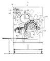
以下、実施の形態について図面を参照して説明する。図1に示すフィルム貼付装置の一態様であるラベリング装置1は、所定長さの感熱接着性ラベル(以下、ラベルという。)が連続的に繋がった長尺帯状のラベル形成基材Mを切断位置P1において順次切断することによって所定長さのラベルを形成しながら、そのラベルを、所定のラベル貼着位置P4に搬送されてくる、被貼付体としてのアルミニウム缶(以下、アルミ缶という。)Cの胴部外周面に巻き付けるようにして順次貼り付けていくものであり、前記ラベルは、厚さ12μm程度の薄肉で腰のないポリエチレンテレフタレートフィルムの内面に印刷を施し、感熱接着剤を塗布したものである。
【0010】
このラベリング装置1は、図1、図2及び図5に示すように、ロール状に巻回された長尺のラベル形成基材Mを切断位置P1に連続的に供給する一対の送給ローラ10と、この送給ローラ10によって供給されるラベル形成基材Mを第1受渡位置P2に搬送しながら、切断位置P1において所定のカットピッチで順次切断することによってラベルLを形成する切断搬送手段20と、ラベル貼付位置P4においてアルミ缶Cの胴部外周面にラベルLを貼り付けるラベル貼付手段40と、前記切断搬送手段20によってラベル形成基材Mから切断されたラベルLを第1受渡位置P2において受け取って第2受渡位置P3においてラベル貼付手段40に引き渡す受渡ドラム30と、前記ラベル貼付手段40にアルミ缶Cを供給する缶供給手段50と、前記ラベル貼付手段40によってラベルLが貼り付けられたアルミ缶Cを排出する缶排出手段60とから構成されている。
【0011】
前記切断搬送手段20は、図2に示すように、外周面に切断刃21aが取り付けられたロータリカッタ21と、送給ローラ10によって供給されるラベル形成基材Mを外周面に吸引保持して第1受渡位置P2まで搬送すると共にロータリカッタ21との協働作用によってラベル形成基材Mを所定長に順次切断する切断搬送ロール22とから構成されている。
【0012】
前記切断搬送ロール22は、同図に示すように、図示しない駆動手段によって回転駆動されるロール本体23と、このロール本体23が摺動可能に接触する固定部とから構成されており、前記ロール本体23の外周面には、その周方向に一定間隔で複数の貫通孔23aが形成されていると共に、固定部には、ロール本体23との接触面に、切断位置P1から第1受渡位置P2の手前までの間で前記貫通孔23aに連通する、図示しない吸引手段に接続された吸引溝24aと、第1受渡位置P2で前記貫通孔23aに連通する、図示しない吐出手段に接続された吐出溝24bとが形成されている。
【0013】
従って、切断位置P1に供給されるラベル形成基材Mは、吸引溝24aの吸引作用によって、回転(自転)するロール本体23の外周面に吸引保持された状態で第1受渡位置P2まで搬送される。ラベル形成基材Mが第1受渡位置P2に到達すると、貫通孔23aは吸引溝24aとの連通が遮断された後に吐出溝24bに連通されるので、吸引が一旦解除された後に、吐出溝24bの吐出作用によって、ロール本体23の外周面から空気が吐出され、ロール本体23の外周面に吸引保持されていたラベル形成基材Mがロール本体23から離反して後述する受渡ドラム30の外周面に強制的に押し当てられ、受渡ドラム30の外周面に吸引保持される。
【0014】
このようにしてラベル形成基材Mの先端部分が受渡ドラム30に引き渡された後に、ロータリカッタ21と切断搬送ロール22とによってラベル形成基材Mが切断されることでラベルLが形成され、形成されたラベルLが受渡ドラム30に引き渡される。
【0015】
前記受渡ドラム30は、図2に示すように、外周面が第1受渡位置P2において切断搬送ロール22の外周面に近接すると共に第2受渡位置P3において前記ラベル貼付手段40の貼付ドラム41の外周面に近接するように設置されており、切断搬送ロール22より大きな周速で切断搬送ロール22とは逆方向に回転(自転)するようになっている。
【0016】
この受渡ドラム30は、図示しない駆動手段によって回転駆動されるドラム本体31と、このドラム本体31が摺動可能に接触する固定部33とから構成されており、前記ドラム本体31の外周面には、テフロンコーティング等を施すことにより良好な滑り性を確保している。
【0017】
ラベル形成基材Mの先端部分が第1受渡位置P2において受渡ドラム30に引き渡された後、ラベル形成基材Mが切断されるまでの間は、切断搬送ロール22より周速の大きい受渡ドラム30によってラベル形成基材Mが引っ張られるが、この受渡ドラム30は、上述したように、その外周面が良好な滑り性を備えているため、受渡ドラム30の外周面に吸引保持されたラベル形成基材Mがその外周面上を容易に滑ることができる。従って、ラベル形成基材Mが受渡ドラム30に引き渡された後切断されるまでの間に、ラベル形成基材Mに過大なテンションがかかることがなく、形成されたラベルLにテンション皺が発生することもない。
【0018】
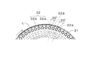
前記ドラム本体31には、その外周面に開放される多数の貫通孔32が外周面の周方向及び幅方向に一定間隔で整列するように形成されており、幅方向の各孔列を構成する複数の貫通孔32が相互に連通された状態で、前記固定部33との接触面に開放されている。
【0019】
前記貫通孔32は、図3に示すように、第1受渡位置P2において引き渡されるラベル形成基材M(ラベルL)の先端部分と接触する位置に対応するように形成された吸引吐出孔32aと、それ以外の位置に形成された吸引孔32bとから構成されており、前記吸引吐出孔32aは、ドラム本体31の径方向に対してドラム本体31の移動方向前方側(ラベルLの移動方向前方側)に30度傾斜した状態で形成されていると共に、前記吸引孔32bはドラム本体31の径方向に沿うように形成されている。
【0020】
前記固定部33には、ドラム本体31との接触面に、第1受渡位置P2から第2受渡位置P3の手前までの間で前記吸引吐出孔32a及び吸引孔32bに連通する吸引溝33aと、第2受渡位置P3で吸引吐出孔32aにのみ連通する吐出溝33bとが形成されており、この吸引溝33a及び吐出溝33bはそれぞれ図示しない吸引手段及び吐出手段に接続されている。
【0021】
従って、第1受渡位置P2において切断搬送手段20から引き渡されたラベルLは、吸引溝33aの吸引作用によってドラム本体31の外周面に吸引保持された状態で第2受渡位置P3まで搬送されるが、第2受渡位置P3では吸引が一旦解除され、上述したように、吸引吐出孔32aが吐出溝33bに連通することで、吸引吐出孔32aを介してドラム本体31の外周面から空気が吐出される。これによって、ドラム本体31の外周面に吸引保持されていたラベルLの先端部が外周面から離反して強制的に貼付ドラムの外周面に押し当てられることになる。
【0022】
吸引吐出孔32aは、上述したように、ドラム本体31の移動方向前方側に30度傾いた状態で形成されているので、第2受渡位置P3において吐出される空気は、図4に示すように、ラベルLの移動方向前方側に向かって吐出されることになる。従って、同図に示すように、ラベルLに吹き付けられた空気がラベルLの移動方向後方側に回り込みにくくなり、受け渡そうとするラベルLが薄肉で腰のないラベルであっても、受け渡しの際にラベルLの先端部が弛んだ状態とならず、受渡ドラム30の外周面と貼付ドラム41の外周面とを結ぶ直線上を通過するようにラベルLの受け渡しが行われる。これによって、ラベルLが貼付ドラム41の所定位置に確実に受け渡されると共に受け渡されたラベルLの先端部が部分的に浮き上がった状態で吸引保持されることもない。
【0023】
なお、このラベリング装置1では、吸引吐出孔32aの形成角度(空気の吐出角度)を受渡ドラム30の径方向に対して30度に設定してあるが、その形成角度(空気の吐出角度)は20〜60度、より好ましくは30〜45度の範囲内で適宜設定すればよい。形成角度が20度より小さいとたるみ防止効果が発揮されず、形成角度が60度より大きいとラベルLを貼付ドラム41に円滑に引き渡すことができないからである。
【0024】
また、このラベリング装置1では、ラベルLの先端部分についてのみ空気を吹き付けるようにしているが、ラベルLの先端から後端までの全長にわたって空気を吹き付けるようにすることも可能である。但し、その場合は、ラベルLの先端部分に対応する貫通孔32だけではなく、全ての貫通孔32を受渡ドラム30の径方向に対してラベルLの移動方向の前方側に傾けておくことが望ましい。
【0025】
前記ラベル貼付手段40は、図1及び図5に示すように、第2受渡位置P3において受け渡されたラベルLを外周面に吸引保持して貼付位置P4まで搬送する貼付ドラム41と、この貼付ドラム41による搬送途中でラベルLを予備的に加熱する輻射熱ヒータ(近赤外線ヒータ)42と、缶供給位置P5において前記缶供給手段50によって供給されたアルミ缶Cを、貼付位置P4を通過するように缶排出位置P6まで搬送する、アルミ缶Cの内寸と略同寸法の外周形状を有する金属製の多数のマンドレル43と、各マンドレル43に対応してそれぞれ設けられた輻射熱ヒータ(遠赤外線ヒータ)44と、缶供給位置P5から貼付位置P4までの間に固定設置された輻射熱ヒータ(遠赤外線ヒータ)45と、貼付位置P4においてアルミ缶Cに貼り付けられたラベルLを再加圧するガイド部材46とから構成されている。
【0026】
前記貼付ドラム41は、上述した受渡ドラム30と同様に、図示しない駆動手段によって回転駆動されるドラム本体41a(図2参照)と、このドラム本体41aが摺動可能に接触する固定部(図示せず)とから構成されており、前記ドラム本体41aの外周面はゴム等の弾性部材によって覆われている。
【0027】
また、ドラム本体41aは、上述した受渡ドラム30と同様に、その外周面に開放される多数の吸引孔41bが外周面の周方向及び幅方向に一定間隔で整列するように形成されており(図2参照)、幅方向の各孔列を構成する複数の吸引孔41bが相互に連通した状態で、前記固定部との接触面に開放されている。
【0028】
前記固定部は、ドラム本体41aとの接触面に、第2受渡位置P3から貼付位置P4までの間で前記吸引孔41bに連通する吸引溝(図示せず)が形成されており、この吸引溝は図示しない吸引手段に接続されている。従って、第2受渡位置P3において受渡ドラム30から受け渡されたラベルLは、ドラム本体41aの外周面に吸引保持された状態で貼付位置P4まで搬送される。
【0029】
前記マンドレル43は、図示しない駆動手段の回転駆動力によって、缶供給位置P5、貼付位置P4及び缶排出位置P6を通るような円軌道を自転しながら移動するようになっており、缶供給位置P5において嵌挿されたアルミ缶Cを貼付位置P4まで搬送し、貼付位置P4において、自転しているアルミ缶Cを貼付ドラム41の外周面に吸引保持されたラベルLに押し当てながら貼付ドラム41の外周面に沿って所定の距離だけ移動させることで、アルミ缶Cの胴部外周面にラベルLを貼り付けた後、アルミ缶Cを前記缶排出位置P6まで搬送するようになっている。
【0030】
前記輻射熱ヒータ44は、マンドレル43の回転軌道の内側において、その加熱面が各マンドレル43の外周面とそれぞれ対向するように、各マンドレル43の支持部材43aにそれぞれ支持されており、各マンドレル43と共に缶供給位置P5、貼付位置P4及び缶排出位置P6を通るような円軌道を移動するようになっている。
【0031】
前記輻射熱ヒータ45は、缶供給位置P5から貼付位置P4の間で、その加熱面がマンドレル43の外周面と対向するように、マンドレル43の移動経路に沿ってその外側に固定設置されており、マンドレル43に嵌挿されたアルミ缶Cをマンドレル43の移動経路の外側から加熱するようになっている。
【0032】
従って、アルミ缶Cがマンドレル43に嵌挿されていない缶排出位置P6から缶供給位置P5までの間は、輻射熱ヒータ44によってマンドレル43が加熱されることでマンドレル43が昇温され、缶供給位置P5において、昇温されたマンドレル43にアルミ缶Cが嵌挿されることで、マンドレル43の熱がアルミ缶Cに伝達され、アルミ缶Cが昇温される。
【0033】
次に、アルミ缶Cがマンドレル43に嵌挿された状態で缶供給位置P5から貼付位置P4まで搬送される間は、アルミ缶Cが輻射熱ヒータ44、45によって2方向から直接加熱されることでさらに昇温され、所定の貼付温度にまで昇温された状態でアルミ缶Cが貼付位置P4に供給される。
【0034】
そして、貼付位置P4においてマンドレル43に嵌挿されたアルミ缶CにラベルLが貼り付けられた後缶排出位置P6まで搬送される間は、輻射熱ヒータ44によってアルミ缶Cに貼り付けられたラベルLが直接加熱される。
【0035】
なお、缶供給位置P5から缶排出位置P6までの間は、マンドレル43自体が自転しているので、アルミ缶Cやアルミ缶Cに貼り付けられたラベルLが輻射熱ヒータ44、45によって部分的に加熱されることはなく、アルミ缶C及びラベルLは常に均一に加熱される。
【0036】
前記ガイド部材46は、貼付位置P4と缶排出位置P6との間におけるマンドレル43の回転軌道に沿ってその外側に配設されるゴム等の弾性部材によって形成された加圧板46aと、この加圧板46aを加熱する加熱ヒータ46bとから構成されており、貼付位置P4においてラベルLが貼り付けられたアルミ缶Cは、缶排出位置P6に到るまでの間に、昇温された前記加圧板46aに押し付けられた状態で自転しながら移動することで、アルミ缶Cに対するラベルLの再加圧が行われる。なお、貼付位置P4から缶排出位置P6までの間は、上述したように、マンドレル43と共に移動する輻射熱ヒータ44によってラベルLが継続的に加熱された状態となっている。
【0037】
前記缶供給手段50は、図1に示すように、多数のアルミ缶Cを連続的に送り出す供給シュート51と、この供給シュート51によって送り出されたアルミ缶Cを所定のタイミングで缶供給位置P5に供給するスターホイール52とから構成されており、この缶供給手段50によって缶供給位置P5に供給されたアルミ缶Cは、図示しない嵌挿機構によってマンドレル43に嵌挿される。
【0038】
前記缶排出手段60は、図1に示すように、貼付位置P4においてラベルLが貼り付けられたアルミ缶Cを、缶排出位置P6において所定のタイミングで受け取るスターホイール61と、このスターホイール61によって受け取ったアルミ缶Cを排出する排出シュート62とから構成されており、マンドレル43によって缶排出位置P6に搬送されてきたアルミ缶Cは、図示しない抜取機構によってマンドレル43から抜き取られた後、缶排出手段60によって排出される。
【0039】
以上のように、このラベリング装置1では、貼付位置P4においてアルミ缶Cに貼り付けられたラベルLをガイド部材46によって再加圧するような構成を採用しているので、貼付位置P4においてラベルLがアルミ缶Cに対して完全に接着されなかった場合でも、その後の再加圧によってラベルLをアルミ缶Cに強固に接着することができる。
【0040】
また、このラベリング装置1では、ガイド部材46の加圧板46aを加熱ヒータ46bによって加熱することで加圧板46aを所定温度にまで昇温するようにしているので、貼付位置P4におけるラベルLの貼り付けに際して接着不良が発生しても、昇温された加圧板46aによって再加圧することで、その接着不良を確実に解消することができる。従って、貼付位置P4において、アルミ缶Cに対するラベルLの接着を必ずしも完全に行う必要はなく、貼付位置P4におけるアルミ缶Cの温度を低めに設定することが可能となる。これによって、ラベルLをアルミ缶Cに貼り付ける際に、ラベルLがアルミ缶Cの熱によって不適切に軟化することがなくなり、従来、アルミ缶等の金属缶にラベルを貼り付ける際にラベルが軟化することに伴って発生していたラベル表面の波打ち状態を有効に防止することができる。
【0041】
さらに、このラベリング装置1では、貼付位置P4から缶排出位置P6までの間で、上述したガイド部材46によってラベルLをアルミ缶Cの胴部外周面に再加圧する場合にも、各マンドレル43に対して個別に設けられた輻射熱ヒータ44によってラベルLを継続的に加熱するようにしているので、加圧板46aの温度をそれほど高くしなくても、ガイド部材46によるラベルLの再加圧を効率よく行うことができるといった効果がある。また、このラベリング装置1では、マンドレル43の回転軌道上に貼付位置P4と加圧板46aとが設けられているため、装置全体が小型化され、省スペースで設置可能となる。
【0042】
また、この実施形態では、薄肉のポリエチレンテレフタレートフィルムによって形成された感熱接着性ラベルLを貼り付ける場合について説明したが、ポリエチレンテレフタレートフィルム以外にポリプロピレンフィルム等の種々の合成樹脂フィルムによって形成された感熱接着性ラベルを使用することが可能であり、ラベル以外の種々のフィルムの貼り付けについても適用することができることはいうまでもない。
【0043】
また、この実施形態では、ラベルLをアルミ缶Cに貼り付ける場合について説明したが、被貼付体はアルミ缶Cに限定されるものではなく、例えば、スチール缶等の種々の金属缶について適用することが可能である。
【図面の簡単な説明】
【図1】この発明にかかるラベリング装置(フィルム貼付装置)の一実施形態を示す正面図である。
【図2】同上のラベリング装置における切断搬送手段及び受渡ドラムを示す概略構成図である。
【図3】同上のラベリング装置における受渡ドラムを示す部分拡大図である。
【図4】同上のラベリング装置における受渡ドラムから貼付ドラムへのラベルの受渡状態を概念的に示す図である。
【図5】同上のラベリング装置における貼付手段を示す正面図である。
【図6】従来例を示す概略構成図である。
【符号の説明】
1 ラベリング装置
10 送給ローラ
20 切断搬送手段
30 受渡ドラム
40 貼付手段
41 貼付ドラム
43 マンドレル
44、45 輻射熱ヒータ
46 ガイド部材
46a 加圧板
46b 加熱ヒータ
50 缶供給手段
60 缶排出手段
M ラベル形成基材
L 感熱接着性ラベル
P4 貼付位置[0001]
BACKGROUND OF THE INVENTION
The present invention relates to a film sticking apparatus that transports a metal can to a sticking position while heating, and sticks a heat-sensitive adhesive film transported to the sticking position to a heated metal can.
[0002]
[Prior art]
As a film sticking device for attaching a film to the outer peripheral surface of a body portion of a metal can such as an aluminum can or a steel can, there is a labeling device as shown in FIG. The
[0003]
[Problems to be solved by the invention]
By the way, in the
[0004]
Further, in order to improve the adhesion failure of the label L to the metal can C due to insufficient press contact time at the pasting position β, the temperature of the metal can C at the pasting position β can be increased, It is conceivable to increase the pressing force of the metal can C against the label L. However, if the temperature of the metal can C is too high, the label L softens, and if the pressing force of the metal can C is too high, the
[0005]
Then, the subject of this invention is providing the film sticking apparatus which can adhere | attach a film firmly to a metal can even when sticking a film to a metal can at high speed.
[0006]
[Means for solving the problems and effects thereof]
In order to solve the above-mentioned problem, the invention according to
[0007]
In the film sticking device configured as described above, the heat-sensitive adhesive film attached to the metal can at the attaching position is equal to or more than the entire length of the heat-sensitive adhesive film installed along the mandrel moving path after the attaching position. since such pressure again pressurizing the metal can by pressing plate having a length, also as an adhesive failure occurs during pasting sensitive adhesive film in the attaching position, sufficient by recompression by subsequent pressing body It becomes possible to ensure the adhesive strength.
[0008]
In particular, as in the film sticking apparatus of the invention according to claim 2, wherein the apparatus having provided a heating means for heating the pressure plate, adhesive failure occurs when pasting sensitive adhesive film in the attaching position also, since it is possible to eliminate with certainty by re-pressurize the pressure plate which is heated its adhesion failure, it is not always necessary to completely perform the adhesion of the heat-sensitive adhesive film for a metal can in the attaching position. Therefore, it is possible to set the temperature of the metal can at a lower position, and when the heat-sensitive adhesive film is attached to the metal can, the heat-sensitive adhesive film is softened by the heat of the metal can. It is possible to effectively prevent the surface of the heat-sensitive adhesive film from wavy.
[0009]
DETAILED DESCRIPTION OF THE INVENTION
Hereinafter, embodiments will be described with reference to the drawings. A
[0010]
As shown in FIGS. 1, 2, and 5, the
[0011]
As shown in FIG. 2, the cutting / conveying means 20 sucks and holds the
[0012]
As shown in the figure, the cutting /
[0013]
Therefore, the label forming substrate M supplied to the cutting position P1 is conveyed to the first delivery position P2 while being sucked and held on the outer peripheral surface of the rotating
[0014]
After the leading end portion of the label forming base material M is transferred to the
[0015]
As shown in FIG. 2, the
[0016]
The
[0017]
After the leading end portion of the label forming substrate M is delivered to the
[0018]
The
[0019]
As shown in FIG. 3, the through-
[0020]
The fixing
[0021]
Accordingly, the label L delivered from the cutting and conveying
[0022]
As described above, since the suction /
[0023]
In this
[0024]
Further, in this
[0025]
As shown in FIGS. 1 and 5, the label sticking means 40 includes a sticking
[0026]
Similar to the
[0027]
In addition, the drum body 41a is formed so that a large number of
[0028]
The fixing portion is formed with a suction groove (not shown) communicating with the
[0029]
The
[0030]
The
[0031]
The
[0032]
Accordingly, during the period from the can discharge position P6 where the aluminum can C is not inserted into the
[0033]
Next, while the aluminum can C is being inserted into the
[0034]
The label L attached to the aluminum can C by the
[0035]
Since the
[0036]
The
[0037]
As shown in FIG. 1, the can supply means 50 has a
[0038]
As shown in FIG. 1, the
[0039]
As described above, in the
[0040]
Further, in this
[0041]
Furthermore, in this
[0042]
Moreover, in this embodiment, although the case where the heat-sensitive adhesive label L formed with the thin polyethylene terephthalate film was affixed was demonstrated, the heat-sensitive adhesion formed with various synthetic resin films, such as a polypropylene film, other than a polyethylene terephthalate film Needless to say, it is possible to use sex labels, and it is also possible to apply various types of films other than labels.
[0043]
Moreover, although this embodiment demonstrated the case where the label L was affixed on the aluminum can C, a to-be-adhered body is not limited to the aluminum can C, For example, it applies to various metal cans, such as a steel can. It is possible.
[Brief description of the drawings]
FIG. 1 is a front view showing an embodiment of a labeling device (film sticking device) according to the present invention.
FIG. 2 is a schematic configuration diagram showing a cutting and conveying means and a delivery drum in the labeling device same as above.
FIG. 3 is a partially enlarged view showing a delivery drum in the same labeling apparatus.
FIG. 4 is a diagram conceptually showing a label delivery state from a delivery drum to a sticking drum in the labeling device same as above.
FIG. 5 is a front view showing sticking means in the labeling device same as above.
FIG. 6 is a schematic configuration diagram showing a conventional example.
[Explanation of symbols]
DESCRIPTION OF
Claims (2)
前記貼付位置では、前記マンドレルに嵌挿された前記金属缶を、前記貼付ドラムの外周面に吸引保持された前記感熱接着性フィルムに押し当てながら前記貼付ドラムの外周面に沿って移動させることで、前記金属缶に前記感熱接着性フィルムを貼り付けるようになっており、
前記貼付位置以降の前記マンドレルの移動経路に沿って、前記感熱接着性フィルムの全長以上の長さを有する加圧板を設置し、前記貼付位置において前記フィルムが貼り付けられた前記金属缶を、前記加圧板に押し付けた状態で自転させながら移動させることで、前記金属缶に貼り付けられた前記感熱接着性フィルムを前記金属缶に対して再加圧するようにしたことを特徴とするフィルム貼付装置。A film that heats a metal can inserted in a mandrel to a sticking position while heating, and affixes the heat-sensitive adhesive film that is transported to the sticking position while being sucked and held on the outer peripheral surface of the sticking drum to the metal can In the pasting device,
At the sticking position, the metal can inserted into the mandrel is moved along the outer peripheral surface of the sticking drum while being pressed against the heat-sensitive adhesive film sucked and held on the outer peripheral surface of the sticking drum. The heat-sensitive adhesive film is attached to the metal can,
Along the path of movement of said mandrel after the sticking position, the installed heat-sensitive adhesive pressure plate having a length more than the total length of the film, the metal can in which the film is pasted at the sticking position, A film sticking device, wherein the heat-sensitive adhesive film attached to the metal can is re -pressurized against the metal can by moving while rotating while being pressed against the pressure plate. .
Priority Applications (2)
| Application Number | Priority Date | Filing Date | Title |
|---|---|---|---|
| JP03367199A JP4152030B2 (en) | 1999-02-12 | 1999-02-12 | Film sticking device |
| PCT/JP2000/005431 WO2002014159A1 (en) | 1999-02-12 | 2000-08-11 | Film pasting device |
Applications Claiming Priority (2)
| Application Number | Priority Date | Filing Date | Title |
|---|---|---|---|
| JP03367199A JP4152030B2 (en) | 1999-02-12 | 1999-02-12 | Film sticking device |
| PCT/JP2000/005431 WO2002014159A1 (en) | 1999-02-12 | 2000-08-11 | Film pasting device |
Publications (2)
| Publication Number | Publication Date |
|---|---|
| JP2000229359A JP2000229359A (en) | 2000-08-22 |
| JP4152030B2 true JP4152030B2 (en) | 2008-09-17 |
Family
ID=26344927
Family Applications (1)
| Application Number | Title | Priority Date | Filing Date |
|---|---|---|---|
| JP03367199A Expired - Fee Related JP4152030B2 (en) | 1999-02-12 | 1999-02-12 | Film sticking device |
Country Status (2)
| Country | Link |
|---|---|
| JP (1) | JP4152030B2 (en) |
| WO (1) | WO2002014159A1 (en) |
Families Citing this family (4)
| Publication number | Priority date | Publication date | Assignee | Title |
|---|---|---|---|---|
| JP4609872B2 (en) * | 2001-02-23 | 2011-01-12 | 大和製罐株式会社 | Manufacturing method of printed film sticking can |
| EP1449538A1 (en) | 2003-02-21 | 2004-08-25 | Max-Planck-Gesellschaft zur Förderung der Wissenschaften e.V. | Inhibition of TACE or amphiregulin for the modulation of EGF receptor signal transactivation |
| JP5919601B2 (en) * | 2012-06-21 | 2016-05-18 | 株式会社フジシール | Label mounting device |
| DE102012212491A1 (en) * | 2012-07-17 | 2014-01-23 | Krones Ag | Device for applying plastic labels on e.g. polyethylene terephthalate bottles, has hold-down attachment provided in conveying direction of label, where label and container to be labeled are pressed together for fastening label at container |
Family Cites Families (2)
| Publication number | Priority date | Publication date | Assignee | Title |
|---|---|---|---|---|
| JPS59209823A (en) * | 1983-05-16 | 1984-11-28 | Kishimoto Akira | Method for bonding piece of film |
| JP3394992B2 (en) * | 1994-03-02 | 2003-04-07 | 邦元 横塚 | Heating and pressing mechanism in secret label sticking device |
-
1999
- 1999-02-12 JP JP03367199A patent/JP4152030B2/en not_active Expired - Fee Related
-
2000
- 2000-08-11 WO PCT/JP2000/005431 patent/WO2002014159A1/en active Application Filing
Also Published As
| Publication number | Publication date |
|---|---|
| JP2000229359A (en) | 2000-08-22 |
| WO2002014159A1 (en) | 2002-02-21 |
Similar Documents
| Publication | Publication Date | Title |
|---|---|---|
| JP2567562B2 (en) | Non-peeling paper label processing apparatus and processing method thereof | |
| JP3602786B2 (en) | Label sticking method and label sticking device | |
| TWI344933B (en) | Conveyance drum, labeled container manufacturing method and labeled container manufacturing device | |
| US6378590B1 (en) | Hot gas label applicator | |
| US5480502A (en) | Method and apparatus for applying labels to articles using cooling air on label receiving positions | |
| JP2001514998A (en) | Method and apparatus for labeling a cylindrical article with a label having a formed curl | |
| US6514373B1 (en) | Labeling method employing radiation curable adhesive | |
| JPH0360728B2 (en) | ||
| JP4152030B2 (en) | Film sticking device | |
| JP4152029B2 (en) | Film sticking device | |
| WO2010016187A1 (en) | Labeling device | |
| JP3036724B2 (en) | Labeling equipment | |
| JP5293032B2 (en) | Label | |
| JP5912381B2 (en) | Label | |
| JP4152031B2 (en) | Film sticking device | |
| JP4152033B2 (en) | Film sticking device | |
| JP4152032B2 (en) | Film delivery mechanism and film sticking apparatus equipped with the film delivery mechanism | |
| JP4644310B1 (en) | Labeling machine | |
| JP4113364B2 (en) | Label sticking system | |
| JP3067413B2 (en) | Roll Labeler | |
| JP5610139B2 (en) | Method and apparatus for attaching film label to can body | |
| JP3730303B2 (en) | How to attach the label | |
| JP6234656B2 (en) | Label sticking device | |
| USRE23512E (en) | Labels to articles on a conveyer | |
| JP4511651B2 (en) | Film loading device |
Legal Events
| Date | Code | Title | Description |
|---|---|---|---|
| A621 | Written request for application examination |
Free format text: JAPANESE INTERMEDIATE CODE: A621 Effective date: 20060127 |
|
| A977 | Report on retrieval |
Free format text: JAPANESE INTERMEDIATE CODE: A971007 Effective date: 20071108 |
|
| A131 | Notification of reasons for refusal |
Free format text: JAPANESE INTERMEDIATE CODE: A131 Effective date: 20071113 |
|
| A521 | Written amendment |
Free format text: JAPANESE INTERMEDIATE CODE: A523 Effective date: 20080109 |
|
| TRDD | Decision of grant or rejection written | ||
| A01 | Written decision to grant a patent or to grant a registration (utility model) |
Free format text: JAPANESE INTERMEDIATE CODE: A01 Effective date: 20080701 |
|
| A01 | Written decision to grant a patent or to grant a registration (utility model) |
Free format text: JAPANESE INTERMEDIATE CODE: A01 |
|
| A61 | First payment of annual fees (during grant procedure) |
Free format text: JAPANESE INTERMEDIATE CODE: A61 Effective date: 20080701 |
|
| R150 | Certificate of patent or registration of utility model |
Free format text: JAPANESE INTERMEDIATE CODE: R150 |
|
| FPAY | Renewal fee payment (event date is renewal date of database) |
Free format text: PAYMENT UNTIL: 20110711 Year of fee payment: 3 |
|
| FPAY | Renewal fee payment (event date is renewal date of database) |
Free format text: PAYMENT UNTIL: 20110711 Year of fee payment: 3 |
|
| S531 | Written request for registration of change of domicile |
Free format text: JAPANESE INTERMEDIATE CODE: R313531 |
|
| FPAY | Renewal fee payment (event date is renewal date of database) |
Free format text: PAYMENT UNTIL: 20110711 Year of fee payment: 3 |
|
| R350 | Written notification of registration of transfer |
Free format text: JAPANESE INTERMEDIATE CODE: R350 |
|
| FPAY | Renewal fee payment (event date is renewal date of database) |
Free format text: PAYMENT UNTIL: 20110711 Year of fee payment: 3 |
|
| FPAY | Renewal fee payment (event date is renewal date of database) |
Free format text: PAYMENT UNTIL: 20110711 Year of fee payment: 3 |
|
| FPAY | Renewal fee payment (event date is renewal date of database) |
Free format text: PAYMENT UNTIL: 20110711 Year of fee payment: 3 |
|
| FPAY | Renewal fee payment (event date is renewal date of database) |
Free format text: PAYMENT UNTIL: 20120711 Year of fee payment: 4 |
|
| FPAY | Renewal fee payment (event date is renewal date of database) |
Free format text: PAYMENT UNTIL: 20120711 Year of fee payment: 4 |
|
| FPAY | Renewal fee payment (event date is renewal date of database) |
Free format text: PAYMENT UNTIL: 20120711 Year of fee payment: 4 |
|
| FPAY | Renewal fee payment (event date is renewal date of database) |
Free format text: PAYMENT UNTIL: 20130711 Year of fee payment: 5 |
|
| R250 | Receipt of annual fees |
Free format text: JAPANESE INTERMEDIATE CODE: R250 |
|
| LAPS | Cancellation because of no payment of annual fees |