WO2023176085A1 - マルチコア光ファイバ、光コンバイナ、およびファイバ特性測定方法 - Google Patents
マルチコア光ファイバ、光コンバイナ、およびファイバ特性測定方法 Download PDFInfo
- Publication number
- WO2023176085A1 WO2023176085A1 PCT/JP2022/047220 JP2022047220W WO2023176085A1 WO 2023176085 A1 WO2023176085 A1 WO 2023176085A1 JP 2022047220 W JP2022047220 W JP 2022047220W WO 2023176085 A1 WO2023176085 A1 WO 2023176085A1
- Authority
- WO
- WIPO (PCT)
- Prior art keywords
- core
- cores
- refractive index
- optical fiber
- face
- Prior art date
- Legal status (The legal status is an assumption and is not a legal conclusion. Google has not performed a legal analysis and makes no representation as to the accuracy of the status listed.)
- Ceased
Links
Images




Classifications
-
- G—PHYSICS
- G01—MEASURING; TESTING
- G01M—TESTING STATIC OR DYNAMIC BALANCE OF MACHINES OR STRUCTURES; TESTING OF STRUCTURES OR APPARATUS, NOT OTHERWISE PROVIDED FOR
- G01M11/00—Testing of optical apparatus; Testing structures by optical methods not otherwise provided for
- G01M11/30—Testing of optical devices, constituted by fibre optics or optical waveguides
- G01M11/33—Testing of optical devices, constituted by fibre optics or optical waveguides with a light emitter being disposed at one fibre or waveguide end-face, and a light receiver at the other end-face
- G01M11/333—Testing of optical devices, constituted by fibre optics or optical waveguides with a light emitter being disposed at one fibre or waveguide end-face, and a light receiver at the other end-face using modulated input signals
-
- G—PHYSICS
- G01—MEASURING; TESTING
- G01M—TESTING STATIC OR DYNAMIC BALANCE OF MACHINES OR STRUCTURES; TESTING OF STRUCTURES OR APPARATUS, NOT OTHERWISE PROVIDED FOR
- G01M11/00—Testing of optical apparatus; Testing structures by optical methods not otherwise provided for
-
- G—PHYSICS
- G02—OPTICS
- G02B—OPTICAL ELEMENTS, SYSTEMS OR APPARATUS
- G02B6/00—Light guides; Structural details of arrangements comprising light guides and other optical elements, e.g. couplings
- G02B6/02—Optical fibres with cladding with or without a coating
- G02B6/02042—Multicore optical fibres
-
- G—PHYSICS
- G02—OPTICS
- G02B—OPTICAL ELEMENTS, SYSTEMS OR APPARATUS
- G02B6/00—Light guides; Structural details of arrangements comprising light guides and other optical elements, e.g. couplings
- G02B6/02—Optical fibres with cladding with or without a coating
- G02B6/028—Optical fibres with cladding with or without a coating with core or cladding having graded refractive index
- G02B6/0288—Multimode fibre, e.g. graded index core for compensating modal dispersion
-
- G—PHYSICS
- G02—OPTICS
- G02B—OPTICAL ELEMENTS, SYSTEMS OR APPARATUS
- G02B6/00—Light guides; Structural details of arrangements comprising light guides and other optical elements, e.g. couplings
- G02B6/02—Optical fibres with cladding with or without a coating
- G02B6/036—Optical fibres with cladding with or without a coating core or cladding comprising multiple layers
- G02B6/03605—Highest refractive index not on central axis
- G02B6/03611—Highest index adjacent to central axis region, e.g. annular core, coaxial ring, centreline depression affecting waveguiding
-
- G—PHYSICS
- G02—OPTICS
- G02B—OPTICAL ELEMENTS, SYSTEMS OR APPARATUS
- G02B6/00—Light guides; Structural details of arrangements comprising light guides and other optical elements, e.g. couplings
- G02B6/24—Coupling light guides
- G02B6/255—Splicing of light guides, e.g. by fusion or bonding
-
- G—PHYSICS
- G02—OPTICS
- G02B—OPTICAL ELEMENTS, SYSTEMS OR APPARATUS
- G02B6/00—Light guides; Structural details of arrangements comprising light guides and other optical elements, e.g. couplings
- G02B6/24—Coupling light guides
- G02B6/26—Optical coupling means
- G02B6/30—Optical coupling means for use between fibre and thin-film device
-
- G—PHYSICS
- G02—OPTICS
- G02B—OPTICAL ELEMENTS, SYSTEMS OR APPARATUS
- G02B6/00—Light guides; Structural details of arrangements comprising light guides and other optical elements, e.g. couplings
- G02B6/02—Optical fibres with cladding with or without a coating
- G02B6/036—Optical fibres with cladding with or without a coating core or cladding comprising multiple layers
- G02B6/03616—Optical fibres characterised both by the number of different refractive index layers around the central core segment, i.e. around the innermost high index core layer, and their relative refractive index difference
- G02B6/03622—Optical fibres characterised both by the number of different refractive index layers around the central core segment, i.e. around the innermost high index core layer, and their relative refractive index difference having 2 layers only
- G02B6/03627—Optical fibres characterised both by the number of different refractive index layers around the central core segment, i.e. around the innermost high index core layer, and their relative refractive index difference having 2 layers only arranged - +
-
- G—PHYSICS
- G02—OPTICS
- G02B—OPTICAL ELEMENTS, SYSTEMS OR APPARATUS
- G02B6/00—Light guides; Structural details of arrangements comprising light guides and other optical elements, e.g. couplings
- G02B6/02—Optical fibres with cladding with or without a coating
- G02B6/036—Optical fibres with cladding with or without a coating core or cladding comprising multiple layers
- G02B6/03616—Optical fibres characterised both by the number of different refractive index layers around the central core segment, i.e. around the innermost high index core layer, and their relative refractive index difference
- G02B6/03638—Optical fibres characterised both by the number of different refractive index layers around the central core segment, i.e. around the innermost high index core layer, and their relative refractive index difference having 3 layers only
- G02B6/0365—Optical fibres characterised both by the number of different refractive index layers around the central core segment, i.e. around the innermost high index core layer, and their relative refractive index difference having 3 layers only arranged - - +
-
- G—PHYSICS
- G02—OPTICS
- G02B—OPTICAL ELEMENTS, SYSTEMS OR APPARATUS
- G02B6/00—Light guides; Structural details of arrangements comprising light guides and other optical elements, e.g. couplings
- G02B6/04—Light guides; Structural details of arrangements comprising light guides and other optical elements, e.g. couplings formed by bundles of fibres
Definitions
- the present disclosure relates to a multi-core optical fiber (hereinafter referred to as "MCF"), an optical combiner, and a method for measuring fiber characteristics.
- MCF multi-core optical fiber
- This application claims priority from Japanese Patent Application No. 2022-042673 filed on March 17, 2022, relies on the contents thereof, and is incorporated herein by reference in its entirety.
- Patent Document 1 discloses a method for measuring MCF crosstalk (hereinafter referred to as "XT") using an OTDR (Optical Time Domain Reflectometer), and also uses an optical combiner to improve measurement efficiency. The points are disclosed.
- Patent Document 2 discloses a bundle type optical combiner (FIFO: FAN-IN/FAN-OUT) for few modes, in which four types of LP (Linearly Polarized) modes are guided through each core. A possible Few-mode MCF is connected.
- Patent Document 3 discloses an example of a single-core optical fiber (hereinafter referred to as "SCF”) that reduces splice loss with a GI (Graded-Index) type refractive index profile core. Note that the FIFO alone may be called an optical combiner, but in this specification, the term "optical combiner" includes the SCF and MCF for connection in addition to the FIFO.
- SCF single-core optical fiber
- Non-Patent Document 1 discloses a design of a non-coupled MCF in which nine types of LP modes can be guided through each core.
- Non-Patent Document 2 defines a method for measuring the cutoff wavelength of an SCF having a single mode core.
- Non-Patent Document 3 evaluates the characteristics of an MCF in which a plurality of cores each having a core diameter of 26 ⁇ m are arranged at a core pitch of 39 ⁇ m.
- the difference in refractive index between cores is 0.016, and each core has a GI type refractive index profile.
- each core can guide approximately nine types of LP modes.
- JP2012-202827A Japanese Patent Application Publication No. 2017-146354 Japanese Patent Application Publication No. 2009-258354
- the MCF of the present disclosure includes a plurality of cores extending along a central axis and a common cladding surrounding each of the plurality of cores, and at a wavelength of 1260 nm, 10 or more kinds of In the LP mode, waves are guided through each of the plurality of cores for 1 m or more.
- FIG. 1 is a diagram showing the basic structure of an MCF and an optical combiner according to the present disclosure.
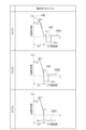
- FIG. 2 is a diagram for explaining the relative refractive index difference volume V.
- FIG. 3 is a diagram showing a measurement device and measurement results for measuring a cutoff wavelength as an example of a fiber characteristic to be measured.
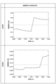
- FIG. 4 is a diagram showing the wavelength dependence of splice loss for various samples that do not satisfy the splice conditions required for the MCF of the present disclosure when measuring the cutoff wavelength.
- FIG. 5 is a diagram for explaining the XT conditions applied to the MCF of the present disclosure.
- FIG. 6 is a diagram showing a measuring device for measuring the wavelength dependence of transmission loss as an example of the fiber characteristics to be measured.
- connection loss between the optical combiner and the measurement target As described in Non-Patent Document 2, in the standard measurement method, the long wavelength side of the graph showing the measured value for each wavelength is A parallel line is drawn 0.1 dB above the line segment that is part of the graph, and the wavelength at the intersection of this parallel line and the graph is determined as the cutoff wavelength. Therefore, the connection loss when the measurement light enters and outputs the measurement target needs to be sufficiently smaller than 0.1 dB.
- the present disclosure has been made to solve the above-mentioned problems, and provides a structure for suppressing an increase in connection loss even when axis misalignment occurs between cores to be optically connected.
- the present invention aims to provide an MCF, an optical combiner including the MCF, and a method for measuring fiber characteristics using the MCF.
- the MCF of the present disclosure is (1) It may include a plurality of cores extending along the central axis and a common cladding surrounding each of the plurality of cores, and may have the following first structure.
- the first structure is defined by guiding ten or more types of LP modes, including the fundamental mode, through each of the plurality of cores for 1 m or more at a wavelength of 1260 nm.
- connection loss due to axis misalignment can be reduced by guiding ten or more types of LP modes, including higher-order modes in addition to the fundamental mode, for 1 m or more in each core.
- a state in which "LP mode is guided” means a state in which the transmission loss of the LP mode is 3.01 dB or less after propagating 1 m in the core to be guided.
- the "axis misalignment” state means a state where the central axes of both cores to be optically connected are separated by 1 ⁇ m or more, and the axis misalignment allowed in the MCF of the present disclosure is 5 ⁇ m or less.
- the MCF of the present disclosure may have the following second structure.
- the second structure can be combined with the first structure, and is defined by the relative refractive index difference volume V ( ⁇ m 2 ) of each of the plurality of cores, and the relative refractive index difference volume V ( ⁇ m 2 ) of each core is , is defined on the cross section of the MCF perpendicular to the central axis.
- the second structure is obtained by integrating the relative refractive index difference of the target core with respect to the lowest refractive index region within a reference cross section from the center of the target core to the lowest refractive index region included in the common cladding.
- the relative refractive index difference volume V ( ⁇ m 2 ) obtained has the following relationship: 2.2302 ⁇ V Defined by satisfying the following.
- This relational expression is a specific condition for guiding more than 10 types of LP modes, including higher-order modes in addition to the fundamental mode, in each core, and approximates the refractive index profile of the core to a step index type. This is a condition for the normalized frequency v_eff to be 8.6 or more when
- the MCF of the present disclosure may have the following third structure.
- the third structure has 13 or more types of LP modes. In this way, by guiding 13 or more types of LP modes, including not only the fundamental mode but also higher-order modes, for 1 m or more in each core, the connection loss due to axis misalignment can be further reduced.
- the mode group including 13 or more types of LP modes includes the mode group including the above-mentioned 10 or more types of LP modes.
- the "mode group" that comprehensively defines the modes guided in each core may include modes other than the LP mode.
- the MCF of the present disclosure may have the following fourth structure.
- the fourth structure can be combined with the third structure, and is defined by the relative refractive index difference volume V ( ⁇ m 2 ) of each of the plurality of cores, and the relative refractive index difference volume V ( ⁇ m 2 ) of each core is , is defined on the cross section of the MCF perpendicular to the central axis.
- the fourth structure is a relative refractive index obtained by integrating the relative refractive index difference of the target core with respect to the lowest refractive index region within the reference cross section from the center of the target core to the lowest refractive index region included in the common cladding.
- the rate difference volume V ( ⁇ m 2 ) has the following relationship: 2.9256 ⁇ V Defined by satisfying the following.
- This relational expression is a specific condition for guiding more than 13 types of LP modes, including higher-order modes in addition to the fundamental mode, in each core, and approximates the refractive index profile of the core to a step index type. This is a condition for the normalized frequency v_eff to be 9.85 or more when
- the MCF of the present disclosure is (5) It includes a plurality of cores extending along the central axis and a common cladding surrounding each of the plurality of cores, and has a structure defined by the relative refractive index difference volume V ( ⁇ m 2 ) of each of the plurality of cores. It's okay.
- the relative refractive index difference volume V ( ⁇ m 2 ) of each core is defined on the cross section of the MCF perpendicular to the central axis.
- the second structure is obtained by integrating the relative refractive index difference of the target core with respect to the lowest refractive index region within a reference cross section from the center of the target core to the lowest refractive index region included in the common cladding.
- the relative refractive index difference volume V ( ⁇ m 2 ) obtained has the following relationship: 2.2302 ⁇ V Defined by satisfying the following.
- This relational expression is a specific condition for guiding more than 10 types of LP modes, including higher-order modes in addition to the fundamental mode, in each core, and approximates the refractive index profile of the core to a step index type. This is a condition for the normalized frequency v_eff to be 8.6 or more when
- the relative refractive index difference volume V ( ⁇ m 2 ) has the following relationship: 2.9256 ⁇ V may be satisfied.
- This relational expression is a specific condition for guiding more than 13 types of LP modes, including higher-order modes in addition to the fundamental mode, in each core, and approximates the refractive index profile of the core to a step index type. This is a condition for the normalized frequency v_eff to be 9.85 or more when
- the relative refractive index difference volume V ( ⁇ m 2 ) may be 15 or less.
- the relative refractive index difference volume V ( ⁇ m 2 ) is 15 or less, more than necessary attenuation of the light intensity of light propagating within each core, for example, light used for measurement, is effectively suppressed.
- the relative refractive index difference volume V ( ⁇ m 2 ) may be 11 or less.
- the relative refractive index difference volume V ( ⁇ m 2 ) is 11 or less, more than necessary attenuation of light propagating within each core is more effectively suppressed.
- the first core and the second core satisfy the adjacency relationship with the shortest center-to-center distance ⁇ ( ⁇ m) among the plurality of cores, and the radius a(
- the first core having a radius b ( ⁇ m) and the second core having a radius b ( ⁇ m) have the following relationship: 34 ⁇ 46, 0.6375 ⁇ (a+b)/ ⁇ 0.8625 may be satisfied.
- the first core and the second core have the following relationship: 34 ⁇ 46, 0.675 ⁇ (a+b)/ ⁇ 0.825 may be satisfied.
- XT between adjacent cores can be effectively reduced.
- At least one of the plurality of cores may have a GI type refractive index profile.
- connection loss between cores to be optically connected can be effectively reduced.
- the MCF of the present disclosure is arranged so as to correspond one-to-one to each of the plurality of cores and to surround the outer periphery of a corresponding one of the plurality of cores.
- the semiconductor device may further include a plurality of trench portions. Each of the plurality of trench portions has a refractive index lower than the refractive index of the common cladding. In this case, it becomes possible to effectively reduce XT.
- the optical combiner of the present disclosure includes: (13) The MCF according to any one of (1) to (12) above may be provided.
- the optical combiner includes the MCF of the present disclosure and an optical waveguide device.
- the optical waveguide device includes a first end surface having a predetermined first core arrangement, a second end surface having a second core arrangement different from the first core arrangement, and provided between the first end surface and the second end surface. It has multiple cores. Further, in the first end surface, the plurality of cores between the first end surface and the second end surface are optically connected one-to-one to the plurality of cores of the MCF of the present disclosure.
- each of the plurality of cores of the optical waveguide device may be a multimode core.
- the fiber characteristic measuring method of the present disclosure includes: (14) To measure the cutoff wavelength as a fiber characteristic, prepare the MCF to be measured as the measurement target, prepare the first optical transmission line, configure the fiber line including the measurement target, and measure the intensity of the measurement light. Then, the cutoff wavelength of each of the plurality of cores to be measured is determined.
- the MCF to be measured which is the measurement target, has a first end surface and a second end surface, and has a plurality of cores each extending from the first end surface toward the second end surface.
- the first optical transmission line is arranged on the side of the first end face or the second end face of the object to be measured, and functions as an input side optical transmission line or an output side optical transmission line.
- the first optical transmission path includes a first MCF having the same structure as the MCF of the present disclosure described in any one of (1) to (12) above.
- the fiber line includes a first MCF and a measurement target, and is configured by optically connecting a plurality of cores of the first MCF and a plurality of cores of the measurement target one-to-one.
- the intensity of the measurement light that is input to the input side end face of the fiber line and then output from the output side end face of the fiber line is different from the wavelength of the measurement light. Measured while changing.
- the cutoff wavelength of each of the plurality of cores to be measured is determined based on the measurement results regarding the measured object.
- the measurement light is light that is input to each of the plurality of cores of the fiber line into the input side end face of the fiber line and then output from the output side end face of the fiber line.
- the intensity measurement for each wavelength in the plurality of cores to be measured may be performed simultaneously on the plurality of cores, or may be performed on each of the plurality of cores at different times.
- the cutoff wavelength of each of the plurality of cores to be measured is determined as a fiber characteristic based on the measurement results of the target to be measured.
- the first optical transmission line may have the same structure as the optical combiner in (13) above, as the optical combiner of the present disclosure.
- the first optical transmission line may be an optical combiner including a first MCF and a first optical waveguide device.
- the first optical waveguide device is provided between a first end face having a predetermined first core arrangement, a second end face having a second core arrangement different from the first core arrangement, and the first end face and the second end face. and a plurality of cores.
- the plurality of cores of the first optical waveguide device are optically connected one-to-one to the plurality of cores of the first MCF at the first end surface.
- the optical transmission line to which the same structure as the optical combiner of the present disclosure is not applied is such that the measurement light from the light source is treated as multimode light and is It is sufficient if the configuration is such that the light input to the core and from all the cores of the MCF to be measured can be received by the power meter as multimode light. More specifically, the measurement light may be input directly from the light source to all cores of the MCF to be measured, or may be input to all cores of the MCF to be measured directly from the light source, or may be input to a single-core large-diameter multimode optical fiber (hereinafter referred to as "MMF") or the measurement light according to the present disclosure.
- MMF single-core large-diameter multimode optical fiber
- the light output from all the cores of the MCF to be measured may be input directly to the power meter, or may be input to the power meter via a single-core large-diameter MMF or the MCF of the present disclosure.
- a second optical transmission line is further prepared, which is located on the opposite side of the measurement target from the first optical transmission line and functions as an input optical transmission line or an output optical transmission line. may be done.
- this second optical transmission path includes a second MCF having the same structure as any of the MCFs (1) to (12) above as the MCF of the present disclosure.
- the fiber line is configured by optically connecting the plurality of cores of the second MCF and the plurality of cores of the measurement object one-to-one so that the measurement object is sandwiched between the first MCF and the second MCF.
- the second optical transmission line may have the same structure as the optical combiner in (13) above.
- the second optical transmission line may be an optical combiner including a second MCF and a second optical waveguide device.
- the second optical waveguide device has the same structure as the first optical waveguide device, and has a first end surface having a predetermined first core arrangement, and a second end surface having a second core arrangement different from the first core arrangement. , a plurality of cores provided between the first end surface and the second end surface.
- the plurality of cores of the second optical waveguide device are optically connected one-to-one to the plurality of cores of the second MCF at the first end surface. In this case as well, it becomes possible to increase the degree of freedom in designing the measuring device that implements the fiber characteristic measuring method.
- the fiber characteristic measuring method of the present disclosure includes: (18) In order to measure the wavelength dependence of transmission loss by the cutback method as a fiber characteristic, prepare an MCF to be measured as the first measurement object, prepare an output side optical transmission line including the MCF of the present disclosure, A first fiber line including the entirety of one measurement object is constructed, and optical characteristics in each core of the first measurement object after cutback are determined.
- the MCF to be measured which is the first measurement target, has a first end surface and a second end surface, and has a plurality of cores each extending from the first end surface toward the second end surface.
- the output side optical transmission line is arranged on the second end surface side of the first measurement target, and includes any one of the MCFs (1) to (12) above as the MCF of the present disclosure.
- the first fiber line includes the MCF of the output side optical transmission line and the entire first measurement object, and optically connects the plurality of cores of the MCF and the plurality of cores of the first measurement object one-to-one. Consisted of. In such a configuration, a first measurement step for the first measurement object and a second measurement step for the second measurement object that is a part of the first measurement object are performed. Note that the second measurement target is a part of the first measurement target that is separated from the first measurement target and has a predetermined cutback length.
- the intensity of the measurement light that is input to the input side end face of the first fiber line and then output from the output side end face of the first fiber line is measured. be measured.
- the intensity of the measurement light is measured using a second fiber line that includes the second measurement target.
- the second measurement target is a part of the first measurement target that is separated from the first measurement target and has a predetermined cutback length.
- the second fiber line is a fiber line in which the first measurement object has been removed except for the second measurement object, and the MCF that was part of the first fiber line and the plurality of cores of the second measurement object are removed.
- It is constructed by optically connecting a plurality of cores one-to-one. After this second fiber line is configured, measurement light is input to the input side end face of the second fiber line and then output from the output side end face of the second fiber line for each core of the second fiber line. intensity is measured.
- the wavelength dependence of the transmission loss of each of the plurality of cores of the first measurement object after the second measurement object is separated is determined based on the measurement results of the first measurement step and the second measurement step described above. be done. Even with such a configuration, by using the MCF of the present disclosure, it is possible to measure the fiber characteristics of each core in the MCF to be measured without increasing connection loss between fibers.
- the output side optical transmission line may have the same structure as the optical combiner in (13) above.
- the output optical transmission line may be an optical combiner including an MCF and an optical waveguide device included in the output optical transmission line.
- the optical waveguide device includes a first end surface having a predetermined first core arrangement, a second end surface having a second core arrangement different from the first core arrangement, and provided between the first end surface and the second end surface. It has multiple cores. Further, the plurality of cores of this optical waveguide device are optically connected one-to-one to the plurality of cores of the MCF at the first end surface. In this case as well, it becomes possible to increase the degree of freedom in designing the measuring device.
- FIG. 1 is a diagram (denoted as "basic structure" in FIG. 1) showing the basic structure of an MCF and an optical combiner according to the present disclosure.
- MCF MCF
- FIG. 1 shows an example of the MCF 100 of the present disclosure in the upper part of FIG. 1 (denoted as "MCF” in FIG. 1).
- MCF MCF
- the number of cores in the MCF 100 may be two or more, and is not limited to the example shown in the upper part of FIG.
- an example including a FIFO device 210 as a multimode optical waveguide is shown as an example of the optical combiner 200 of the present disclosure.
- an element located on the input end side of the measurement target to which measurement light is input as the optical combiner 200 is referred to as an input-side optical combiner 200A
- an element located on the output end side of the measurement target is referred to as an output side optical combiner 200.
- the FIFO device included in the input-side optical combiner 200A as the FIFO device 210 is referred to as a FAN-IN device 210A
- the FIFO device included in the output-side optical combiner 200B is referred to as a FAN-OUT device 210B.
- the MCF 100 of the present disclosure shown in the upper part of FIG. 1 includes a glass optical fiber 110 having a first end surface 110a and a second end surface 110b, and a resin coating 130 provided on the outer peripheral surface of the glass optical fiber 110.
- the glass optical fiber 110 includes cores 111 to 114 extending from a first end face 110a to a second end face 110b along a fiber axis AX, which is a central axis, and a common cladding 120 surrounding each of the cores 111 to 114. and.
- the glass optical fiber 110 may include a plurality of trench portions 140 provided in one-to-one correspondence with each of the cores 111 to 114.
- Each of the plurality of trench portions 140 constitutes a part of the common cladding 120 and becomes the lowest relative refractive index region of the common cladding 120. That is, the refractive index of each trench portion 140 is lower than the refractive index of the common cladding 120 excluding the plurality of trench portions 140. In a configuration in which a plurality of trench portions 140 are not provided in the common cladding 120, the entire common cladding 120 becomes the lowest refractive index region.
- the optical combiner 200 of the present disclosure shown in the lower part of FIG. 1 includes a FIFO device 210 that functions as an optical waveguide device, a plurality of connection SCFs 230 each having a multimode core, and an MCF 100 of the present disclosure.
- the FIFO device 210 has a plurality of cores 220, and the plurality of cores 220 and the cores of the plurality of connecting SCFs 230 are optically connected one-to-one at the first end surface 210a of the FIFO device 210.
- the plurality of cores 220 and the cores 111 to 114 of the MCF 100 are optically connected one-on-one.
- FIG. 2 is a diagram for explaining the relative refractive index difference volume V (referred to as "refractive index profile" in FIG. 2).
- Refractive index profile in FIG. 2
- FIG. 2 shows the upper part of FIG. 2 indicated as “Type 1" in FIG. 2 in the upper part of FIG. 2 indicated as “Type 1" in FIG. 2 in the upper part of FIG. 1 in the upper part of FIG. 1 in the upper part of FIG. 1 .
- the middle part of FIG. 2 denoted as “Type 2" in FIG. 2
- an example of the refractive index profile 150B of the core and the core peripheral surface along the line L shown in the upper part of FIG. 1 is shown.
- the lower part of FIG. 2 shows the refractive index profile 150C of the core and the core peripheral surface along the line L shown in the upper part of FIG.
- the type 1 refractive index profile 150A shown in the upper part of FIG. 2 is an example in which a plurality of trench portions 140 are provided in one-to-one correspondence with each of the cores 111 to 114.
- each trench portion 140 forming a part of the common cladding 120 is arranged at a position away from the corresponding core among the cores 111 to 114. Further, each trench portion 140 is the lowest refractive index region included in the common cladding 120. Note that in the upper part of FIG. 2, an example of the GI type refractive index profile of each core is shown by a broken line.
- the type 2 refractive index profile 150B shown in the middle part of FIG. 2 is also an example in which a plurality of trench portions 140 are provided in one-to-one correspondence with each of the cores 111 to 114.
- each trench portion 140 forming part of common cladding 120 is in contact with a corresponding one of cores 111 to 114, unlike refractive index profile 150A.
- each trench portion 140 is the lowest refractive index region included in the common cladding 120.
- the type 3 refractive index profile 150C shown in the lower part of FIG. 2 is an example in which trench portions are not provided around each of the cores 111 to 114. That is, in refractive index profile 150C, unlike refractive index profile 150A and refractive index profile 150B described above, common cladding 120 is in direct contact with each of cores 111 to 114. In this refractive index profile 150C, the lowest refractive index region included in the common cladding 120 is the common cladding 120 itself.
- the relative refractive index difference volume V of each core will be explained using examples of three types of refractive index profiles from the type 1 refractive index profile 150A to the type 3 refractive index profile 150C as described above. Note that it is generally difficult to measure how many types of LP modes are guided in a multimode core. Therefore, the relative refractive index difference volume V is used as an alternative index for measuring the number of guided LP modes. Furthermore, the refractive index profiles 150A to 150C shown in FIG. 2 are just examples, and the relative refractive index difference volume V can be calculated even if the refractive index profiles have a different shape.
- the relative refractive index difference volume V is defined as the point where the relative refractive index difference is the smallest in the periphery of the target core or the region where the relative refractive index difference is the smallest in types 1 to 3 shown in FIG. 2 above.
- r min be the distance from the core center to the point closest to the core.
- the relative refractive index difference with respect to the refractive index of pure silica at the point of distance r min is ⁇ min
- the relative refractive index difference with respect to the refractive index of pure silica of the target core and the core periphery is a function of the distance r from the core center.
- ⁇ core is the relative refractive index difference of the target core with respect to the refractive index of pure silica
- ⁇ core is the relative refractive index difference of the target core with respect to the refractive index of pure silica.
- the relative refractive index difference volume V is calculated by the following formula (2), where ⁇ min and the core radius are r: It is expressed as
- ⁇ core is the largest relative refractive index difference between the target core and the refractive index of pure silica
- ⁇ core is the largest relative refractive index difference between the target core and the refractive index of pure silica around the core.
- the condition for 10 types of LP modes (including the fundamental mode) to be guided in the multimode core at a wavelength of 1260 nm is 2.2302 ⁇ V. Further, the condition for guiding 13 or more types of LP modes in the multimode core at a wavelength of 1260 nm is 2.9256 ⁇ V. Note that by satisfying the condition 2.2302 ⁇ V, the normalized frequency v_eff becomes 8.6 or more when the refractive index profile of the core is approximated to a step index type. By satisfying the condition 2.9256 ⁇ V, the normalized frequency v_eff becomes 9.85 or more when the refractive index profile of the core is approximated to a step index type.
- the MCF 100 of the present disclosure having the above-described structure can be applied to an optical waveguide for signal transmission, but can also be applied to other uses.
- various examples of the fiber characteristic measuring method of the present disclosure using the MCF 100 of the present disclosure will be described as other application examples. Specifically, the measurement of the cutoff wavelength and the measurement of the wavelength dependence of transmission loss will be explained for each core of the MCF to be measured.
- FIG. 3 is a diagram (denoted as "measurement of cutoff wavelength” in FIG. 3) showing a measuring device and measurement results for measuring the cutoff wavelength as an example of the fiber characteristics of the MCF to be measured. Note that in the upper part of FIG. 3 (indicated as “measuring device” in FIG. 3), a configuration example of a measuring device for measuring the cutoff wavelength of the measurement target is shown. The lower part of FIG. 3 (denoted as "measurement results" in FIG. 3) shows an example of the measurement results obtained by the measuring device shown in the upper part of FIG.
- the measurement device shown in the upper part of FIG. 3 includes a plurality of light sources 300 each outputting measurement light, a plurality of power meters 400, and an optical combiner 200A disposed on both the input side and the output side of a measurement object 500. and an optical combiner 200B. Both optical combiner 200A and optical combiner 200B have the structure shown in the lower part of FIG. Note that the measurement target 500 is an MCF to be measured, and both the optical combiner 200A and the optical combiner 200B are optical combiners of the present disclosure.
- the optical combiner 200A includes the MCF 100 of the present disclosure having multimode cores 111 to 114, a FAN-IN device 210A, and a plurality of connection SCFs 230 each having a multimode core.
- the second end surface 110b of the MCF 100 is connected to the input side end surface of the measurement object 500 in a state where each of the cores 111 to 114 is optically connected one-to-one with the core of the measurement object 500 at one fusion point A. has been done.
- the first end surface 110a of the MCF 100 is connected to the FAN-IN device 210A, with each of the cores 111 to 114 being optically connected one-to-one to the multimode core of the FAN-IN device 210A.
- the plurality of light sources 300 are arranged in one-to-one correspondence with each core of the measurement target 500, and a plurality of connection devices are arranged to optically connect the plurality of light sources 300 and the corresponding cores of the FAN-IN device 210A.
- An SCF 230 is arranged.
- the optical combiner 200B includes the MCF 100 of the present disclosure having multimode cores 111 to 114, a FAN-OUT device 210B, and a plurality of connection SCFs 230 each having a multimode core.
- the second end surface 110b of the MCF 100 is connected to the output side end surface of the measurement object 500 in a state where each of the cores 111 to 114 is optically connected one-to-one with the core of the measurement object 500 at the other fusion point A. has been done.
- the first end surface 110a of the MCF 100 is connected to the FAN-OUT device 210B, with each of the cores 111 to 114 being optically connected one-to-one to the multimode core of the FAN-OUT device 210B.
- the plurality of power meters 400 are arranged in one-to-one correspondence with each core of the measurement target 500, and the plurality of power meters 400 are arranged so as to optically connect the corresponding cores of the FAN-OUT device 210B.
- a connection SCF 230 is arranged.
- optical combiner 200A and the optical combiner 200B is replaced with a set of a general optical combiner (standard optical combiner) shown in the upper part of FIG. 6 and the lower part of FIG. 6 and the MCF 100 of the present disclosure.
- a standard optical combiner has a structure similar to the optical combiner 200 shown in the lower part of FIG. 1, and includes a FIFO device 610, a connection MCF 600, and a plurality of connection SCFs 620.
- each core of the FIFO device 610, each core of the MCF 600, and each core of the plurality of connection SCFs 620 are all single-mode cores.
- each core (target core) of the measurement target 500 is inputted to the optical combiner 200A from the light source 300, which is a variable length light source corresponding to the target core, and then transmitted through the target core.
- the intensity of the measurement light output from the second optical combiner 200B is measured while changing the wavelength of the measurement light.
- the cutoff wavelengths of all the cores of the object to be measured 500 are determined as fiber characteristics based on the measurement results of the object to be measured 500.
- the lower part of FIG. 3 shows the wavelength dependence of light intensity as a measurement result for one core that is the target core.
- FIG. 4 is a diagram showing the wavelength dependence of splice loss for various samples that do not satisfy the splice conditions required for the MCF of the present disclosure in measuring the cutoff wavelength (in FIG. 4, "wavelength dependence of splice loss") ).
- the 10th LP mode counting from the fundamental mode is cut off in the wavelength range of 1150 nm to 1175 nm, and the 10th LP mode with a wavelength of 1175 nm or more is cut off.
- the wavelength dependence of splice loss is shown in the case of an MCF that guides only nine types of LP modes in the wavelength range and an axis misalignment of 3 ⁇ m.
- the 13th LP mode counting from the fundamental mode is cut off in the wavelength range of 1225 nm to 1250 nm, and the wavelength range of 1250 nm or more is shown. shows the wavelength dependence of splice loss when there is an axis misalignment of 3 ⁇ m in an MCF that guides only 12 types of LP modes.
- the connection loss when inputting and outputting measurement light to and from the MCF to be measured which is the measurement target 500, needs to be at least 0.05 dB or less in total. That is, the connection loss at the fusion point A between the MCF to be measured and the MCF 100 of the present disclosure needs to be 0.025 dB or less as the first connection condition required for the MCF 100 of the present disclosure.
- the long wavelength section where nine or less types of LP modes are guided.
- the connection loss increases significantly, and the connection loss during input/output of measurement light exceeds 0.025 dB. Therefore, the condition that ten or more types of LP modes are guided can be the first connection condition required for the MCF 100 of the present disclosure.
- the cutoff wavelength standard is generally defined as 1260 nm or less in the ITU-T G652 standard, so an MCF that guides 10 or more types of LP modes at a wavelength of 1260 nm meets the specifications required for the MCF of this disclosure. There is one.
- the total connection loss during input and output of measurement light to and from the measurement target may be 0.025 dB or less. That is, the connection loss at the fusion point A between the MCF to be measured, which is the measurement target 500, and the MCF 100 of the present disclosure may be 0.0125 dB or less, as the second connection condition required for the MCF 100 of the present disclosure.
- the state in which "the LP mode is guided” means that the transmission loss of the target LP mode after the target LP mode propagates for 1 m in each core of the MCF 100 of the present disclosure, as described above. This means a state of 3.01 dB or less.
- the effect of reducing connection loss in the MCF under test when 10 types of LP modes or 13 types of LP modes are guided is as follows: Even if it is assumed that the power of the th LP mode is half, this can be sufficiently achieved. Further, the length of the MCF 100 of the present disclosure may be 1 m or more in practice.
- the condition for the MCF 100 of the present disclosure to obtain the desired technical effect is that the power attenuation when a plurality of LP modes propagates for 1 m is 50% or less, that is, the transmission loss is 3.01 dB or less. This can be the waveguide condition required for the MCF 100 of the present disclosure.
- FIG. 5 is a diagram for explaining the XT conditions applied to the MCF of the present disclosure (denoted as "crosstalk XT optimization" in FIG. 5). Note that in the upper part of FIG. 5 (denoted as “cross-sectional structure” in FIG. 5), a part of the cross section of the MCF 100 of the present disclosure perpendicular to the fiber axis AX is shown. The lower part of FIG. 5 (“XT characteristics" in FIG. 5) shows the (a+b)/ ⁇ dependence of XT loss at a wavelength of 1300 nm.
- a mechanism for reducing XT is required when ten or more types of LP modes are guided through each core of a multimode MCF.
- the distance ⁇ between the centers of adjacent cores is 34 ⁇ m or more and 46 ⁇ m or less, so it is necessary to suppress the core diameter to at least 46 ⁇ m or less.
- cores that are in an adjacent relationship in the MCF are defined as a relationship between two cores having the shortest center-to-center distance among a plurality of cores in the MCF. Therefore, since each core of the multi-mode MCF for reducing connection loss described in Patent Document 3 has a core diameter of 50 ⁇ m, it cannot be directly applied to the MCF of the present disclosure.
- the center-to-center distance ⁇ between adjacent cores is 34 ⁇ m or more and 46 ⁇ m or less, and the core arrangement condition (a+b)/ ⁇ is as follows: 0.675 ⁇ (a+b)/ ⁇ 0.825 may be satisfied.
- each parameter of the core arrangement condition (a+b)/ ⁇ is defined as shown in the upper part of FIG. That is, a is the radius of the core 111, and b is the radius of the core 112 adjacent to the core 111.
- ⁇ is the distance between the line segment connecting the center 111a of the core 111 and the center 112a of the core 112, that is, the distance between the centers of the core 111 and the core 112.
- the core propagation mode is smaller in the MCF with a smaller core diameter than in the case with a larger core diameter even if the amount of axis misalignment is the same. It becomes easier to couple power to a mode in which the electric field distribution spreads outside the core. Therefore, XT is likely to occur in MCFs with small core diameters.
- the core arrangement condition (a+b)/ ⁇ is large, the distance between the cores becomes narrower, so that XT is more likely to occur in this case as well.
- the above conditions are located between these two contradictory effects and are the optimal conditions for reducing XT. As shown in the lower part of FIG.
- (a+b)/ ⁇ may be in the range of 0.6375 or more and 0.8625 or less, or may be in the range of 0.675 or more and 0.825 or less.
- the range from 0.60 to 0.90 is a range of -0.15 or more and +0.15 or less with 0.75 as the standard.
- the range of 0.6375 or more and 0.8625 or less is ⁇ 0.15 ⁇ 3/4 or more and +0.15 ⁇ 3/4 or less based on 0.75.
- the range of 0.675 or more and 0.825 or less is a range of -0.15/2 or more and +0.15/2 or less based on 0.75.
- the relative refractive index difference volume V ( ⁇ m 2 ) may be 15 or less, or may be 11 or less.
- FIG. 6 is a diagram illustrating a measuring device for measuring the wavelength dependence of transmission loss as an example of the fiber characteristic to be measured (in FIG. 6, it is written as "measurement of wavelength dependence of transmission loss").
- the upper part of FIG. 6 (indicated as “measuring device (state 1)” in FIG. 6) shows the configuration of the device that performs measurement on the entire measurement object (first measurement object) as the first measurement step. has been done.
- the lower part of FIG. 6 indicated as “measuring device (state 2)" in FIG. 6
- a part of a predetermined cutback length (cutback part) separated from the first measurement object is shown.
- the configuration of an apparatus that performs measurement as a second measurement object is shown. Note that state 1 shown in the upper part of FIG. 6 and state 2 shown in the lower part of FIG. 6 have the same device configuration except for the measurement target.
- the measuring device shown in the upper part of FIG. 6 and the lower part of FIG. It includes a first optical combiner placed on the input side, and a second optical combiner 200B including the MCF 100 of the present disclosure placed on the output side of the measurement target 500 or cutback portion 500A.
- the measurement target 500 is an MCF to be measured, which is a first measurement target
- the cutback portion 500A is a part of the MCF to be measured, which is a second measurement target.
- the first optical combiner is a standard optical combiner
- the second optical combiner 200B is an optical combiner of the present disclosure).
- the first optical combiner has a structure similar to the optical combiner 200 shown in the lower part of FIG. 1, and includes a FIFO device 610 functioning as a FAN-IN device, an MCF 600 for connection, and a plurality of connection Each core of the FIFO device 610, each core of the MCF 600, and each core of the plurality of connection SCFs 620 are all single-mode cores.
- the second end surface 600b of the MCF 600 is connected to the input side end surface of the object to be measured 500, with each core of the MCF 600 being optically connected one-to-one to the core of the object to be measured 500.
- a first end surface 600a of the MCF 600 is connected to the FIFO device 610, with each core of the MCF 600 being optically connected one-to-one to the single mode core of the FIFO device 610.
- the plurality of light sources 300 are arranged in one-to-one correspondence with each core of the measurement target 500, and the plurality of connection SCFs 620 are arranged to optically connect the plurality of light sources 300 and the corresponding cores of the FIFO device 610. It is located.
- the second optical combiner 200B includes the MCF 100 of the present disclosure having multimode cores 111 to 114, a FAN-OUT device 210B, and a plurality of connection SCFs 230 each having a multimode core.
- the second end surface 110b of the MCF 100 is connected to the output side end surface of the object to be measured 500 at the fusion point A, with each of the cores 111 to 114 being optically connected one-to-one to the core of the object to be measured 500.
- the first end surface 110a of the MCF 100 is connected to the FAN-OUT device 210B, with each of the cores 111 to 114 being optically connected one-to-one to the multimode core of the FAN-OUT device 210B.
- the plurality of power meters 400 are arranged in one-to-one correspondence with each core of the measurement target 500, and the plurality of power meters 400 are arranged so as to optically connect the corresponding cores of the FAN-OUT device 210B.
- a connection SCF 230 is arranged.
- a first measurement step is performed with the measurement object 500 as the first measurement object.
- the device configuration shown in the lower part of FIG. A measurement step is performed.
- the input side end face of the cutback portion 500A is connected to the first optical combiner, and the output side end face of the cutback portion 500A is connected to the second end face of the MCF 100 of the present disclosure at the fusion point A. 110b.
- the intensity of the measurement light that is input to the first optical combiner and then output from the second optical combiner 200B via the measurement target 500 is measured.
- the wavelength dependence of the transmission loss of all the cores of the remaining part of the measurement object 500 after the cutback portion 500A is separated is determined as the fiber characteristic in the first measurement step and the second measurement step. It is determined based on the measurement results of the second measurement step.
- the measurement result of the first measurement step is intensity data of the measurement light output from each core of the measurement target 500.
- the measurement result of the second measurement step is intensity data of the measurement light output from each core of the cutback portion 500A.
- the second optical combiner 200B among the measurement devices shown in the upper part of FIG. 6 and the lower part of FIG. It is also possible to replace it with a general optical combiner, which is a standard optical combiner with a standard optical combiner.
- the MCF 100 of the present disclosure is arranged between the output side end surface of the measurement target 500 or the cutback portion 500A and the second end surface 600b of the MCF 600 of the replaced standard optical combiner.
- a mode group including the LP mode may be used. That is, the mode group may include modes other than the LP mode.
Landscapes
- Physics & Mathematics (AREA)
- General Physics & Mathematics (AREA)
- Optics & Photonics (AREA)
- Chemical & Material Sciences (AREA)
- Analytical Chemistry (AREA)
- Engineering & Computer Science (AREA)
- Plasma & Fusion (AREA)
- Dispersion Chemistry (AREA)
- Optical Couplings Of Light Guides (AREA)
Priority Applications (4)
| Application Number | Priority Date | Filing Date | Title |
|---|---|---|---|
| PCT/JP2023/009708 WO2023176798A1 (ja) | 2022-03-17 | 2023-03-13 | マルチコア光ファイバ、光コンバイナ、およびファイバ特性測定方法 |
| US18/846,341 US20250189717A1 (en) | 2022-03-17 | 2023-03-13 | Multicore optical fiber, optical combiner, and method of measuring fiber characteristics |
| JP2024508169A JPWO2023176798A1 (https=) | 2022-03-17 | 2023-03-13 | |
| CN202380025564.8A CN118891552A (zh) | 2022-03-17 | 2023-03-13 | 多芯光纤、光组合器及光纤特性测定方法 |
Applications Claiming Priority (2)
| Application Number | Priority Date | Filing Date | Title |
|---|---|---|---|
| JP2022-042673 | 2022-03-17 | ||
| JP2022042673 | 2022-03-17 |
Publications (1)
| Publication Number | Publication Date |
|---|---|
| WO2023176085A1 true WO2023176085A1 (ja) | 2023-09-21 |
Family
ID=88022734
Family Applications (2)
| Application Number | Title | Priority Date | Filing Date |
|---|---|---|---|
| PCT/JP2022/047220 Ceased WO2023176085A1 (ja) | 2022-03-17 | 2022-12-21 | マルチコア光ファイバ、光コンバイナ、およびファイバ特性測定方法 |
| PCT/JP2023/009708 Ceased WO2023176798A1 (ja) | 2022-03-17 | 2023-03-13 | マルチコア光ファイバ、光コンバイナ、およびファイバ特性測定方法 |
Family Applications After (1)
| Application Number | Title | Priority Date | Filing Date |
|---|---|---|---|
| PCT/JP2023/009708 Ceased WO2023176798A1 (ja) | 2022-03-17 | 2023-03-13 | マルチコア光ファイバ、光コンバイナ、およびファイバ特性測定方法 |
Country Status (4)
| Country | Link |
|---|---|
| US (1) | US20250189717A1 (https=) |
| JP (1) | JPWO2023176798A1 (https=) |
| CN (1) | CN118891552A (https=) |
| WO (2) | WO2023176085A1 (https=) |
Citations (7)
| Publication number | Priority date | Publication date | Assignee | Title |
|---|---|---|---|---|
| JP2011170336A (ja) * | 2010-01-22 | 2011-09-01 | Sumitomo Electric Ind Ltd | マルチコアファイバ |
| JP2012032524A (ja) * | 2010-07-29 | 2012-02-16 | Hitachi Cable Ltd | マルチコア光ファイバとそれを用いた軸合わせ方法 |
| US20140119701A1 (en) * | 2012-10-31 | 2014-05-01 | Corning Incorporated | Multimode optical fiber and systems comprising such fiber |
| WO2016157639A1 (ja) * | 2015-03-30 | 2016-10-06 | 住友電気工業株式会社 | 光ファイバの漏洩損失測定方法 |
| JP2017146354A (ja) * | 2016-02-15 | 2017-08-24 | 株式会社フジクラ | 光デバイス |
| JP2018138910A (ja) * | 2017-02-24 | 2018-09-06 | 株式会社フジクラ | マルチコアファイバの特性測定装置及び特性測定方法 |
| US20200183082A1 (en) * | 2016-11-04 | 2020-06-11 | Draka Comteq France | Coupled few mode fibers, and corresponding optical link and optical system |
Family Cites Families (5)
| Publication number | Priority date | Publication date | Assignee | Title |
|---|---|---|---|---|
| JPS62144110A (ja) * | 1985-12-18 | 1987-06-27 | Furukawa Electric Co Ltd:The | マルチコアフアイバの入出力方法 |
| FR2754354B1 (fr) * | 1996-10-08 | 1998-11-06 | France Telecom | Dispositif de connexion pour fibre optique multicoeur, a base d'elements optiques en espace libre |
| GB0211445D0 (en) * | 2002-05-18 | 2002-06-26 | Qinetiq Ltd | Fibre optic connector |
| CN103513337A (zh) * | 2012-06-28 | 2014-01-15 | 无锡万润光子技术有限公司 | 双芯光纤分路器及其制作方法 |
| JP5957718B2 (ja) * | 2014-04-24 | 2016-07-27 | 国立研究開発法人情報通信研究機構 | マルチコア・マルチモードファイバ結合装置 |
-
2022
- 2022-12-21 WO PCT/JP2022/047220 patent/WO2023176085A1/ja not_active Ceased
-
2023
- 2023-03-13 CN CN202380025564.8A patent/CN118891552A/zh active Pending
- 2023-03-13 WO PCT/JP2023/009708 patent/WO2023176798A1/ja not_active Ceased
- 2023-03-13 US US18/846,341 patent/US20250189717A1/en active Pending
- 2023-03-13 JP JP2024508169A patent/JPWO2023176798A1/ja active Pending
Patent Citations (7)
| Publication number | Priority date | Publication date | Assignee | Title |
|---|---|---|---|---|
| JP2011170336A (ja) * | 2010-01-22 | 2011-09-01 | Sumitomo Electric Ind Ltd | マルチコアファイバ |
| JP2012032524A (ja) * | 2010-07-29 | 2012-02-16 | Hitachi Cable Ltd | マルチコア光ファイバとそれを用いた軸合わせ方法 |
| US20140119701A1 (en) * | 2012-10-31 | 2014-05-01 | Corning Incorporated | Multimode optical fiber and systems comprising such fiber |
| WO2016157639A1 (ja) * | 2015-03-30 | 2016-10-06 | 住友電気工業株式会社 | 光ファイバの漏洩損失測定方法 |
| JP2017146354A (ja) * | 2016-02-15 | 2017-08-24 | 株式会社フジクラ | 光デバイス |
| US20200183082A1 (en) * | 2016-11-04 | 2020-06-11 | Draka Comteq France | Coupled few mode fibers, and corresponding optical link and optical system |
| JP2018138910A (ja) * | 2017-02-24 | 2018-09-06 | 株式会社フジクラ | マルチコアファイバの特性測定装置及び特性測定方法 |
Non-Patent Citations (1)
| Title |
|---|
| SAKAMOTO TAIJI; SAITOH KUNIMASA; SAITOH SHOTA; ABE YOSHITERU; TAKENAGA KATSUHIRO; URUSHIBARA AZUSA; WADA MASAKI; MATSUI TAKASHI; A: "Spatial Density and Splicing Characteristic Optimized Few-Mode Multi-Core Fiber", JOURNAL OF LIGHTWAVE TECHNOLOGY, IEEE, USA, vol. 38, no. 16, 19 April 2020 (2020-04-19), USA, pages 4490 - 4496, XP011801051, ISSN: 0733-8724, DOI: 10.1109/JLT.2020.2987351 * |
Also Published As
| Publication number | Publication date |
|---|---|
| CN118891552A (zh) | 2024-11-01 |
| JPWO2023176798A1 (https=) | 2023-09-21 |
| WO2023176798A1 (ja) | 2023-09-21 |
| US20250189717A1 (en) | 2025-06-12 |
Similar Documents
| Publication | Publication Date | Title |
|---|---|---|
| US11480727B2 (en) | Multi-core optical fiber | |
| JP6177994B2 (ja) | マルチコアファイバ | |
| CN102073099B (zh) | 高带宽多模光纤 | |
| US11256026B2 (en) | Multicore optical fiber and multicore optical fiber cable | |
| JPWO2011024808A1 (ja) | マルチコアファイバ | |
| CN102736169A (zh) | 多模光纤和光学系统 | |
| CN116250191B (zh) | 多芯光纤和光传输系统 | |
| JP2020101809A (ja) | マルチコア光ファイバ、マルチコア光ファイバケーブルおよび光ファイバ伝送システム | |
| WO2017061184A1 (ja) | マルチコア光ファイバ、マルチコア光ファイバケーブルおよび光ファイバ伝送システム | |
| US20230185017A1 (en) | Multi-core optical fiber and multi-core optical fiber cable | |
| US20190033512A1 (en) | Optical device | |
| CN108702212A (zh) | 光纤传输系统 | |
| EP3153898A1 (en) | Optical fiber | |
| WO2022097639A1 (ja) | マルチコア光ファイバ | |
| US12013571B2 (en) | Optical connection device | |
| JP7364192B2 (ja) | マルチコア光ファイバ及び光ファイバケーブル | |
| WO2023176085A1 (ja) | マルチコア光ファイバ、光コンバイナ、およびファイバ特性測定方法 | |
| JP6654553B2 (ja) | 光ファイバ接続方法および接続構造 | |
| EP4667985A1 (en) | Multicore fiber | |
| JPWO2023176798A5 (https=) |
Legal Events
| Date | Code | Title | Description |
|---|---|---|---|
| 121 | Ep: the epo has been informed by wipo that ep was designated in this application |
Ref document number: 22932345 Country of ref document: EP Kind code of ref document: A1 |
|
| NENP | Non-entry into the national phase |
Ref country code: DE |
|
| 122 | Ep: pct application non-entry in european phase |
Ref document number: 22932345 Country of ref document: EP Kind code of ref document: A1 |
|
| NENP | Non-entry into the national phase |
Ref country code: JP |