WO2023175839A1 - 監視システム、サーバ及び監視方法 - Google Patents
監視システム、サーバ及び監視方法 Download PDFInfo
- Publication number
- WO2023175839A1 WO2023175839A1 PCT/JP2022/012316 JP2022012316W WO2023175839A1 WO 2023175839 A1 WO2023175839 A1 WO 2023175839A1 JP 2022012316 W JP2022012316 W JP 2022012316W WO 2023175839 A1 WO2023175839 A1 WO 2023175839A1
- Authority
- WO
- WIPO (PCT)
- Prior art keywords
- elevator
- information
- person
- behavior
- watched
- Prior art date
- Legal status (The legal status is an assumption and is not a legal conclusion. Google has not performed a legal analysis and makes no representation as to the accuracy of the status listed.)
- Ceased
Links
Images





Classifications
-
- G—PHYSICS
- G06—COMPUTING OR CALCULATING; COUNTING
- G06Q—INFORMATION AND COMMUNICATION TECHNOLOGY [ICT] SPECIALLY ADAPTED FOR ADMINISTRATIVE, COMMERCIAL, FINANCIAL, MANAGERIAL OR SUPERVISORY PURPOSES; SYSTEMS OR METHODS SPECIALLY ADAPTED FOR ADMINISTRATIVE, COMMERCIAL, FINANCIAL, MANAGERIAL OR SUPERVISORY PURPOSES, NOT OTHERWISE PROVIDED FOR
- G06Q50/00—Information and communication technology [ICT] specially adapted for implementation of business processes of specific business sectors, e.g. utilities or tourism
- G06Q50/10—Services
- G06Q50/22—Social work or social welfare, e.g. community support activities or counselling services
-
- G—PHYSICS
- G08—SIGNALLING
- G08B—SIGNALLING SYSTEMS, e.g. PERSONAL CALLING SYSTEMS; ORDER TELEGRAPHS; ALARM SYSTEMS
- G08B21/00—Alarms responsive to a single specified undesired or abnormal condition and not otherwise provided for
- G08B21/02—Alarms for ensuring the safety of persons
- G08B21/04—Alarms for ensuring the safety of persons responsive to non-activity, e.g. of elderly persons
Definitions
- the present disclosure relates to a monitoring system, a server, and a monitoring method.
- Patent Document 1 discloses that, in order to avoid the person being monitored, the behavior of the person being watched is understood by turning on/off a lighting device installed in the person's home. The safety confirmation system is described.
- the cloud server In this safety confirmation system, the cloud server generates safety information according to safety notification rules set and registered in advance by referring to the history of turning on/off lighting devices in the home of the person being watched. Then, the cloud server sends the generated safety information to an external terminal owned by a guardian such as a separated family member or a care manager of the subject.
- a guardian such as a separated family member or a care manager of the subject.
- the person being watched always carries a mobile device equipped with a GPS (Global Positioning System) function, such as a mobile phone or smartphone, the current location of the person being watched can be grasped. It is possible to check whether the user is going out or not.
- GPS Global Positioning System
- the person being watched does not necessarily carry the mobile terminal with him or her, and the basis for determining whether or not he/she is going out is unreliable.
- the reality is that there is a need to propose a new technology to improve reliability while respecting privacy when it comes to detecting whether a person under surveillance is out or not.
- the present disclosure has been made in view of the above circumstances, and provides a monitoring system, server, and monitoring method that can improve reliability while respecting privacy in detecting whether or not a person to be monitored is out.
- the purpose is to
- the monitoring system in order to achieve the above purpose, the monitoring system according to the present disclosure: equipment information acquisition means for acquiring equipment information regarding the operation of equipment installed in the residence; Elevator information acquisition means for acquiring elevator information regarding the operation of an elevator installed in a building to which the residence belongs; equipment information storage means for storing the equipment information; elevator information storage means for storing the elevator information; The apparatus further comprises a behavior estimation means for estimating the behavior of the person to be watched based on the equipment information stored in the equipment information storage means and the elevator information stored in the elevator information storage means.
- the behavior of the person being watched is estimated based on device information regarding the operation of devices installed in the house and elevator information regarding the operation of the elevator installed in the building to which the house belongs. This makes it possible to improve reliability while respecting privacy in detecting whether a person is out or not.
- a diagram showing the overall configuration of a monitoring system in Embodiment 1 Block diagram showing the hardware configuration of a cloud server in Embodiment 1 Block diagram showing the hardware configuration of a user terminal in Embodiment 1 Block diagram showing the functional configuration of the cloud server in Embodiment 1 A diagram showing the relationship between estimated target person behavior and requirements in Embodiment 1
- a diagram showing an example of a user notification screen in Embodiment 1 A diagram showing an example of a user notification screen in Embodiment 1
- a diagram showing an example of a user notification screen in Embodiment 1 A diagram showing an example of a user notification screen in Embodiment 1
- Flowchart showing the procedure of monitoring processing in Embodiment 1 A diagram showing an example of a user notification screen in a modification of the first embodiment
- Diagram showing the overall configuration of a monitoring system in Embodiment 2 Block diagram showing the functional configuration of a cloud server in Embodiment 2 Flowchart showing
- FIG. 1 is a diagram showing the overall configuration of a monitoring system 1 according to Embodiment 1 of the present disclosure.
- the monitoring system 1 is an example of a monitoring system according to the present disclosure, and is a system for monitoring a resident of a house H (hereinafter referred to as a "target person"), which is an example of a person to be watched over according to the present disclosure.
- the monitoring system 1 includes a cloud server 2, a device 3 and a router 4 installed in a house H, an elevator management device 5 installed in a building B such as an apartment to which the house H belongs, and a user terminal 6. Note that the house H is located on the second or higher floor of the building B.
- the cloud server 2 is an example of a server according to the present disclosure.
- the cloud server 2 is a server computer installed and operated by the manufacturer, sales company, etc. of the equipment 3 and the elevator E installed in the building B, and is connected to the network N, which is a wide area network such as the Internet.
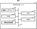
- the cloud server 2 includes a communication interface 20, a CPU (Central Processing Unit) 21, a ROM (Read Only Memory) 22, a RAM (Random Access Memory) 23, and an auxiliary storage device 24. Be prepared. These components are interconnected via a bus 25.
- the communication interface 20 is hardware for communicating with other devices via the network N.
- the CPU 21 controls the cloud server 2 in an integrated manner. Details of the functions of the cloud server 2 realized by the CPU 21 will be described later.
- the ROM 22 stores a plurality of firmwares and data used when executing these firmwares.
- RAM23 is used as a work area for CPU21.
- the auxiliary storage device 24 is composed of a readable and writable nonvolatile semiconductor memory, an HDD (Hard Disk Drive), and the like.
- Examples of the readable and writable nonvolatile semiconductor memory include EEPROM (Electrically Erasable Programmable Read-Only Memory) and flash memory.
- the auxiliary storage device 24 stores a program (hereinafter referred to as a "monitoring program") for monitoring the behavior of a target person who is a resident of house H and notifying information based on the monitoring results to related parties of the target person.
- Various programs included in the memory and data used when executing these programs are stored.
- the related parties include, for example, the subject's relatives, the person in charge of the care support service, the person in charge of the company that manages Building B, and the like.
- the cloud server 2 can acquire the above-mentioned monitoring program or an update program for updating the monitoring program from another server through communication via the network N.
- these programs are compatible with CD-ROMs (Compact Disc Read Only Memory), DVDs (Digital Versatile Discs), magneto-optical discs, USB (Universal Serial Bus) memories, HDDs, SSDs (Solid State Drives), memory cards, etc. It is also possible to store and distribute it on a computer-readable recording medium. When such a recording medium is directly or indirectly attached to the cloud server 2, the cloud server 2 can also read and import the monitoring program or update program from the recording medium.
- the device 3 is an example of a device according to the present disclosure.
- the device 3 is, for example, a home appliance called a so-called IoT (Internet of Things) device, an information home appliance, an internet home appliance, a smart home appliance, etc., and is, for example, an air conditioner, a lighting device, a television, or the like.
- the device 3 is wirelessly connected to a router 4 that is a wireless LAN (Local Area Network) router such as Wi-Fi (registered trademark), and includes hardware for communicating with the cloud server 2 via the router 4. .
- LAN Local Area Network
- the device 3 transmits information regarding its own operation (hereinafter referred to as "device information") to the cloud server 2 at regular intervals (for example, every minute).
- the device information includes identification information that can uniquely identify the device 3, current date and time, information indicating the operating state, measurement results of a sensor (for example, a thermal image sensor such as an infrared thermograph, a temperature sensor, etc.) included in the device 3, etc. is included.
- the identification information of the device 3 is, for example, the serial number, IP address, etc. of the device 3.
- the operating state includes information indicating whether the device is in operation or stopped, and the details of the operation.
- the operation contents include an operation mode indicating cooling, heating, ventilation, dehumidification, etc., and setting contents such as temperature setting, wind speed, and timer setting.
- the operation contents include the output level, etc.
- the operation contents include the channel, the volume, etc.
- the device 3 may be configured to communicate with the cloud server 2 via an external communication adapter (not shown).
- the elevator management device 5 is a computer that manages the operation of the elevator E installed in the building B.
- the elevator management device 5 includes hardware for communicating with the cloud server 2 via the network N.
- the elevator management device 5 transmits information regarding the operation of the elevator E (hereinafter referred to as "elevator information") to the cloud server 2 at regular intervals (for example, every minute).
- the elevator information includes identification information that can uniquely identify elevator E, the current date and time, destination designation information that indicates the destination specified by the user of elevator E, and the operation history of elevator E during the certain period of time. included.
- the user terminal 6 is an example of a terminal device according to the present disclosure.
- the user terminal 6 is an electronic device owned by the above-mentioned person concerned, and is, for example, a smart device such as a smartphone or a tablet terminal.
- the user terminal 6 includes a display 60, an operation reception section 61, a communication interface 62, a CPU 63, a ROM 64, a RAM 65, and an auxiliary storage device 66. These components are interconnected via a bus 67.
- the display 60 is configured to include display devices such as a liquid crystal display and an organic EL (Electro Luminescence) display. Under the control of the CPU 63, the display 60 displays various screens and the like according to the operations of the user (that is, the person related to the subject).
- display devices such as a liquid crystal display and an organic EL (Electro Luminescence) display.
- the display 60 displays various screens and the like according to the operations of the user (that is, the person related to the subject).
- the operation reception unit 61 is configured to include one or more input devices such as push buttons, touch panels, touch pads, etc., receives operation input from the user, and outputs a signal related to the received operation to the CPU 63.
- input devices such as push buttons, touch panels, touch pads, etc.
- the communication interface 62 is hardware for communicating with other devices via the network N.
- the CPU 63 centrally controls the user terminal 6.
- the ROM 64 stores a plurality of firmwares and data used when executing these firmwares.
- the RAM 65 is used as a work area for the CPU 63.
- the auxiliary storage device 66 includes a readable/writable nonvolatile semiconductor memory such as an EEPROM and a flash memory.
- the auxiliary storage device 66 stores various programs including an application program for receiving the monitoring service provided by the monitoring system 1 (hereinafter referred to as "the monitoring application"), and data used when executing these programs. be remembered.
- the user terminal 6 can acquire the monitoring application or an update program for updating the monitoring application from the cloud server 2 or other servers through communication. Furthermore, these programs can also be stored and distributed in computer-readable recording media such as CD-ROMs, DVDs, magneto-optical disks, USB memories, HDDs, SSDs, and memory cards. When such a recording medium is directly or indirectly attached to the user terminal 6, the user terminal 6 may read and acquire the monitoring application or update program from the recording medium.
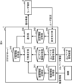
- FIG. 4 is a block diagram showing the functional configuration of the cloud server 2.
- the cloud server 2 includes a setting reception section 200, an equipment information acquisition section 201, an elevator information acquisition section 202, an action estimation section 203, and a notification section 204. These functional units are realized by the CPU 21 executing the above-mentioned monitoring program stored in the auxiliary storage device 24.
- the setting reception unit 200 receives settings for information regarding the monitoring service from users who are related parties.
- the user can set various information via the user terminal 6 using the monitoring application. For example, the user can set the target person's name, address of the target person, identification information of the device 3, notification conditions, etc. via the user terminal 6.
- the identification information of the device 3 can be automatically acquired and set from the device 3 by the user using the monitoring app at the subject's residence H.
- the setting receiving unit 200 stores setting information regarding settings received from the user in the setting information storage unit 240.
- the setting information storage unit 240 is a memory area provided by the auxiliary storage device 24.
- the device information acquisition unit 201 is an example of device information acquisition means according to the present disclosure.
- the device information acquisition unit 201 receives and acquires the above-mentioned device information sent from the device 3 installed in the target person's house H.
- the device information may have a specification that is sent from the device 3 in response to a request from the cloud server 2, or may be a specification that is sent spontaneously from the device 3.
- the device information acquisition unit 201 sorts the acquired device information in chronological order and stores it in the device information storage unit 241. That is, the device information storage section 241 stores the history of device information.
- the device information storage unit 241 is a memory area provided by the auxiliary storage device 24, and is an example of device information storage means according to the present disclosure.
- the elevator information acquisition unit 202 is an example of elevator information acquisition means according to the present disclosure.
- the elevator information acquisition unit 202 receives and acquires the above-mentioned elevator information sent from the elevator management device 5 installed in the building B to which the target person's house H belongs.
- the elevator information may have a specification that is sent from the elevator management device 5 in response to a request from the cloud server 2, or may be a specification that is sent spontaneously from the elevator management device 5.
- the elevator information acquisition unit 202 sorts the acquired elevator information in chronological order and stores it in the elevator information storage unit 242. That is, the history of elevator information is stored in the elevator information storage section 242.
- the elevator information storage unit 242 is a memory area provided by the auxiliary storage device 24, and is an example of elevator information storage means according to the present disclosure.
- the behavior estimation unit 203 is an example of behavior estimation means according to the present disclosure.
- the behavior estimation unit 203 estimates the target person's behavior based on the equipment information stored in the equipment information storage unit 241 and the elevator information stored in the elevator information storage unit 242. Specifically, the behavior estimation unit 203 estimates the target person's behavior based on the history of equipment information and elevator information, and the previous estimation result. In this embodiment, the behavior estimation unit 203 estimates one of going out, coming home, going out, and being at home as the target person's behavior. Each estimation method will be explained below.
- the behavior estimation unit 203 determines that the previous estimation result indicates that the user is at home, and that the operating state of the device 3 changes from the operating state to the stopped state at least a first time and within a second time. If the elevator E arrives at the floor where the subject lives and moves to the first floor, it is assumed that the condition for going out is met and the subject has gone out.
- the first time and the second time mean, for example, the following times. In other words, if it is assumed that the target person's behavior when the operating state of device 3 changes from operating to stopped state is that the target person has left house H or has started preparing to go out, then for the first time, the target person is in house H.
- the second time refers to the shortest time required from leaving the room to using elevator E, and the second time refers to the longest time required from when the subject starts preparing to go out until using elevator E.
- the user can determine the first time and second time based on the subject's daily behavior and set them in the cloud server 2 using the monitoring app.
- the user uses the monitoring app to set the distance from the entrance of house H to the elevator boarding and alighting location on the residential floor, and cloud server 2 determines the first time and second time based on the set distance. You may.
- the cloud server 2 may derive the first time and the second time through learning.
- the behavior estimation unit 203 may determine that the requirement for going out is not met.
- the behavior estimation unit 203 determines that the operating state of the device 3 is in the operating state when the human detection result by the human sensor changes from detected to undetected. Even if the state has not changed from inside to stopped, it may be assumed that the subject has gone out as long as the other conditions described above are met.
- the behavior estimation unit 203 determines that the previous estimation result indicates that the subject is out of the house, and that the operating state of the device 3 changes from the stopped state to the operating state, and that the requirements for returning home are met. It is assumed that the person has returned home. Note that if the operating state of the device 3 changes from the stopped state to the operating state due to the advance timer setting, the behavior estimation unit 203 may determine that the requirements for returning home are not satisfied. In addition, when the device 3 is equipped with a human sensor such as a thermal image sensor, the behavior estimation unit 203 determines whether the previous estimation result indicates that the person is out, and the human detection result by the human sensor changes from undetected to detected. , it is assumed that the subject has returned home, regardless of the operating state of the device 3.
- a human sensor such as a thermal image sensor
- the behavior estimation unit 203 estimates that the subject is going out when the previous estimation result indicates that the subject is going out or going out, and the above-mentioned requirements for returning home are not met.
- the behavior estimation unit 203 estimates that the subject is at home if the previous estimation result indicates that the subject is home or at home, and the above requirements for going out are not met.
- the behavior estimation unit 203 separates the behavior information including the current date and time and the estimation result in chronological order and stores it in the behavior information storage unit 243. That is, the behavior information storage section 243 stores a history of behavior information.
- the behavior information storage unit 243 is a memory area provided by the auxiliary storage device 24.
- the notification unit 204 is an example of notification means according to the present disclosure.
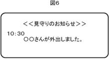
- the notification unit 204 notifies the user, who is a related person, of information regarding the monitoring based on the estimation result by the behavior estimation unit 203. For example, when there is a change in the subject's behavior, the notification unit 204 generates notification information that includes information indicating that the subject has gone out or returned home, and the current time, and transmits it to the user terminal 6.
- the user terminal 6 that has received such notification information displays a user notification screen as shown in FIG. 6 on the display 60, for example, by push notification.
- the notification unit 204 sends notification information that includes information to that effect and the current time. It is generated and transmitted to the user terminal 6.
- the notification unit 204 generates notification information that includes information indicating that the person is at home or out of the house and the current time. , is transmitted to the user terminal 6.
- FIG. 7 shows an example of a user notification screen displayed on the display 60 of the user terminal 6 in this case.
- the user can use the monitoring app to set in advance whether or not to receive notification information at regular intervals.
- the user can also set the time interval for reception in advance using the monitoring app.
- the user can use the monitoring app to set in advance the time period for receiving notification information at regular intervals.
- the notification unit 204 if the user continues to go out beyond a predetermined maximum time for going out, the notification unit 204 generates notification information that includes information to that effect and the current time, and sends the notification information to the user terminal 6.
- FIG. 8 shows an example of a user notification screen displayed on the display 60 of the user terminal 6 in this case. The user can use the monitoring app to set the maximum time for going out in advance.
- the notification unit 204 may generate notification information indicating the current situation of the target person or the history of the target person's actions in response to the user's operation using the monitoring application, and transmit it to the user terminal 6.
- the monitoring application displays a screen based on the notification information.
- FIG. 9 is a flowchart showing the procedure of the monitoring process executed by the cloud server 2.
- the cloud server 2 executes the following monitoring process at regular intervals (for example, every minute).
- Step S100 The cloud server 2 acquires device information from the device 3. After that, the process of the cloud server 2 transitions to step S101.
- Step S101 The cloud server 2 acquires elevator information from the elevator management device 5. After that, the process of the cloud server 2 transitions to step S102.
- Step S102 The cloud server 2 estimates the target person's behavior based on the history of equipment information, the history of elevator information, and the previous estimation result. After that, the process of the cloud server 2 transitions to step S103.
- Step S103 The cloud server 2 determines whether the user needs to be notified. Whether notification is necessary or not is determined based on the presence or absence of a change in behavior and the setting information stored in the setting information storage unit 240. As a result, if notification is required (step S103; YES), the process of the cloud server 2 transitions to step S104. On the other hand, if notification is not required (step S103; NO), the cloud server 2 ends the monitoring process in this cycle.
- Step S104 Cloud server 2 generates notification information. After that, the process of the cloud server 2 transitions to step S105.
- Step S105 The cloud server 2 transmits the generated notification information to the user terminal 6. After that, the cloud server 2 ends the monitoring process in this cycle.
- the user terminal 6 that has received the notification information displays a user notification screen as shown in FIG. 6 on the display 60, for example, by push notification.
- equipment information regarding the operation of the equipment 3 installed in the house H and elevator information regarding the operation of the elevator E installed in the building B to which the house H belongs are stored. Estimate the target person's behavior based on the Therefore, it is possible to improve reliability while respecting privacy in detecting whether or not the subject is out.
- the device 3 is not limited to home appliances, and may be a human sensor that detects a person using infrared rays, visible light, sound waves, sound sense, etc., for example. Further, the router 4 may function as the device 3. That is, the router 4 may transmit device information, which is information regarding its own operation, to the cloud server 2 at regular intervals (for example, every minute).
- a plurality of devices 3 communicably connected to the cloud server 2 may be installed in the target person's residence H. In this case, if there are multiple devices 3 equipped with human sensors, and if a person is detected by any of the human sensors, the behavior estimation unit 203 of the cloud server 2 determines whether the target person is going out or not. Exclude.
- the device 3 may voluntarily transmit the device information to the cloud server 2 using a change in the operating state as a trigger.
- the device 3 equipped with the human sensor spontaneously transmits device information to the cloud server 2 not only when the operating state changes but also when the detection result of the human sensor changes.
- the cloud server 2 may send the notification information to the user terminal 6 by email.
- Modification 5 There may be multiple people involved with one target person. In this case, the cloud server 2 transmits similar notification information to the user terminals 6 of each person involved.
- the setting reception unit 200 of the cloud server 2 can be used only by related parties.
- the notification unit 204 may also receive settings for information regarding the monitoring service from the target person, or the notification unit 204 may send notification information to the terminal device.
- the notification unit 204 may also take into account the device information stored in the device information storage unit 241 to generate the notification information. For example, if the subject goes out without stopping the operation of the device 3, the notification unit 204 generates notification information that includes information to that effect and the current time, and transmits it to the user terminal 6.
- FIG. 10 shows an example of a user notification screen displayed on the display 60 of the user terminal 6 in this case. Further, even though the target person is at home, if the operating state of the device 3 remains in the stopped state after exceeding the predetermined upper limit stop time, the notification unit 204 sends information to that effect and the current time. The notification information containing the information is generated and sent to the user terminal 6.
- FIG. 11 shows an example of a user notification screen displayed on the display 60 of the user terminal 6 in this case.
- the behavior estimation unit 203 may estimate whether the person is going out, coming home, going out, or staying at home, and may also estimate whether the person is preparing to go out. Specifically, the behavior estimation unit 203 calculates the behavior estimation unit 203 when the previous estimation result indicates that the user is at home and the operating state of the device 3 changes from operating to stopped state (or when the human detection result by the human sensor If the detection changes from detection to non-detection), the period from when the elevator E arrives at the floor where the subject resides until the subject moves to the first floor is estimated to be the time when the subject is preparing to go out.
- the behavior estimation unit 203 determines that an abnormality such as poor physical condition has occurred in the target person, and the notification unit 204 determines that an abnormality has occurred while the target person is preparing to go out.
- the user terminal 6 may be notified that there is a possibility that this has occurred.
- the behavior estimation unit 203 may estimate the time immediately before or after returning home. Specifically, if the previous estimation result indicates that the subject is out, and the elevator E moves from the first floor to the floor where the subject resides, the behavior estimation unit 203 determines whether the operating state of the device 3 changes from the stopped state to the next. The period until the change occurs during operation (or until the human detection result by the human sensor changes from undetected to detected) is estimated to be immediately before or after returning home. In addition, the behavior estimation unit 203 determines that an abnormality such as poor physical condition has occurred in the subject if the condition immediately before or after returning home continues for 4 hours or more, and the notification unit 204 determines that the subject has experienced an abnormality such as poor physical condition. Immediately after returning home, the user terminal 6 may be notified that an abnormality may have occurred.
- the user can determine the third and fourth hours based on the subject's daily behavior and set them in the cloud server 2 using the monitoring app.
- the cloud server 2 may be composed of a plurality of separate servers. In this case, for example, there is a device information management server that acquires and manages device information from the device 3, an elevator information management server that acquires and manages elevator information from the elevator management device 5, and a device information management server that acquires and manages the device information from the device information management server.
- the cloud server 2 may be configured by a monitoring server that monitors the target person based on the elevator information acquired from the elevator information management server.
- An identification information acquisition device for acquiring user identification information may be installed in the elevator E or at the boarding/alighting location on each floor of the elevator E.
- the identification information acquisition device is an example of first identification information acquisition means according to the present disclosure.
- the identification information acquisition device is communicably connected to the elevator management device 5 and transmits user information including the acquired user identification information and the current date and time to the elevator management device 5.
- the elevator management device 5 transmits the user information received from the identification information acquisition device to the cloud server 2.
- the setting information stored in the setting information storage unit 240 of the cloud server 2 includes identification information of the target person set in advance by a person concerned. By doing so, the behavior estimation unit 203 of the cloud server 2 can use the user information received from the elevator management device 5 to estimate the behavior of the target person with higher accuracy.
- the cloud server 2 can understand that the subject has entered the elevator E to go home, it is possible to operate the device 3 before the subject returns home. Therefore, it becomes possible to turn on a lighting device or start air conditioning in an air conditioner before the subject returns home, improving the subject's comfort.
- the above-mentioned identification information acquisition device is, for example, a receiver that receives a wireless signal periodically transmitted through BLE (Bluetooth (registered trademark) Low Energy) communication from a mobile terminal such as a mobile phone or a smartphone owned by the target person. It is a device.
- a wireless signal includes identification information (for example, ID (identifier)) of the subject.
- the identification information acquisition device may be an IC tag reader that reads information including identification information (for example, ID) of the target person from an IC tag worn by the target person.
- the identification information acquisition device may be a device that collects a fingerprint of the target person as the target person's identification information, or a CCD (Charge-Coupled Device) that acquires a facial image of the target person as the target person's identification information.
- a visible camera configured with an image sensor such as CMOS (Complementary Metal Oxide Semiconductor).
- a transmitter that periodically transmits a radio signal containing floor number information indicating the floor number may be installed at the boarding/alighting location of each floor of the elevator E.
- the transmitter is an example of a first transmitter according to the present disclosure.
- a mobile terminal such as a mobile phone or a smartphone owned by the subject receives the wireless signal transmitted from the transmitter, acquires the floor information, and obtains the identification information (e.g. ID) of the subject.
- Location information including floor number information and current time is transmitted to the cloud server 2.
- the behavior estimation unit 203 of the cloud server 2 can estimate the target person's behavior with higher accuracy by using the position information received from the target person's mobile terminal.
- the cloud server 2 can understand that the subject has entered the elevator E to go home, it is possible to operate the device 3 before the subject returns home. Therefore, it becomes possible to turn on a lighting device or start air conditioning in an air conditioner before the subject returns home, improving the subject's comfort.
- the identification information acquisition device of Modified Example 10 is installed at the elevator or the boarding and alighting place on each floor of the elevator, and the elevator management device 5 similar to Modified Example 10 is installed. You can also do this.
- the identification information acquisition device is an example of second identification information acquisition means according to the present disclosure. By doing so, if the target person stops by one of the plurality of buildings when going out, the notification unit 204 of the cloud server 2 can notify related parties of the target person's specific location. It becomes possible.
- the cloud server 2 will be able to monitor the target person's outings during that time period. It becomes possible to determine whether or not there is. For example, if the user has not visited the building during the time period, or has visited a different building, the notification unit 204 of the cloud server 2 transmits notification information indicating this to the user terminal 6. Thereby, the person concerned can grasp whether or not the subject has successfully arrived at the destination.
- the transmitter of modification 11 may be installed at the boarding and alighting locations of each elevator floor.
- the transmitter is an example of a second transmitter according to the present disclosure.
- the monitoring system 1 may be applied to watch over a resident (i.e., a target person) of a house equipped with a home elevator.
- a resident i.e., a target person
- the subject's home corresponds to building B
- the home elevator corresponds to elevator E
- each room in the home corresponds to house H.
- the equipment information of the equipment 3 installed in each room and the elevator information it is possible to monitor the entry and exit of the subject from each room.
- the monitoring system 1 may be applied to monitoring employees in an office building.
- the employee is the target person
- the office building is equivalent to Building B
- the elevator in the office building is equivalent to Elevator E
- each room and other predetermined locations in the office building are residential buildings. This corresponds to H.
- the monitoring system 1 of this modification by predetermining the relationship between the equipment 3 installed in each room etc. and the target person, using the equipment information and elevator information of the equipment 3 related to the target person, The behavior of subjects within an office building can be monitored.
- the monitoring system 1 can be applied to watch over one or more subjects such as patients, care recipients, students, etc. in hospitals, nursing care facilities, schools, etc.
- An IC tag reader that reads information from IC tags attached to articles may be installed in the elevator E, and the information read by the IC tag reader may be transmitted to the cloud server 2 via the elevator management device 5. In this way, it becomes possible to monitor whether items in house H have been illegally taken out by a third party other than the subject.
- All or part of the functional units (see FIG. 4) of the cloud server 2 may be realized by dedicated hardware.
- the dedicated hardware is, for example, a single circuit, a composite circuit, a programmed processor, an ASIC (Application Specific Integrated Circuit), an FPGA (Field-Programmable Gate Array), or a combination thereof.
- Embodiment 2 Next, a second embodiment of the present disclosure will be described. Note that in the following description, the same components and the like as those in Embodiment 1 are given the same reference numerals, and the description thereof will be omitted.
- FIG. 12 is a diagram showing the overall configuration of a monitoring system 1A in Embodiment 2 of the present disclosure.
- the monitoring system 1A is an example of a monitoring system according to the present disclosure, and it monitors the residents of a house H (hereinafter referred to as "target persons"), which is an example of a person to be monitored according to the present disclosure, and also monitors the use of elevators by the target persons.
- target persons which is an example of a person to be monitored according to the present disclosure
- the monitoring system 1A includes a cloud server 2A, a device 3 and a router 4 installed in a house H, an elevator management device 5A installed in a building B such as an apartment to which the house H belongs, and a user terminal 6. Note that the house H is located on the second or higher floor of the building B.
- the cloud server 2A is an example of a server according to the present disclosure.
- the cloud server 2A is a server computer installed and operated by the manufacturer, sales company, etc. of the equipment 3 and the elevator E installed in the building B, and is connected to the network N, which is a wide area network such as the Internet.
- the hardware configuration of cloud server 2A is similar to cloud server 2 of Embodiment 1 (see FIG. 2). Details of the functions of the cloud server 2A will be described later.
- the elevator management device 5A is an example of elevator management means according to the present disclosure.
- the elevator management device 5A is a computer that manages the operation of the elevator E installed in the building B.
- the elevator management device 5A includes hardware for communicating with the cloud server 2A via the network N, and periodically (for example, every minute), the elevator management device 5A Elevator information, which is information regarding the operation of the elevator, is transmitted to the cloud server 2A.
- the elevator management device 5A also controls the movement of the elevator E to the floor where the target person resides in accordance with a command from the cloud server 2A.
- FIG. 13 is a block diagram showing the functional configuration of the cloud server 2A.
- the cloud server 2A includes a setting reception section 200, a device information acquisition section 201, an elevator information acquisition section 202, an action estimation section 203, a notification section 204, and a call command section 205.
- These functional units are realized by the CPU 21 of the cloud server 2A executing the monitoring program and elevator usage support program stored in the auxiliary storage device 24.
- the monitoring program is a program to monitor the behavior of the target person who is a resident of House H, and to notify the relevant person of the target person of information based on the monitoring results. This is a program to support the use of elevator E.
- the functions of the setting reception unit 200, device information acquisition unit 201, elevator information acquisition unit 202, behavior estimation unit 203, and notification unit 204 are the same as those in the cloud server 2 of the first embodiment.
- the call command unit 205 is an example of a call command means according to the present disclosure.
- the call command unit 205 instructs the elevator management device 5A to call the elevator E when it is necessary to call the elevator E to the floor where the subject resides.
- the call command unit 205 sends a message to the target person's residence floor based on the latest equipment information stored in the equipment information storage unit 241 and the setting information stored in the setting information storage unit 240. Determine whether it is necessary to call elevator E.
- the call command unit 205 calls the elevator E to the floor where the target person resides. It is determined that this is necessary.
- the scheduled elevator use time period is a time period in which the subject is likely to use the elevator E, and is set in advance by a user who is a related party via a monitoring application.
- the call command unit 205 changes the operating state of the device 3 from in operation to when the detection result by the human sensor changes from detected to undetected. Even if the state has not changed to the stopped state, it may be determined that it is necessary to call the elevator E to the floor where the subject resides if the elevator is scheduled to be used.
- the call command unit 205 When the call command unit 205 determines that it is necessary to call the elevator E to the target person's residence floor, the call command unit 205 generates call command information and transmits it to the elevator management device 5A.
- the call command information includes information indicating the call floor (that is, the target person's residence floor) and the scheduled time of use.
- the scheduled usage time is the time when the target person is scheduled to arrive at the elevator boarding and alighting location on the called floor.
- the scheduled usage time is determined by adding the time required for the target person to move (hereinafter referred to as "required travel time") to the current time.
- the user can determine the travel time required from the subject's daily behavior and set it in the cloud server 2A using the monitoring app.
- the user may use the monitoring app to set the distance from the entrance of house H to the elevator boarding and alighting location on the residential floor, and the cloud server 2A may determine the travel time based on the set distance.
- the cloud server 2A may derive the required travel time through learning.
- the elevator management device 5A controls the operation of the elevator E so that the elevator E arrives at the called floor by the scheduled time of use.
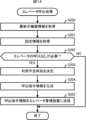
- FIG. 14 is a flowchart showing the procedure of elevator calling processing executed by the cloud server 2A.
- the cloud server 2A executes the following elevator calling process at regular intervals (for example, every minute) in parallel with the above-mentioned monitoring process.
- Step S200 The cloud server 2A acquires the latest device information from the device information storage section 241. After that, the process of the cloud server 2A transitions to step S201.
- Step S201 The cloud server 2A reads and acquires the setting information from the setting information storage unit 240. After that, the process of the cloud server 2A transitions to step S202.
- Step S202 The cloud server 2A determines whether or not it is necessary to call the elevator E to the target person's residence floor based on the latest equipment information and the scheduled elevator use time period included in the setting information. As a result, if it is necessary to call the elevator E to the target person's residence floor (step S202; YES), the process of the cloud server 2A transitions to step S203. On the other hand, if it is not necessary to call the elevator E to the target person's residence floor (step S202; NO), the cloud server 2A ends the elevator calling process in this cycle.
- Step S203 The cloud server 2A determines the scheduled usage time based on the current time and the required travel time. After that, the process of the cloud server 2A transitions to step S204.
- Step S204 The cloud server 2A generates call command information that includes information indicating a call floor and a scheduled time of use. After that, the process of the cloud server 2A transitions to step S205.
- Step S205 The cloud server 2A transmits the generated call command information to the elevator management device 5A. After that, the cloud server 2A ends the elevator calling process in this cycle.
- the elevator management device 5A that has received the call command information controls the operation of the elevator E so that the elevator E arrives at the floor where the target person resides by the scheduled time of use by the target person.
- equipment information regarding the operation of the equipment 3 installed in the house H and elevator information regarding the operation of the elevator E installed in the building B to which the house H belongs are stored. Estimate the target person's behavior based on the Therefore, it is possible to improve reliability while respecting privacy in detecting whether or not the subject is out.
- the elevator E can be automatically moved to the floor where the subject resides when the subject goes out, the convenience of the subject when going out is significantly improved.
- Modification 1 When the configuration of the modification 12 of the first embodiment is added to the monitoring system 1A, and the behavior estimation unit 203 estimates that the target person stopped at one of the plurality of buildings when going out, a call command is issued.
- the department 205 may call the elevator E to the first floor.
- the call command unit 205 determines the time required for returning home, which is preset corresponding to the building, after the behavior estimation unit 203 estimates that the target person has stopped at one of the plurality of buildings. Once the time has elapsed, the elevator E may be called to the first floor. The user can use the monitoring app to set the required return time corresponding to each building in the cloud server 2A. In this way, when a subject who has stopped by one of the above-mentioned buildings arrives at building B on his way home, there is a high possibility that he will be able to use elevator E immediately. The convenience of the service will be significantly improved.
- Modification 2 When the configuration of Modified Example 13 of Embodiment 1 is added to the monitoring system 1A, and the behavior estimation unit 203 estimates that the target person stopped by one of the plurality of buildings when going out, a call command is issued.
- the department 205 may call the elevator E to the first floor.
- the call command unit 205 after the behavior estimation unit 203 estimates that the target person has stopped by one of the plurality of buildings, responds to the building in response to the said building.
- the elevator E When a preset time required for returning home has elapsed, the elevator E may be called to the first floor.
- All or part of the functional units (see FIG. 13) of the cloud server 2A may be realized by dedicated hardware.
- Dedicated hardware can be, for example, a single circuit, a complex circuit, a programmed processor, an ASIC, an FPGA, or a combination thereof.
- Modification 4 Modifications 1 to 15 of Embodiment 1 can also be applied to this embodiment.
- the present disclosure can be suitably employed in technology for watching over elderly people, disabled people, etc.
Landscapes
- Business, Economics & Management (AREA)
- Health & Medical Sciences (AREA)
- General Physics & Mathematics (AREA)
- General Health & Medical Sciences (AREA)
- Tourism & Hospitality (AREA)
- Physics & Mathematics (AREA)
- Emergency Management (AREA)
- Child & Adolescent Psychology (AREA)
- Gerontology & Geriatric Medicine (AREA)
- Economics (AREA)
- Human Resources & Organizations (AREA)
- Marketing (AREA)
- Primary Health Care (AREA)
- Strategic Management (AREA)
- General Business, Economics & Management (AREA)
- Engineering & Computer Science (AREA)
- Theoretical Computer Science (AREA)
- Alarm Systems (AREA)
Priority Applications (2)
| Application Number | Priority Date | Filing Date | Title |
|---|---|---|---|
| JP2024507350A JP7760041B2 (ja) | 2022-03-17 | 2022-03-17 | 監視システム、サーバ及び監視方法 |
| PCT/JP2022/012316 WO2023175839A1 (ja) | 2022-03-17 | 2022-03-17 | 監視システム、サーバ及び監視方法 |
Applications Claiming Priority (1)
| Application Number | Priority Date | Filing Date | Title |
|---|---|---|---|
| PCT/JP2022/012316 WO2023175839A1 (ja) | 2022-03-17 | 2022-03-17 | 監視システム、サーバ及び監視方法 |
Publications (1)
| Publication Number | Publication Date |
|---|---|
| WO2023175839A1 true WO2023175839A1 (ja) | 2023-09-21 |
Family
ID=88022557
Family Applications (1)
| Application Number | Title | Priority Date | Filing Date |
|---|---|---|---|
| PCT/JP2022/012316 Ceased WO2023175839A1 (ja) | 2022-03-17 | 2022-03-17 | 監視システム、サーバ及び監視方法 |
Country Status (2)
| Country | Link |
|---|---|
| JP (1) | JP7760041B2 (https=) |
| WO (1) | WO2023175839A1 (https=) |
Cited By (2)
| Publication number | Priority date | Publication date | Assignee | Title |
|---|---|---|---|---|
| CN117423066A (zh) * | 2023-12-15 | 2024-01-19 | 四川三思德科技有限公司 | 一种基于多源数据融合分析的目标人员识别方法 |
| JP7562780B1 (ja) | 2023-07-21 | 2024-10-07 | 東芝エレベータ株式会社 | 見守りシステム |
Citations (5)
| Publication number | Priority date | Publication date | Assignee | Title |
|---|---|---|---|---|
| JP2003178378A (ja) * | 2001-12-12 | 2003-06-27 | Sekisui Chem Co Ltd | 生活見守りシステム |
| JP2006107187A (ja) * | 2004-10-06 | 2006-04-20 | Mitsubishi Electric Building Techno Service Co Ltd | 顔画像認証による情報配信システム |
| JP2014086929A (ja) * | 2012-10-25 | 2014-05-12 | Japan Delivery System Corp | 集合住宅の居住者支援システム |
| JP2014222498A (ja) * | 2013-05-13 | 2014-11-27 | エルエス産電株式会社Lsis Co., Ltd. | 独居老人ケアシステム |
| JP2017039574A (ja) * | 2015-08-19 | 2017-02-23 | 東芝エレベータ株式会社 | エレベータ利用情報提供システム |
-
2022
- 2022-03-17 JP JP2024507350A patent/JP7760041B2/ja active Active
- 2022-03-17 WO PCT/JP2022/012316 patent/WO2023175839A1/ja not_active Ceased
Patent Citations (5)
| Publication number | Priority date | Publication date | Assignee | Title |
|---|---|---|---|---|
| JP2003178378A (ja) * | 2001-12-12 | 2003-06-27 | Sekisui Chem Co Ltd | 生活見守りシステム |
| JP2006107187A (ja) * | 2004-10-06 | 2006-04-20 | Mitsubishi Electric Building Techno Service Co Ltd | 顔画像認証による情報配信システム |
| JP2014086929A (ja) * | 2012-10-25 | 2014-05-12 | Japan Delivery System Corp | 集合住宅の居住者支援システム |
| JP2014222498A (ja) * | 2013-05-13 | 2014-11-27 | エルエス産電株式会社Lsis Co., Ltd. | 独居老人ケアシステム |
| JP2017039574A (ja) * | 2015-08-19 | 2017-02-23 | 東芝エレベータ株式会社 | エレベータ利用情報提供システム |
Cited By (4)
| Publication number | Priority date | Publication date | Assignee | Title |
|---|---|---|---|---|
| JP7562780B1 (ja) | 2023-07-21 | 2024-10-07 | 東芝エレベータ株式会社 | 見守りシステム |
| JP2025016019A (ja) * | 2023-07-21 | 2025-01-31 | 東芝エレベータ株式会社 | 見守りシステム |
| CN117423066A (zh) * | 2023-12-15 | 2024-01-19 | 四川三思德科技有限公司 | 一种基于多源数据融合分析的目标人员识别方法 |
| CN117423066B (zh) * | 2023-12-15 | 2024-02-27 | 四川三思德科技有限公司 | 一种基于多源数据融合分析的目标人员识别方法 |
Also Published As
| Publication number | Publication date |
|---|---|
| JP7760041B2 (ja) | 2025-10-24 |
| JPWO2023175839A1 (https=) | 2023-09-21 |
Similar Documents
| Publication | Publication Date | Title |
|---|---|---|
| US10446007B2 (en) | Watching system and management server | |
| JP6589125B2 (ja) | 感染拡大防止システム、感染拡大防止システムの制御方法、およびそのプログラム | |
| JP6680336B2 (ja) | 被監視者監視システム、端末ユニットおよびコンピュータプログラム | |
| JP6988798B2 (ja) | 見守りシステム | |
| JP5898765B2 (ja) | 省電力制御システム、機器制御装置、および、省電力制御方法 | |
| JP6445815B2 (ja) | 情報処理装置、プログラム及び情報処理方法 | |
| WO2022192650A1 (en) | Connected contact tracing | |
| US12323742B2 (en) | Access control system | |
| JP7760041B2 (ja) | 監視システム、サーバ及び監視方法 | |
| CN110228738B (zh) | 灾害信息处理装置以及灾害信息通知方法 | |
| WO2019216045A1 (ja) | システム、およびシステムの制御方法 | |
| WO2020003758A1 (ja) | レポート出力プログラム、レポート出力方法、およびレポート出力装置 | |
| JP2025163224A (ja) | 警備システム、携帯端末、プログラム及び警備方法 | |
| JP2019114107A (ja) | 浴室見守り装置及び方法、外部機器並びにプログラム | |
| JP2020126553A (ja) | 見守りシステム、および見守りシステムの制御プログラム | |
| JP2013186554A (ja) | 救助活動支援システム | |
| JP2015158782A (ja) | 不審者追跡支援システム、設備機器コントローラ及びプログラム | |
| JP7764692B2 (ja) | 情報処理装置、情報処理システム、解析結果提供方法、および制御プログラム | |
| JP6213699B1 (ja) | 被監視者監視システムの中央処理装置および中央処理方法ならびに被監視者監視システム | |
| KR101329257B1 (ko) | 공동주택 거주자의 안전관리장치 및 안전관리방법 | |
| US20250260791A1 (en) | Non-transitory computer-readable recording medium, watching system, and control device | |
| WO2016159067A1 (ja) | 活動量算出システム、活動量算出装置、活動量算出方法、およびコンピュータ読み取り可能な記録媒体 | |
| US20260025485A1 (en) | Non-transitory computer-readable recording medium, watching system, and control device | |
| JP2021015499A (ja) | 制御装置、制御プログラム、および制御方法 | |
| JP2021015497A (ja) | 制御装置、制御プログラム、および制御方法 |
Legal Events
| Date | Code | Title | Description |
|---|---|---|---|
| 121 | Ep: the epo has been informed by wipo that ep was designated in this application |
Ref document number: 22932113 Country of ref document: EP Kind code of ref document: A1 |
|
| ENP | Entry into the national phase |
Ref document number: 2024507350 Country of ref document: JP Kind code of ref document: A |
|
| NENP | Non-entry into the national phase |
Ref country code: DE |
|
| 122 | Ep: pct application non-entry in european phase |
Ref document number: 22932113 Country of ref document: EP Kind code of ref document: A1 |