WO2023175839A1 - 監視システム、サーバ及び監視方法 - Google Patents
監視システム、サーバ及び監視方法 Download PDFInfo
- Publication number
- WO2023175839A1 WO2023175839A1 PCT/JP2022/012316 JP2022012316W WO2023175839A1 WO 2023175839 A1 WO2023175839 A1 WO 2023175839A1 JP 2022012316 W JP2022012316 W JP 2022012316W WO 2023175839 A1 WO2023175839 A1 WO 2023175839A1
- Authority
- WO
- WIPO (PCT)
- Prior art keywords
- elevator
- information
- person
- behavior
- watched
- Prior art date
Links
- 238000012544 monitoring process Methods 0.000 title claims abstract description 83
- 238000000034 method Methods 0.000 title claims description 23
- 238000001514 detection method Methods 0.000 claims description 10
- 230000009471 action Effects 0.000 abstract description 5
- 230000006399 behavior Effects 0.000 description 63
- 230000004048 modification Effects 0.000 description 33
- 238000012986 modification Methods 0.000 description 33
- 238000010586 diagram Methods 0.000 description 16
- 230000015654 memory Effects 0.000 description 14
- 230000008569 process Effects 0.000 description 13
- 230000007704 transition Effects 0.000 description 10
- 238000004891 communication Methods 0.000 description 9
- 230000005856 abnormality Effects 0.000 description 5
- 230000008859 change Effects 0.000 description 5
- 230000006870 function Effects 0.000 description 5
- 238000012545 processing Methods 0.000 description 5
- 230000000694 effects Effects 0.000 description 4
- 230000004044 response Effects 0.000 description 4
- 239000004065 semiconductor Substances 0.000 description 4
- 238000004378 air conditioning Methods 0.000 description 2
- 238000012790 confirmation Methods 0.000 description 2
- 238000005401 electroluminescence Methods 0.000 description 2
- 238000005516 engineering process Methods 0.000 description 2
- 230000000295 complement effect Effects 0.000 description 1
- 239000002131 composite material Substances 0.000 description 1
- 238000001816 cooling Methods 0.000 description 1
- 238000007791 dehumidification Methods 0.000 description 1
- 230000001815 facial effect Effects 0.000 description 1
- 238000010438 heat treatment Methods 0.000 description 1
- 230000008676 import Effects 0.000 description 1
- 239000004973 liquid crystal related substance Substances 0.000 description 1
- 238000005259 measurement Methods 0.000 description 1
- 229910044991 metal oxide Inorganic materials 0.000 description 1
- 150000004706 metal oxides Chemical class 0.000 description 1
- 230000000474 nursing effect Effects 0.000 description 1
- 239000007787 solid Substances 0.000 description 1
- 238000009423 ventilation Methods 0.000 description 1
Images


Classifications
-
- G—PHYSICS
- G06—COMPUTING; CALCULATING OR COUNTING
- G06Q—INFORMATION AND COMMUNICATION TECHNOLOGY [ICT] SPECIALLY ADAPTED FOR ADMINISTRATIVE, COMMERCIAL, FINANCIAL, MANAGERIAL OR SUPERVISORY PURPOSES; SYSTEMS OR METHODS SPECIALLY ADAPTED FOR ADMINISTRATIVE, COMMERCIAL, FINANCIAL, MANAGERIAL OR SUPERVISORY PURPOSES, NOT OTHERWISE PROVIDED FOR
- G06Q50/00—Information and communication technology [ICT] specially adapted for implementation of business processes of specific business sectors, e.g. utilities or tourism
- G06Q50/10—Services
- G06Q50/22—Social work or social welfare, e.g. community support activities or counselling services
-
- G—PHYSICS
- G08—SIGNALLING
- G08B—SIGNALLING OR CALLING SYSTEMS; ORDER TELEGRAPHS; ALARM SYSTEMS
- G08B21/00—Alarms responsive to a single specified undesired or abnormal condition and not otherwise provided for
- G08B21/02—Alarms for ensuring the safety of persons
- G08B21/04—Alarms for ensuring the safety of persons responsive to non-activity, e.g. of elderly persons
Definitions
- the present disclosure relates to a monitoring system, a server, and a monitoring method.
- Patent Document 1 discloses that, in order to avoid the person being monitored, the behavior of the person being watched is understood by turning on/off a lighting device installed in the person's home. The safety confirmation system is described.
- the cloud server In this safety confirmation system, the cloud server generates safety information according to safety notification rules set and registered in advance by referring to the history of turning on/off lighting devices in the home of the person being watched. Then, the cloud server sends the generated safety information to an external terminal owned by a guardian such as a separated family member or a care manager of the subject.
- a guardian such as a separated family member or a care manager of the subject.
- the person being watched always carries a mobile device equipped with a GPS (Global Positioning System) function, such as a mobile phone or smartphone, the current location of the person being watched can be grasped. It is possible to check whether the user is going out or not.
- GPS Global Positioning System
- the person being watched does not necessarily carry the mobile terminal with him or her, and the basis for determining whether or not he/she is going out is unreliable.
- the reality is that there is a need to propose a new technology to improve reliability while respecting privacy when it comes to detecting whether a person under surveillance is out or not.
- the present disclosure has been made in view of the above circumstances, and provides a monitoring system, server, and monitoring method that can improve reliability while respecting privacy in detecting whether or not a person to be monitored is out.
- the purpose is to
- the monitoring system in order to achieve the above purpose, the monitoring system according to the present disclosure: equipment information acquisition means for acquiring equipment information regarding the operation of equipment installed in the residence; Elevator information acquisition means for acquiring elevator information regarding the operation of an elevator installed in a building to which the residence belongs; equipment information storage means for storing the equipment information; elevator information storage means for storing the elevator information; The apparatus further comprises a behavior estimation means for estimating the behavior of the person to be watched based on the equipment information stored in the equipment information storage means and the elevator information stored in the elevator information storage means.
- the behavior of the person being watched is estimated based on device information regarding the operation of devices installed in the house and elevator information regarding the operation of the elevator installed in the building to which the house belongs. This makes it possible to improve reliability while respecting privacy in detecting whether a person is out or not.
- a diagram showing the overall configuration of a monitoring system in Embodiment 1 Block diagram showing the hardware configuration of a cloud server in Embodiment 1 Block diagram showing the hardware configuration of a user terminal in Embodiment 1 Block diagram showing the functional configuration of the cloud server in Embodiment 1 A diagram showing the relationship between estimated target person behavior and requirements in Embodiment 1
- a diagram showing an example of a user notification screen in Embodiment 1 A diagram showing an example of a user notification screen in Embodiment 1
- a diagram showing an example of a user notification screen in Embodiment 1 A diagram showing an example of a user notification screen in Embodiment 1
- Flowchart showing the procedure of monitoring processing in Embodiment 1 A diagram showing an example of a user notification screen in a modification of the first embodiment
- Diagram showing the overall configuration of a monitoring system in Embodiment 2 Block diagram showing the functional configuration of a cloud server in Embodiment 2 Flowchart showing
- FIG. 1 is a diagram showing the overall configuration of a monitoring system 1 according to Embodiment 1 of the present disclosure.
- the monitoring system 1 is an example of a monitoring system according to the present disclosure, and is a system for monitoring a resident of a house H (hereinafter referred to as a "target person"), which is an example of a person to be watched over according to the present disclosure.
- the monitoring system 1 includes a cloud server 2, a device 3 and a router 4 installed in a house H, an elevator management device 5 installed in a building B such as an apartment to which the house H belongs, and a user terminal 6. Note that the house H is located on the second or higher floor of the building B.
- the cloud server 2 is an example of a server according to the present disclosure.
- the cloud server 2 is a server computer installed and operated by the manufacturer, sales company, etc. of the equipment 3 and the elevator E installed in the building B, and is connected to the network N, which is a wide area network such as the Internet.
- the cloud server 2 includes a communication interface 20, a CPU (Central Processing Unit) 21, a ROM (Read Only Memory) 22, a RAM (Random Access Memory) 23, and an auxiliary storage device 24. Be prepared. These components are interconnected via a bus 25.
- the communication interface 20 is hardware for communicating with other devices via the network N.
- the CPU 21 controls the cloud server 2 in an integrated manner. Details of the functions of the cloud server 2 realized by the CPU 21 will be described later.
- the ROM 22 stores a plurality of firmwares and data used when executing these firmwares.
- RAM23 is used as a work area for CPU21.
- the auxiliary storage device 24 is composed of a readable and writable nonvolatile semiconductor memory, an HDD (Hard Disk Drive), and the like.
- Examples of the readable and writable nonvolatile semiconductor memory include EEPROM (Electrically Erasable Programmable Read-Only Memory) and flash memory.
- the auxiliary storage device 24 stores a program (hereinafter referred to as a "monitoring program") for monitoring the behavior of a target person who is a resident of house H and notifying information based on the monitoring results to related parties of the target person.
- Various programs included in the memory and data used when executing these programs are stored.
- the related parties include, for example, the subject's relatives, the person in charge of the care support service, the person in charge of the company that manages Building B, and the like.
- the cloud server 2 can acquire the above-mentioned monitoring program or an update program for updating the monitoring program from another server through communication via the network N.
- these programs are compatible with CD-ROMs (Compact Disc Read Only Memory), DVDs (Digital Versatile Discs), magneto-optical discs, USB (Universal Serial Bus) memories, HDDs, SSDs (Solid State Drives), memory cards, etc. It is also possible to store and distribute it on a computer-readable recording medium. When such a recording medium is directly or indirectly attached to the cloud server 2, the cloud server 2 can also read and import the monitoring program or update program from the recording medium.
- the device 3 is an example of a device according to the present disclosure.
- the device 3 is, for example, a home appliance called a so-called IoT (Internet of Things) device, an information home appliance, an internet home appliance, a smart home appliance, etc., and is, for example, an air conditioner, a lighting device, a television, or the like.
- the device 3 is wirelessly connected to a router 4 that is a wireless LAN (Local Area Network) router such as Wi-Fi (registered trademark), and includes hardware for communicating with the cloud server 2 via the router 4. .
- LAN Local Area Network
- the device 3 transmits information regarding its own operation (hereinafter referred to as "device information") to the cloud server 2 at regular intervals (for example, every minute).
- the device information includes identification information that can uniquely identify the device 3, current date and time, information indicating the operating state, measurement results of a sensor (for example, a thermal image sensor such as an infrared thermograph, a temperature sensor, etc.) included in the device 3, etc. is included.
- the identification information of the device 3 is, for example, the serial number, IP address, etc. of the device 3.
- the operating state includes information indicating whether the device is in operation or stopped, and the details of the operation.
- the operation contents include an operation mode indicating cooling, heating, ventilation, dehumidification, etc., and setting contents such as temperature setting, wind speed, and timer setting.
- the operation contents include the output level, etc.
- the operation contents include the channel, the volume, etc.
- the device 3 may be configured to communicate with the cloud server 2 via an external communication adapter (not shown).
- the elevator management device 5 is a computer that manages the operation of the elevator E installed in the building B.
- the elevator management device 5 includes hardware for communicating with the cloud server 2 via the network N.
- the elevator management device 5 transmits information regarding the operation of the elevator E (hereinafter referred to as "elevator information") to the cloud server 2 at regular intervals (for example, every minute).
- the elevator information includes identification information that can uniquely identify elevator E, the current date and time, destination designation information that indicates the destination specified by the user of elevator E, and the operation history of elevator E during the certain period of time. included.
- the user terminal 6 is an example of a terminal device according to the present disclosure.
- the user terminal 6 is an electronic device owned by the above-mentioned person concerned, and is, for example, a smart device such as a smartphone or a tablet terminal.
- the user terminal 6 includes a display 60, an operation reception section 61, a communication interface 62, a CPU 63, a ROM 64, a RAM 65, and an auxiliary storage device 66. These components are interconnected via a bus 67.
- the display 60 is configured to include display devices such as a liquid crystal display and an organic EL (Electro Luminescence) display. Under the control of the CPU 63, the display 60 displays various screens and the like according to the operations of the user (that is, the person related to the subject).
- display devices such as a liquid crystal display and an organic EL (Electro Luminescence) display.
- the display 60 displays various screens and the like according to the operations of the user (that is, the person related to the subject).
- the operation reception unit 61 is configured to include one or more input devices such as push buttons, touch panels, touch pads, etc., receives operation input from the user, and outputs a signal related to the received operation to the CPU 63.
- input devices such as push buttons, touch panels, touch pads, etc.
- the communication interface 62 is hardware for communicating with other devices via the network N.
- the CPU 63 centrally controls the user terminal 6.
- the ROM 64 stores a plurality of firmwares and data used when executing these firmwares.
- the RAM 65 is used as a work area for the CPU 63.
- the auxiliary storage device 66 includes a readable/writable nonvolatile semiconductor memory such as an EEPROM and a flash memory.
- the auxiliary storage device 66 stores various programs including an application program for receiving the monitoring service provided by the monitoring system 1 (hereinafter referred to as "the monitoring application"), and data used when executing these programs. be remembered.
- the user terminal 6 can acquire the monitoring application or an update program for updating the monitoring application from the cloud server 2 or other servers through communication. Furthermore, these programs can also be stored and distributed in computer-readable recording media such as CD-ROMs, DVDs, magneto-optical disks, USB memories, HDDs, SSDs, and memory cards. When such a recording medium is directly or indirectly attached to the user terminal 6, the user terminal 6 may read and acquire the monitoring application or update program from the recording medium.
- FIG. 4 is a block diagram showing the functional configuration of the cloud server 2.
- the cloud server 2 includes a setting reception section 200, an equipment information acquisition section 201, an elevator information acquisition section 202, an action estimation section 203, and a notification section 204. These functional units are realized by the CPU 21 executing the above-mentioned monitoring program stored in the auxiliary storage device 24.
- the setting reception unit 200 receives settings for information regarding the monitoring service from users who are related parties.
- the user can set various information via the user terminal 6 using the monitoring application. For example, the user can set the target person's name, address of the target person, identification information of the device 3, notification conditions, etc. via the user terminal 6.
- the identification information of the device 3 can be automatically acquired and set from the device 3 by the user using the monitoring app at the subject's residence H.
- the setting receiving unit 200 stores setting information regarding settings received from the user in the setting information storage unit 240.
- the setting information storage unit 240 is a memory area provided by the auxiliary storage device 24.
- the device information acquisition unit 201 is an example of device information acquisition means according to the present disclosure.
- the device information acquisition unit 201 receives and acquires the above-mentioned device information sent from the device 3 installed in the target person's house H.
- the device information may have a specification that is sent from the device 3 in response to a request from the cloud server 2, or may be a specification that is sent spontaneously from the device 3.
- the device information acquisition unit 201 sorts the acquired device information in chronological order and stores it in the device information storage unit 241. That is, the device information storage section 241 stores the history of device information.
- the device information storage unit 241 is a memory area provided by the auxiliary storage device 24, and is an example of device information storage means according to the present disclosure.
- the elevator information acquisition unit 202 is an example of elevator information acquisition means according to the present disclosure.
- the elevator information acquisition unit 202 receives and acquires the above-mentioned elevator information sent from the elevator management device 5 installed in the building B to which the target person's house H belongs.
- the elevator information may have a specification that is sent from the elevator management device 5 in response to a request from the cloud server 2, or may be a specification that is sent spontaneously from the elevator management device 5.
- the elevator information acquisition unit 202 sorts the acquired elevator information in chronological order and stores it in the elevator information storage unit 242. That is, the history of elevator information is stored in the elevator information storage section 242.
- the elevator information storage unit 242 is a memory area provided by the auxiliary storage device 24, and is an example of elevator information storage means according to the present disclosure.
- the behavior estimation unit 203 is an example of behavior estimation means according to the present disclosure.
- the behavior estimation unit 203 estimates the target person's behavior based on the equipment information stored in the equipment information storage unit 241 and the elevator information stored in the elevator information storage unit 242. Specifically, the behavior estimation unit 203 estimates the target person's behavior based on the history of equipment information and elevator information, and the previous estimation result. In this embodiment, the behavior estimation unit 203 estimates one of going out, coming home, going out, and being at home as the target person's behavior. Each estimation method will be explained below.
- the behavior estimation unit 203 determines that the previous estimation result indicates that the user is at home, and that the operating state of the device 3 changes from the operating state to the stopped state at least a first time and within a second time. If the elevator E arrives at the floor where the subject lives and moves to the first floor, it is assumed that the condition for going out is met and the subject has gone out.
- the first time and the second time mean, for example, the following times. In other words, if it is assumed that the target person's behavior when the operating state of device 3 changes from operating to stopped state is that the target person has left house H or has started preparing to go out, then for the first time, the target person is in house H.
- the second time refers to the shortest time required from leaving the room to using elevator E, and the second time refers to the longest time required from when the subject starts preparing to go out until using elevator E.
- the user can determine the first time and second time based on the subject's daily behavior and set them in the cloud server 2 using the monitoring app.
- the user uses the monitoring app to set the distance from the entrance of house H to the elevator boarding and alighting location on the residential floor, and cloud server 2 determines the first time and second time based on the set distance. You may.
- the cloud server 2 may derive the first time and the second time through learning.
- the behavior estimation unit 203 may determine that the requirement for going out is not met.
- the behavior estimation unit 203 determines that the operating state of the device 3 is in the operating state when the human detection result by the human sensor changes from detected to undetected. Even if the state has not changed from inside to stopped, it may be assumed that the subject has gone out as long as the other conditions described above are met.
- the behavior estimation unit 203 determines that the previous estimation result indicates that the subject is out of the house, and that the operating state of the device 3 changes from the stopped state to the operating state, and that the requirements for returning home are met. It is assumed that the person has returned home. Note that if the operating state of the device 3 changes from the stopped state to the operating state due to the advance timer setting, the behavior estimation unit 203 may determine that the requirements for returning home are not satisfied. In addition, when the device 3 is equipped with a human sensor such as a thermal image sensor, the behavior estimation unit 203 determines whether the previous estimation result indicates that the person is out, and the human detection result by the human sensor changes from undetected to detected. , it is assumed that the subject has returned home, regardless of the operating state of the device 3.
- a human sensor such as a thermal image sensor
- the behavior estimation unit 203 estimates that the subject is going out when the previous estimation result indicates that the subject is going out or going out, and the above-mentioned requirements for returning home are not met.
- the behavior estimation unit 203 estimates that the subject is at home if the previous estimation result indicates that the subject is home or at home, and the above requirements for going out are not met.
- the behavior estimation unit 203 separates the behavior information including the current date and time and the estimation result in chronological order and stores it in the behavior information storage unit 243. That is, the behavior information storage section 243 stores a history of behavior information.
- the behavior information storage unit 243 is a memory area provided by the auxiliary storage device 24.
- the notification unit 204 is an example of notification means according to the present disclosure.
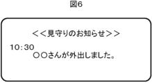
- the notification unit 204 notifies the user, who is a related person, of information regarding the monitoring based on the estimation result by the behavior estimation unit 203. For example, when there is a change in the subject's behavior, the notification unit 204 generates notification information that includes information indicating that the subject has gone out or returned home, and the current time, and transmits it to the user terminal 6.
- the user terminal 6 that has received such notification information displays a user notification screen as shown in FIG. 6 on the display 60, for example, by push notification.
- the notification unit 204 sends notification information that includes information to that effect and the current time. It is generated and transmitted to the user terminal 6.
- the notification unit 204 generates notification information that includes information indicating that the person is at home or out of the house and the current time. , is transmitted to the user terminal 6.
- FIG. 7 shows an example of a user notification screen displayed on the display 60 of the user terminal 6 in this case.
- the user can use the monitoring app to set in advance whether or not to receive notification information at regular intervals.
- the user can also set the time interval for reception in advance using the monitoring app.
- the user can use the monitoring app to set in advance the time period for receiving notification information at regular intervals.
- the notification unit 204 if the user continues to go out beyond a predetermined maximum time for going out, the notification unit 204 generates notification information that includes information to that effect and the current time, and sends the notification information to the user terminal 6.
- FIG. 8 shows an example of a user notification screen displayed on the display 60 of the user terminal 6 in this case. The user can use the monitoring app to set the maximum time for going out in advance.
- the notification unit 204 may generate notification information indicating the current situation of the target person or the history of the target person's actions in response to the user's operation using the monitoring application, and transmit it to the user terminal 6.
- the monitoring application displays a screen based on the notification information.
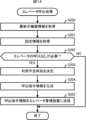
- FIG. 9 is a flowchart showing the procedure of the monitoring process executed by the cloud server 2.
- the cloud server 2 executes the following monitoring process at regular intervals (for example, every minute).
- Step S100 The cloud server 2 acquires device information from the device 3. After that, the process of the cloud server 2 transitions to step S101.
- Step S101 The cloud server 2 acquires elevator information from the elevator management device 5. After that, the process of the cloud server 2 transitions to step S102.
- Step S102 The cloud server 2 estimates the target person's behavior based on the history of equipment information, the history of elevator information, and the previous estimation result. After that, the process of the cloud server 2 transitions to step S103.
- Step S103 The cloud server 2 determines whether the user needs to be notified. Whether notification is necessary or not is determined based on the presence or absence of a change in behavior and the setting information stored in the setting information storage unit 240. As a result, if notification is required (step S103; YES), the process of the cloud server 2 transitions to step S104. On the other hand, if notification is not required (step S103; NO), the cloud server 2 ends the monitoring process in this cycle.
- Step S104 Cloud server 2 generates notification information. After that, the process of the cloud server 2 transitions to step S105.
- Step S105 The cloud server 2 transmits the generated notification information to the user terminal 6. After that, the cloud server 2 ends the monitoring process in this cycle.
- the user terminal 6 that has received the notification information displays a user notification screen as shown in FIG. 6 on the display 60, for example, by push notification.
- equipment information regarding the operation of the equipment 3 installed in the house H and elevator information regarding the operation of the elevator E installed in the building B to which the house H belongs are stored. Estimate the target person's behavior based on the Therefore, it is possible to improve reliability while respecting privacy in detecting whether or not the subject is out.
- the device 3 is not limited to home appliances, and may be a human sensor that detects a person using infrared rays, visible light, sound waves, sound sense, etc., for example. Further, the router 4 may function as the device 3. That is, the router 4 may transmit device information, which is information regarding its own operation, to the cloud server 2 at regular intervals (for example, every minute).
- a plurality of devices 3 communicably connected to the cloud server 2 may be installed in the target person's residence H. In this case, if there are multiple devices 3 equipped with human sensors, and if a person is detected by any of the human sensors, the behavior estimation unit 203 of the cloud server 2 determines whether the target person is going out or not. Exclude.
- the device 3 may voluntarily transmit the device information to the cloud server 2 using a change in the operating state as a trigger.
- the device 3 equipped with the human sensor spontaneously transmits device information to the cloud server 2 not only when the operating state changes but also when the detection result of the human sensor changes.
- the cloud server 2 may send the notification information to the user terminal 6 by email.
- Modification 5 There may be multiple people involved with one target person. In this case, the cloud server 2 transmits similar notification information to the user terminals 6 of each person involved.
- the setting reception unit 200 of the cloud server 2 can be used only by related parties.
- the notification unit 204 may also receive settings for information regarding the monitoring service from the target person, or the notification unit 204 may send notification information to the terminal device.
- the notification unit 204 may also take into account the device information stored in the device information storage unit 241 to generate the notification information. For example, if the subject goes out without stopping the operation of the device 3, the notification unit 204 generates notification information that includes information to that effect and the current time, and transmits it to the user terminal 6.
- FIG. 10 shows an example of a user notification screen displayed on the display 60 of the user terminal 6 in this case. Further, even though the target person is at home, if the operating state of the device 3 remains in the stopped state after exceeding the predetermined upper limit stop time, the notification unit 204 sends information to that effect and the current time. The notification information containing the information is generated and sent to the user terminal 6.
- FIG. 11 shows an example of a user notification screen displayed on the display 60 of the user terminal 6 in this case.
- the behavior estimation unit 203 may estimate whether the person is going out, coming home, going out, or staying at home, and may also estimate whether the person is preparing to go out. Specifically, the behavior estimation unit 203 calculates the behavior estimation unit 203 when the previous estimation result indicates that the user is at home and the operating state of the device 3 changes from operating to stopped state (or when the human detection result by the human sensor If the detection changes from detection to non-detection), the period from when the elevator E arrives at the floor where the subject resides until the subject moves to the first floor is estimated to be the time when the subject is preparing to go out.
- the behavior estimation unit 203 determines that an abnormality such as poor physical condition has occurred in the target person, and the notification unit 204 determines that an abnormality has occurred while the target person is preparing to go out.
- the user terminal 6 may be notified that there is a possibility that this has occurred.
- the behavior estimation unit 203 may estimate the time immediately before or after returning home. Specifically, if the previous estimation result indicates that the subject is out, and the elevator E moves from the first floor to the floor where the subject resides, the behavior estimation unit 203 determines whether the operating state of the device 3 changes from the stopped state to the next. The period until the change occurs during operation (or until the human detection result by the human sensor changes from undetected to detected) is estimated to be immediately before or after returning home. In addition, the behavior estimation unit 203 determines that an abnormality such as poor physical condition has occurred in the subject if the condition immediately before or after returning home continues for 4 hours or more, and the notification unit 204 determines that the subject has experienced an abnormality such as poor physical condition. Immediately after returning home, the user terminal 6 may be notified that an abnormality may have occurred.
- the user can determine the third and fourth hours based on the subject's daily behavior and set them in the cloud server 2 using the monitoring app.
- the cloud server 2 may be composed of a plurality of separate servers. In this case, for example, there is a device information management server that acquires and manages device information from the device 3, an elevator information management server that acquires and manages elevator information from the elevator management device 5, and a device information management server that acquires and manages the device information from the device information management server.
- the cloud server 2 may be configured by a monitoring server that monitors the target person based on the elevator information acquired from the elevator information management server.
- An identification information acquisition device for acquiring user identification information may be installed in the elevator E or at the boarding/alighting location on each floor of the elevator E.
- the identification information acquisition device is an example of first identification information acquisition means according to the present disclosure.
- the identification information acquisition device is communicably connected to the elevator management device 5 and transmits user information including the acquired user identification information and the current date and time to the elevator management device 5.
- the elevator management device 5 transmits the user information received from the identification information acquisition device to the cloud server 2.
- the setting information stored in the setting information storage unit 240 of the cloud server 2 includes identification information of the target person set in advance by a person concerned. By doing so, the behavior estimation unit 203 of the cloud server 2 can use the user information received from the elevator management device 5 to estimate the behavior of the target person with higher accuracy.
- the cloud server 2 can understand that the subject has entered the elevator E to go home, it is possible to operate the device 3 before the subject returns home. Therefore, it becomes possible to turn on a lighting device or start air conditioning in an air conditioner before the subject returns home, improving the subject's comfort.
- the above-mentioned identification information acquisition device is, for example, a receiver that receives a wireless signal periodically transmitted through BLE (Bluetooth (registered trademark) Low Energy) communication from a mobile terminal such as a mobile phone or a smartphone owned by the target person. It is a device.
- a wireless signal includes identification information (for example, ID (identifier)) of the subject.
- the identification information acquisition device may be an IC tag reader that reads information including identification information (for example, ID) of the target person from an IC tag worn by the target person.
- the identification information acquisition device may be a device that collects a fingerprint of the target person as the target person's identification information, or a CCD (Charge-Coupled Device) that acquires a facial image of the target person as the target person's identification information.
- a visible camera configured with an image sensor such as CMOS (Complementary Metal Oxide Semiconductor).
- a transmitter that periodically transmits a radio signal containing floor number information indicating the floor number may be installed at the boarding/alighting location of each floor of the elevator E.
- the transmitter is an example of a first transmitter according to the present disclosure.
- a mobile terminal such as a mobile phone or a smartphone owned by the subject receives the wireless signal transmitted from the transmitter, acquires the floor information, and obtains the identification information (e.g. ID) of the subject.
- Location information including floor number information and current time is transmitted to the cloud server 2.
- the behavior estimation unit 203 of the cloud server 2 can estimate the target person's behavior with higher accuracy by using the position information received from the target person's mobile terminal.
- the cloud server 2 can understand that the subject has entered the elevator E to go home, it is possible to operate the device 3 before the subject returns home. Therefore, it becomes possible to turn on a lighting device or start air conditioning in an air conditioner before the subject returns home, improving the subject's comfort.
- the identification information acquisition device of Modified Example 10 is installed at the elevator or the boarding and alighting place on each floor of the elevator, and the elevator management device 5 similar to Modified Example 10 is installed. You can also do this.
- the identification information acquisition device is an example of second identification information acquisition means according to the present disclosure. By doing so, if the target person stops by one of the plurality of buildings when going out, the notification unit 204 of the cloud server 2 can notify related parties of the target person's specific location. It becomes possible.
- the cloud server 2 will be able to monitor the target person's outings during that time period. It becomes possible to determine whether or not there is. For example, if the user has not visited the building during the time period, or has visited a different building, the notification unit 204 of the cloud server 2 transmits notification information indicating this to the user terminal 6. Thereby, the person concerned can grasp whether or not the subject has successfully arrived at the destination.
- the transmitter of modification 11 may be installed at the boarding and alighting locations of each elevator floor.
- the transmitter is an example of a second transmitter according to the present disclosure.
- the monitoring system 1 may be applied to watch over a resident (i.e., a target person) of a house equipped with a home elevator.
- a resident i.e., a target person
- the subject's home corresponds to building B
- the home elevator corresponds to elevator E
- each room in the home corresponds to house H.
- the equipment information of the equipment 3 installed in each room and the elevator information it is possible to monitor the entry and exit of the subject from each room.
- the monitoring system 1 may be applied to monitoring employees in an office building.
- the employee is the target person
- the office building is equivalent to Building B
- the elevator in the office building is equivalent to Elevator E
- each room and other predetermined locations in the office building are residential buildings. This corresponds to H.
- the monitoring system 1 of this modification by predetermining the relationship between the equipment 3 installed in each room etc. and the target person, using the equipment information and elevator information of the equipment 3 related to the target person, The behavior of subjects within an office building can be monitored.
- the monitoring system 1 can be applied to watch over one or more subjects such as patients, care recipients, students, etc. in hospitals, nursing care facilities, schools, etc.
- An IC tag reader that reads information from IC tags attached to articles may be installed in the elevator E, and the information read by the IC tag reader may be transmitted to the cloud server 2 via the elevator management device 5. In this way, it becomes possible to monitor whether items in house H have been illegally taken out by a third party other than the subject.
- All or part of the functional units (see FIG. 4) of the cloud server 2 may be realized by dedicated hardware.
- the dedicated hardware is, for example, a single circuit, a composite circuit, a programmed processor, an ASIC (Application Specific Integrated Circuit), an FPGA (Field-Programmable Gate Array), or a combination thereof.
- Embodiment 2 Next, a second embodiment of the present disclosure will be described. Note that in the following description, the same components and the like as those in Embodiment 1 are given the same reference numerals, and the description thereof will be omitted.
- FIG. 12 is a diagram showing the overall configuration of a monitoring system 1A in Embodiment 2 of the present disclosure.
- the monitoring system 1A is an example of a monitoring system according to the present disclosure, and it monitors the residents of a house H (hereinafter referred to as "target persons"), which is an example of a person to be monitored according to the present disclosure, and also monitors the use of elevators by the target persons.
- target persons which is an example of a person to be monitored according to the present disclosure
- the monitoring system 1A includes a cloud server 2A, a device 3 and a router 4 installed in a house H, an elevator management device 5A installed in a building B such as an apartment to which the house H belongs, and a user terminal 6. Note that the house H is located on the second or higher floor of the building B.
- the cloud server 2A is an example of a server according to the present disclosure.
- the cloud server 2A is a server computer installed and operated by the manufacturer, sales company, etc. of the equipment 3 and the elevator E installed in the building B, and is connected to the network N, which is a wide area network such as the Internet.
- the hardware configuration of cloud server 2A is similar to cloud server 2 of Embodiment 1 (see FIG. 2). Details of the functions of the cloud server 2A will be described later.
- the elevator management device 5A is an example of elevator management means according to the present disclosure.
- the elevator management device 5A is a computer that manages the operation of the elevator E installed in the building B.
- the elevator management device 5A includes hardware for communicating with the cloud server 2A via the network N, and periodically (for example, every minute), the elevator management device 5A Elevator information, which is information regarding the operation of the elevator, is transmitted to the cloud server 2A.
- the elevator management device 5A also controls the movement of the elevator E to the floor where the target person resides in accordance with a command from the cloud server 2A.
- FIG. 13 is a block diagram showing the functional configuration of the cloud server 2A.
- the cloud server 2A includes a setting reception section 200, a device information acquisition section 201, an elevator information acquisition section 202, an action estimation section 203, a notification section 204, and a call command section 205.
- These functional units are realized by the CPU 21 of the cloud server 2A executing the monitoring program and elevator usage support program stored in the auxiliary storage device 24.
- the monitoring program is a program to monitor the behavior of the target person who is a resident of House H, and to notify the relevant person of the target person of information based on the monitoring results. This is a program to support the use of elevator E.
- the functions of the setting reception unit 200, device information acquisition unit 201, elevator information acquisition unit 202, behavior estimation unit 203, and notification unit 204 are the same as those in the cloud server 2 of the first embodiment.
- the call command unit 205 is an example of a call command means according to the present disclosure.
- the call command unit 205 instructs the elevator management device 5A to call the elevator E when it is necessary to call the elevator E to the floor where the subject resides.
- the call command unit 205 sends a message to the target person's residence floor based on the latest equipment information stored in the equipment information storage unit 241 and the setting information stored in the setting information storage unit 240. Determine whether it is necessary to call elevator E.
- the call command unit 205 calls the elevator E to the floor where the target person resides. It is determined that this is necessary.
- the scheduled elevator use time period is a time period in which the subject is likely to use the elevator E, and is set in advance by a user who is a related party via a monitoring application.
- the call command unit 205 changes the operating state of the device 3 from in operation to when the detection result by the human sensor changes from detected to undetected. Even if the state has not changed to the stopped state, it may be determined that it is necessary to call the elevator E to the floor where the subject resides if the elevator is scheduled to be used.
- the call command unit 205 When the call command unit 205 determines that it is necessary to call the elevator E to the target person's residence floor, the call command unit 205 generates call command information and transmits it to the elevator management device 5A.
- the call command information includes information indicating the call floor (that is, the target person's residence floor) and the scheduled time of use.
- the scheduled usage time is the time when the target person is scheduled to arrive at the elevator boarding and alighting location on the called floor.
- the scheduled usage time is determined by adding the time required for the target person to move (hereinafter referred to as "required travel time") to the current time.
- the user can determine the travel time required from the subject's daily behavior and set it in the cloud server 2A using the monitoring app.
- the user may use the monitoring app to set the distance from the entrance of house H to the elevator boarding and alighting location on the residential floor, and the cloud server 2A may determine the travel time based on the set distance.
- the cloud server 2A may derive the required travel time through learning.
- the elevator management device 5A controls the operation of the elevator E so that the elevator E arrives at the called floor by the scheduled time of use.
- FIG. 14 is a flowchart showing the procedure of elevator calling processing executed by the cloud server 2A.
- the cloud server 2A executes the following elevator calling process at regular intervals (for example, every minute) in parallel with the above-mentioned monitoring process.
- Step S200 The cloud server 2A acquires the latest device information from the device information storage section 241. After that, the process of the cloud server 2A transitions to step S201.
- Step S201 The cloud server 2A reads and acquires the setting information from the setting information storage unit 240. After that, the process of the cloud server 2A transitions to step S202.
- Step S202 The cloud server 2A determines whether or not it is necessary to call the elevator E to the target person's residence floor based on the latest equipment information and the scheduled elevator use time period included in the setting information. As a result, if it is necessary to call the elevator E to the target person's residence floor (step S202; YES), the process of the cloud server 2A transitions to step S203. On the other hand, if it is not necessary to call the elevator E to the target person's residence floor (step S202; NO), the cloud server 2A ends the elevator calling process in this cycle.
- Step S203 The cloud server 2A determines the scheduled usage time based on the current time and the required travel time. After that, the process of the cloud server 2A transitions to step S204.
- Step S204 The cloud server 2A generates call command information that includes information indicating a call floor and a scheduled time of use. After that, the process of the cloud server 2A transitions to step S205.
- Step S205 The cloud server 2A transmits the generated call command information to the elevator management device 5A. After that, the cloud server 2A ends the elevator calling process in this cycle.
- the elevator management device 5A that has received the call command information controls the operation of the elevator E so that the elevator E arrives at the floor where the target person resides by the scheduled time of use by the target person.
- equipment information regarding the operation of the equipment 3 installed in the house H and elevator information regarding the operation of the elevator E installed in the building B to which the house H belongs are stored. Estimate the target person's behavior based on the Therefore, it is possible to improve reliability while respecting privacy in detecting whether or not the subject is out.
- the elevator E can be automatically moved to the floor where the subject resides when the subject goes out, the convenience of the subject when going out is significantly improved.
- Modification 1 When the configuration of the modification 12 of the first embodiment is added to the monitoring system 1A, and the behavior estimation unit 203 estimates that the target person stopped at one of the plurality of buildings when going out, a call command is issued.
- the department 205 may call the elevator E to the first floor.
- the call command unit 205 determines the time required for returning home, which is preset corresponding to the building, after the behavior estimation unit 203 estimates that the target person has stopped at one of the plurality of buildings. Once the time has elapsed, the elevator E may be called to the first floor. The user can use the monitoring app to set the required return time corresponding to each building in the cloud server 2A. In this way, when a subject who has stopped by one of the above-mentioned buildings arrives at building B on his way home, there is a high possibility that he will be able to use elevator E immediately. The convenience of the service will be significantly improved.
- Modification 2 When the configuration of Modified Example 13 of Embodiment 1 is added to the monitoring system 1A, and the behavior estimation unit 203 estimates that the target person stopped by one of the plurality of buildings when going out, a call command is issued.
- the department 205 may call the elevator E to the first floor.
- the call command unit 205 after the behavior estimation unit 203 estimates that the target person has stopped by one of the plurality of buildings, responds to the building in response to the said building.
- the elevator E When a preset time required for returning home has elapsed, the elevator E may be called to the first floor.
- All or part of the functional units (see FIG. 13) of the cloud server 2A may be realized by dedicated hardware.
- Dedicated hardware can be, for example, a single circuit, a complex circuit, a programmed processor, an ASIC, an FPGA, or a combination thereof.
- Modification 4 Modifications 1 to 15 of Embodiment 1 can also be applied to this embodiment.
- the present disclosure can be suitably employed in technology for watching over elderly people, disabled people, etc.
Landscapes
- Business, Economics & Management (AREA)
- Health & Medical Sciences (AREA)
- General Physics & Mathematics (AREA)
- General Health & Medical Sciences (AREA)
- Tourism & Hospitality (AREA)
- Physics & Mathematics (AREA)
- Emergency Management (AREA)
- Child & Adolescent Psychology (AREA)
- Gerontology & Geriatric Medicine (AREA)
- Economics (AREA)
- Human Resources & Organizations (AREA)
- Marketing (AREA)
- Primary Health Care (AREA)
- Strategic Management (AREA)
- General Business, Economics & Management (AREA)
- Engineering & Computer Science (AREA)
- Theoretical Computer Science (AREA)
- Alarm Systems (AREA)
Abstract
監視システムは、住宅に設置された機器の動作に関する機器情報を取得する機器情報取得部(201)と、住宅が属する建物に設置されたエレベータの運行に関するエレベータ情報を取得するエレベータ情報取得部(202)と、機器情報を記憶する機器情報記憶部(241)と、エレベータ情報を記憶するエレベータ情報記憶部(242)と、機器情報記憶部(241)に記憶される機器情報と、エレベータ情報記憶部(242)に記憶されるエレベータ情報とに基づいて、見守り対象者の行動を推定する行動推定部(203)とを備える。
Description
本開示は、監視システム、サーバ及び監視方法に関する。
従来、独居老人等の高齢者の見守りに関する技術について様々な提案がなされている。例えば、特許文献1には、見守り対象者が監視されているという認識を持たずに済むように、見守り対象者の家庭に設置された照明装置の点灯/消灯によって見守り対象者の行動を把握する安否確認システムについて記載されている。
この安否確認システムでは、クラウドサーバが、見守り対象者の家庭における照明装置の点灯/消灯の履歴を参照して、予め設定登録された安否通知ルールに従い安否情報を生成する。そして、クラウドサーバは、生成した安否情報を見守り対象者の別居家族、ケアマネージャ等の見守り者が所持する外部端末へ送信する。
ところで、このような見守りにおいては、見守り対象者の住宅内の行動のみならず、見守り対象者の外出の有無についても検出すべき重要な状況といえる。
この場合、例えば、当該住宅内の随所に人感センサを設置することで、高い確度で見守り対象者の外出を検出することが可能である。しかし、コストが嵩むとともに、見守り対象者に不快感を与えてしまうという懸念がある。
また、GPS(Global Positioning System)機能が搭載された、携帯電話、スマートフォン等の携帯端末を見守り対象者が常時携帯するようにすれば、見守り対象者の現在位置を把握できるため、見守り対象者の外出の有無を確認することが可能である。しかし、見守り対象者が当該携帯端末を必ず携帯しているとは限らず、外出の有無の判断の根拠としては、信頼性に乏しいという問題がある。
したがって、見守り対象者の外出有無の検出について、プライバシーを尊重しつつ、信頼性の向上を図るための新たな技術の提案が望まれているのが実情である。
本開示は、上記実情に鑑みてなされたものであり、見守り対象者の外出有無の検出について、プライバシーを尊重しつつ、信頼性の向上を図ることが可能な監視システム、サーバ及び監視方法を提供することを目的とする。
上記目的を達成するため、本開示に係る監視システムは、
住宅に設置された機器の動作に関する機器情報を取得する機器情報取得手段と、
前記住宅が属する建物に設置されたエレベータの運行に関するエレベータ情報を取得するエレベータ情報取得手段と、
前記機器情報を記憶する機器情報記憶手段と、
前記エレベータ情報を記憶するエレベータ情報記憶手段と、
前記機器情報記憶手段に記憶される機器情報と、前記エレベータ情報記憶手段に記憶されるエレベータ情報とに基づいて、見守り対象者の行動を推定する行動推定手段と、を備える。
住宅に設置された機器の動作に関する機器情報を取得する機器情報取得手段と、
前記住宅が属する建物に設置されたエレベータの運行に関するエレベータ情報を取得するエレベータ情報取得手段と、
前記機器情報を記憶する機器情報記憶手段と、
前記エレベータ情報を記憶するエレベータ情報記憶手段と、
前記機器情報記憶手段に記憶される機器情報と、前記エレベータ情報記憶手段に記憶されるエレベータ情報とに基づいて、見守り対象者の行動を推定する行動推定手段と、を備える。
本開示によれば、住宅に設置された機器の動作に関する機器情報と、当該住宅が属する建物に設置されたエレベータの運行に関するエレベータ情報とに基づいて見守り対象者の行動を推定するため、見守り対象者の外出有無の検出について、プライバシーを尊重しつつ、信頼性の向上を図ることが可能となる。
以下、本開示の実施の形態について図面を参照して詳細に説明する。
(実施の形態1)
図1は、本開示の実施の形態1における監視システム1の全体構成を示す図である。監視システム1は、本開示に係る監視システムの一例であり、本開示に係る見守り対象者の一例である住宅Hの居住者(以下「対象者」という。)を見守るためのシステムである。監視システム1は、クラウドサーバ2と、住宅Hに設置される機器3及びルータ4と、住宅Hが属するマンション等の建物Bに設置されるエレベータ管理装置5と、ユーザ端末6とを備える。なお、住宅Hは、建物Bの2階以上の階に位置する。
図1は、本開示の実施の形態1における監視システム1の全体構成を示す図である。監視システム1は、本開示に係る監視システムの一例であり、本開示に係る見守り対象者の一例である住宅Hの居住者(以下「対象者」という。)を見守るためのシステムである。監視システム1は、クラウドサーバ2と、住宅Hに設置される機器3及びルータ4と、住宅Hが属するマンション等の建物Bに設置されるエレベータ管理装置5と、ユーザ端末6とを備える。なお、住宅Hは、建物Bの2階以上の階に位置する。
<クラウドサーバ2>
クラウドサーバ2は、本開示に係るサーバの一例である。クラウドサーバ2は、機器3及び建物Bに設置されるエレベータEのメーカ、販売会社等によって設置及び運用されるサーバコンピュータであり、インターネット等の広域ネットワークであるネットワークNに接続される。図2に示すように、クラウドサーバ2は、通信インタフェース20と、CPU(Central Processing Unit)21と、ROM(Read Only Memory)22と、RAM(Random Access Memory)23と、補助記憶装置24とを備える。これらの構成部は、バス25を介して相互に接続される。
クラウドサーバ2は、本開示に係るサーバの一例である。クラウドサーバ2は、機器3及び建物Bに設置されるエレベータEのメーカ、販売会社等によって設置及び運用されるサーバコンピュータであり、インターネット等の広域ネットワークであるネットワークNに接続される。図2に示すように、クラウドサーバ2は、通信インタフェース20と、CPU(Central Processing Unit)21と、ROM(Read Only Memory)22と、RAM(Random Access Memory)23と、補助記憶装置24とを備える。これらの構成部は、バス25を介して相互に接続される。
通信インタフェース20は、ネットワークNを介して他の装置と通信するためのハードウェアである。CPU21は、クラウドサーバ2を統括的に制御する。CPU21によって実現されるクラウドサーバ2の機能の詳細については後述する。ROM22は、複数のファームウェア及びこれらのファームウェアの実行時に使用されるデータを記憶する。RAM23は、CPU21の作業領域として使用される。
補助記憶装置24は、読み書き可能な不揮発性の半導体メモリ、HDD(Hard Disk Drive)等で構成される。読み書き可能な不揮発性の半導体メモリは、例えば、EEPROM(Electrically Erasable Programmable Read-Only Memory)、フラッシュメモリ等である。補助記憶装置24には、住宅Hの居住者である対象者の行動を監視し、監視結果に基づく情報を当該対象者の関係者に通知するためのプログラム(以下「監視プログラム」という。)を含む各種のプログラムと、これらのプログラムの実行時に使用されるデータとが記憶される。関係者には、例えば、対象者の親族、介護支援サービスの担当者、建物Bを管理する会社の担当者等が含まれる。
クラウドサーバ2は、上記の監視プログラム又は監視プログラムを更新するための更新プログラムを他のサーバからネットワークNを介した通信により取得することが可能である。また、これらのプログラムは、CD-ROM(Compact Disc Read Only Memory)、DVD(Digital Versatile Disc)、光磁気ディスク、USB(Universal Serial Bus)メモリ、HDD、SSD(Solid State Drive)、メモリカード等のコンピュータ読み取り可能な記録媒体に格納して配布することも可能である。クラウドサーバ2は、そのような記録媒体が自身に直接又は間接的に装着されると、当該記録媒体から監視プログラム又は更新プログラムを読み出して取り込むことも可能である。
<機器3>
機器3は、本開示に係る機器の一例である。機器3は、例えば、いわゆるIoT(Internet of Things)機器、情報家電、ネット家電、スマート家電等と称される家電機器であり、例えば、エアコン、照明装置、テレビ等である。機器3は、Wi-Fi(登録商標)等の無線LAN(Local Area Network)ルータであるルータ4と無線にて通信接続し、ルータ4を介してクラウドサーバ2と通信するためのハードウェアを備える。
機器3は、本開示に係る機器の一例である。機器3は、例えば、いわゆるIoT(Internet of Things)機器、情報家電、ネット家電、スマート家電等と称される家電機器であり、例えば、エアコン、照明装置、テレビ等である。機器3は、Wi-Fi(登録商標)等の無線LAN(Local Area Network)ルータであるルータ4と無線にて通信接続し、ルータ4を介してクラウドサーバ2と通信するためのハードウェアを備える。
機器3は、一定時間毎に(例えば1分毎に)、自身の動作に関する情報(以下「機器情報」という。)をクラウドサーバ2に送信する。機器情報には、機器3を一意に識別可能な識別情報、現在日時、動作状態を示す情報、当該機器3が備えるセンサ(例えば、赤外線サーモグラフィ等の熱画像センサ、温度センサ等)の計測結果等が含まれる。機器3の識別情報は、例えば、機器3の製造番号、IPアドレス等である。
動作状態には、動作中か停止状態かを示す情報と、動作内容とが含まれる。例えば、機器3がエアコンの場合、動作内容には、冷房、暖房、送風、除湿等を示す運転モードと、設定温度、風速、タイマ設定の設定内容等とが含まれる。また、機器3が照明装置の場合、動作内容には、出力レベル等が含まれ、機器3がテレビの場合、動作内容には、チャンネルと、音量等とが含まれる。なお、機器3は、外付けの図示しない通信アダプタを介してクラウドサーバ2と通信する構成であってもよい。
<エレベータ管理装置5>
エレベータ管理装置5は、建物Bに設置されているエレベータEの運行を管理するコンピュータである。エレベータ管理装置5は、ネットワークNを介してクラウドサーバ2と通信するためのハードウェアを備える。エレベータ管理装置5は、一定時間毎に(例えば1分毎に)、エレベータEの運行に関する情報(以下「エレベータ情報」という。)をクラウドサーバ2に送信する。エレベータ情報には、エレベータEを一意に識別可能な識別情報と、現在日時と、エレベータEの利用者が指定した行先を示す行先指定情報と、当該一定時間の間におけるエレベータEの運行実績とが含まれる。
エレベータ管理装置5は、建物Bに設置されているエレベータEの運行を管理するコンピュータである。エレベータ管理装置5は、ネットワークNを介してクラウドサーバ2と通信するためのハードウェアを備える。エレベータ管理装置5は、一定時間毎に(例えば1分毎に)、エレベータEの運行に関する情報(以下「エレベータ情報」という。)をクラウドサーバ2に送信する。エレベータ情報には、エレベータEを一意に識別可能な識別情報と、現在日時と、エレベータEの利用者が指定した行先を示す行先指定情報と、当該一定時間の間におけるエレベータEの運行実績とが含まれる。
<ユーザ端末6>
ユーザ端末6は、本開示に係る端末装置の一例である。ユーザ端末6は、上述した関係者によって所持される電子機器であり、例えば、スマートフォン、タブレット端末等のスマートデバイスである。
ユーザ端末6は、本開示に係る端末装置の一例である。ユーザ端末6は、上述した関係者によって所持される電子機器であり、例えば、スマートフォン、タブレット端末等のスマートデバイスである。
図3に示すように、ユーザ端末6は、ディスプレイ60と、操作受付部61と、通信インタフェース62と、CPU63と、ROM64と、RAM65と、補助記憶装置66とを備える。これらの構成部は、バス67を介して相互に接続される。
ディスプレイ60は、液晶ディスプレイ、有機EL(Electro Luminescence)ディスプレイ等の表示デバイスを含んで構成される。ディスプレイ60は、CPU63の制御の下、ユーザ(すなわち、対象者の関係者)の操作に応じた各種の画面等を表示する。
操作受付部61は、押しボタン、タッチパネル、タッチパッド等の1つ以上の入力デバイスを含んで構成され、ユーザからの操作入力を受け付け、受け付けた操作に係る信号をCPU63に出力する。
通信インタフェース62は、ネットワークNを介して他の装置と通信するためのハードウェアである。CPU63は、ユーザ端末6を統括的に制御する。ROM64は、複数のファームウェア及びこれらのファームウェアの実行時に使用されるデータを記憶する。RAM65は、CPU63の作業領域として使用される。
補助記憶装置66は、EEPROM、フラッシュメモリ等の読み書き可能な不揮発性の半導体メモリ等を含んで構成される。補助記憶装置66には、監視システム1によって提供される見守りサービスを受けるためのアプリケーションプログラム(以下「見守りアプリ」という。)を含む各種のプログラムと、これらのプログラムの実行時に使用されるデータとが記憶される。
ユーザ端末6は、見守りアプリ又は見守りアプリを更新するための更新プログラムをクラウドサーバ2又はその他のサーバから通信によって取得することが可能である。また、これらのプログラムは、CD-ROM、DVD、光磁気ディスク、USBメモリ、HDD、SSD、メモリカード等のコンピュータ読み取り可能な記録媒体に格納して配布することも可能である。ユーザ端末6は、そのような記録媒体が自身に直接又は間接的に装着された場合、当該記録媒体から見守りアプリ又は更新プログラムを読み出して取得してもよい。
<クラウドサーバ2の機能構成>
図4は、クラウドサーバ2の機能構成を示すブロック図である。図4に示すように、クラウドサーバ2は、設定受付部200と、機器情報取得部201と、エレベータ情報取得部202と、行動推定部203と、通知部204とを備える。これらの機能部は、CPU21が補助記憶装置24に記憶されている上述した監視プログラムを実行することで実現される。
図4は、クラウドサーバ2の機能構成を示すブロック図である。図4に示すように、クラウドサーバ2は、設定受付部200と、機器情報取得部201と、エレベータ情報取得部202と、行動推定部203と、通知部204とを備える。これらの機能部は、CPU21が補助記憶装置24に記憶されている上述した監視プログラムを実行することで実現される。
設定受付部200は、関係者であるユーザから見守りサービスに関する情報の設定を受け付ける。ユーザは、見守りアプリを使用して、様々な情報をユーザ端末6を介して設定することができる。例えば、ユーザは、対象者の氏名、対象者の住所、機器3の識別情報、通知条件等をユーザ端末6を介して設定することができる。機器3の識別情報については、ユーザが対象者の住宅Hで見守りアプリを使用することで、機器3から自動的に取得して設定することができる。設定受付部200は、ユーザから受け付けた設定に関する設定情報を設定情報記憶部240に保存する。設定情報記憶部240は、補助記憶装置24によって提供されるメモリ領域である。
機器情報取得部201は、本開示に係る機器情報取得手段の一例である。機器情報取得部201は、対象者の住宅Hに設置された機器3から送られてくる上述の機器情報を受信して取得する。機器情報は、クラウドサーバ2からの要求に応答して機器3から送信される仕様でもよいし、機器3から自発的に送信される仕様でもよい。機器情報取得部201は、取得した機器情報を時系列で分別して機器情報記憶部241に保存する。つまり、機器情報記憶部241には、機器情報の履歴が保存される。機器情報記憶部241は、補助記憶装置24によって提供されるメモリ領域であり、本開示にかかる機器情報記憶手段の一例である。
エレベータ情報取得部202は、本開示に係るエレベータ情報取得手段の一例である。エレベータ情報取得部202は、対象者の住宅Hが属する建物Bに設置されたエレベータ管理装置5から送られてくる上述のエレベータ情報を受信して取得する。エレベータ情報は、クラウドサーバ2からの要求に応答してエレベータ管理装置5から送信される仕様でもよいし、エレベータ管理装置5から自発的に送信される仕様でもよい。エレベータ情報取得部202は、取得したエレベータ情報を時系列で分別してエレベータ情報記憶部242に保存する。つまり、エレベータ情報記憶部242には、エレベータ情報の履歴が保存される。エレベータ情報記憶部242は、補助記憶装置24によって提供されるメモリ領域であり、本開示にかかるエレベータ情報記憶手段の一例である。
行動推定部203は、本開示に係る行動推定手段の一例である。行動推定部203は、機器情報記憶部241に記憶されている機器情報と、エレベータ情報記憶部242に記憶されているエレベータ情報とに基づいて、対象者の行動を推定する。詳細には、行動推定部203は、機器情報及びエレベータ情報の履歴と、前回の推定結果とに基づいて、対象者の行動を推定する。本実施の形態では、行動推定部203は、対象者の行動として、外出、帰宅、外出中及び在宅中のいずれかを推定する。以下、それぞれの推定手法について説明する。
<外出の推定>
図5に示すように、行動推定部203は、前回の推定結果が在宅中であり、且つ、機器3の動作状態が動作中から停止状態に変化した後、第1時間以上且つ第2時間以内にエレベータEが対象者の居住階に到着し、1階に移動した場合、外出の要件を満たすとして、対象者が外出したと推定する。第1時間及び第2時間は、例えば次のような時間を意味する。すなわち、機器3の動作状態が動作中から停止状態に変化した際の対象者の行動が、住宅Hを出た又は外出の準備を始めたと仮定した場合、第1時間は、対象者が住宅Hを出てからエレベータEを利用するまでの最短の所要時間を意味し、第2時間は、対象者が外出の準備を始めてからエレベータEを利用するまでの最長の所要時間を意味する。
図5に示すように、行動推定部203は、前回の推定結果が在宅中であり、且つ、機器3の動作状態が動作中から停止状態に変化した後、第1時間以上且つ第2時間以内にエレベータEが対象者の居住階に到着し、1階に移動した場合、外出の要件を満たすとして、対象者が外出したと推定する。第1時間及び第2時間は、例えば次のような時間を意味する。すなわち、機器3の動作状態が動作中から停止状態に変化した際の対象者の行動が、住宅Hを出た又は外出の準備を始めたと仮定した場合、第1時間は、対象者が住宅Hを出てからエレベータEを利用するまでの最短の所要時間を意味し、第2時間は、対象者が外出の準備を始めてからエレベータEを利用するまでの最長の所要時間を意味する。
例えば、ユーザは、当該対象者の日常的な行動から第1時間及び第2時間を決定し、見守りアプリを使用してクラウドサーバ2に設定することが可能である。あるいは、ユーザは、見守りアプリを使用して住宅Hの玄関から居住階のエレベータ乗降場所までの距離を設定し、クラウドサーバ2が、設定された距離に基づいて第1時間及び第2時間を決定してもよい。あるいは、クラウドサーバ2は、学習により第1時間及び第2時間を導出してもよい。
なお、事前のタイマ設定により機器3の動作状態が動作中から停止状態に変化した場合は、行動推定部203は、外出の要件を満たしていないと判定してもよい。また、機器3が熱画像センサ等の人感センサを備える場合は、行動推定部203は、当該人感センサによる人の検出結果が検出から未検出に変化した場合、機器3の動作状態が動作中から停止状態に変化していない場合であっても、その他の上記の条件を満たしていれば、対象者が外出したと推定してもよい。
<帰宅の推定>
図5に示すように、行動推定部203は、前回の推定結果が外出中であり、且つ、機器3の動作状態が停止状態から動作中に変化した後、帰宅の要件を満たすとして、対象者が帰宅したと推定する。なお、事前のタイマ設定により機器3の動作状態が停止状態から動作中に変化した場合は、行動推定部203は、帰宅の要件を満たしていないと判定してもよい。また、機器3が熱画像センサ等の人感センサを備える場合は、行動推定部203は、前回の推定結果が外出中であり、且つ、当該人感センサによる人の検出結果が未検出から検出に変化した場合、機器3の動作状態にかかわらず、対象者が帰宅したと推定する。
図5に示すように、行動推定部203は、前回の推定結果が外出中であり、且つ、機器3の動作状態が停止状態から動作中に変化した後、帰宅の要件を満たすとして、対象者が帰宅したと推定する。なお、事前のタイマ設定により機器3の動作状態が停止状態から動作中に変化した場合は、行動推定部203は、帰宅の要件を満たしていないと判定してもよい。また、機器3が熱画像センサ等の人感センサを備える場合は、行動推定部203は、前回の推定結果が外出中であり、且つ、当該人感センサによる人の検出結果が未検出から検出に変化した場合、機器3の動作状態にかかわらず、対象者が帰宅したと推定する。
<外出中の推定>
図5に示すように、行動推定部203は、前回の推定結果が外出又は外出中であり、且つ、上記の帰宅の要件を満たしていない場合、対象者は外出中であると推定する。
図5に示すように、行動推定部203は、前回の推定結果が外出又は外出中であり、且つ、上記の帰宅の要件を満たしていない場合、対象者は外出中であると推定する。
<在宅中の推定>
図5に示すように、行動推定部203は、前回の推定結果が帰宅又は在宅中であり、且つ、上記の外出の要件を満たしていない場合、対象者は在宅中であると推定する。
図5に示すように、行動推定部203は、前回の推定結果が帰宅又は在宅中であり、且つ、上記の外出の要件を満たしていない場合、対象者は在宅中であると推定する。
行動推定部203は、現在日時と推定結果とを含む行動情報を時系列で分別して行動情報記憶部243に保存する。つまり、行動情報記憶部243には、行動情報の履歴が保存される。行動情報記憶部243は、補助記憶装置24によって提供されるメモリ領域である。
通知部204は、本開示に係る通知手段の一例である。通知部204は、行動推定部203による推定結果に基づいて、見守りに関する情報を関係者であるユーザに通知する。例えば、通知部204は、対象者の行動に変化があった場合、外出又は帰宅したことを示す情報と、現在時刻とが含まれた通知情報を生成し、ユーザ端末6に送信する。かかる通知情報を受信したユーザ端末6は、例えばプッシュ通知により、図6に示すようなユーザ通知画面をディスプレイ60に表示する。
また、例えば、ユーザにより事前に設定された外出予定時間帯とは異なる時間帯に対象者が外出した場合、通知部204は、その旨を示す情報と、現在時刻とが含まれた通知情報を生成し、ユーザ端末6に送信する。
また、例えば、通知部204は、行動に変化がない場合であっても、一定時間毎に、在宅中又は外出中であることを示す情報と、現在時刻とが含まれた通知情報を生成し、ユーザ端末6に送信する。この場合にユーザ端末6のディスプレイ60に表示されるユーザ通知画面の一例を図7に示す。一定時間毎に通知情報を受信するか否かについて、ユーザは見守りアプリを使用して事前に設定することが可能である。また、受信する場合の時間間隔についても、ユーザは見守りアプリを使用して事前に設定することが可能である。また、一定時間毎に通知情報を受信する場合の時間帯について、ユーザは見守りアプリを使用して事前に設定することが可能である。
また、例えば、通知部204は、予め定めた外出上限時間を超えて外出が継続している場合、その旨を示す情報と、現在時刻とが含まれた通知情報を生成し、ユーザ端末6に送信する。この場合にユーザ端末6のディスプレイ60に表示されるユーザ通知画面の一例を図8に示す。ユーザは見守りアプリを使用して、外出上限時間を事前に設定することが可能である。
また、通知部204は、ユーザが見守りアプリを使用した操作に応じて、対象者の現在の状況又は対象者の行動の履歴を示す通知情報を生成し、ユーザ端末6に送信してもよい。この場合、ユーザ端末6において当該通知情報が受信されると、見守りアプリによって当該通知情報に基づく画面が表示される。
<監視処理>
図9は、クラウドサーバ2によって実行される監視処理の手順を示すフローチャートである。クラウドサーバ2は、一定時間毎に(例えば1分毎に)、以下の監視処理を実行する。
図9は、クラウドサーバ2によって実行される監視処理の手順を示すフローチャートである。クラウドサーバ2は、一定時間毎に(例えば1分毎に)、以下の監視処理を実行する。
(ステップS100)
クラウドサーバ2は、機器3から機器情報を取得する。その後、クラウドサーバ2の処理は、ステップS101に遷移する。
クラウドサーバ2は、機器3から機器情報を取得する。その後、クラウドサーバ2の処理は、ステップS101に遷移する。
(ステップS101)
クラウドサーバ2は、エレベータ管理装置5からエレベータ情報を取得する。その後、クラウドサーバ2の処理は、ステップS102に遷移する。
クラウドサーバ2は、エレベータ管理装置5からエレベータ情報を取得する。その後、クラウドサーバ2の処理は、ステップS102に遷移する。
(ステップS102)
クラウドサーバ2は、機器情報の履歴と、エレベータ情報の履歴と、前回の推定結果とに基づいて、対象者の行動を推定する。その後、クラウドサーバ2の処理は、ステップS103に遷移する。
クラウドサーバ2は、機器情報の履歴と、エレベータ情報の履歴と、前回の推定結果とに基づいて、対象者の行動を推定する。その後、クラウドサーバ2の処理は、ステップS103に遷移する。
(ステップS103)
クラウドサーバ2は、ユーザに通知が必要か否かを判定する。通知の要否は、行動の変化有無と、設定情報記憶部240に記憶されている設定情報とに基づいて決定される。その結果、通知が必要な場合(ステップS103;YES)、クラウドサーバ2の処理は、ステップS104に遷移する。一方、通知が必要でない場合(ステップS103;NO)、クラウドサーバ2は、本周期での監視処理を終了する。
クラウドサーバ2は、ユーザに通知が必要か否かを判定する。通知の要否は、行動の変化有無と、設定情報記憶部240に記憶されている設定情報とに基づいて決定される。その結果、通知が必要な場合(ステップS103;YES)、クラウドサーバ2の処理は、ステップS104に遷移する。一方、通知が必要でない場合(ステップS103;NO)、クラウドサーバ2は、本周期での監視処理を終了する。
(ステップS104)
クラウドサーバ2は、通知情報を生成する。その後、クラウドサーバ2の処理は、ステップS105に遷移する。
クラウドサーバ2は、通知情報を生成する。その後、クラウドサーバ2の処理は、ステップS105に遷移する。
(ステップS105)
クラウドサーバ2は、生成した通知情報をユーザ端末6に送信する。その後、クラウドサーバ2は、本周期での監視処理を終了する。通知情報を受信したユーザ端末6は、例えばプッシュ通知により図6に示すようなユーザ通知画面をディスプレイ60に表示する。
クラウドサーバ2は、生成した通知情報をユーザ端末6に送信する。その後、クラウドサーバ2は、本周期での監視処理を終了する。通知情報を受信したユーザ端末6は、例えばプッシュ通知により図6に示すようなユーザ通知画面をディスプレイ60に表示する。
以上説明したように、本実施の形態における監視システム1では、住宅Hに設置された機器3の動作に関する機器情報と、住宅Hが属する建物Bに設置されたエレベータEの運行に関するエレベータ情報とに基づいて対象者の行動を推定する。このため、対象者の外出有無の検出について、プライバシーを尊重しつつ、信頼性の向上を図ることが可能となる。
また、推定された対象者の行動に基づいて、見守りに関する有意な情報を対象者の親族等の関係者に適宜通知するため、関係者は、適切に対象者を見守ることが可能となる。
(変形例1)
機器3は、家電機器に限定されず、例えば、赤外線、可視光、音波、音感等により人を検出する人感センサであってもよい。また、ルータ4が機器3として機能してもよい。すなわち、ルータ4が、一定時間毎に(例えば1分毎に)、自身の動作に関する情報である機器情報をクラウドサーバ2に送信してもよい。
機器3は、家電機器に限定されず、例えば、赤外線、可視光、音波、音感等により人を検出する人感センサであってもよい。また、ルータ4が機器3として機能してもよい。すなわち、ルータ4が、一定時間毎に(例えば1分毎に)、自身の動作に関する情報である機器情報をクラウドサーバ2に送信してもよい。
(変形例2)
対象者の住宅Hに、クラウドサーバ2と通信可能に接続される複数の機器3が設置されていてもよい。この場合、人感センサを備える機器3が複数存在する場合、いずれかの人感センサで人が検出されている場合、クラウドサーバ2の行動推定部203は、対象者の行動から外出及び外出中を除外する。
対象者の住宅Hに、クラウドサーバ2と通信可能に接続される複数の機器3が設置されていてもよい。この場合、人感センサを備える機器3が複数存在する場合、いずれかの人感センサで人が検出されている場合、クラウドサーバ2の行動推定部203は、対象者の行動から外出及び外出中を除外する。
(変形例3)
機器3は、一定時間毎に機器情報をクラウドサーバ2に送信するのではなく、動作状態が変更したことをトリガとして、自発的に機器情報をクラウドサーバ2に送信してもよい。この場合、人感センサを備える機器3においては、動作状態が変更した場合に加え、当該人感センサの検出結果が変更した場合にも自発的に機器情報をクラウドサーバ2に送信する。
機器3は、一定時間毎に機器情報をクラウドサーバ2に送信するのではなく、動作状態が変更したことをトリガとして、自発的に機器情報をクラウドサーバ2に送信してもよい。この場合、人感センサを備える機器3においては、動作状態が変更した場合に加え、当該人感センサの検出結果が変更した場合にも自発的に機器情報をクラウドサーバ2に送信する。
(変形例4)
クラウドサーバ2は、電子メールによって通知情報をユーザ端末6に送信してもよい。
クラウドサーバ2は、電子メールによって通知情報をユーザ端末6に送信してもよい。
(変形例5)
一人の対象者に対して複数人の関係者が存在してもよい。この場合、クラウドサーバ2は、各関係者のユーザ端末6に同様の通知情報を送信する。
一人の対象者に対して複数人の関係者が存在してもよい。この場合、クラウドサーバ2は、各関係者のユーザ端末6に同様の通知情報を送信する。
(変形例6)
対象者が、ユーザ端末6(図3参照)と同様の端末装置を所持し、当該端末装置に見守りアプリがインストールされている場合には、クラウドサーバ2の設定受付部200は、関係者のみならず対象者からも見守りサービスに関する情報の設定を受け付けてもよいし、通知部204は、当該端末装置に通知情報を送信してもよい。
対象者が、ユーザ端末6(図3参照)と同様の端末装置を所持し、当該端末装置に見守りアプリがインストールされている場合には、クラウドサーバ2の設定受付部200は、関係者のみならず対象者からも見守りサービスに関する情報の設定を受け付けてもよいし、通知部204は、当該端末装置に通知情報を送信してもよい。
(変形例7)
通知部204は、機器情報記憶部241に記憶される機器情報も加味して、通知情報を生成してもよい。例えば、対象者が機器3の動作を停止しないで外出した場合、通知部204は、その旨を示す情報と、現在時刻とが含まれた通知情報を生成し、ユーザ端末6に送信する。この場合にユーザ端末6のディスプレイ60に表示されるユーザ通知画面の一例を図10に示す。また、対象者が在宅中にもかかわらず、予め定めた停止上限時間を超えて、機器3の動作状態が停止状態のままである場合、通知部204は、その旨を示す情報と、現在時刻とが含まれた通知情報を生成し、ユーザ端末6に送信する。この場合にユーザ端末6のディスプレイ60に表示されるユーザ通知画面の一例を図11に示す。
通知部204は、機器情報記憶部241に記憶される機器情報も加味して、通知情報を生成してもよい。例えば、対象者が機器3の動作を停止しないで外出した場合、通知部204は、その旨を示す情報と、現在時刻とが含まれた通知情報を生成し、ユーザ端末6に送信する。この場合にユーザ端末6のディスプレイ60に表示されるユーザ通知画面の一例を図10に示す。また、対象者が在宅中にもかかわらず、予め定めた停止上限時間を超えて、機器3の動作状態が停止状態のままである場合、通知部204は、その旨を示す情報と、現在時刻とが含まれた通知情報を生成し、ユーザ端末6に送信する。この場合にユーザ端末6のディスプレイ60に表示されるユーザ通知画面の一例を図11に示す。
(変形例8)
行動推定部203は、図5に示すように、外出、帰宅、外出中及び在宅中を推定する他、外出準備中を推定してもよい。具体的には、行動推定部203は、前回の推定結果が在宅中であり、且つ、機器3の動作状態が動作中から停止状態に変化した場合(あるいは、人感センサによる人の検出結果が検出から未検出に変化した場合)、以後、エレベータEが対象者の居住階に到着し、1階に移動するまでの間を外出準備中と推定する。また、行動推定部203は、外出準備中の状態が第3時間以上継続した場合、対象者に体調不良等の異常が発生したと判定し、通知部204は、対象者の外出準備中に異常が発生している可能性がある旨をユーザ端末6に通知してもよい。
行動推定部203は、図5に示すように、外出、帰宅、外出中及び在宅中を推定する他、外出準備中を推定してもよい。具体的には、行動推定部203は、前回の推定結果が在宅中であり、且つ、機器3の動作状態が動作中から停止状態に変化した場合(あるいは、人感センサによる人の検出結果が検出から未検出に変化した場合)、以後、エレベータEが対象者の居住階に到着し、1階に移動するまでの間を外出準備中と推定する。また、行動推定部203は、外出準備中の状態が第3時間以上継続した場合、対象者に体調不良等の異常が発生したと判定し、通知部204は、対象者の外出準備中に異常が発生している可能性がある旨をユーザ端末6に通知してもよい。
同様に、行動推定部203は、帰宅直前又は帰宅直後を推定してもよい。具体的には、行動推定部203は、前回の推定結果が外出中であり、且つ、エレベータEが1階から対象者の居住階に移動した場合、以後、機器3の動作状態が停止状態から動作中に変化するまで(あるいは、人感センサによる人の検出結果が未検出から検出に変化するまで)の間を帰宅直前又は帰宅直後と推定する。また、行動推定部203は、帰宅直前又は帰宅直後の状態が第4時間以上継続した場合、対象者に体調不良等の異常が発生したと判定し、通知部204は、対象者の帰宅直前又は帰宅直後に異常が発生している可能性がある旨をユーザ端末6に通知してもよい。
例えば、ユーザは、当該対象者の日常的な行動から第3時間及び第4時間を決定し、見守りアプリを使用してクラウドサーバ2に設定することが可能である。
(変形例9)
クラウドサーバ2が、別体化された複数のサーバで構成されるようにしてもよい。この場合、例えば、機器3から機器情報を取得して管理する機器情報管理サーバと、エレベータ管理装置5からエレベータ情報を取得して管理するエレベータ情報管理サーバと、機器情報管理サーバから取得した機器情報と、エレベータ情報管理サーバから取得したエレベータ情報とに基づいて、対象者の監視を行う監視サーバとにより、クラウドサーバ2が構成されるようにしてもよい。
クラウドサーバ2が、別体化された複数のサーバで構成されるようにしてもよい。この場合、例えば、機器3から機器情報を取得して管理する機器情報管理サーバと、エレベータ管理装置5からエレベータ情報を取得して管理するエレベータ情報管理サーバと、機器情報管理サーバから取得した機器情報と、エレベータ情報管理サーバから取得したエレベータ情報とに基づいて、対象者の監視を行う監視サーバとにより、クラウドサーバ2が構成されるようにしてもよい。
(変形例10)
エレベータE又はエレベータEの各階の乗降場所に、利用者の識別情報を取得する識別情報取得装置を設置してもよい。識別情報取得装置は、本開示に係る第1識別情報取得手段の一例である。識別情報取得装置は、エレベータ管理装置5と通信可能に接続され、取得した利用者の識別情報と現在日時とを含む利用者情報をエレベータ管理装置5に送信する。エレベータ管理装置5は、識別情報取得装置から受信した利用者情報をクラウドサーバ2に送信する。クラウドサーバ2の設定情報記憶部240に記憶される設定情報には、関係者によって事前に設定された対象者の識別情報が含まれている。このようにすることで、クラウドサーバ2の行動推定部203は、エレベータ管理装置5から受信した利用者情報を使用して、より精度よく対象者の行動を推定することができる。
エレベータE又はエレベータEの各階の乗降場所に、利用者の識別情報を取得する識別情報取得装置を設置してもよい。識別情報取得装置は、本開示に係る第1識別情報取得手段の一例である。識別情報取得装置は、エレベータ管理装置5と通信可能に接続され、取得した利用者の識別情報と現在日時とを含む利用者情報をエレベータ管理装置5に送信する。エレベータ管理装置5は、識別情報取得装置から受信した利用者情報をクラウドサーバ2に送信する。クラウドサーバ2の設定情報記憶部240に記憶される設定情報には、関係者によって事前に設定された対象者の識別情報が含まれている。このようにすることで、クラウドサーバ2の行動推定部203は、エレベータ管理装置5から受信した利用者情報を使用して、より精度よく対象者の行動を推定することができる。
また、クラウドサーバ2は、対象者が帰宅するためにエレベータEに乗り込んだことを把握できるため、対象者が帰宅する前に機器3を動作させることが可能となる。このため、対象者の帰宅前に照明装置を点灯させたり、エアコンに空調を開始させることが可能となり、対象者の快適性が向上する。
上記の識別情報取得装置は、例えば、対象者が所持する携帯電話、スマートフォン等の携帯端末から、BLE(Bluetooth(登録商標) Low Energy)通信にて周期的に発信される無線信号を受信する受信装置である。かかる無線信号には、当該対象者の識別情報(例えばID(identifier))が含まれる。また、例えば、識別情報取得装置は、対象者が身につけているICタグから、当該対象者の識別情報(例えばID)が含まれた情報を読み取るICタグリーダであってもよい。あるいは、識別情報取得装置は、対象者の識別情報として対象者の指紋を採取する装置であってもよいし、対象者の識別情報として対象者の顔画像を取得するCCD(Charge-Coupled Device)、CMOS(Complementary Metal Oxide Semiconductor)等のイメージセンサで構成される可視カメラであってもよい。
(変形例11)
エレベータEの各階の乗降場所に、当該階数を示す階数情報が含まれた無線信号を周期的に発信する発信機を設置してもよい。当該発信機は、本開示に係る第1発信機の一例である。この場合、対象者が所持する携帯電話、スマートフォン等の携帯端末が、当該発信機から発信される無線信号を受信して階数情報を取得し、当該対象者の識別情報(例えばID)と取得した階数情報と現在時刻とを含む位置情報をクラウドサーバ2に送信する。このようにすると、クラウドサーバ2の行動推定部203は、対象者の携帯端末から受信した位置情報を使用することで、より精度よく対象者の行動を推定することができる。
エレベータEの各階の乗降場所に、当該階数を示す階数情報が含まれた無線信号を周期的に発信する発信機を設置してもよい。当該発信機は、本開示に係る第1発信機の一例である。この場合、対象者が所持する携帯電話、スマートフォン等の携帯端末が、当該発信機から発信される無線信号を受信して階数情報を取得し、当該対象者の識別情報(例えばID)と取得した階数情報と現在時刻とを含む位置情報をクラウドサーバ2に送信する。このようにすると、クラウドサーバ2の行動推定部203は、対象者の携帯端末から受信した位置情報を使用することで、より精度よく対象者の行動を推定することができる。
また、クラウドサーバ2は、対象者が帰宅するためにエレベータEに乗り込んだことを把握できるため、対象者が帰宅する前に機器3を動作させることができる。このため、対象者の帰宅前に照明装置を点灯させたり、エアコンに空調を開始させることが可能となり、対象者の快適性が向上する。
(変形例12)
建物Bとは異なる他の複数の建物のそれぞれにおいて、エレベータ又はエレベータの各階の乗降場所に変形例10の識別情報取得装置が設置され、変形例10と同様のエレベータ管理装置5が設置されるようにしてもよい。当該識別情報取得装置は、本開示に係る第2識別情報取得手段の一例である。このようにすることで、対象者が外出時に上記複数の建物の内のいずれかに立ち寄った場合、クラウドサーバ2の通知部204は、対象者の具体的な所在を関係者に通知することが可能になる。
建物Bとは異なる他の複数の建物のそれぞれにおいて、エレベータ又はエレベータの各階の乗降場所に変形例10の識別情報取得装置が設置され、変形例10と同様のエレベータ管理装置5が設置されるようにしてもよい。当該識別情報取得装置は、本開示に係る第2識別情報取得手段の一例である。このようにすることで、対象者が外出時に上記複数の建物の内のいずれかに立ち寄った場合、クラウドサーバ2の通知部204は、対象者の具体的な所在を関係者に通知することが可能になる。
また、関係者が、対象者が訪れる予定の建物及びその時間帯を見守りアプリを使用して事前に設定しておくことで、クラウドサーバ2は、当該時間帯における当該対象者の外出が正常であるか否かを判定することが可能となる。例えば、当該時間帯に当該建物に訪れていない、あるいは、違う建物に訪れた場合、クラウドサーバ2の通知部204は、その旨を示す通知情報をユーザ端末6に送信する。これにより、関係者は、対象者が外出先に正常に到着したか否かを把握することができる。
(変形例13)
建物Bとは異なる他の複数の建物のそれぞれにおいて、エレベータの各階の乗降場所に変形例11の発信機が設置されるようにしてもよい。当該発信機は、本開示に係る第2発信機の一例である。このようにすることで、変形例11の携帯端末を所持する対象者が外出時に上記複数の建物の内のいずれかに立ち寄った場合、クラウドサーバ2の通知部204は、対象者の具体的な所在を関係者に通知することが可能になる。
建物Bとは異なる他の複数の建物のそれぞれにおいて、エレベータの各階の乗降場所に変形例11の発信機が設置されるようにしてもよい。当該発信機は、本開示に係る第2発信機の一例である。このようにすることで、変形例11の携帯端末を所持する対象者が外出時に上記複数の建物の内のいずれかに立ち寄った場合、クラウドサーバ2の通知部204は、対象者の具体的な所在を関係者に通知することが可能になる。
(変形例14)
監視システム1を、ホームエレベータを備えた住宅の居住者(すなわち、対象者)の見守りに適用してもよい。この場合、対象者の自宅が建物Bに相当し、ホームエレベータがエレベータEに相当し、当該自宅内の各部屋が住宅Hに相当することになる。本変形例の監視システム1では、各部屋に設置された機器3の機器情報とエレベータ情報とを用いることで、対象者の各部屋からの出入りを見守ることができる。
監視システム1を、ホームエレベータを備えた住宅の居住者(すなわち、対象者)の見守りに適用してもよい。この場合、対象者の自宅が建物Bに相当し、ホームエレベータがエレベータEに相当し、当該自宅内の各部屋が住宅Hに相当することになる。本変形例の監視システム1では、各部屋に設置された機器3の機器情報とエレベータ情報とを用いることで、対象者の各部屋からの出入りを見守ることができる。
あるいは、監視システム1をオフィスビルにおける社員の監視に適用してもよい。この場合、社員が対象者に相当し、当該オフィスビルが建物Bに相当し、当該オフィスビル内のエレベータがエレベータEに相当し、当該オフィスビル内の各部屋及びその他の予め定めた場所が住宅Hに相当することになる。本変形例の監視システム1では、各部屋等に設置された機器3と対象者との関係を予め定めておくことで、対象者に関係する機器3の機器情報とエレベータ情報とを用いて、オフィスビル内の対象者の行動を監視することができる。また、監視システム1を病院、介護施設、学校等における患者、要介護者、生徒等の1又は複数の対象者の見守りに適用することも可能である。
(変形例15)
エレベータEに、物品に取り付けられたICタグから情報を読み取るICタグリーダを設置し、ICタグリーダによって読み取られた情報がエレベータ管理装置5を介してクラウドサーバ2に送信されるようにしてもよい。このようにすると、住宅Hの物品が対象者以外の第三者に不当に持ち出されていないかどうかを監視することが可能になる。
エレベータEに、物品に取り付けられたICタグから情報を読み取るICタグリーダを設置し、ICタグリーダによって読み取られた情報がエレベータ管理装置5を介してクラウドサーバ2に送信されるようにしてもよい。このようにすると、住宅Hの物品が対象者以外の第三者に不当に持ち出されていないかどうかを監視することが可能になる。
(変形例16)
クラウドサーバ2の機能部(図4参照)の全部又は一部が、専用のハードウェアで実現されるようにしてもよい。専用のハードウェアとは、例えば、単一回路、複合回路、プログラム化されたプロセッサ、ASIC(Application Specific Integrated Circuit)、FPGA(Field-Programmable Gate Array)又はこれらの組合せである。
クラウドサーバ2の機能部(図4参照)の全部又は一部が、専用のハードウェアで実現されるようにしてもよい。専用のハードウェアとは、例えば、単一回路、複合回路、プログラム化されたプロセッサ、ASIC(Application Specific Integrated Circuit)、FPGA(Field-Programmable Gate Array)又はこれらの組合せである。
上記の各変形例に係る技術思想は、それぞれ単独で実現されてもよいし、適宜組み合わされて実現されてもよい。
(実施の形態2)
続いて、本開示の実施の形態2について説明する。なお、以下の説明において、実施の形態1と共通する構成要素等については、同一の符号を付し、その説明を省略する。
続いて、本開示の実施の形態2について説明する。なお、以下の説明において、実施の形態1と共通する構成要素等については、同一の符号を付し、その説明を省略する。
図12は、本開示の実施の形態2における監視システム1Aの全体構成を示す図である。監視システム1Aは、本開示に係る監視システムの一例であり、本開示に係る見守り対象者の一例である住宅Hの居住者(以下「対象者」という。)を見守るとともに、対象者のエレベータ利用時の利便性を図るためのシステムである。監視システム1Aは、クラウドサーバ2Aと、住宅Hに設置される機器3及びルータ4と、住宅Hが属するマンション等の建物Bに設置されるエレベータ管理装置5Aと、ユーザ端末6とを備える。なお、住宅Hは、建物Bの2階以上の階に位置する。
<クラウドサーバ2A>
クラウドサーバ2Aは、本開示に係るサーバの一例である。クラウドサーバ2Aは、機器3及び建物Bに設置されるエレベータEのメーカ、販売会社等によって設置及び運用されるサーバコンピュータであり、インターネット等の広域ネットワークであるネットワークNに接続される。クラウドサーバ2Aのハードウェア構成は、実施の形態1のクラウドサーバ2と同様である(図2参照)。クラウドサーバ2Aの機能の詳細については後述する。
クラウドサーバ2Aは、本開示に係るサーバの一例である。クラウドサーバ2Aは、機器3及び建物Bに設置されるエレベータEのメーカ、販売会社等によって設置及び運用されるサーバコンピュータであり、インターネット等の広域ネットワークであるネットワークNに接続される。クラウドサーバ2Aのハードウェア構成は、実施の形態1のクラウドサーバ2と同様である(図2参照)。クラウドサーバ2Aの機能の詳細については後述する。
<エレベータ管理装置5A>
エレベータ管理装置5Aは、本開示に係るエレベータ管理手段の一例である。エレベータ管理装置5Aは、建物Bに設置されているエレベータEの動作を管理するコンピュータである。エレベータ管理装置5Aは、実施の形態1のエレベータ管理装置5と同様、ネットワークNを介してクラウドサーバ2Aと通信するためのハードウェアを備え、一定時間毎に(例えば1分毎に)、エレベータEの運行に関する情報であるエレベータ情報をクラウドサーバ2Aに送信する。また、エレベータ管理装置5Aは、クラウドサーバ2Aからの指令に従って、対象者の居住階までエレベータEを移動させる制御も行う。
エレベータ管理装置5Aは、本開示に係るエレベータ管理手段の一例である。エレベータ管理装置5Aは、建物Bに設置されているエレベータEの動作を管理するコンピュータである。エレベータ管理装置5Aは、実施の形態1のエレベータ管理装置5と同様、ネットワークNを介してクラウドサーバ2Aと通信するためのハードウェアを備え、一定時間毎に(例えば1分毎に)、エレベータEの運行に関する情報であるエレベータ情報をクラウドサーバ2Aに送信する。また、エレベータ管理装置5Aは、クラウドサーバ2Aからの指令に従って、対象者の居住階までエレベータEを移動させる制御も行う。
<クラウドサーバ2Aの機能構成>
図13は、クラウドサーバ2Aの機能構成を示すブロック図である。図13に示すように、クラウドサーバ2Aは、設定受付部200と、機器情報取得部201と、エレベータ情報取得部202と、行動推定部203と、通知部204と、呼出指令部205とを備える。これらの機能部は、クラウドサーバ2AのCPU21が補助記憶装置24に記憶されている監視プログラム及びエレベータ利用支援プログラムを実行することで実現される。監視プログラムは、住宅Hの居住者である対象者の行動を監視し、監視結果に基づく情報を当該対象者の関係者に通知するためのプログラムであり、エレベータ利用支援プログラムは、当該対象者のエレベータEの利用を支援するためのプログラムである。
図13は、クラウドサーバ2Aの機能構成を示すブロック図である。図13に示すように、クラウドサーバ2Aは、設定受付部200と、機器情報取得部201と、エレベータ情報取得部202と、行動推定部203と、通知部204と、呼出指令部205とを備える。これらの機能部は、クラウドサーバ2AのCPU21が補助記憶装置24に記憶されている監視プログラム及びエレベータ利用支援プログラムを実行することで実現される。監視プログラムは、住宅Hの居住者である対象者の行動を監視し、監視結果に基づく情報を当該対象者の関係者に通知するためのプログラムであり、エレベータ利用支援プログラムは、当該対象者のエレベータEの利用を支援するためのプログラムである。
クラウドサーバ2Aにおいて、設定受付部200、機器情報取得部201、エレベータ情報取得部202、行動推定部203及び通知部204の各機能は、実施の形態1のクラウドサーバ2と同様である。
呼出指令部205は、本開示に係る呼出指令手段の一例である。呼出指令部205は、対象者の居住階までエレベータEを呼び出すことが必要な場合、エレベータ管理装置5Aに対してエレベータEの呼び出しを指令する。具体的には、呼出指令部205は、機器情報記憶部241に記憶されている最新の機器情報と、設定情報記憶部240に記憶されている設定情報とに基づいて、対象者の居住階までエレベータEを呼び出すことが必要か否かを判定する。
本実施の形態では、設定情報に含まれるエレベータ利用予定時間帯に、機器3の動作状態が動作中から停止状態に変化した場合、呼出指令部205は、対象者の居住階までエレベータEを呼び出すことが必要であると判定する。エレベータ利用予定時間帯は、対象者がエレベータEを利用する可能性が高い時間帯であり、関係者であるユーザによって見守りアプリを介して事前に設定されている。
なお、機器3が熱画像センサ等の人感センサを備える場合は、呼出指令部205は、当該人感センサによる検出結果が検出から未検出に変化した場合、機器3の動作状態が動作中から停止状態に変化していない場合であっても、エレベータ利用予定時間帯であれば、対象者の居住階までエレベータEを呼び出すことが必要であると判定してもよい。
呼出指令部205は、対象者の居住階までエレベータEを呼び出すことが必要であると判定すると、呼出指令情報を生成してエレベータ管理装置5Aに送信する。呼出指令情報には、呼出階(すなわち、対象者の居住階)を示す情報と、利用予定時刻とが含まれる。利用予定時刻とは、対象者が呼出階のエレベータ乗降場所に到着することが予定される時刻である。利用予定時刻は、現在時刻に、対象者の移動を要する時間(以下「移動所要時間」という。)を加算することで決定される。
例えば、ユーザは、当該対象者の日常的な行動から移動所要時間を決定し、見守りアプリを使用してクラウドサーバ2Aに設定することが可能である。あるいは、ユーザは、見守りアプリを使用して住宅Hの玄関から居住階のエレベータ乗降場所までの距離を設定し、クラウドサーバ2Aが、設定された距離に基づいて移動所要時間を決定してもよい。あるいは、クラウドサーバ2Aは、学習により移動所要時間を導出してもよい。
呼出指令情報を受信したエレベータ管理装置5Aは、利用予定時刻までにエレベータEが当該呼出階に到着するようにエレベータEの運行を制御する。
<エレベータ呼出処理>
図14は、クラウドサーバ2Aによって実行されるエレベータ呼出処理の手順を示すフローチャートである。クラウドサーバ2Aは、一定時間毎に(例えば1分毎に)、上述した監視処理と並行して、以下のエレベータ呼出処理を実行する。
図14は、クラウドサーバ2Aによって実行されるエレベータ呼出処理の手順を示すフローチャートである。クラウドサーバ2Aは、一定時間毎に(例えば1分毎に)、上述した監視処理と並行して、以下のエレベータ呼出処理を実行する。
(ステップS200)
クラウドサーバ2Aは、機器情報記憶部241から最新の機器情報を取得する。その後、クラウドサーバ2Aの処理は、ステップS201に遷移する。
クラウドサーバ2Aは、機器情報記憶部241から最新の機器情報を取得する。その後、クラウドサーバ2Aの処理は、ステップS201に遷移する。
(ステップS201)
クラウドサーバ2Aは、設定情報記憶部240から設定情報を読み出して取得する。その後、クラウドサーバ2Aの処理は、ステップS202に遷移する。
クラウドサーバ2Aは、設定情報記憶部240から設定情報を読み出して取得する。その後、クラウドサーバ2Aの処理は、ステップS202に遷移する。
(ステップS202)
クラウドサーバ2Aは、最新の機器情報と、設定情報に含まれるエレベータ利用予定時間帯とに基づいて、対象者の居住階までエレベータEを呼び出すことが必要か否かを判定する。その結果、対象者の居住階までエレベータEを呼び出すことが必要な場合(ステップS202;YES)、クラウドサーバ2Aの処理は、ステップS203に遷移する。一方、対象者の居住階までエレベータEを呼び出すことが必要でない場合(ステップS202;NO)、クラウドサーバ2Aは、本周期でのエレベータ呼出処理を終了する。
クラウドサーバ2Aは、最新の機器情報と、設定情報に含まれるエレベータ利用予定時間帯とに基づいて、対象者の居住階までエレベータEを呼び出すことが必要か否かを判定する。その結果、対象者の居住階までエレベータEを呼び出すことが必要な場合(ステップS202;YES)、クラウドサーバ2Aの処理は、ステップS203に遷移する。一方、対象者の居住階までエレベータEを呼び出すことが必要でない場合(ステップS202;NO)、クラウドサーバ2Aは、本周期でのエレベータ呼出処理を終了する。
(ステップS203)
クラウドサーバ2Aは、現在時刻と、移動所要時間とに基づいて利用予定時刻を決定する。その後、クラウドサーバ2Aの処理は、ステップS204に遷移する。
クラウドサーバ2Aは、現在時刻と、移動所要時間とに基づいて利用予定時刻を決定する。その後、クラウドサーバ2Aの処理は、ステップS204に遷移する。
(ステップS204)
クラウドサーバ2Aは、呼出階を示す情報と、利用予定時刻とが含まれた呼出指令情報を生成する。その後、クラウドサーバ2Aの処理は、ステップS205に遷移する。
クラウドサーバ2Aは、呼出階を示す情報と、利用予定時刻とが含まれた呼出指令情報を生成する。その後、クラウドサーバ2Aの処理は、ステップS205に遷移する。
(ステップS205)
クラウドサーバ2Aは、生成した呼出指令情報をエレベータ管理装置5Aに送信する。その後、クラウドサーバ2Aは、本周期でのエレベータ呼出処理を終了する。呼出指令情報を受信したエレベータ管理装置5Aは、対象者の利用予定時刻までにエレベータEが対象者の居住階に到着するようにエレベータEの運行を制御する。
クラウドサーバ2Aは、生成した呼出指令情報をエレベータ管理装置5Aに送信する。その後、クラウドサーバ2Aは、本周期でのエレベータ呼出処理を終了する。呼出指令情報を受信したエレベータ管理装置5Aは、対象者の利用予定時刻までにエレベータEが対象者の居住階に到着するようにエレベータEの運行を制御する。
以上説明したように、本実施の形態における監視システム1Aでは、住宅Hに設置された機器3の動作に関する機器情報と、住宅Hが属する建物Bに設置されたエレベータEの運行に関するエレベータ情報とに基づいて対象者の行動を推定する。このため、対象者の外出有無の検出について、プライバシーを尊重しつつ、信頼性の向上を図ることが可能となる。
また、推定された対象者の行動に基づいて、見守りに関する有意な情報を対象者の親族等の関係者に適宜通知するため、関係者は、適切に対象者を見守ることが可能となる。
さらに、対象者の外出時に自動的にエレベータEを対象者の居住階まで移動させることができるため、対象者の外出時における利便性が著しく向上する。
(変形例1)
監視システム1Aに、実施の形態1における変形例12の構成を加えるとともに、行動推定部203が、対象者が外出時に上記複数の建物の内のいずれかに立ち寄ったことを推定した場合、呼出指令部205が、エレベータEを1階に呼び出すようにしてもよい。
監視システム1Aに、実施の形態1における変形例12の構成を加えるとともに、行動推定部203が、対象者が外出時に上記複数の建物の内のいずれかに立ち寄ったことを推定した場合、呼出指令部205が、エレベータEを1階に呼び出すようにしてもよい。
この場合、呼出指令部205は、行動推定部203により対象者が上記複数の建物の内のいずれかに立ち寄ったことが推定されてから、当該建物に対応して予め設定された帰宅所要時間が経過すると、エレベータEを1階に呼び出すようにしてもよい。ユーザは、見守りアプリを使用して、各建物に対応した帰宅所要時間をクラウドサーバ2Aに設定することが可能である。このようにすると、上記複数の建物の内のいずれかに立ち寄った対象者が、帰宅の途につき建物Bに到着した際、直ちにエレベータEを利用できる可能性が高くなるため、対象者の帰宅時の利便性が著しく向上する。
(変形例2)
監視システム1Aに、実施の形態1における変形例13の構成を加えるとともに、行動推定部203が、対象者が外出時に上記複数の建物の内のいずれかに立ち寄ったことを推定した場合、呼出指令部205が、エレベータEを1階に呼び出すようにしてもよい。
監視システム1Aに、実施の形態1における変形例13の構成を加えるとともに、行動推定部203が、対象者が外出時に上記複数の建物の内のいずれかに立ち寄ったことを推定した場合、呼出指令部205が、エレベータEを1階に呼び出すようにしてもよい。
この場合、上記の変形例1と同様、呼出指令部205は、行動推定部203により対象者が上記複数の建物の内のいずれかに立ち寄ったことが推定されてから、当該建物に対応して予め設定された帰宅所要時間が経過すると、エレベータEを1階に呼び出すようにしてもよい。このようにすると、上記複数の建物の内のいずれかに立ち寄った対象者が、帰宅の途につき建物Bに到着した際、直ちにエレベータEを利用できる可能性が高くなるため、対象者の帰宅時の利便性が著しく向上する。
(変形例3)
クラウドサーバ2Aの機能部(図13参照)の全部又は一部が、専用のハードウェアで実現されるようにしてもよい。専用のハードウェアとは、例えば、単一回路、複合回路、プログラム化されたプロセッサ、ASIC、FPGA又はこれらの組合せである。
(変形例3)
クラウドサーバ2Aの機能部(図13参照)の全部又は一部が、専用のハードウェアで実現されるようにしてもよい。専用のハードウェアとは、例えば、単一回路、複合回路、プログラム化されたプロセッサ、ASIC、FPGA又はこれらの組合せである。
(変形例4)
実施の形態1の変形例1~15は、本実施の形態においても適用され得る。
実施の形態1の変形例1~15は、本実施の形態においても適用され得る。
上記の各変形例に係る技術思想は、それぞれ単独で実現されてもよいし、適宜組み合わされて実現されてもよい。
本開示は、広義の精神と範囲を逸脱することなく、様々な実施の形態及び変形が可能である。また、上述した実施の形態は、本開示を説明するためのものであり、本開示の範囲を限定するものではない。つまり、本開示の範囲は、実施の形態ではなく、請求の範囲によって示される。そして、請求の範囲内及びそれと同等の開示の意義の範囲内で施される様々な変形が、本開示の範囲内とみなされる。
本開示は、高齢者、障害者等の見守りを行う技術に好適に採用され得る。
1,1A 監視システム、2,2A クラウドサーバ、3 機器,4 ルータ、5,5A エレベータ管理装置、6 ユーザ端末,20,62 通信インタフェース、21,63 CPU、22,64 ROM,23,65 RAM、24,66 補助記憶装置、25,67 バス、60 ディスプレイ、61 操作受付部、200 設定受付部、201 機器情報取得部、202 エレベータ情報取得部、203 行動推定部、204 通知部、205 呼出指令部、240 設定情報記憶部、241 機器情報記憶部、242 エレベータ情報記憶部、243 行動情報記憶部
Claims (12)
- 住宅に設置された機器の動作に関する機器情報を取得する機器情報取得手段と、
前記住宅が属する建物に設置されたエレベータの運行に関するエレベータ情報を取得するエレベータ情報取得手段と、
前記機器情報を記憶する機器情報記憶手段と、
前記エレベータ情報を記憶するエレベータ情報記憶手段と、
前記機器情報記憶手段に記憶される機器情報と、前記エレベータ情報記憶手段に記憶されるエレベータ情報とに基づいて、見守り対象者の行動を推定する行動推定手段と、を備える、監視システム。 - 端末装置と、
前記行動推定手段によって推定された前記見守り対象者の行動に基づいた通知情報を前記端末装置に送信する通知手段と、をさらに備える、請求項1に記載の監視システム。 - 前記エレベータの利用者の識別情報を取得する第1識別情報取得手段をさらに備え、
前記行動推定手段は、前記第1識別情報取得手段によって取得された識別情報も加味して、前記見守り対象者の行動を推定する、請求項1又は2に記載の監視システム。 - 前記建物とは異なる他の建物に設置されたエレベータの利用者の識別情報を取得する第2識別情報取得手段をさらに備え、
前記行動推定手段は、前記第2識別情報取得手段によって取得された識別情報も加味して、前記見守り対象者の行動を推定する、請求項1から3のいずれか1項に記載の監視システム。 - 前記エレベータの各階の乗降場所に設置され、階数を示す階数情報が含まれた無線信号を発信する第1発信機と、
前記見守り対象者によって所持され、前記第1発信機から発信される無線信号を受信して前記階数情報を取得する携帯端末と、をさらに備え、
前記行動推定手段は、前記携帯端末によって取得された階数情報も加味して、前記見守り対象者の行動を推定する、請求項1又は2に記載の監視システム。 - 前記建物とは異なる他の建物に設置されたエレベータの各階の乗降場所に設置され、階数を示す階数情報が含まれた無線信号を発信する第2発信機と、
前記見守り対象者によって所持され、前記第2発信機から発信される無線信号を受信して前記階数情報を取得する携帯端末と、をさらに備え、
前記行動推定手段は、前記携帯端末によって取得された階数情報も加味して、前記見守り対象者の行動を推定する、請求項1又は2に記載の監視システム。 - 前記エレベータの運行を管理するエレベータ管理手段と、
前記機器情報記憶手段に記憶される機器情報に基づいて、前記見守り対象者の居住階まで前記エレベータを呼び出すことが必要か否かを判定し、前記エレベータを呼び出すことが必要であると判定すると、前記エレベータ管理手段に対して前記居住階まで前記エレベータを呼び出すことを指令する呼出指令手段と、をさらに備える、請求項1から6のいずれか1項に記載の監視システム。 - 前記呼出指令手段は、前記エレベータを呼び出すことが必要であると判定すると、前記見守り対象者の移動に要する時間に基づいて、前記見守り対象者によって前記エレベータが利用される時刻を決定し、前記エレベータ管理手段に対して前記決定した時刻までに前記エレベータが前記居住階に到着すように指令する、請求項7に記載の監視システム。
- 前記行動推定手段は、前記機器が動作中から停止状態に変化した後、第1時間以上且つ第2時間以内に前記エレベータが前記見守り対象者の居住階に到着し、1階に移動した場合、前記見守り対象者が外出したと推定する、請求項1から8のいずれか1項に記載の監視システム。
- 前記行動推定手段は、前記機器による人の検出結果が検出から未検出に変化した後、第1時間以上且つ第2時間以内に前記エレベータが前記見守り対象者の居住階に到着し、1階に移動した場合、前記見守り対象者が外出したと推定する、請求項1から8のいずれか1項に記載の監視システム。
- 住宅に設置された機器の動作に関する機器情報を取得する機器情報取得手段と、
前記住宅が属する建物に設置されたエレベータの運行に関するエレベータ情報を取得するエレベータ情報取得手段と、
前記機器情報を記憶する機器情報記憶手段と、
前記エレベータ情報を記憶するエレベータ情報記憶手段と、
前記機器情報記憶手段に記憶される機器情報と、前記エレベータ情報記憶手段に記憶されるエレベータ情報とに基づいて、見守り対象者の行動を推定する行動推定手段と、を備える、サーバ。 - 機器情報取得手段が、住宅に設置された機器の動作に関する機器情報を取得し、取得した機器情報を機器情報記憶手段に保存し、
エレベータ情報取得手段が、前記住宅が属する建物に設置されたエレベータの運行に関するエレベータ情報を取得し、取得したエレベータ情報をエレベータ情報記憶手段に保存し、
行動推定手段が、前記機器情報記憶手段に記憶される機器情報と、前記エレベータ情報記憶手段に記憶されるエレベータ情報とに基づいて、見守り対象者の行動を推定する、監視方法。
Priority Applications (1)
| Application Number | Priority Date | Filing Date | Title |
|---|---|---|---|
| PCT/JP2022/012316 WO2023175839A1 (ja) | 2022-03-17 | 2022-03-17 | 監視システム、サーバ及び監視方法 |
Applications Claiming Priority (1)
| Application Number | Priority Date | Filing Date | Title |
|---|---|---|---|
| PCT/JP2022/012316 WO2023175839A1 (ja) | 2022-03-17 | 2022-03-17 | 監視システム、サーバ及び監視方法 |
Publications (1)
| Publication Number | Publication Date |
|---|---|
| WO2023175839A1 true WO2023175839A1 (ja) | 2023-09-21 |
Family
ID=88022557
Family Applications (1)
| Application Number | Title | Priority Date | Filing Date |
|---|---|---|---|
| PCT/JP2022/012316 WO2023175839A1 (ja) | 2022-03-17 | 2022-03-17 | 監視システム、サーバ及び監視方法 |
Country Status (1)
| Country | Link |
|---|---|
| WO (1) | WO2023175839A1 (ja) |
Cited By (1)
| Publication number | Priority date | Publication date | Assignee | Title |
|---|---|---|---|---|
| CN117423066A (zh) * | 2023-12-15 | 2024-01-19 | 四川三思德科技有限公司 | 一种基于多源数据融合分析的目标人员识别方法 |
Citations (5)
| Publication number | Priority date | Publication date | Assignee | Title |
|---|---|---|---|---|
| JP2003178378A (ja) * | 2001-12-12 | 2003-06-27 | Sekisui Chem Co Ltd | 生活見守りシステム |
| JP2006107187A (ja) * | 2004-10-06 | 2006-04-20 | Mitsubishi Electric Building Techno Service Co Ltd | 顔画像認証による情報配信システム |
| JP2014086929A (ja) * | 2012-10-25 | 2014-05-12 | Japan Delivery System Corp | 集合住宅の居住者支援システム |
| JP2014222498A (ja) * | 2013-05-13 | 2014-11-27 | エルエス産電株式会社Lsis Co., Ltd. | 独居老人ケアシステム |
| JP2017039574A (ja) * | 2015-08-19 | 2017-02-23 | 東芝エレベータ株式会社 | エレベータ利用情報提供システム |
-
2022
- 2022-03-17 WO PCT/JP2022/012316 patent/WO2023175839A1/ja unknown
Patent Citations (5)
| Publication number | Priority date | Publication date | Assignee | Title |
|---|---|---|---|---|
| JP2003178378A (ja) * | 2001-12-12 | 2003-06-27 | Sekisui Chem Co Ltd | 生活見守りシステム |
| JP2006107187A (ja) * | 2004-10-06 | 2006-04-20 | Mitsubishi Electric Building Techno Service Co Ltd | 顔画像認証による情報配信システム |
| JP2014086929A (ja) * | 2012-10-25 | 2014-05-12 | Japan Delivery System Corp | 集合住宅の居住者支援システム |
| JP2014222498A (ja) * | 2013-05-13 | 2014-11-27 | エルエス産電株式会社Lsis Co., Ltd. | 独居老人ケアシステム |
| JP2017039574A (ja) * | 2015-08-19 | 2017-02-23 | 東芝エレベータ株式会社 | エレベータ利用情報提供システム |
Cited By (2)
| Publication number | Priority date | Publication date | Assignee | Title |
|---|---|---|---|---|
| CN117423066A (zh) * | 2023-12-15 | 2024-01-19 | 四川三思德科技有限公司 | 一种基于多源数据融合分析的目标人员识别方法 |
| CN117423066B (zh) * | 2023-12-15 | 2024-02-27 | 四川三思德科技有限公司 | 一种基于多源数据融合分析的目标人员识别方法 |
Similar Documents
| Publication | Publication Date | Title |
|---|---|---|
| US10446007B2 (en) | Watching system and management server | |
| JP6680336B2 (ja) | 被監視者監視システム、端末ユニットおよびコンピュータプログラム | |
| JP5898765B2 (ja) | 省電力制御システム、機器制御装置、および、省電力制御方法 | |
| JP2016218598A (ja) | 感染拡大防止システム、感染拡大防止システムの制御方法、およびそのプログラム | |
| US20180372365A1 (en) | Control apparatus, control method, and program | |
| US20220293278A1 (en) | Connected contact tracing | |
| WO2017209094A1 (ja) | 見守りシステム | |
| CN110228738B (zh) | 灾害信息处理装置以及灾害信息通知方法 | |
| JP6445815B2 (ja) | 情報処理装置、プログラム及び情報処理方法 | |
| WO2023175839A1 (ja) | 監視システム、サーバ及び監視方法 | |
| JP6683199B2 (ja) | 監視装置、監視方法、監視プログラムおよび監視システム | |
| JP2013186554A (ja) | 救助活動支援システム | |
| WO2020003758A1 (ja) | レポート出力プログラム、レポート出力方法、およびレポート出力装置 | |
| US20220070415A1 (en) | Access control system | |
| JP2015158782A (ja) | 不審者追跡支援システム、設備機器コントローラ及びプログラム | |
| JP2019114107A (ja) | 浴室見守り装置及び方法、外部機器並びにプログラム | |
| JP2020126553A (ja) | 見守りシステム、および見守りシステムの制御プログラム | |
| KR101329257B1 (ko) | 공동주택 거주자의 안전관리장치 및 안전관리방법 | |
| WO2019216045A1 (ja) | システム、およびシステムの制御方法 | |
| JP6213699B1 (ja) | 被監視者監視システムの中央処理装置および中央処理方法ならびに被監視者監視システム | |
| JP2016171360A (ja) | 送信装置、遠隔健康管理システム、及びプログラム | |
| JP2021015497A (ja) | 制御装置、制御プログラム、および制御方法 | |
| WO2024090456A1 (ja) | プログラム、見守りシステム、及び制御装置 | |
| WO2020003706A1 (ja) | 制御プログラム、レポート出力方法、およびレポート出力装置 | |
| JP2002218559A (ja) | 設備機器の遠隔制御システム及び住宅遠隔監視システム |
Legal Events
| Date | Code | Title | Description |
|---|---|---|---|
| 121 | Ep: the epo has been informed by wipo that ep was designated in this application |
Ref document number: 22932113 Country of ref document: EP Kind code of ref document: A1 |
|
| ENP | Entry into the national phase |
Ref document number: 2024507350 Country of ref document: JP Kind code of ref document: A |