WO2023170943A1 - 電池及び電池の製造方法 - Google Patents
電池及び電池の製造方法 Download PDFInfo
- Publication number
- WO2023170943A1 WO2023170943A1 PCT/JP2022/010955 JP2022010955W WO2023170943A1 WO 2023170943 A1 WO2023170943 A1 WO 2023170943A1 JP 2022010955 W JP2022010955 W JP 2022010955W WO 2023170943 A1 WO2023170943 A1 WO 2023170943A1
- Authority
- WO
- WIPO (PCT)
- Prior art keywords
- recess
- current collecting
- conductive member
- dimension
- recesses
- Prior art date
Links
Images


Classifications
-
- H—ELECTRICITY
- H01—ELECTRIC ELEMENTS
- H01M—PROCESSES OR MEANS, e.g. BATTERIES, FOR THE DIRECT CONVERSION OF CHEMICAL ENERGY INTO ELECTRICAL ENERGY
- H01M50/00—Constructional details or processes of manufacture of the non-active parts of electrochemical cells other than fuel cells, e.g. hybrid cells
- H01M50/50—Current conducting connections for cells or batteries
- H01M50/531—Electrode connections inside a battery casing
- H01M50/533—Electrode connections inside a battery casing characterised by the shape of the leads or tabs
-
- H—ELECTRICITY
- H01—ELECTRIC ELEMENTS
- H01M—PROCESSES OR MEANS, e.g. BATTERIES, FOR THE DIRECT CONVERSION OF CHEMICAL ENERGY INTO ELECTRICAL ENERGY
- H01M50/00—Constructional details or processes of manufacture of the non-active parts of electrochemical cells other than fuel cells, e.g. hybrid cells
- H01M50/50—Current conducting connections for cells or batteries
- H01M50/531—Electrode connections inside a battery casing
- H01M50/536—Electrode connections inside a battery casing characterised by the method of fixing the leads to the electrodes, e.g. by welding
-
- Y—GENERAL TAGGING OF NEW TECHNOLOGICAL DEVELOPMENTS; GENERAL TAGGING OF CROSS-SECTIONAL TECHNOLOGIES SPANNING OVER SEVERAL SECTIONS OF THE IPC; TECHNICAL SUBJECTS COVERED BY FORMER USPC CROSS-REFERENCE ART COLLECTIONS [XRACs] AND DIGESTS
- Y02—TECHNOLOGIES OR APPLICATIONS FOR MITIGATION OR ADAPTATION AGAINST CLIMATE CHANGE
- Y02E—REDUCTION OF GREENHOUSE GAS [GHG] EMISSIONS, RELATED TO ENERGY GENERATION, TRANSMISSION OR DISTRIBUTION
- Y02E60/00—Enabling technologies; Technologies with a potential or indirect contribution to GHG emissions mitigation
- Y02E60/10—Energy storage using batteries
Definitions
- Embodiments of the present invention relate to a battery and a method for manufacturing the battery.
- Some batteries such as lithium ion secondary batteries, have an electrode group including a positive electrode and a negative electrode housed in an internal cavity of an exterior member.
- electrode terminals are installed on the exterior member.
- the electrode group includes a current collector and an active material-containing layer supported on the current collector.
- the current collector includes a current collection tab as a portion not supported by the active material-containing layer.
- the current collecting tab is electrically connected to the electrode terminal via a conductive material such as a lead. Further, in the current collecting tab, a plurality of strips are stacked.
- a plurality of laminated strips of current collecting tabs are bonded to a conductive member or the like by, for example, ultrasonic bonding. That is, the plurality of laminated strips and the conductive member of the current collecting tab are joined by deforming each other.
- a recess is formed in the connecting portion, and burrs may be formed on the periphery of the recess.
- the burr is a residual portion such as a protrusion or a band-like portion that is generated on the periphery or the like during the process of forming the recess. In such joining, it is required to reduce the formation of burrs on the periphery of the recessed part where the band-like part and the conductive member are joined.
- the problem to be solved by the present invention is to provide a battery and a battery manufacturing method that can reduce the formation of burrs on the periphery of the recessed part where the band-shaped part and the conductive member are joined.
- the battery of the embodiment includes an exterior member, an electrode terminal, an electrode group, a conductive member, and a joint.
- the electrode terminal is installed on the exterior member.
- the electrode group is housed in the internal cavity of the exterior member and includes a protruding current collection tab.
- the conductive member electrically connects the electrode terminal and the current collection tab.
- the joint connects the current collection tab and the conductive member.
- the joint includes a recess and a peripheral edge.
- the concave portion is recessed toward the side where the conductive member is located in the current collecting tab, and has a second dimension between both ends in a second direction intersecting the first direction, which is larger than a first dimension between both ends in the first direction. Dimensions are small.
- the peripheral portion is a portion surrounding the recess and adjacent to the recess from the first direction, and has a larger amount of burrs remaining than a portion adjacent to the recess from the second direction.
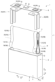
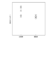
- FIG. 1 is a perspective view schematically showing an example of a battery according to an embodiment.
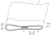
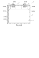
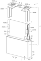
- FIG. 2 is a perspective view schematically showing the configuration of the electrode group in FIG. 1.
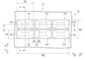
- FIG. 3 is a schematic diagram showing the configuration of the current collecting tab of the electrode group in FIG. 1.
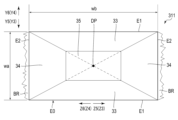
- FIG. 4 is a schematic diagram showing an example of a concave portion of a current collecting tab formed in the electrode group of FIG. 1.
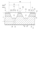
- FIG. 5 is a cross-sectional view schematically showing a cross section taken along the line VV in FIG. 3.
- FIG. 6 is a cross-sectional view schematically showing a cross section taken along the line VI-VI in FIG.
- FIG. 7 is a diagram showing the bonding strength when forming the recessed portion according to the embodiment.
- FIG. 1 is a perspective view schematically showing an example of a battery according to an embodiment.
- FIG. 2 is a perspective view schematically showing the configuration of the electrode group in FIG. 1.
- FIG. 3 is a schematic diagram showing the
- FIG. 8 is a diagram showing the bonding time when forming the recessed portion according to the embodiment.
- FIG. 9 is a diagram showing the bonding energy when forming the recessed portion according to the embodiment.
- FIG. 10 is a cross-sectional view schematically showing a battery according to a modification of the embodiment in a cross section perpendicular to the depth direction of the battery.
- FIG. 11 is a perspective view schematically showing an example of a battery according to another modification of the embodiment.
- FIG. 12 is a cross-sectional view schematically showing a joint portion of a battery according to another modification example shown in FIG. 11 in a cross section perpendicular to the first direction.
- FIG. 12 is a cross-sectional view schematically showing the joint portion of the battery according to another modification example shown in FIG. 11 in a cross section perpendicular to the second direction.
- FIG. 1 shows a battery 1 according to an embodiment.
- the battery 1 includes an electrode group 2 and an exterior member 3.
- the exterior member 3 includes an exterior container 5 and a lid member 6.
- the outer container 5 and the lid member 6 are each made of metal such as aluminum, aluminum alloy, iron, copper, or stainless steel.
- the depth direction (direction shown by arrows X1 and arrow ), and a height direction (direction indicated by arrow Z1 and arrow Z2) that intersects (orthogonal or substantially orthogonal to) both the depth direction and the lateral direction.
- the dimension in the depth direction is smaller than the dimension in the lateral direction and the dimension in the height direction.
- FIG. 1 is an exploded perspective view showing each member.
- the outer container 5 includes a bottom wall 7 and a peripheral wall 8.
- An internal cavity 10 in which the electrode group 2 is housed is defined by a bottom wall 7 and a peripheral wall 8 .
- the internal cavity 10 opens toward the side opposite to the side where the bottom wall 7 is located in the height direction.
- the lid member 6 is attached to the peripheral wall 8 at an end opposite to the bottom wall 7. Therefore, the lid member 6 closes the opening of the internal cavity 10 of the outer container 5.
- the lid member 6 and the bottom wall 7 face each other across the internal cavity 10 in the height direction.
- the electrode group 2 includes a pair of electrodes 13, a pair of current collectors 14, and a pair of current collector tabs 15.
- One of the pair of electrodes 13 is a positive electrode 13A, and the other of the pair of electrodes 13 is a negative electrode 13B.
- One of the pair of current collectors 14 is a positive electrode current collector 14A, and the other one of the pair of current collectors 14 is a negative electrode current collector 14B.
- One of the pair of current collector tabs 15 is a positive electrode current collector tab 15A, and the other one of the pair of current collector tabs 15 is a negative electrode current collector tab 15B.
- a separator (not shown) is interposed between the positive electrode 13A and the negative electrode 13B.
- the separator is made of an electrically insulating material and electrically insulates the positive electrode 13A from the negative electrode 13B.
- the positive electrode current collector 14A is formed from a positive electrode current collector foil or the like.
- a positive electrode active material-containing layer (not shown) is formed on the surface of the positive electrode current collector 14A.
- the positive electrode current collector 14A is, for example, aluminum foil or aluminum alloy foil.
- the thickness of the positive electrode current collector 14A is approximately 10 ⁇ m to 20 ⁇ m.
- the positive electrode active material-containing layer includes a positive electrode active material.
- the positive electrode active material-containing layer may optionally contain a binder and a conductive agent.
- the positive electrode active material is, for example, an oxide, a sulfide, a polymer, etc. that can intercalate and deintercalate lithium ions.
- the positive electrode current collector tab 15A is a portion of the positive electrode current collector 14A on which the positive electrode active material-containing layer is not supported (unsupported). The positive electrode current collector tab 15A protrudes from the negative electrode 13B and the separator.
- the negative electrode current collector 14B is formed from a negative electrode current collector foil or the like.
- a negative electrode active material containing layer (not shown) is formed on the surface of the negative electrode current collector 14B.
- the negative electrode current collector 14B is, for example, aluminum foil, aluminum alloy foil, copper foil, or the like.
- the thickness of the negative electrode current collector 14B is approximately 10 ⁇ m to 20 ⁇ m.
- the negative electrode active material-containing layer includes a negative electrode active material.
- the negative electrode active material-containing layer may optionally contain a binder and a conductive agent. Examples of the negative electrode active material include metal oxides, metal sulfides, metal nitrides, and carbon materials that can intercalate and deintercalate lithium ions.
- the negative electrode current collector tab 15B is a portion of the negative electrode current collector 14B on which the negative electrode active material-containing layer is not supported (unsupported).
- the negative electrode current collector tab 15B protrudes toward the side opposite to the side from which the positive electrode current collector tab 15A protrudes with respect to the positive electrode 13A and the separator.
- the positive electrode 13A, the negative electrode 13B, and the separator are wound around the winding axis W.
- the positive electrode 13A is provided shifted to one side in the axial direction along the winding axis W with respect to the separator.
- the negative electrode 13B is provided axially offset from the positive electrode 13A with respect to the separator. Therefore, the pair of current collecting tabs 15 (the positive current collecting tab 15A and the negative current collecting tab 15B) protrude outward in the axial direction with respect to the separator.
- the positive electrode current collector tab 15A protrudes toward one side in the axial direction with respect to the separator.
- the negative electrode current collector tab 15B protrudes toward the opposite side of the separator from the direction in which the positive electrode current collector tab 15A protrudes.
- a plurality of positive electrodes 13A and a plurality of negative electrodes 13B are alternately stacked. That is, the electrode group 2 has a stacked structure.
- the plurality of positive electrodes 13A are provided shifted to one side with respect to the separator.
- the plurality of negative electrodes 13B are provided offset from the positive electrode 13A with respect to the separator. Therefore, the pair of current collecting tabs 15 protrude outward with respect to the separator.
- the positive electrode current collecting tab 15A protrudes from the separator along the lateral direction of the battery 1
- the negative electrode current collecting tab 15B protrudes from the separator in the lateral direction of the battery 1 on the opposite side of the positive electrode current collecting tab 15A. stand out.
- the electrode group 2 will be explained as being the above-mentioned wound type electrode group, but the electrode group 2 is not limited to this.
- one of the pair of current collecting tabs 15 protrudes toward one side of the battery 1 in the lateral direction (axial direction along the winding axis W).
- the other of the pair of current collector tabs 15 protrudes toward the side opposite to the direction in which one of the pair of current collector tabs 15 protrudes in the lateral direction of the battery 1 . That is, the positive electrode current collector tab 15A protrudes to one side of the battery 1 in the lateral direction, and the negative electrode current collector tab 15B protrudes to the other side of the battery 1 in the lateral direction.
- the electrode group 2 is held (impregnated) with an electrolytic solution (not shown).
- the electrolyte may be a non-aqueous electrolyte in which an electrolyte is dissolved in an organic solvent, or may be an aqueous electrolyte such as an aqueous solution.
- a gel electrolyte or a solid electrolyte may be used.
- the solid electrolyte is interposed between the positive electrode 13A and the negative electrode 13B instead of a separator. In this case, the positive electrode 13A is electrically insulated from the negative electrode 13B by the solid electrolyte.
- a pair of electrode terminals 16 are attached to the outer surface of the lid member 6. A pair of electrode terminals 16 are exposed to the outside of the battery 1 and arranged on the outer surface of the lid member 6. Therefore, the pair of electrode terminals 16 are installed on the exterior member 3.
- the pair of electrode terminals 16 is made of a conductive material such as metal.
- One of the pair of electrode terminals 16 is the positive terminal 16A of the battery 1.
- One of the pair of electrode terminals 16 other than the positive terminal 16A is the negative terminal 16B of the battery 1.
- An insulating member 18 is provided on the outer surface of the lid member 6 between each of the pair of electrode terminals 16 and the lid member 6. Each of the pair of electrode terminals 16 is electrically insulated from the outer container 5 and the lid member 6 by the insulating member 18 .
- a pair of conductive members 20 are arranged in the internal cavity 10 of the outer container 5.
- One of the pair of conductive members 20 is the positive conductive member 20A.
- One of the pair of conductive members 20 other than the positive conductive member 20A is the negative conductive member 20B.
- the positive conductive member 20A forms at least a portion of the electrical path between the positive current collector tab 15A and the positive terminal 16A. Therefore, the positive electrode current collecting tab 15A is electrically connected to the positive electrode terminal 16A through at least the positive electrode conductive member 20A.
- Negative conductive member 20B forms at least a portion of the electrical path between negative electrode current collector tab 15B and negative electrode terminal 16B.
- the negative electrode current collecting tab 15B is electrically connected to the negative electrode terminal 16B through at least the negative electrode conductive member 20B.
- Each of the conductive members 20 is formed from a conductive material such as metal.
- the conductive material forming the conductive member 20 is, for example, aluminum, stainless steel, copper, iron, or the like.
- the pair of conductive members 20 are, for example, a pair of leads.
- each of the pair of current collecting tabs 15 a plurality of strips are stacked.
- a plurality of strips are tied together in each of the pair of current collecting tabs 15. Therefore, in each of the current collecting tabs 15 , a plurality of bundled band-shaped portions are electrically connected to corresponding one of the pair of electrode terminals 16 via the corresponding one of the pair of conductive members 20 .
- a plurality of band-shaped portions of the positive electrode current collecting tab 15A are electrically connected to the positive electrode terminal 16A via the positive electrode conductive member 20A.
- each of the pair of conductive members 20 includes a pair of leg portions and is formed in a bifurcated shape.
- each of the electrically conductive members 20 at least one of the pair of legs is connected to a plurality of tied band-shaped parts of the corresponding one of the current collecting tabs 15.
- each of the conductive members 20 may be provided with only one leg. In this case, in each of the conductive members 20, only one leg portion is connected to a plurality of band-shaped portions of the corresponding one of the current collection tabs 15, which are tied together.
- the lid member 6 is formed with a gas release valve 23 and a liquid injection port (not shown). Then, a sealing plate 25 that closes the liquid injection port is welded to the outer surface of the lid member 6. Note that the gas release valve 23, the liquid injection port, and the like do not need to be provided in the battery 1. Furthermore, in the internal cavity 10 of the outer container 5, the current collecting tabs (15A and 15B) and the pair of conductive members 20 are electrically insulated from the outer container 5 by one or more insulating members (not shown). Ru.
- a positive electrode side joint portion 31A is formed on the positive electrode current collector tab 15A
- a negative electrode side joint portion 31B is formed on the negative electrode current collector tab 15B.
- the positive electrode side joint portion 31A is configured similarly to the negative electrode side joint portion 31B. Therefore, the same configuration explanation as that for the positive electrode side joint portion 31A also holds true for the negative electrode side joint portion 31B.
- the positive electrode current collecting tab 15A will be described as the current collecting tab 15
- the positive electrode side joint portion 31A will be described as the joint portion 31
- the description of the negative electrode current collecting tab 15B and the negative electrode side joint portion 31B will be omitted.
- the joint portion 31 does not need to be formed on both of the pair of current collecting tabs 15. That is, the joint portion 31 may be formed on only one of the pair of current collecting tabs 15, or may be formed on both of the pair of current collecting tabs 15.
- FIG. 2 is a schematic diagram showing a part of the electrode group 2 housed in the battery 1 according to the embodiment.
- the height direction, lateral direction, and depth direction of the battery 1 are defined similarly to FIG. 1.
- the first direction (indicated by arrows Z3 and Z4) coincides or substantially coincides with the height direction of the battery 1.
- the second direction (indicated by arrows Y3 and Y4) intersects (orthogonally or approximately orthogonally) the first direction.
- the third direction (indicated by arrows X3 and X4) intersects (orthogonally or approximately orthogonally) both the first direction and the second direction.
- the second direction coincides or substantially coincides with the lateral direction of the battery 1.
- the third direction matches or substantially matches the depth direction of the battery 1.
- the third direction is the depth direction of the joint portion 31.
- the joint portion 31 is formed, for example, at a connection portion between a conductive member (not shown in FIG. 2) and the current collection tab 15. Thereby, the current collecting tab 15 is joined to the electrically conductive member, and the current collecting tab 15 and the electrically conductive member are electrically connected.
- the bonding portion 31 is formed by, for example, a horn used in ultrasonic bonding (ultrasonic horn).
- the electrode group 2 of this embodiment is a wound type electrode group as described above. Therefore, the ultrasonic horn is placed at an appropriate position on the current collecting tab 15 from the outside of the battery 1 in the lateral direction. The ultrasonic horn presses the current collecting tab 15 against the conductive member and deforms the current collecting tab 15.
- the ultrasonic horn forms the joint portion 31 by recessing the current collecting tab 15 toward the conductive member side in the depth direction of the battery 1 and applying ultrasonic vibration.
- the joint portion 31 is preferably formed from the current collecting tab 15 to the conductive member along the depth direction of the battery 1 (the depth direction of the joint portion 31). As a result, the joint portion 31 is formed across both the current collecting tab 15 and the conductive member in the depth direction, so the joint strength between the current collecting tab 15 and the conductive member is increased, and therefore the joint between the current collecting tab 15 and the conductive member It is possible to reduce the occurrence of malfunctions of the battery 1 due to malfunction.
- FIG. 3 is an enlarged schematic diagram showing the joint portion 31 formed on the current collecting tab 15.
- the joint portion 31 of this embodiment includes a plurality of recesses and a separation portion 32 formed between the plurality of recesses.
- the joint portion 31 of this embodiment includes six recesses 311 to 316.
- the six recesses 311 to 316 are formed close to each other. Specifically, a plurality of recesses lined up along the first direction of the joint part 31 are formed in the joint part 31, and a plurality of recesses lined up along the second direction of the joint part 31 are formed. It is formed.
- the joint portion 31 includes a plurality of recesses lined up along at least one of the first direction and the second direction of the joint portion 31.
- the recesses 311 to 316 are also referred to as a first recess to a sixth recess, respectively.
- the first recess 311 and the second recess 312, the third recess 313 and the fourth recess 314, the fifth recess 315 and the sixth recess 316 are located in the joint portion 31, respectively. are arranged along the second direction and are formed adjacent to each other. Further, the first recess 311 , the third recess 313 , and the recess 315 are formed side by side along the first direction of the joint 31 , and the first recess 311 , the third recess 313 , and the third recess 313 and a fifth recess 315 are formed adjacent to each other.
- a second recess 312, a fourth recess 314, and a sixth recess 316 are formed in line along the first direction of the joint 31, and the second recess 312, fourth recess 314, and sixth recess 316
- a fourth recess 314 and a sixth recess 316 are formed adjacent to each other.
- three recesses are formed side by side in the first direction of the joint part 31, and two recesses are formed side by side in the second direction of the joint part 31.
- Six recesses are formed adjacent to each other.
- the spacing section 32 includes a first spacing section 321 and a second spacing section 322.
- the first separation portion 321 is formed between two adjacent recesses along the first direction of the joint portion 31 .
- the first spacing section 321 includes the first recess 311 and the third recess 313, the third recess 313 and the fifth recess 315, the second recess 312 and the fourth recess 314, and the third recess 313 and the fifth recess 315.
- the fourth recess 314 and the sixth recess 316 are respectively formed between the fourth recess 314 and the sixth recess 316 .
- the second spacing portion 322 is formed between two adjacent recesses along the second direction of the joint portion 31 . Specifically, they are formed between the first recess 311 and the second recess 312, the third recess 313 and the fourth recess 314, and the fifth recess 315 and the sixth recess 316, respectively.
- the first spaced part 321 between the first recess 311 and the third recess 313 and the first spaced part 321 between the second recess 312 and the fourth recess 314 are No deviation or almost no deviation in direction 1.
- the first separation part 321 between the third recess 313 and the fifth recess 315 and the first separation part 321 between the fourth recess 314 and the sixth recess 316 are the joint part. No deviation or almost no deviation in the first direction of 31.
- a second spaced part 322 between the first recessed part 311 and the second recessed part 312, a second spaced part 322 between the third recessed part 313 and the fourth recessed part 314, a fifth recessed part 315, and The second spacing portions 322 between the sixth recesses 316 are not offset or hardly offset relative to each other in the first direction of the joint portion 31 . Therefore, in the joining part 31, the plurality of first separating parts 321 form a linear or substantially linear separating part along the second direction of the joining part 31, and the plurality of second separating parts 322 form a joining part.
- a linear or substantially linear spaced apart portion is formed along the first direction of the portion 31 .
- FIG. 4 is a schematic diagram showing one of the plurality of recesses 311 to 316 formed in the current collecting tab 15.
- FIG. 5 is a cross-sectional view of the joint portion 31 shown in FIG. 3 taken along line VV.
- FIG. 6 is a cross-sectional view of the joint portion 31 shown in FIG. 3 taken along line VI-VI.
- the recesses 311 to 316 are similarly configured. Therefore, the same explanation of the configuration as for the recess 311 also holds true for the recesses 312 to 316. Note that in FIGS. 4 to 6 as well, a first direction, a second direction, and a third direction are defined similarly to FIGS. 2 and 3.
- the recess 311 includes two pairs of edges E1 and E2, two pairs of inclined surfaces 33 and 34, and a bottom 35.
- the two pairs of edges E1 and E2 include a pair of edges E1 and a pair of edges E2.
- the pair of edges E1 are located apart from each other in the second direction of the joint 31.
- One of the pair of edges E1 forms one edge of the recess 311 in the second direction of the joint 31, and the other of the pair of edges E1 forms the other edge of the recess 311 in the second direction of the joint 31. form the edge of The pair of edges E1 extends along the first direction of the joint 31 between the pair of edges E2.
- the pair of edges E2 are located apart from each other in the first direction of the joint portion 31.
- One of the pair of edges E2 forms one edge of the recess 311 in the first direction of the joint 31, and the other of the pair of edges E2 forms the other edge of the recess 311 in the first direction of the joint 31.
- form the edge of The pair of edges E2 extends along the second direction of the joint 31 between the pair of edges E1. Therefore, the peripheral edge E of the recess 311 is formed by the two pairs of edges E1 and E2.
- the two pairs of inclined surfaces 33 and 34 are arranged adjacent to each other.
- Each of the pair of inclined surfaces 33 is formed from the edge E1 forming the end of the inclined surface 33 to the bottom 35 in the second direction of the joint portion 31.
- Each of the ends E3 of the pair of inclined surfaces 33 is formed toward the bottom 35 side with respect to the edge E1 in the second direction as it goes toward the center of the joint portion 31 in the first direction.
- the pair of inclined surfaces 33 move toward one side of the joint portion 31 in the third direction, that is, toward the side of the joint portion 31 where the conductive member 20 is located in the third direction (the depth direction of the battery 1). formed into a state.
- Each of the pair of inclined surfaces 34 is formed from the edge E2 forming the end of the inclined surface 34 to the bottom 35 in the first direction of the joint portion 31.
- Each of the ends E3 of the pair of inclined surfaces 34 is formed toward the bottom 35 side with respect to the edge E2 in the second direction as it goes toward the center of the joint portion 31 in the second direction.
- the pair of inclined surfaces 34 move toward one side of the joint portion 31 in the third direction, that is, toward the side of the joint portion 31 where the conductive member 20 is located in the third direction (the depth direction of the battery 1). formed into a state.
- the two pairs of inclined surfaces 33 and 34 surround the bottom portion 35 from the outer peripheral side.
- the extension surfaces of the two pairs of inclined surfaces 33 and 34 intersect at an intersection DP.
- the pair of inclined surfaces 33 have the same or substantially the same shape
- the pair of inclined surfaces 34 have the same or substantially the same shape.
- the pair of inclined surfaces 33 and the pair of inclined surfaces 34 each have a triangular shape or a substantially triangular shape.
- a plurality of intersection points DP may be formed in the recess 311. That is, the extension surfaces of the pair of inclined surfaces 33 and the extension surfaces of the pair of inclined surfaces 34 may intersect at multiple points.
- the dimension between both ends of the recess 311 in the second direction of the joint 31 is wa, and the dimension between both ends of the recess 311 in the first direction of the joint 31 is wa.
- the dimension wa is smaller than the dimension wb. That is, wa ⁇ wb. Therefore, the recess 311 is formed in a rectangular or substantially rectangular shape that is elongated in the first direction of the joint 31 when viewed from one of the third directions of the joint 31 .
- the dimension wa matches or substantially matches the length of the pair of edges E2
- the dimension wb matches or substantially matches the length of the pair of edges E1.
- the dimension wa is 0.2 times or more and 0.8 times or less with respect to the dimension wb.
- the shape of the recess 311 is not limited to the shape shown in FIGS. 3 and 4.
- the shape of the recess 311 may be any shape as long as it satisfies the condition that the dimension wa is smaller than the dimension wb.
- the shape of the recess 311 may be elliptical, triangular, or trapezoidal.
- the shape of the recess 311 may be a truncated cone, a truncated triangular pyramid, or a truncated quadrangular pyramid.
- dimension wa is smaller than dimension wb.
- the dimension wa is the same or approximately the same in all of the recesses 311 to 316, and the dimension wb is the same or approximately the same in any of the recesses 311 to 316. are also the same or substantially the same.
- a plurality of the recesses 311 to 316 are formed in a row in the second direction of the joint portion 31, and a plurality of recesses are formed in a row in the first direction of the joint portion 31.
- the dimension between both ends of the joint 31 in the second direction of the joint 31 is WA
- the dimension of the joint 31 in the first direction of the joint 31 is WA.
- the dimension between both ends be WB.
- dimension WA is smaller than dimension WB. That is, WA ⁇ WB.
- the dimension WA is 0.5 mm or more and 5.0 mm or less.
- the dimension WA of the joint portion 31 in the second direction is larger than twice the dimension wa of each of the recesses 311 to 316 in the second direction. That is, WA>2 ⁇ wa.
- three recesses 311 to 316 are formed in line in the first direction of the joint portion 31. Therefore, the dimension WB of the joint portion 31 in the first direction is larger than three times the dimension wb of each of the recesses 311 to 316 along the first direction. That is, WB>3 ⁇ wb.
- the dimension of the first separation portion 321 along the first direction is (WB-3 ⁇ wb)/2, which is half the difference between WB and three times wb.
- the dimension of the second spacing portion 322 along the second direction is the difference between WA and twice wa, which is WA-2 ⁇ wa. Note that the dimensions of the first spacing portions 321 along the first direction may not be the same for the plurality of first spacing portions 321 . However, in the plurality of first separation parts 321 arranged in the first direction of the joint part 31, the total dimension of the joint part 31 along the first direction is WB-3 ⁇ wb.
- the sum of the dimensions along the first direction of both the first separation part 321 between the recess 311 and the recess 313 and the first separation part 321 between the recess 313 and the recess 315 is WB-3 ⁇ wb.
- the sum of the dimensions along the first direction of both the first separation part 321 between the recess 312 and the recess 314 and the first separation part 321 between the recess 314 and the recess 316 is WB-3 ⁇ wb.
- the joint 31 includes m ⁇ n recesses. Also at this time, WA ⁇ WB is satisfied in the joint portion 31.
- the WA of the joint 31 is larger than m times the wa of the recess, and the WB of the joint 31 is n times larger than the wb of the recess. That is, WA>m ⁇ wa and WB>n ⁇ wb.
- the dimension of the first separation part 321 along the first direction is 1/(n-1) of the difference between the WB of the joint part 31 and n times the wb of the recessed part, that is, (WB-n ⁇ wb) /(n-1).
- the dimension along the second direction of the second separation part 322 is 1/(m-1) of the difference between the WA of the joint part 31 and m times the wa of the recessed part, that is, (WA-m ⁇ wa) /(m-1).
- the first spacing is WB-n ⁇ wb
- the first spacing is WB-n ⁇ wb
- the first spacing is WB-n ⁇ wb
- the first spacing is WB-n ⁇ wb
- the first spacing is WB-n ⁇ wb
- the second spacing is The dimensions of each portion 322 are not particularly limited.
- the dimension between both ends in the second direction is smaller than the dimension between both ends in the first direction.
- the dimensions between the ends of each of the plurality of recesses in the second direction are wa1, wa2, ..., wan, and the dimensions between the ends of each of the plurality of recesses in the first direction are wb1, wb2. ,..., wbm, then WA>wa1+wa2+...+wan and WB>wb1+wb2+...+wbm.
- the current collecting tab 15 includes a surface S1 and a surface S2.
- the surface S1 faces the side where the conductive member 20 is located in the third direction of the joint portion 31.
- the surface S2 faces the opposite side to the surface S1 (opposite to the conductive member 20 side) in the third direction of the joint portion 31. Then, the surface S1 of the current collecting tab 15 comes into contact with the conductive member 20.
- a pair of inclined surfaces 33 are inclined with respect to the surface S1 and inclined with respect to the surface S2. The pair of inclined surfaces 33 are formed beyond the surface S1 of the current collecting tab 15 in the third direction of the joint portion 31.
- a pair of inclined surfaces 33 are formed extending from the current collecting tab 15 to the conductive member 20. That is, the pair of inclined surfaces 33 are formed from the surface S2 of the current collecting tab 15 to the inside of the conductive member 20. Further, as shown in FIG. 6, in the recess 311, a pair of inclined surfaces 34 are inclined with respect to the surface S1 and inclined with respect to the surface S2. The pair of inclined surfaces 34 are formed beyond the surface S1 of the current collecting tab 15 in the third direction of the joint portion 31. A pair of inclined surfaces 34 are formed extending from the current collecting tab 15 to the conductive member 20. That is, the pair of inclined surfaces 34 are formed from the surface S ⁇ b>2 of the current collecting tab 15 to the inside of the conductive member 20 .
- the intersection DP is located inside the conductive member 20 in the third direction of the joint portion 31. That is, the intersection DP is formed on the side where the conductive member 20 is located relative to the surface S1 in the third direction of the joint portion 31.
- the recess distance d of the recess 311 along the third direction is a virtual distance from the surface S2 of the current collecting tab 15 to the intersection DP.
- the recess distance d of the recess 311 is the thickness of the current collecting tab 15 (i.e., from the surface S1 to the surface S2). (dimension along the third direction of the joint portion 31).
- the intersection point DP is not located beyond the conductive member 20 in the third direction. Therefore, the recess distance d of the recess 311 is smaller than the total thickness of the current collecting tab 15 and the conductive member 20 .
- the recess distance d of the recess 311 is larger than half of the wa of the recess 311. Regarding the recess distance d, it is preferable that d>wa/2. Further, since the pair of inclined surfaces 33 are formed in the same or substantially the same shape as described above, the intersection DP is located at the center of the recess 311 in the second direction of the joint 31 . Therefore, the recessed portion 311 is formed symmetrically with respect to a plane that is perpendicular or substantially perpendicular to the second direction passing through the intersection DP. Therefore, as shown in FIG. 5, it is preferable that the angle ⁇ 1 between the pair of inclined surfaces 33 is an acute angle.
- the angle ⁇ 1 between the pair of inclined surfaces 33 is smaller than 45°.
- the angle ⁇ 1 between the pair of inclined surfaces 33 is preferably larger than 30°. That is, it is more preferable that the angle ⁇ 1 between the pair of inclined surfaces 33 is larger than 30° and smaller than 45°.
- the recess distance d in the recess 311 is the distance from the surface S2 of the current collecting tab 15 to the intersection DP. Since the pair of inclined surfaces 34 are formed to have the same or substantially the same shape as described above, the intersection DP is located at the center of the recess 311 in the first direction of the joint 31 . Therefore, the recessed portion 311 is formed symmetrically with respect to a plane that is perpendicular or substantially perpendicular to the first direction passing through the intersection DP. At this time, the angle ⁇ 2 between the pair of inclined surfaces 34 is not particularly limited.
- the angle ⁇ 2 between the pair of inclined surfaces 34 is determined on the condition that both wb is larger than wa and the angle ⁇ 1 between the pair of inclined surfaces 33 is an acute angle. Therefore, the angle ⁇ 2 between the pair of inclined surfaces 34 is preferably larger than the angle ⁇ 1 between the pair of inclined surfaces 33. Furthermore, it is more preferable that the angle ⁇ 2 between the pair of inclined surfaces 34 is an obtuse angle.
- a recess distance d is defined for each recess. That is, in each recess, the recess distance d is preferably larger than half the dimension between both ends of the recess in the second direction.
- a burr BR is formed on the peripheral edge E of the recess 311.
- the burr BR is formed when the current collecting tab 15 is dented by an ultrasonic horn.
- the ultrasonic horn forms the recess 311 by being pressed against the current collecting tab 15 while vibrating in the first direction of the joint 31 .
- the current collecting tab 15 is pushed by the ultrasonic horn toward the side where the conductive member 20 is located, and vibration along the first direction of the joint portion 31 is applied to the current collecting tab 15. Therefore, the ultrasonic horn that vibrates along the extending direction of the pair of edges E1 forms the pair of edges E1 on the current collecting tab 15.
- an ultrasonic horn that vibrates in a direction intersecting (perpendicular or substantially perpendicular to) the pair of edges E2 formed on the current collector tab 15 forms the pair of edges E2 on the current collector tab 15. Therefore, there is a difference in the amount of burr BR remaining between the pair of edges E1 and the pair of edges E2.
- the amount of burrs remaining is larger in the region adjacent to the recess 311 from the first direction than in the region adjacent to the recess 311 from the second direction.
- the region adjacent to the recess 311 from the first direction is, for example, a region adjacent to the pair of edges E2 from the first direction.
- the region adjacent to the recess 311 from the second direction is, for example, a region adjacent to the pair of edges E1 from the second direction.
- burr BR formed on the pair of edges E1 is not shown in FIGS. 4 and 5. Further, the burr BR does not need to be formed over the entire length of the pair of edges E2. That is, the burr BR may be formed only on a part of the pair of edges E2. In the recesses 312 to 316, similarly to the recess 311, burrs BR are formed on the peripheral edge E, and the remaining amount of burr BR formed on the pair of edges E2 is larger than that of the pair of edges E1. Therefore, in the joint portion 31 of the present embodiment, the dimension of the edge where a large amount of burrs BR remains is smaller than the dimension of the edge where a small amount of burrs BR remains.
- burrs BR are formed on the peripheral edges E of the recesses 311 to 316.
- the recesses 311 to 316 are formed by ultrasonic horns that vibrate in the vibration direction along the first direction of the joint 31.
- the burr BR formed on the outermost edge E2 (referred to as the outermost edge EO) of the joint 31 in the first direction is The remaining amount is large compared to the other edges E1 and E2. It is presumed that the cause of this difference in the amount of burrs remaining is that the burrs formed on the edges other than the outermost edge EO are peeled off by the pressure and vibration on the current collecting tab 15. Ru.
- the edge E2 located on the outside of the joint portion 31 in the first direction is the outermost edge EO.
- the edge E2 located on the outside of the joint 31 in the first direction is the outermost edge EO.
- the edge E2 located on the outside of the joint 31 in the first direction is the outermost edge EO.
- the edge E2 located on the outside of the joint 31 in the first direction is the outermost edge EO.
- the joint portion 31 connects the current collection tab 15 and the conductive member 20.
- the joint portion 31 includes a recess and a peripheral portion E.
- the concave portion is recessed toward the side where the conductive member 20 is located in the current collecting tab 15, and has a second dimension wa between both ends in the second direction that is smaller than a first dimension wb between the two ends in the first direction.
- the peripheral portion E is a portion surrounding the recess and adjacent to the recess from the first direction, and has a larger amount of residual burrs than a portion adjacent to the recess from the second direction.
- the joint part 31 By forming the joint part 31 in this way, when the joint part 31 is formed using an ultrasonic horn vibrating in the first direction, the part where more burr BR remains than other parts can be removed. Can be made smaller in size. Therefore, the total amount of burrs generated when forming the joint portion 31 can be reduced.
- the joint portion 31 is formed extending from the current collecting tab 15 to the conductive member 20.
- the joint portions 31 are formed on both sides of the surface S1. Thereby, the current collecting tab 15 and the conductive member 20 can be sufficiently joined.
- the joint portion 31 includes a plurality of recesses, and each of the plurality of recesses has one peripheral edge.
- the fourth dimension WA between the two ends in the second direction is smaller than the third dimension WB between the two ends in the first direction. .
- the amount of burrs remaining is larger at the outermost portion of the joint portion 31 in the first direction among the peripheries of the plurality of recesses than at other portions.
- the second dimension wa is 0.2 times or more and 0.8 times or less the first dimension wb.
- the recess 311 By forming the recess 311 with such dimensions, the recess 311 in the direction intersecting (perpendicular or substantially perpendicular to) the vibration direction during joining using the ultrasonic horn vibrating along the first direction of the joining part 31. Dimensions can be reduced.
- the second dimension wa is 0.2 times or more the first dimension wb, the possibility of cutting the current collecting tab 15 to be welded decreases because the second dimension wa is not too small. .
- the second dimension wa is 0.8 times or less than the first dimension wb, a sufficient dimensional difference between the first direction and the second direction can be ensured, so that the effects of this embodiment can be sufficiently obtained. Obtainable.
- the recess distance d of the recess is preferably larger than half of the second dimension wa.
- the joint portion 31 having the recessed portion of the embodiment was formed by ultrasonically bonding the current collecting tab 15 and the conductive member 20 using an ultrasonic horn.
- the current collecting tab 15 and the conductive member 20 were ultrasonically bonded using an ultrasonic horn by forming a bonding portion 31 having a concave portion having the same dimensions as the edges E1 and E2.
- the number of recesses is one row in the second direction of the joint portion 31 and three rows in the first direction of the joint portion 31. Therefore, in each of the Examples and Comparative Examples, a total of three recesses were formed at once.
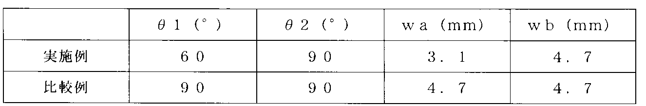
- the vibration direction of the ultrasonic horn was made to substantially match the first direction of the joint 31. Further, in both the Examples and Comparative Examples, the test was performed five times. The values of ⁇ 1, ⁇ 2, wa, and wb in each recess were set as shown in the table below.
- the results are shown in FIGS. 7 to 9.
- the vertical axis in FIG. 7 shows bonding strength
- the vertical axis in FIG. 8 shows bonding time
- the vertical axis in FIG. 9 shows bonding energy.
- the units of the vertical axes in FIGS. 7 to 9 are arbitrary units corresponding to each item.
- the bonding strength of the recessed portions of the example has smaller variations than the bonding strength of the recessed portions of the comparative example.
- the bonding time of the recessed portions of the example has smaller variations than the bonding time of the recessed portions of the comparative example.
- the bonding energy of the recessed portions of the example has smaller variations than the bonding energy of the recessed portions of the comparative example.
- the bottom 35 of at least one of the recesses 311 to 316 may be formed at the same position as the intersection DP in the third direction. In this case, the bottom 35 coincides or substantially coincides with the intersection DP. Also in this modification, the two pairs of inclined surfaces 33 and 34 have the same configuration as in the above-described embodiment. Therefore, in this modification, the intersection DP becomes the bottom 35, and the shape of the recess is, for example, a triangular pyramid, a quadrangular pyramid, or a cone. Further, the recess distance d is the depth of the recess.
- FIG. 10 is a cross-sectional view schematically showing a modification of the battery 1 according to the embodiment in a cross section perpendicular to the depth direction of the battery 1.
- the height direction, lateral direction, and depth direction of the battery 1 are defined.
- the first direction (indicated by arrows Y5 and Y6) coincides or substantially coincides with the lateral direction of the battery 1.
- the second direction (indicated by arrow Z5 and arrow Z6) coincides or substantially coincides with the height direction of battery 1.
- the third direction matches or substantially matches the depth direction of the battery 1.
- the pair of current collecting tabs 15 protrude toward the same side relative to each other.
- the pair of current collecting tabs 15 protrude from the electrode group 2 on the side where the pair of electrode terminals 16 are located in the height direction of the battery 1 .
- the pair of current collecting tabs 15 do not come into contact with each other.
- the positive electrode current collector tab 15A protrudes from the electrode group 2 on the side where the positive electrode terminal 16A is located.
- the negative electrode current collector tab 15B protrudes from the electrode group 2 on the side where the negative electrode terminal 16B is located. In this case as well, as shown in FIG.
- the peripheral edge E surrounds the recess and is a region adjacent to the recess from the first direction and a region adjacent to the recess from the second direction. There is a large amount of burr remaining compared to the area adjacent to the area. Thereby, the battery 1 of this modification also has the same effects as the above-described embodiments.
- the exterior member of the battery 1 is not limited to the configuration formed from the exterior container 5 and the lid member 6.
- the exterior part may be formed from a first exterior member and a second exterior member made of metal, as in Reference Document 1 (International Publication No. 2016/204147).
- the first exterior member includes a bottom wall and a peripheral wall, and in the first exterior member, a flange protrudes toward the outer peripheral side from an end of the peripheral wall opposite to the bottom wall. Then, the second exterior member is attached to the flange of the first exterior member.
- the exterior of the battery may be formed from a three-layer laminate film in which a metal layer is sandwiched between resin layers.
- the joint portion 31 is formed on the current collecting tab 15 in the same manner as in any of the above-described embodiments.
- FIG. 11 is a perspective view schematically showing an example of a battery according to a modification of the embodiment.
- the height direction, lateral direction, and depth direction of the battery 1, and the first direction, second direction, and third direction of the joint portion 31 are defined.
- FIG. 12 is a cross-sectional view of the joint portion 31 shown in FIG. 11 in a cross section perpendicular or substantially perpendicular to the first direction.
- FIG. 13 is a sectional view showing the joint portion 31 shown in FIG. 11 in a cross section perpendicular or substantially perpendicular to the second direction. 12 and 13, similarly to FIG. 11, the height direction, lateral direction, and depth direction of the battery 1, and the first direction, second direction, and third direction of the joint portion 31 are stipulated.
- the conductive member 20 is formed from a plurality of members.
- a backup lead 21 as a member of the conductive member 20 is attached to the current collecting tab 15.
- the positive electrode side backup lead 21A is attached to the positive electrode current collecting tab 15A
- the negative electrode side backup lead 21B is attached to the negative electrode current collecting tab 15B.
- the backup lead 21 includes a surface S3.
- the surface S3 faces the opposite side to the surface S1 (opposite to the current collecting tab 15 side) in the third direction of the joint portion 31, and forms the surface of the joint portion 31.
- a pair of sloped surfaces 33 are formed from the surface S3 of the backup lead 21 to the inside of the conductive member 20, and a pair of sloped surfaces 34 are formed from the surface S3 of the backup lead 21 to the inside of the conductive member 20.
- the recess distance d is the distance from the surface S3 of the backup lead 21 to the intersection DP.
- the intersection DP may be located closer to the conductive member 20 than the surface S1 of the current collecting tab 15 in the third direction.
- the intersection point DP may be located on the side of the backup lead 21 that contacts the conductive member 20 in the third direction.
- the two pairs of inclined surfaces 33 and 34 are formed in the third direction from the backup lead 21 on the side that contacts the current collecting tab 15 to the vicinity of the backup lead 21 on the side that contacts the conductive member 20.
- the peripheral edge E surrounds the recess and is a region adjacent to the recess from the first direction, and has a lower burr than a region adjacent to the recess from the second direction. There is a large amount of residue.
- the battery 1 of this modification also has the same effects as the above-described embodiments.
- the joint that connects the current collecting tab of the battery and the conductive member includes a recess and a peripheral edge.
- the concave portion is recessed toward the side where the conductive member is located in the current collecting tab, and has a second dimension between both ends in the second direction that is smaller than a first dimension between both ends in the first direction.
- the peripheral portion is a portion surrounding the recess and adjacent to the recess from the first direction, and has a larger amount of burrs remaining than a portion adjacent to the recess from the second direction.
Abstract
実施形態の電池は、外装部材、電極端子、電極群、導電部材、及び接合部を備える。電極端子は、外装部材に設置される。電極群は、外装部材の内部空洞に収納され、突出する集電タブを備える。導電部材は、電極端子と集電タブとの間を電気的に接続する。接合部は、集電タブと導電部材とを接続する。接合部は、凹部及び周縁部を備える。凹部は、集電タブにおいて導電部材が位置する側へ凹み、第1の方向について両端の間の第1の寸法よりも第1の方向に交差する第2の方向について両端の間の第2の寸法が小さい。周縁部は、凹部を囲み、第1の方向から凹部に隣接する部位で、第2の方向から凹部に隣接する部位に比べて、バリの残留量が多い。
Description
本発明の実施形態は、電池及び電池の製造方法に関する。
リチウムイオン二次電池等の電池として、外装部材の内部空洞に、正極及び負極を備える電極群が収納されるものがある。この電池では、電極端子が、外装部材に設置される。また、電極群は、集電体及び集電体に担持される活物質含有層を備える。集電体は、活物質含有層が担持していない部分としての集電タブを備える。そして、集電タブは、リード等の導電材料を介して、電極端子に電気的に接続される。また、集電タブでは、複数の帯状部が積層される。
前述のような電池の製造時、集電タブの積層された複数の帯状部が、例えば、超音波接合により導電部材等と接合される。すなわち、集電タブの積層された複数の帯状部及び導電部材は、互いが変形することにより接合される。このようにして帯状部と導電部材とを接合すると、接続部分に凹部が形成されるとともに、凹部の周縁等にバリが形成されることがある。バリは、凹部が形成される過程で前述の周縁等に発生する突起や、帯状部等の残留部分である。このような接合では、帯状部と導電部材とを接合する凹部の周縁等にバリが形成することの低減が求められている。
本発明が解決しようとする課題は、帯状部と導電部材とを接合する凹部の周縁等にバリが形成されることを低減できる電池及び電池の製造方法を提供することである。
実施形態の電池は、外装部材、電極端子、電極群、導電部材、及び接合部を備える。電極端子は、外装部材に設置される。電極群は、外装部材の内部空洞に収納され、突出する集電タブを備える。導電部材は、電極端子と集電タブとの間を電気的に接続する。接合部は、集電タブと導電部材とを接続する。接合部は、凹部及び周縁部を備える。凹部は、集電タブにおいて導電部材が位置する側へ凹み、第1の方向について両端の間の第1の寸法よりも第1の方向に交差する第2の方向について両端の間の第2の寸法が小さい。周縁部は、凹部を囲み、第1の方向から凹部に隣接する部位で、第2の方向から凹部に隣接する部位に比べて、バリの残留量が多い。
以下、実施形態について図面を参照して説明する。
(実施形態)
図1は、実施形態に係る電池1を示す。図1に示すように、電池1は、電極群2及び外装部材3を備える。外装部材3は、外装容器5及び蓋部材6を備える。外装容器5及び蓋部材6のそれぞれは、アルミニウム、アルミニウム合金、鉄、銅又はステンレス等の金属から形成される。ここで、電池1(外装容器5)では、奥行き方向(矢印X1及び矢印X2で示す方向)、奥行き方向に対して交差する(直交又は略直交な)横方向(矢印Y1及び矢印Y2で示す方向)、及び、奥行き方向及び横方向の両方に対して交差する(直交又は略直交な)高さ方向(矢印Z1及び矢印Z2で示す方向)が、規定される。電池1及び外装容器5のそれぞれでは、奥行き方向についての寸法が、横方向についての寸法、及び、高さ方向についての寸法のそれぞれに比べて、小さい。なお、図1は、部材ごとに分解して示す斜視図である。
図1は、実施形態に係る電池1を示す。図1に示すように、電池1は、電極群2及び外装部材3を備える。外装部材3は、外装容器5及び蓋部材6を備える。外装容器5及び蓋部材6のそれぞれは、アルミニウム、アルミニウム合金、鉄、銅又はステンレス等の金属から形成される。ここで、電池1(外装容器5)では、奥行き方向(矢印X1及び矢印X2で示す方向)、奥行き方向に対して交差する(直交又は略直交な)横方向(矢印Y1及び矢印Y2で示す方向)、及び、奥行き方向及び横方向の両方に対して交差する(直交又は略直交な)高さ方向(矢印Z1及び矢印Z2で示す方向)が、規定される。電池1及び外装容器5のそれぞれでは、奥行き方向についての寸法が、横方向についての寸法、及び、高さ方向についての寸法のそれぞれに比べて、小さい。なお、図1は、部材ごとに分解して示す斜視図である。
外装容器5は、底壁7及び周壁8を備える。電極群2が収納される内部空洞10は、底壁7及び周壁8によって規定される。外装容器5では、内部空洞10は、高さ方向について、底壁7が位置する側とは反対側へ向かって開口する。蓋部材6は、底壁7とは反対側の端部で、周壁8に取り付けられる。このため、蓋部材6は、外装容器5の内部空洞10の開口を塞ぐ。蓋部材6及び底壁7は、高さ方向について内部空洞10を挟んで対向する。
電極群2は、一対の電極13、一対の集電体14、及び一対の集電タブ15を備える。一対の電極13の一方が正極13Aであり、一対の電極13の正極13Aとは別の一方が負極13Bである。一対の集電体14の一方が正極集電体14Aであり、一対の集電体14の正極集電体14Aとは別の一方が負極集電体14Bである。一対の集電タブ15の一方が正極集電タブ15Aであり、一対の集電タブ15の正極集電タブ15Aとは別の一方が負極集電タブ15Bである。一対の集電タブ15のそれぞれでは、複数の帯状部が束ねられる。電極群2では、正極13Aと負極13Bとの間にセパレータ(図示しない)が介在する。セパレータは、電気的絶縁性を有する材料から形成され、正極13Aを負極13Bに対して電気的に絶縁する。
正極集電体14Aは、正極集電箔等から形成される。正極集電体14Aの表面には、正極活物質含有層(図示しない)が形成される。正極集電体14Aは、例えば、アルミニウム箔又はアルミニウム合金箔等である。正極集電体14Aの厚さは、10μm~20μm程度である。正極活物質含有層は、正極活物質を備える。正極活物質含有層は、結着剤及び導電剤を任意に含んでもよい。正極活物質は、例えば、リチウムイオンを吸蔵放出できる酸化物、硫化物及びポリマー等である。正極集電タブ15Aは、正極集電体14Aのうち正極活物質含有層が担持されていない(未担持の)部分である。正極集電タブ15Aは、負極13B及びセパレータに対して突出する。
負極集電体14Bは、負極集電箔等から形成される。負極集電体14Bの表面には、負極活物質含有層(図示しない)が形成される。負極集電体14Bは、例えば、アルミニウム箔、アルミニウム合金箔又は銅箔等である。負極集電体14Bの厚さは、10μm~20μm程度である。負極活物質含有層は、負極活物質を備える。負極活物質含有層は、結着剤及び導電剤を任意に含んでもよい。負極活物質は、例えば、リチウムイオンを吸蔵放出できる金属酸化物、金属硫化物、金属窒化物及び炭素材料等である。負極集電タブ15Bは、負極集電体14Bのうち負極活物質含有層が担持されていない(未担持の)部分である。負極集電タブ15Bは、正極13A及びセパレータに対して、正極集電タブ15Aが突出する側とは反対側へ突出する。
ある一例の電極群2では、正極13A、負極13B及びセパレータが捲回軸Wを中心として捲回される。正極13Aは、セパレータに対して捲回軸Wに沿う軸方向の一方側にずれて設けられる。負極13Bは、セパレータに対して正極13Aとは軸方向の反対側にずれて設けられる。そのため、一対の集電タブ15(正極集電タブ15A及び負極集電タブ15B)は、セパレータに対して、軸方向の外側に突出する。この場合、正極集電タブ15Aは、セパレータに対して軸方向の一方側へ突出する。負極集電タブ15Bは、セパレータに対して正極集電タブ15Aが突出する方向とは反対側へ突出する。
別のある一例の電極群2では、複数の正極13A及び複数の負極13Bが交互に積層される。すなわち、電極群2はスタック構造である。複数の正極13Aは、セパレータに対して一方側にずれて設けられる。複数の負極13Bは、セパレータに対して正極13Aとは反対側にずれて設けられる。そのため、一対の集電タブ15は、セパレータに対して外側に突出する。具体的には、正極集電タブ15Aはセパレータに対して電池1の横方向に沿って突出し、負極集電タブ15Bはセパレータに対して電池1の横方向について正極集電タブ15Aとは反対側に突出する。
以下の説明では、電極群2が前述した捲回型の電極群であるとして説明するが、電極群2はこれに限られるものではない。図1に示すように、一対の集電タブ15の一方は、電池1の横方向(捲回軸Wに沿う軸方向)の一方側へ突出する。一対の集電タブ15の他方は、電池1の横方向について、一対の集電タブ15の一方が突出する方向とは反対側へ突出する。すなわち、正極集電タブ15Aが電池1の横方向の一方側へ突出し、負極集電タブ15Bが電池1の横方向の他方側へ突出する。
内部空洞10では、電極群2に、電解液(図示しない)が保持(含浸)される。電解液は、電解質を有機溶媒に溶解させた非水電解液であってもよく、水溶液等の水系電解液であってもよい。電解液の代わりに、ゲル状電解質が用いられてもよく、固体電解質が用いられてもよい。固体電解質が電解質として用いられる場合、電極群において、固体電解質が、セパレータの代わりに、正極13Aと負極13Bとの間に介在する。この場合、固体電解質により、正極13Aが負極13Bに対して電気的に絶縁される。
電池1では、蓋部材6の外表面に一対の電極端子16が取り付けられる。一対の電極端子16は、電池1の外部に露出し、蓋部材6の外表面に配置される。したがって、一対の電極端子16は、外装部材3に設置される。一対の電極端子16は、金属等の導電材料から形成される。一対の電極端子16の一方が電池1の正極端子16Aである。一対の電極端子16の正極端子16Aとは別の一方が電池1の負極端子16Bである。蓋部材6の外表面では、一対の電極端子16のそれぞれと蓋部材6との間に、絶縁部材18が設けられる。一対の電極端子16のそれぞれは、絶縁部材18により、外装容器5及び蓋部材6に対して電気的に絶縁される。
外装容器5の内部空洞10には、一対の導電部材20が配置される。一対の導電部材20の一方が正極導電部材20Aである。一対の導電部材20の正極導電部材20Aとは別の一方が、負極導電部材20Bである。正極導電部材20Aが、正極集電タブ15Aと正極端子16Aとの間の電気経路の少なくとも一部を形成する。このため、正極集電タブ15Aは、少なくとも正極導電部材20Aを間に介して、正極端子16Aに電気的に接続される。負極導電部材20Bが、負極集電タブ15Bと負極端子16Bとの間の電気経路の少なくとも一部を形成する。このため、負極集電タブ15Bは、少なくとも負極導電部材20Bを間に介して、負極端子16Bに電気的に接続される。導電部材20のそれぞれは、金属等の導電材料から形成される。導電部材20を形成する導電材料は、例えば、アルミニウム、ステンレス、銅及び鉄等である。一対の導電部材20は、例えば、一対のリードである。
一対の集電タブ15のそれぞれでは、複数の帯状部が積層される。電池1の製造時には、集電タブ15のそれぞれを電極端子16の対応する一方に電気的に接続する前に、一対の集電タブ15のそれぞれにおいて、複数の帯状部を結束する。したがって、集電タブ15のそれぞれは、結束された複数の帯状部が、一対の導電部材20の対応する一方を介して、一対の電極端子16の対応する一方に電気的に接続される。具体的には、正極集電タブ15Aの結束された複数の帯状部が、正極導電部材20Aを介して、正極端子16Aに電気的に接続される。負極集電タブ15Bの結束された複数の帯状部が、負極導電部材20Bを介して、負極端子16Bに電気的に接続される。なお、図1の一例では、一対の導電部材20のそれぞれは、一対の脚部を備え、二股状に形成される。そして、導電部材20のそれぞれでは、一対の脚部の少なくとも一方が、集電タブ15の対応する一方の結束された複数の帯状部に、接続される。別のある一例では、導電部材20のそれぞれに、脚部が1つのみ設けられる構成であってもよい。この場合、導電部材20のそれぞれでは、1つのみ設けられる脚部が、集電タブ15の対応する一方の結束された複数の帯状部に、接続される。
図1の一例では、蓋部材6に、ガス開放弁23及び注液口(図示しない)が、形成される。そして、蓋部材6の外表面に、注液口を塞ぐ封止板25が、溶接される。なお、ガス開放弁23及び注液口等は、電池1に設けられなくてもよい。また、外装容器5の内部空洞10では、集電タブ(15A及び15B)及び一対の導電部材20は、1つ以上の絶縁部材(図示しない)によって、外装容器5に対して電気的に絶縁される。
次に、電極群2の一対の集電タブ15のそれぞれに形成される接合部31について説明する。具体的には、図1に示すように、正極集電タブ15Aに正極側接合部31Aが形成され、負極集電タブ15Bに負極側接合部31Bが形成される。ここで、正極側接合部31Aは、負極側接合部31Bと同様に構成される。よって、正極側接合部31Aと同様の構成の説明が負極側接合部31Bについても成り立つ。そこで以下では、正極集電タブ15Aを集電タブ15として、及び、正極側接合部31Aを接合部31として説明し、負極集電タブ15B及び負極側接合部31Bの説明を省略する。なお、接合部31は一対の集電タブ15の両方に形成されていなくてもよい。すなわち、接合部31は一対の集電タブ15の一方だけに形成されてもよく、一対の集電タブ15の両方に形成されてもよい。
図2は、実施形態に係る電池1に収納される電極群2の一部を示す概略図である。図2においても、図1と同様に、電池1の高さ方向、横方向、奥行き方向が規定される。また、接合部31では、第1の方向(矢印Z3及び矢印Z4で示す)が電池1の高さ方向と一致又は略一致する。第2の方向(矢印Y3及び矢印Y4で示す)は、第1の方向と交差する(直交又は略直交する)。第3の方向(矢印X3及び矢印X4で示す)は、第1の方向及び第2の方向の両方と交差する(直交又は略直交する)。本実施形態では、第2の方向は、電池1の横方向と一致又は略一致する。第3の方向は、電池1の奥行き方向と一致又は略一致する。また、第3の方向は、接合部31の深さ方向である。
接合部31は、例えば、図2には図示しない導電部材と集電タブ15との接続部分に形成される。これにより、集電タブ15が導電部材に接合されるとともに、集電タブ15及び導電部材が電気的に接続される。接合部31は、例えば、超音波接合で用いられるホーン(超音波ホーン)により形成される。本実施形態の電極群2は、前述したように捲回型の電極群である。そのため、超音波ホーンは、電池1の横方向の外側から集電タブ15の適切な位置に配置される。超音波ホーンは、集電タブ15を導電部材に押圧するとともに、集電タブ15を変形させる。超音波ホーンは、電池1の奥行き方向の導電部材側へ集電タブ15を窪ませ、超音波振動を掛けることで、接合部31を形成する。接合部31は、電池1の奥行き方向(接合部31の深さ方向)に沿って集電タブ15から導電部材まで形成されることが好ましい。これにより、接合部31が深さ方向について集電タブ15及び導電部材の両方にわたって形成されるため、集電タブ15及び導電部材の接合強度が高くなるため、集電タブ15及び導電部材の接合不調に起因する電池1の不具合の発生を低減することができる。
図3は、集電タブ15に形成される接合部31を拡大して示す概略図である。図3においても、図2と同様に、接合部31の第1の方向、第2の方向、及び第3の方向が規定される。図3に示すように、本実施形態の接合部31は、複数の凹部と、複数の凹部の間に形成される離間部32と、を備える。本実施形態の接合部31は、6つの凹部311~316を備える。6つの凹部311~316は互いに近接して形成される。具体的には、接合部31には、接合部31の第1の方向に沿って並んだ複数の凹部が形成されるとともに、接合部31の第2の方向に沿って並んだ複数の凹部が形成される。よって、接合部31は、接合部31の第1の方向及び第2の方向の少なくとも一方に沿って並んだ複数の凹部を備える。以下、凹部311~316は、それぞれ第1の凹部~第6の凹部とも呼ぶ。
本実施形態の接合部31では、第1の凹部311及び第2の凹部312、第3の凹部313及び第4の凹部314、第5の凹部315及び第6の凹部316が、それぞれ接合部31の第2の方向に沿って並ぶとともに、隣接して形成される。また、第1の凹部311、第3の凹部313及び凹部315が接合部31の第1の方向に沿って並んで形成され、第1の凹部311及び第3の凹部313、第3の凹部313及び第5の凹部315がそれぞれ隣接して形成される。同様に、第2の凹部312、第4の凹部314及び第6の凹部316が接合部31の第1の方向に沿って並んで形成され、第2の凹部312及び第4の凹部314、第4の凹部314及び第6の凹部316がそれぞれ隣接して形成される。このように、接合部31では、接合部31の第1の方向に3つの凹部が並んで形成されるとともに、接合部31の第2の方向に2つの凹部が並んで形成されることで、6つの凹部が近接して形成される。
離間部32は、第1の離間部321及び第2の離間部322を備える。第1の離間部321は、接合部31の第1の方向に沿って隣接する2つの凹部の間に形成される。具体的には、第1の離間部321は、第1の凹部311及び第3の凹部313、第3の凹部313及び第5の凹部315、第2の凹部312及び第4の凹部314、第4の凹部314及び第6の凹部316の間にそれぞれ形成される。第2の離間部322は、接合部31の第2の方向に沿って隣接する2つの凹部の間に形成される。具体的には、第1の凹部311及び第2の凹部312、第3の凹部313及び第4の凹部314、第5の凹部315及び第6の凹部316の間にそれぞれ形成される。
第1の凹部311及び第3の凹部313の間の第1の離間部321と、第2の凹部312及び第4の凹部314の間の第1の離間部321とは、接合部31の第1の方向にずれていない又はほとんどずれていない。同様に、第3の凹部313及び第5の凹部315の間の第1の離間部321と、第4の凹部314及び第6の凹部316の間の第1の離間部321とは、接合部31の第1の方向にずれていない又はほとんどずれていない。そして、第1の凹部311及び第2の凹部312の間の第2の離間部322、第3の凹部313及び第4の凹部314の間の第2の離間部322、第5の凹部315及び第6の凹部316の間の第2の離間部322は、互いに対して接合部31の第1の方向にずれていない又はほとんどずれていない。したがって、接合部31では、複数の第1の離間部321により接合部31の第2の方向に沿う直線又は略直線状の離間部が形成されるとともに、複数の第2の離間部322により接合部31の第1の方向に沿う直線又は略直線状の離間部が形成される。
図4は、集電タブ15に形成される複数の凹部311~316のうちの一つを示す概略図である。図5は、図3に示す接合部31のV-V線に沿う断面図である。図6は、図3に示す接合部31のVI-VI線に沿う断面図である。ここで、本実施形態では、凹部311~316が同様に構成される。よって、凹部311と同様の構成の説明が、凹部312~316についても成り立つ。なお、図4~図6においても、図2及び図3と同様に、第1の方向、第2の方向、及び第3の方向が規定される。
図4に示すように、凹部311は、二対の縁部E1,E2、二対の傾斜面33,34、底部35を備える。二対の縁部E1,E2は、一対の縁部E1及び一対の縁部E2を備える。一対の縁部E1は、互いに対して接合部31の第2の方向に離れて位置する。一対の縁部E1の一方は、接合部31の第2の方向について凹部311の一方の縁を形成し、一対の縁部E1の他方は、接合部31の第2の方向について凹部311の他方の縁を形成する。一対の縁部E1は、一対の縁部E2の間で接合部31の第1の方向に沿って延設される。また、一対の縁部E2は、互いに対して接合部31の第1の方向に離れて位置する。一対の縁部E2の一方は、接合部31の第1の方向について凹部311の一方の縁を形成し、一対の縁部E2の他方は、接合部31の第1の方向について凹部311の他方の縁を形成する。一対の縁部E2は、一対の縁部E1の間で接合部31の第2の方向に沿って延設される。よって、二対の縁部E1,E2により、凹部311の周縁部Eが形成される。
二対の傾斜面33,34は互いに隣接して配置される。一対の傾斜面33のそれぞれは、接合部31の第2の方向について、傾斜面33の端を形成する縁部E1から底部35まで形成される。一対の傾斜面33の端E3のそれぞれは、第1の方向について接合部31の中央側に向かうにつれて、第2の方向について縁部E1に対して底部35側に形成される。一対の傾斜面33は、底部35に向かうほど接合部31の第3の方向の一方側、すなわち接合部31の第3の方向(電池1の奥行き方向)の導電部材20が位置する側に向かう状態に形成される。
一対の傾斜面34のそれぞれは、接合部31の第1の方向について、傾斜面34の端を形成する縁部E2から底部35まで形成される。一対の傾斜面34の端E3のそれぞれは、第2の方向について接合部31の中央側に向かうにつれて、第2の方向について縁部E2に対して底部35側に形成される。一対の傾斜面34は、底部35に向かうほど接合部31の第3の方向の一方側、すなわち接合部31の第3の方向(電池1の奥行き方向)の導電部材20が位置する側に向かう状態に形成される。
このように二対の傾斜面33,34が形成されるため、二対の傾斜面33,34は底部35を外周側から囲む。図4~図6に示すように、二対の傾斜面33,34の延長面は、交点DPにおいて交わる。本実施形態では、一対の傾斜面33は互いに同一又は略同一な形状であり、一対の傾斜面34は互いに同一又は略同一な形状である。具体的には、一対の傾斜面33及び一対の傾斜面34は、それぞれ三角形状又は略三角形状である。なお、凹部311に交点DPが複数形成されてもよい。すなわち、一対の傾斜面33の延長面と一対の傾斜面34の延長面とが、複数の点で交わっていてもよい。
図3及び図4に示すように、凹部311において、接合部31の第2の方向について凹部311の両端の間の寸法をwa、接合部31の第1の方向について凹部311の両端の間の寸法をwbとする。このとき、寸法waは寸法wbより小さい。すなわち、wa<wbである。そのため、凹部311は、接合部31の第3の方向の一方から視て、接合部31の第1の方向に長尺な長方形又は略長方形に形成される。このとき、寸法waは一対の縁部E2の長さと一致又は略一致するとともに、寸法wbは一対の縁部E1の長さと一致又は略一致する。また、寸法waは、寸法wbに対して0.2倍以上0.8倍以下であることが好ましい。
なお、凹部311の形状は、図3及び図4に示す形状に限られるものではない。凹部311の形状は、寸法waが寸法wbより小さいという条件を満たすものであればよい。例えば、接合部31の第3の方向の一方から視るとき、凹部311の形状は、楕円形であってもよく、三角形であってもよく、台形であってもよい。これらの場合、凹部311の形状は、円錐台状であってもよく、三角錐台状であってもよく、四角錐台状であってもよい。
また、いずれの凹部311~316においても、第2の方向に沿う寸法wa及び第1の方向に沿う寸法wbとすると、寸法waは寸法wbより小さい。本実施形態では、凹部311~316が同一又は略同一の形状に形成されるため、寸法waは凹部311~316のいずれにおいても同一又は略同一であり、寸法wbは凹部311~316のいずれにおいても同一又は略同一である。
前述したように、凹部311~316は、接合部31の第2の方向に複数並んで形成されるとともに、接合部31の第1の方向に複数並んで形成される。ここで、図3等に示すように、接合部31において、接合部31の第2の方向について接合部31の両端の間の寸法をWA、接合部31の第1の方向について接合部31の両端の間の寸法をWBとする。このとき、寸法WAは寸法WBより小さい。すなわち、WA<WBである。ある一例では、寸法WAは、0.5mm以上5.0mm以下である。具体的には、接合部31において、凹部311~316は接合部31の第2の方向に2つ並んで形成される。よって、接合部31の第2の方向の寸法WAは、凹部311~316のそれぞれの第2の方向に沿う寸法waの2倍よりも大きい。すなわち、WA>2×waである。また、接合部31において、凹部311~316は接合部31の第1の方向に3つ並んで形成される。よって、接合部31の第1の方向の寸法WBは、凹部311~316のそれぞれの第1の方向に沿う寸法wbの3倍よりも大きい。すなわち、WB>3×wbである。
これらの寸法の関係から、第1の離間部321における第1の方向に沿う寸法は、WBとwbの3倍との差の半分、(WB-3×wb)/2である。また、第2の離間部322における第2の方向に沿う寸法は、WAとwaの2倍との差、WA-2×waである。なお、第1の離間部321における第1の方向に沿う寸法は、複数の第1の離間部321において互いに同一の寸法でなくてもよい。ただし、接合部31の第1の方向について並ぶ複数の第1の離間部321において、接合部31の第1の方向に沿う寸法の合計は、WB-3×wbとなる。例えば、凹部311と凹部313との間の第1の離間部321、及び、凹部313と凹部315との間の第1の離間部321、の両方の第1の方向に沿う寸法の合計が、WB-3×wbとなる。そして、凹部312と凹部314との間の第1の離間部321、及び、凹部314と凹部316との間の第1の離間部321、の両方の第1の方向に沿う寸法の合計が、WB-3×wbとなる。
これらの寸法の関係は、複数の凹部の数に関係なく成立する。例えば、接合部31では、接合部31の第2の方向に凹部がm(m>1)個形成され、接合部31の第1の方向に凹部がn(n>1)個形成されるとする。このとき、接合部31は、m×n個の凹部を備える。このときも、接合部31では、WA<WBを満たす。そして、接合部31のWAは凹部のwaのm倍よりも大きく、接合部31のWBは凹部のwbのn倍よりも大きい。すなわち、WA>m×waであり、WB>n×wbである。また、第1の離間部321における第1の方向に沿う寸法は、接合部31のWBと凹部のwbのn倍との差の1/(n-1)、すなわち(WB-n×wb)/(n-1)である。また、第2の離間部322における第2の方向に沿う寸法は、接合部31のWAと凹部のwaのm倍との差の1/(m-1)、すなわち(WA-m×wa)/(m-1)である。
ただし、接合部31の第1の方向について並んだ複数の第1の離間部321において、接合部31の第1の方向に沿う寸法の合計がWB-n×wbとなれば、第1の離間部321のそれぞれの寸法は特に限定されるものではない。また、接合部31の第2の方向について並んだ複数の第2の離間部322において、接合部31の第2の方向に沿う寸法の合計がWA-m×waとなれば、第2の離間部322のそれぞれの寸法は特に限定されるものではない。
なお、複数の凹部の寸法が互いに対して異なる場合も前述と同様である。この場合であっても、それぞれの凹部において、第2の方向についての両端の間の寸法は、第1の方向についての両端の間の寸法より小さい。そして、複数の凹部のそれぞれの第2の方向についての両端の間の寸法をwa1,wa2,…,wanとし、複数の凹部のそれぞれの第1の方向についての両端の間の寸法をwb1,wb2,…,wbmとすると、WA>wa1+wa2+…+wanであり、WB>wb1+wb2+…+wbmである。
m=1かつn>1の場合、すなわち接合部31の第2の方向に凹部が1個形成され、接合部31の第1の方向に凹部がn(n>1)個形成されるとする。このとき、接合部31は、n個の凹部を備える。このときも、接合部31では、WA<WBを満たす。ただし、接合部31の第2の方向について1つの凹部が形成されるため、第2の離間部322が形成されない。そのため、接合部31ではWA=waとなる。また、m>1かつn=1の場合、すなわち接合部31の第1の方向に凹部が1個形成され、接合部31の第2の方向に凹部がm(m>1)個形成されるとする。このとき、接合部31は、m個の凹部を備える。このときも、接合部31では、WA<WBを満たす。ただし、接合部31の第1の方向について1つの凹部が形成されるため、第1の離間部321が形成されない。そのため、接合部31ではWB=wbとなる。また、m=1かつn=1の場合、すなわち接合部31に凹部が1つ形成される場合も、接合部31ではWA<WBを満たす。ただし、接合部31に1つの凹部が形成されるため、第1の離間部321及び第2の離間部322が形成されない。そのため接合部31ではWA=wbかつWB=wbとなる。
図5及び図6に示すように、集電タブ15は、面S1及び面S2を備える。面S1は、接合部31の第3の方向について導電部材20が位置する側を向く。面S2は、接合部31の第3の方向について面S1とは反対側(導電部材20側とは反対)を向く。そして、集電タブ15の面S1が導電部材20と接触する。図5に示すように、凹部311では、一対の傾斜面33が、面S1に対して傾斜するとともに面S2に対して傾斜する。一対の傾斜面33は、接合部31の第3の方向について集電タブ15の面S1を越えて形成される。そして、一対の傾斜面33は、集電タブ15から導電部材20にわたって形成される。すなわち、一対の傾斜面33は、集電タブ15の面S2から導電部材20の内部まで形成される。また、図6に示すように、凹部311では、一対の傾斜面34が、面S1に対して傾斜するとともに面S2に対して傾斜する。一対の傾斜面34は、接合部31の第3の方向について集電タブ15の面S1を越えて形成される。そして、一対の傾斜面34は、集電タブ15から導電部材20にわたって形成される。すなわち、一対の傾斜面34は、集電タブ15の面S2から導電部材20の内部まで形成される。このように二対の傾斜面33,34が形成されるため、交点DPは接合部31の第3の方向について導電部材20の内部に位置する。すなわち、交点DPは、接合部31の第3の方向について面S1よりも導電部材20が位置する側に形成される。
凹部311の第3の方向に沿う凹み距離dは、集電タブ15の面S2から交点DPまでの仮想的な距離である。図5及び図6に示すように、本実施形態では交点DPが導電部材20に形成されるため、凹部311の凹み距離dは、集電タブ15の厚さ(すなわち、面S1から面S2までの、接合部31の第3の方向に沿う寸法)よりも大きい。また、交点DPは、第3の方向について導電部材20を越えて位置することはない。よって、凹部311の凹み距離dは、集電タブ15の厚さと導電部材20の厚さとの合計の厚さよりも小さい。
凹部311の凹み距離dは、凹部311のwaの半分よりも大きい。凹み距離dについて、d>wa/2であることが好ましい。また、一対の傾斜面33は前述したように同一又は略同一の形状に形成されるため、交点DPは接合部31の第2の方向について凹部311の中央位置に位置する。よって、凹部311は、交点DPを通る第2の方向に直交又は略直交する面に対して、対称に形成される。よって、図5に示すように、一対の傾斜面33の間の角度θ1は鋭角であることが好ましい。一対の傾斜面33の間の角度θ1は45°よりも小さいことが好ましい。そして、一対の傾斜面33の間の角度θ1は、30°よりも大きいことが好ましい。すなわち、一対の傾斜面33の間の角度θ1は、30°よりも大きく45°よりも小さいことがさらに好ましい。一対の傾斜面33の間の角度θ1がこのように形成されることで、集電タブ15が導電部材20と接合されるときに、例えば集電タブ15が切断される等の接合不調の発生を低減することができる。このように角度θ1が鋭角に形成されることで、凹部では寸法waを小さく維持した状態で凹み距離dを大きくすることができる。よって。凹部で囲われる部分の体積が小さく維持された状態で接合部31を形成できるため、バリの発生量を低減することができる。
図6に示すように、VI-VI線断面においても、凹部311における凹み距離dは集電タブ15の面S2から交点DPまでの距離である。一対の傾斜面34は前述したように同一又は略同一の形状に形成されるため、交点DPは接合部31の第1の方向について凹部311の中央位置に位置する。よって、凹部311は、交点DPを通る第1の方向に直交又は略直交する面に対して、対称に形成される。このとき、一対の傾斜面34の間の角度θ2は、特に制限されるものではない。ただし、一対の傾斜面34の間の角度θ2は、wbがwaより大きく、かつ、一対の傾斜面33の間の角度θ1が鋭角であることの両方を満たすことを条件として決定される。したがって、一対の傾斜面34の間の角度θ2は、一対の傾斜面33の間の角度θ1よりも大きいことが好ましい。さらに、一対の傾斜面34の間の角度θ2は鈍角であることがより好ましい。
なお、複数の凹部の寸法が互いに対して異なる場合、それぞれの凹部に対して凹み距離dを規定する。すなわち、それぞれの凹部において、凹み距離dは、第2の方向についての凹部の両端の間の寸法の半分よりも大きいことが好ましい。
図4及び図5に示すように、凹部311の周縁部EにはバリBRが形成される。バリBRは、超音波ホーンにより集電タブ15を凹ませるときに形成される。本実施形態では、超音波ホーンは、接合部31の第1の方向に振動しながら集電タブ15に押圧されることで、凹部311を形成する。このとき、集電タブ15が超音波ホーンにより導電部材20が位置する側に押し込まれるとともに、接合部31の第1の方向に沿う振動が集電タブ15に加えられる。そのため、一対の縁部E1の延設方向に沿って振動する超音波ホーンが、一対の縁部E1を集電タブ15に形成する。集電タブ15に形成される一対の縁部E2と交差する(直交又は略直交する)方向に振動する超音波ホーンが、一対の縁部E2を集電タブ15に形成する。そのため、バリBRの残留量は、一対の縁部E1と一対の縁部E2と間で差がある。本実施形態では、第1の方向から凹部311に隣接する部位において、第2の方向から凹部311に隣接する部位に比べてバリの残留量が多い。第1の方向から凹部311に隣接する部位は、例えば、一対の縁部E2に第1の方向から隣接する部位である。第2の方向から凹部311に隣接する部位は、例えば、一対の縁部E1に第2の方向から隣接する部位である。
なお、図4及び図5には、一対の縁部E1に形成されるバリBRを図示していない。また、バリBRは、一対の縁部E2の全寸にわたって形成されなくてもよい。すなわち、バリBRは、一対の縁部E2の一部のみに形成されていてもよい。凹部312~316においても、凹部311と同様に、周縁部EにバリBRが形成されるとともに、一対の縁部E2に形成されるバリBRの残留量が一対の縁部E1よりも多い。したがって、本実施形態の接合部31では、バリBRの残留量が多い縁部の寸法が、バリBRの残留量が少ない縁部の寸法より小さい。
このように凹部311~316の周縁部EにはバリBRが形成される。凹部311~316は、前述したように、接合部31の第1の方向に沿う振動方向に振動する超音波ホーンにより形成される。このとき、図3及び図6に示すように、接合部31では、接合部31の第1の方向の最も外側に位置する縁部E2(最外縁部EOと呼ぶ)に形成されるバリBRの残留量が、他の縁部E1,E2と比べて多い。このようにバリの残留量に差が発生する原因は、最外縁部EO以外の縁部に形成されるバリが、集電タブ15への押圧及び振動により剥ぎ取られることであると、推定される。本実施形態の接合部31において、具体的には、凹部311の一対の縁部E2のうち、接合部31の第1の方向の外側に位置する縁部E2が最外縁部EOである。同様に、凹部312の一対の縁部E2のうち、接合部31の第1の方向の外側に位置する縁部E2が最外縁部EOである。凹部315の一対の縁部E2のうち、接合部31の第1の方向の外側に位置する縁部E2が最外縁部EOである。凹部316の一対の縁部E2のうち、接合部31の第1の方向の外側に位置する縁部E2が最外縁部EOである。
前述したように、本実施形態では、接合部31は、集電タブ15と導電部材20とを接続する。接合部31は、凹部及び周縁部Eを備える。凹部は、集電タブ15において導電部材20が位置する側へ凹み、第1の方向について両端の間の第1の寸法wbよりも第2の方向について両端の間の第2の寸法waが小さい。周縁部Eは、凹部を囲み、第1の方向から凹部に隣接する部位で、第2の方向から凹部に隣接する部位に比べて、バリの残留量が多い。接合部31がこのように形成されることで、第1の方向に沿う方向に振動する超音波ホーンにより接合部31を形成するときに、バリBRが他の部位と比べて多く残留する部位の寸法を小さく形成できる。そのため、接合部31を形成するときに発生するバリの総量を低減できる。
本実施形態では、接合部31が、集電タブ15から導電部材20にまでわたって形成されることが好ましい。このように接合部31が形成されることで、接合部31は面S1を挟む両側に形成される。これにより、集電タブ15と導電部材20とを十分に接合することができる。
本実施形態では、接合部31が複数の凹部を備えるとともに、複数の凹部ごとに1つずつ周縁部を備えることが好ましい。複数の凹部の集合体から形成される接合部31では、第1の方向について両端の間の第3の寸法WBよりも第2の方向について両端の間の第4の寸法WAが小さいことが好ましい。このように複数の凹部が形成されることで、接合部31が第1の方向に長尺な形状に形成される。そのため、第1の方向に沿う方向に振動する超音波ホーンにより接合部31を形成するときに、例えば、バリBRが他の縁部と比べて多く残留する縁部の寸法を小さく形成できる。よって、接合部31を形成するときに発生するバリの総量を低減できる。
本実施形態では、複数の凹部の周縁の中において、第1の方向について接合部31の最も外側の部位で、他の部位に比べて、バリの残留量が多いことが好ましい。これにより、前述のような理由から、他の部位におけるバリの残留量を低減することができるとともに、接合部31の全体から発生するバリの残留量を低減することができる。よって、接合部31を形成するときに発生するバリの増量を低減できる。
本実施形態では、第2の寸法waが、第1の寸法wbに対して0.2倍以上0.8倍以下であることが好ましい。このような寸法で凹部311を形成することにより、接合部31の第1の方向に沿って振動する超音波ホーンによる接合において、振動方向に交差する(直交又は略直交する)方向の凹部311の寸法を小さくすることができる。特に、第2の寸法waが第1の寸法wbの0.2倍以上である場合、第2の寸法waが小さすぎないため、接合対象である集電タブ15を切断する可能性が低下する。また、第2の寸法waが第1の寸法wbの0.8倍以下である場合、第1の方向及び第2の方向の寸法差を十分に確保できるため、本実施形態における効果を十分に得ることができる。
本実施形態では、凹部の凹み距離dは、第2の寸法waの半分より大きいことが好ましい。これにより、第1の方向に沿って振動する超音波ホーンにより凹部を形成するときに、凹部の凹み距離dを接合に十分な大きさとして形成しながら、凹部の大きさを小さく形成することができる。そして、凹部の大きさを小さくできることから、接合部31の大きさを小さくできる。よって、接合部31を形成するときに発生するバリの総量を低減できる。
(実施例)
実施例として、集電タブ15と導電部材20とを超音波ホーンにより超音波接合することで、実施形態の凹部を備える接合部31を形成した。比較例として、縁部E1,E2の寸法が同一である凹部を備える接合部31を形成することにより、集電タブ15と導電部材20を超音波ホーンにより超音波接合した。実施例の凹部及び比較例の凹部のいずれにおいても、凹部の数は接合部31の第2の方向に1列、接合部31の第1の方向に3列である。よって、実施例又は比較例のそれぞれにおいて、合計3つの凹部を一度に形成した。実施例及び比較例のいずれにおいても、超音波ホーンの振動方向は、接合部31の第1の方向と略一致させた。また、実施例及び比較例のいずれにおいても、5回の試験を実行した。それぞれの凹部におけるθ1、θ2、wa、wbの値は以下の表のように設定した。
実施例として、集電タブ15と導電部材20とを超音波ホーンにより超音波接合することで、実施形態の凹部を備える接合部31を形成した。比較例として、縁部E1,E2の寸法が同一である凹部を備える接合部31を形成することにより、集電タブ15と導電部材20を超音波ホーンにより超音波接合した。実施例の凹部及び比較例の凹部のいずれにおいても、凹部の数は接合部31の第2の方向に1列、接合部31の第1の方向に3列である。よって、実施例又は比較例のそれぞれにおいて、合計3つの凹部を一度に形成した。実施例及び比較例のいずれにおいても、超音波ホーンの振動方向は、接合部31の第1の方向と略一致させた。また、実施例及び比較例のいずれにおいても、5回の試験を実行した。それぞれの凹部におけるθ1、θ2、wa、wbの値は以下の表のように設定した。
その結果を、図7~図9に示す。図7の縦軸は接合強度を示し、図8の縦軸は接合時間を示し、図9の縦軸は接合エネルギーを示す。図7~図9の縦軸の単位は、それぞれの項目に対応する任意の単位である。図7に示すように、実施例の凹部の接合強度は、比較例の凹部の接合強度よりもバラつきが小さい。図8に示すように、実施例の凹部の接合時間は、比較例の凹部の接合時間よりもバラつきが小さい。図9に示すように、実施例の凹部の接合エネルギーは、比較例の凹部の接合エネルギーよりもバラつきが小さい。これらの結果は、実施例の凹部のバリの発生が低減されたことにより、1回の接合を実施する際の接合の安定性が向上したこと(接合の再現性の向上)に起因すると考えられる。よって、バリの発生を低減することにより、凹部による部材の接合性の向上が示された。
(変形例)
ある変形例では、凹部311~316のうち少なくとも1つの凹部において、底部35が、第3の方向について交点DPと同じ位置に形成されてもよい。この場合、底部35は交点DPと一致又は略一致する。本変形例においても、二対の傾斜面33,34は前述の実施形態と同様の構成である。そのため、本変形例では交点DPが底部35となり、凹部の形状は、例えば、三角錐状、四角錐状、円錐状である。また、凹み距離dが凹部の深さとなる。本変形例においても、前述の実施形態等のいずれかと同様にして、周縁部Eは、凹部を囲み、第1の方向から凹部に隣接する部位で、第2の方向から凹部に隣接する部位に比べて、バリの残留量が多い。これにより、本変形例の電池1においても、前述の実施形態等と同様の効果を奏する。
図10は、実施形態に係る電池1の変形例を、電池1の奥行き方向に垂直な断面において概略的に示す断面図である。図10に示す電池1でも、電池1の高さ方向、横方向、及び奥行き方向が規定される。ただし、本変形例の電池1において、接合部31では、第1の方向(矢印Y5及び矢印Y6で示す)が電池1の横方向と一致又は略一致する。第2の方向(矢印Z5及び矢印Z6で示す)は、電池1の高さ方向と一致又は略一致する。第3の方向は、電池1の奥行き方向と一致又は略一致する。
本変形例の電池1では、一対の集電タブ15が互いに対して同一の側に突出する。一対の集電タブ15は、電池1の高さ方向について一対の電極端子16が位置する側に電極群2から突出する。本変形例でも、一対の集電タブ15は、互いに対して接触しない。具体的には、正極集電タブ15Aは、正極端子16Aが位置する側に電極群2から突出する。負極集電タブ15Bは、負極端子16Bが位置する側に電極群2から突出する。この場合も、図10に示すように、前述の実施形態等のいずれかと同様にして、周縁部Eは、凹部を囲み、第1の方向から凹部に隣接する部位で、第2の方向から凹部に隣接する部位に比べて、バリの残留量が多い。これにより、本変形例の電池1においても、前述の実施形態等と同様の効果を奏する。
なお、電池1の外装部材は、外装容器5及び蓋部材6から形成される構成に限るものではない。ある変形例では、参照文献1(国際公開2016/204147号公報)のように、金属製の第1の外装部材及び第2の外装部材から外装部が形成されてもよい。この場合、第1の外装部材は、底壁及び周壁を備え、第1の外装部材では、周壁において底壁とは反対側の端部からフランジが外周側へ突出する。そして、第1の外装部材のフランジに第2の外装部材が取り付けられる。別のある変形例では、金属層が樹脂層で挟まれた三層構造のラミネートフィルムから、電池の外装部が形成されてもよい。いずれの変形例でも、前述の実施形態等のいずれかと同様にして、接合部31が集電タブ15に形成される。
図11は、実施形態の変形例に係る電池の一例を概略的に示す斜視図である。図11においても、図1と同様に、電池1の高さ方向、横方向、及び奥行き方向、並びに、接合部31の第1の方向、第2の方向、及び第3の方向が規定される。図12は、図11に示す接合部31を、第1の方向に直交又は略直交する断面における断面図である。図13は、図11に示す接合部31を、第2の方向に直交又は略直交する断面において示す断面図である。図12及び図13においても、図11と同様に、電池1の高さ方向、横方向、及び奥行き方向、並びに、接合部31の第1の方向、第2の方向、及び第3の方向が規定される。
図11~図13に示す変形例では、導電部材20が複数の部材から形成されている。図11~図13の変形例では、導電部材20の部材としてのバックアップリード21が、集電タブ15に取り付けられる。正極側バックアップリード21Aが正極集電タブ15Aに取り付けられ、負極側バックアップリード21Bが負極集電タブ15Bに取り付けられる。バックアップリード21は面S3を備える。面S3は、接合部31の第3の方向について面S1とは反対側(集電タブ15側とは反対)を向き、接合部31の表面を形成する。一対の傾斜面33は、バックアップリード21の面S3から導電部材20の内部まで形成され、一対の傾斜面34は、バックアップリード21の面S3から導電部材20の内部まで形成される。本変形例では、凹み距離dは、バックアップリード21の面S3から交点DPまでの距離である。
本変形例では、交点DPは、第3の方向について集電タブ15の面S1よりも導電部材20側に位置してもよい。交点DPは、第3の方向について、導電部材20に接触する側のバックアップリード21に位置してもよい。このとき、二対の傾斜面33,34は、第3の方向について、集電タブ15に接触する側のバックアップリード21から、導電部材20に接触する側のバックアップリード21の近傍まで形成される。この場合も、図11~図13に示すように、周縁部Eは、凹部を囲み、第1の方向から凹部に隣接する部位で、第2の方向から凹部に隣接する部位に比べて、バリの残留量が多い。これにより、本変形例の電池1においても、前述の実施形態等と同様の効果を奏する。
これら少なくとも1つの実施形態によれば、電池の集電タブと導電部材とを接続する接合部は、凹部及び周縁部を備える。凹部は、集電タブにおいて導電部材が位置する側へ凹み、第1の方向について両端の間の第1の寸法よりも第2の方向について両端の間の第2の寸法が小さい。周縁部は、凹部を囲み、第1の方向から凹部に隣接する部位で、第2の方向から凹部に隣接する部位に比べて、バリの残留量が多い。これにより、帯状部と導電部材とを接合する凹部にバリが形成することを低減できる電池及び電池の製造方法を提供することができる。
本発明のいくつかの実施形態を説明したが、これらの実施形態は、例として提示したものであり、発明の範囲を限定することは意図していない。これら新規な実施形態は、その他の様々な形態で実施されることが可能であり、発明の要旨を逸脱しない範囲で、種々の省略、置き換え、変更を行うことができる。これら実施形態やその変形は、発明の範囲や要旨に含まれるとともに、特許請求の範囲に記載された発明とその均等の範囲に含まれる。
Claims (8)
- 外装部材と、
前記外装部材に設置される電極端子と、
前記外装部材の内部空洞に収納され、突出する集電タブを備える電極群と、
前記電極端子と前記集電タブとの間を電気的に接続する導電部材と、
前記集電タブと前記導電部材とを接続する接合部と、
を具備し、
前記接合部は、
前記集電タブにおいて前記導電部材が位置する側へ凹み、第1の方向について両端の間の第1の寸法よりも、前記第1の方向に交差する第2の方向について両端の間の第2の寸法が小さい凹部と、
前記凹部を囲み、前記第1の方向から前記凹部に隣接する部位で、前記第2の方向から前記凹部に隣接する部位に比べて、バリの残留量が多い周縁部を備える、
電池。 - 前記接合部は、前記集電タブから前記導電部材にわたって形成される、
請求項1に記載の電池。 - 前記接合部は、前記凹部を複数備えるとともに、複数の前記凹部ごとに1つずつ前記周縁部を備え、
複数の前記凹部の集合体から形成される前記接合部では、前記第1の方向について両端の間の第3の寸法よりも前記第2の方向について両端の間の第4の寸法が小さい、
請求項1又は2に記載の電池。 - 複数の前記凹部の前記周縁部の中において、前記第1の方向について前記接合部の最も外側の部位で、他の部位に比べて、前記バリの残留量が多い、
請求項3に記載の電池。 - 前記第2の寸法が、前記第1の寸法に対して0.2倍以上0.8倍以下である、
請求項1~4のいずれか1項に記載の電池。 - 前記凹部の凹み距離は、前記第2の寸法の半分より大きい、
請求項1~5のいずれか1項に記載の電池。 - 外装部材に電極端子を設置することと、
集電タブが突出する状態に電極群を形成することと、
前記外装部材の内部空洞に前記電極群を収納することと、
前記集電タブを導電部材が位置する側へ凹んだ凹部を形成ことであって、第1の方向に沿って振動するホーンにより、前記第1の方向について両端の間の第1の寸法よりも、前記第1の方向に交差する第2の方向について両端の間の第2の寸法が大きい状態に前記凹部を形成することと、
前記集電タブを導電部材側へ凹んだ前記凹部を形成することにより前記集電タブを前記導電部材に接続し、前記電極端子と前記集電タブとを前記導電部材で電気的に接続することと、
を含む、電池の製造方法。 - 前記集電タブを前記導電部材が位置する側へ凹んだ前記凹部の形成において、
前記凹部を複数形成し、
複数の前記凹部ごとに1つずつ、前記凹部を囲む周縁部を形成し、
複数の前記凹部の前記周縁部において前記第1の方向について最も外側に形成される部位で、前記周縁部における他の部位に比べて、バリの残留量が多い状態に、複数の前記凹部を形成する、
請求項7に記載の電池の製造方法。
Priority Applications (1)
| Application Number | Priority Date | Filing Date | Title |
|---|---|---|---|
| PCT/JP2022/010955 WO2023170943A1 (ja) | 2022-03-11 | 2022-03-11 | 電池及び電池の製造方法 |
Applications Claiming Priority (1)
| Application Number | Priority Date | Filing Date | Title |
|---|---|---|---|
| PCT/JP2022/010955 WO2023170943A1 (ja) | 2022-03-11 | 2022-03-11 | 電池及び電池の製造方法 |
Publications (1)
| Publication Number | Publication Date |
|---|---|
| WO2023170943A1 true WO2023170943A1 (ja) | 2023-09-14 |
Family
ID=87936503
Family Applications (1)
| Application Number | Title | Priority Date | Filing Date |
|---|---|---|---|
| PCT/JP2022/010955 WO2023170943A1 (ja) | 2022-03-11 | 2022-03-11 | 電池及び電池の製造方法 |
Country Status (1)
| Country | Link |
|---|---|
| WO (1) | WO2023170943A1 (ja) |
Citations (3)
| Publication number | Priority date | Publication date | Assignee | Title |
|---|---|---|---|---|
| WO2018159197A1 (ja) * | 2017-02-28 | 2018-09-07 | 日立オートモティブシステムズ株式会社 | 二次電池 |
| WO2019069659A1 (ja) * | 2017-10-02 | 2019-04-11 | 日立オートモティブシステムズ株式会社 | 二次電池 |
| JP2021089856A (ja) * | 2019-12-04 | 2021-06-10 | トヨタ自動車株式会社 | 二次電池およびその製造方法 |
-
2022
- 2022-03-11 WO PCT/JP2022/010955 patent/WO2023170943A1/ja unknown
Patent Citations (3)
| Publication number | Priority date | Publication date | Assignee | Title |
|---|---|---|---|---|
| WO2018159197A1 (ja) * | 2017-02-28 | 2018-09-07 | 日立オートモティブシステムズ株式会社 | 二次電池 |
| WO2019069659A1 (ja) * | 2017-10-02 | 2019-04-11 | 日立オートモティブシステムズ株式会社 | 二次電池 |
| JP2021089856A (ja) * | 2019-12-04 | 2021-06-10 | トヨタ自動車株式会社 | 二次電池およびその製造方法 |
Similar Documents
| Publication | Publication Date | Title |
|---|---|---|
| US11050092B2 (en) | Method for manufacturing prismatic secondary battery | |
| US9882236B2 (en) | Prismatic secondary battery | |
| JP6550848B2 (ja) | 角形二次電池 | |
| KR20120025389A (ko) | 각형 밀폐 2차전지 | |
| KR20120022071A (ko) | 각형 밀폐 2차전지 | |
| WO2008010656A1 (en) | Electrode assembly having stable lead-tap joint and electrochemical cell containing them | |
| JP7110082B2 (ja) | 二次電池 | |
| JP7304330B2 (ja) | 二次電池 | |
| US10199628B2 (en) | Prismatic secondary battery | |
| JP7203983B2 (ja) | 超音波ホーン、二次電池及び二次電池の製造方法 | |
| JP2016162755A (ja) | カバーを有する二次電池 | |
| CN106328843B (zh) | 二次电池 | |
| WO2023170943A1 (ja) | 電池及び電池の製造方法 | |
| JP5568512B2 (ja) | 角形電池 | |
| WO2021200738A1 (ja) | 蓄電モジュール | |
| JP6561866B2 (ja) | 積層型電池 | |
| JP2019121457A (ja) | 蓄電素子の製造方法、及び、蓄電素子 | |
| WO2021181563A1 (ja) | 接続リード及び電池 | |
| WO2018235768A1 (ja) | 蓄電素子 | |
| WO2024062522A1 (ja) | 二次電池および二次電池の製造方法 | |
| WO2021171334A1 (ja) | 接続リード及び電池 | |
| WO2022180737A1 (ja) | 電池及び電池の製造方法 | |
| WO2023157229A1 (ja) | 二次電池 | |
| WO2023032151A1 (ja) | 電池 | |
| WO2023037407A1 (ja) | 電池 |
Legal Events
| Date | Code | Title | Description |
|---|---|---|---|
| 121 | Ep: the epo has been informed by wipo that ep was designated in this application |
Ref document number: 22930924 Country of ref document: EP Kind code of ref document: A1 |