WO2023170918A1 - 可視化方法、可視化装置、および記録媒体 - Google Patents
可視化方法、可視化装置、および記録媒体 Download PDFInfo
- Publication number
- WO2023170918A1 WO2023170918A1 PCT/JP2022/010900 JP2022010900W WO2023170918A1 WO 2023170918 A1 WO2023170918 A1 WO 2023170918A1 JP 2022010900 W JP2022010900 W JP 2022010900W WO 2023170918 A1 WO2023170918 A1 WO 2023170918A1
- Authority
- WO
- WIPO (PCT)
- Prior art keywords
- objective functions
- weighting coefficients
- feature quantities
- objective
- solution
- Prior art date
- Legal status (The legal status is an assumption and is not a legal conclusion. Google has not performed a legal analysis and makes no representation as to the accuracy of the status listed.)
- Ceased
Links
Images






Classifications
-
- G—PHYSICS
- G06—COMPUTING OR CALCULATING; COUNTING
- G06N—COMPUTING ARRANGEMENTS BASED ON SPECIFIC COMPUTATIONAL MODELS
- G06N99/00—Subject matter not provided for in other groups of this subclass
Definitions
- the present disclosure relates to visualization methods and the like.
- the function that maximizes or minimizes the solution under given constraints is called the objective function.
- various models such as a logistics regression model, a random forest model, and a tree model can be employed (for example, see Patent Document 1).
- An example of the purpose of the present disclosure is to provide a visualization method that improves the ease of confirming an objective function.
- a visualization method is capable of obtaining weighting coefficients for each of a plurality of feature quantities for each of a plurality of different objective functions, and comparing the weighting coefficients obtained for each of the plurality of objective functions.
- the plurality of objective functions optimize the same behavior, and the weighting coefficient for each of the plurality of features is determined so that the feature affects the solution of each of the plurality of objective functions. represents the degree to which
- a visualization device includes a coefficient acquisition unit that acquires a weighting coefficient for each of a plurality of feature quantities for each of a plurality of different objective functions, and the weight obtained for each of the plurality of objective functions.
- output control means for outputting coefficients in a comparable manner, wherein the plurality of objective functions optimize the same behavior, and the weighting coefficient for each of the plurality of feature amounts is determined by each of the plurality of objective functions. represents the degree to which the feature affects the solution.
- a program causes a computer to obtain a weighting coefficient for each of a plurality of feature quantities for each of a plurality of different objective functions, and compare the weighting coefficients obtained for each of the plurality of objective functions.
- the plurality of objective functions optimize the same behavior, and the weighting coefficient for each of the plurality of features applies to the solution of each of the plurality of objective functions. Expresses the degree of influence of quantity.
- the program may be stored in a computer-readable non-transitory recording medium.
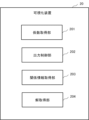
- FIG. 1 is a block diagram showing a configuration example of a visualization device according to a first embodiment
- FIG. 3 is a flowchart illustrating an example of the operation of the visualization device according to the first embodiment
- FIG. 2 is a block diagram showing an example of a configuration of a visualization device according to a second embodiment.
- FIG. 6 is an explanatory diagram showing an example of a screen in which weighting coefficients of feature quantities having a trade-off relationship are displayed adjacently.
- 2 is a flowchart showing an operation example 1 of the visualization device according to an explanation example 1.
- FIG. This is an example of a screen on which differences in weighting coefficients in a plurality of objective functions are displayed.
- 12 is a flowchart showing an operation example 2 of the visualization device according to the explanation example 1.
- FIG. 6 is an explanatory diagram showing an example of an objective function and a weighting coefficient obtained by learning examples for each expert.
- FIG. 6 is an explanatory diagram showing an example of a screen on which a comparison of weighting coefficients for each objective function and optimization results of job assignments for each persona are displayed.
- 12 is a flowchart illustrating an example of the operation of the visualization device according to Explanation Example 2.
- FIG. FIG. 2 is an explanatory diagram showing an example of the hardware configuration of a computer.
- Embodiments of a visualization method, a visualization device, a program, and a non-temporary recording medium for recording a program according to the present disclosure will be described in detail below with reference to the drawings. This embodiment does not limit the disclosed technology.
- an optimization problem is to find a solution that maximizes or minimizes a certain objective function under given constraints.
- the objective function uses a feature amount as a viewpoint for evaluating the goodness of the optimization target.
- the weighting of the feature values may be set based on experience or the like, or may be obtained by learning based on the subject's decision-making history.
- Target people include experts. There may be multiple subjects. Constraints are items that must be observed during decision making.
- the feature amount, ie, the viewpoint, is an item that the subject considers when making a decision.
- FIG. 1 is a block diagram showing a configuration example of a visualization device according to a first embodiment.
- a user performs optimization using a learned objective function, but needs to select an objective function that matches his/her intention. Therefore, the visualization device 10 visualizes the target person's intention in the objective function.
- the visualization device 10 includes a coefficient acquisition section 101 and an output control section 102.
- the coefficient acquisition unit 101 acquires, for each of a plurality of different objective functions, a weighting coefficient for each of a plurality of feature quantities common to the plurality of objective functions.
- the plurality of feature amounts may be common to the plurality of objective functions.
- at least some of the plurality of feature quantities may be feature quantities that exist in some of the plurality of objective functions.
- Multiple objective functions are criteria for deriving optimal solutions for the same action.
- the plurality of objective functions may be obtained by learning based on a plurality of different decision-making histories. This learning is, for example, reverse reinforcement learning. For example, there may be decision-making histories for each subject (for example, an expert), or there may be decision-making histories for the same subject at different timings, such as in different time zones.
- an action here includes, for example, work.
- operations may be used for explanation.
- an action can be something like determining the order of tasks, scheduling such as allocating shifts, matching such as assigning tasks, and allocating resources such as determining the combination of dishes within the calorie limit. This may be a task of determining a combination, and is not particularly limited.
- a weighting coefficient is assigned to each feature amount.
- the weighting coefficient of each feature represents the degree to which each feature influences the solution of each objective function. That is, the feature amounts that are considered important differ for each objective function, and the weighting coefficient represents, for example, which feature amount is considered important in the objective function.
- the output control unit 102 outputs weighting coefficients for each of the plurality of feature quantities for each of the plurality of objective functions so that they can be compared.
- the output format of the output control unit 102 is not particularly limited.
- the output control unit 102 may display each weighting coefficient on a display device, or may output the weighting coefficients as audio to an audio output device.
- An output device such as a display device or an audio output device may be provided in the visualization device 10, or may be provided in a device connected to the visualization device 10 via a communication network or the like.
- the output control unit 102 may output the weighting coefficients of each of the plurality of feature quantities in line for each of the plurality of objective functions.
- the order in which the weighting coefficients are arranged is not particularly limited.
- the output control unit 102 may arrange the weighting coefficients in a predetermined order, or may arrange the weighting coefficients in a specified order.
- the output control unit 102 may output the weighting coefficients in such a way that the feature quantities in a trade-off relationship are adjacent to each other.
- the output control unit 102 may output a graph of the weighting coefficients of each of the plurality of feature amounts.
- the type of graph is not particularly limited, such as a bar graph, pie chart, band graph, etc.
- the order in which the weighting coefficients are arranged in a graph is not particularly limited.
- the order of the weighting coefficients when graphed may be the order described above.
- FIG. 2 is a flowchart showing an example of the operation of the visualization device 10 according to the first embodiment.
- the visualization device 10 acquires the weighting coefficient of each feature amount for each objective function (step S101).
- the visualization device 10 outputs weighting coefficients of each feature amount for each objective function in a manner that allows comparison (step S102).
- the visualization device 10 acquires the weighting coefficient of each feature amount for each objective function, and outputs the acquired weighting coefficients so that they can be compared. This makes it possible to visualize what was learned or set based on the intention. Therefore, it is possible to improve the ease of checking the objective function. That is, the intent of each objective function is displayed in a format that is easier for the user to understand. Thereby, for example, the user can gain a sense of understanding as to what intention the solution obtained by the objective function was obtained. Note that at least some of the plurality of objective functions may be objective functions obtained by multi-objective optimization.
- each functional unit may be realized by one device.
- each functional unit may be realized by one device, such as one server or one terminal device that can be operated by a user.
- each functional unit may be realized by a plurality of devices like a visualization system.
- Embodiment 2 Next, Embodiment 2 will be described in detail with reference to the drawings. Hereinafter, a description of contents that overlap with the above description will be omitted to the extent that the description of the second embodiment is not unclear.
- FIG. 3 is a block diagram showing an example of the configuration of the visualization device according to the second embodiment.
- the visualization device 20 includes a coefficient acquisition section 201, an output control section 202, a relational information acquisition section 203, and a solution acquisition section 204.
- a relational information acquisition unit 203 and a solution acquisition unit 204 are added to the first embodiment.
- the coefficient acquisition section 201 and the output control section 202 have the basic functions of the coefficient acquisition section 101 and the output control section 102 described in the first embodiment, respectively.
- the visualization device 20 may have information on a plurality of objective functions.
- the coefficient acquisition unit 201 acquires the weighting coefficient for each of the plurality of feature amounts for each of the objective functions.
- the output control unit 202 outputs the weighting coefficients obtained for each of the plurality of objective functions so that they can be compared.
- Explanation example 1 and explanation example 2 will be used to explain the relational information acquisition unit 203, solution acquisition unit 204, and output control unit 202 in more detail.
- Example 1 shows an example in which weighting coefficients of feature amounts are graphed and displayed. Here, an example in which a graph of weighting coefficients is displayed will be explained using Example 1 and Example 2.
- Example 1 is an example in which weighting coefficients of feature quantities in a trade-off relationship are displayed adjacent to each other for each objective function. For example, suppose that an objective function for an optimization problem that solves shift scheduling tasks for store staff is learned in store operations. In a case where it is better to have low labor costs, but want to secure a large number of store employees, there is a trade-off relationship between the feature amounts related to personnel costs and the feature amounts related to securing the number of employees.
- the relational information acquisition unit 203 obtains relational information representing a feature quantity having a trade-off relationship among a plurality of feature quantities. Whether at least two feature quantities are in a trade-off relationship may be determined manually, or may be determined depending on whether predetermined conditions are met. That is, the related information may be created manually, or may be created depending on whether predetermined conditions are met.
- the output control unit 202 Based on the relationship information, the output control unit 202 adjusts each of the plurality of feature quantities for each of the plurality of objective functions so that the weighting coefficients of the feature quantities having a trade-off relationship among the plurality of feature quantities are adjacent to each other. Output the weighting coefficients in order. For example, the output control unit 202 may graph the weighting coefficients of each of the plurality of feature quantities so that the weighting coefficients of the feature quantities in a trade-off relationship are adjacent to each other.
- the output control unit 202 may output information indicating that there is a trade-off relationship between a plurality of different feature quantities.
- the information indicating that there is a trade-off relationship may be a symbol such as an arrow, a number, a character, or a color.
- the output control unit 202 may output information indicating that the difference is equal to or greater than the threshold.
- FIG. 4 is an explanatory diagram showing an example of a screen in which weighting coefficients of feature quantities having a trade-off relationship are displayed adjacently.
- a graph is shown in which weighting coefficients of feature amounts can be compared for each objective function.
- the horizontal axis represents each feature amount
- the vertical axis represents a weighting coefficient.
- the arrows in both directions are information indicating that the feature amounts are in a trade-off relationship.
- the feature amount A and the feature amount D are in a trade-off relationship.
- the feature amount C and the feature amount F are in a trade-off relationship.
- the weighting coefficient of the feature quantity A is smaller than the weighting coefficient of the feature quantity D.
- the weighting coefficient of the feature quantity D is smaller than the weighting coefficient of the feature quantity A. Therefore, for example, a user who wants to place more importance on personnel costs may select objective function X, and a user who wants to place more importance on securing the number of people may select objective function Y.
- the output control unit 202 when the difference between the weighting coefficients of a plurality of different feature quantities in a trade-off relationship is equal to or greater than the threshold, the output control unit 202 outputs information indicating that the difference is equal to or greater than the threshold.
- the threshold value is not particularly limited as long as it is determined in advance.
- the output control unit 202 may highlight a plurality of different feature amounts in a trade-off relationship when the difference is greater than or equal to a threshold value.
- information indicating that the difference is greater than or equal to the threshold is represented by a dotted line.
- in the graph of the objective function is highlighted and surrounded by a dotted line.
- the difference between the weighting coefficient of feature C and the weighting coefficient of feature F is greater than or equal to the threshold, so the weighting coefficient of feature C and the weighting coefficient of feature F are surrounded by dotted lines. and highlighted.
- FIG. 5 is a flowchart showing an example 1 of operation of the visualization device 20 according to the first example.
- the visualization device 20 acquires the weighting coefficient of the feature amount for each objective function (step S201).
- the relational information acquisition unit 203 obtains relational information representing a feature quantity having a trade-off relationship among a plurality of feature quantities (step S202).
- the output control unit 202 causes the display device to display the weighting coefficients of the feature quantities in a trade-off relationship for each objective function so that they are adjacent to each other (step S203).
- Example 2 describes an example in which differences in weighting coefficients for each of a plurality of feature quantities in a plurality of objective functions are displayed. Note that Example 2 may be combined with Example 1.
- the output control unit 202 outputs the difference in weighting coefficients for each of the plurality of feature amounts in the plurality of objective functions. There are an objective function Output the difference.
- the output control unit 202 may output the differences between the weighting coefficients of each of the plurality of feature quantities side by side.
- the output control unit 202 may display the features side by side so that the differences in the weighting coefficients of the feature amounts in a trade-off relationship are adjacent to each other.
- the output control unit 202 may output a graph of the difference between the weighting coefficients of each of the plurality of feature quantities.
- the output control unit 202 may output a graph so that the differences in the weighting coefficients of the feature amounts in a trade-off relationship are adjacent to each other.
- FIG. 6 is an example of a screen where differences in weighting coefficients for multiple objective functions are displayed.
- FIG. 6 shows a graph that allows comparison of differences in weighting coefficients of feature quantities in a plurality of objective functions.
- the horizontal axis represents each feature amount
- the vertical axis represents the difference in weighting coefficients.
- FIG. 6 shows the difference in feature amounts between objective function X and objective function Y.
- the vertical axis is, for example, a value (difference) obtained by subtracting the weighting coefficient of the objective function Y from the weighting coefficient of the objective function X.
- the output control unit 202 may output differences in feature amounts that are in a trade-off relationship adjacent to each other.
- arrows in both directions are information indicating that the feature amounts are in a trade-off relationship.
- the feature amount A and the feature amount D are in a trade-off relationship.
- the feature amount C and the feature amount F are in a trade-off relationship.
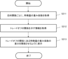
- FIG. 7 is a flowchart showing a second operation example of the visualization device 20 according to the first explanation example.
- the coefficient acquisition unit 201 acquires the weighting coefficient of the feature amount for each objective function (step S211).
- the relational information acquisition unit 203 obtains relational information representing a feature quantity having a trade-off relationship among a plurality of feature quantities (step S212).
- the output control unit 202 causes the display device to display the features in a trade-off relationship so that the differences in weighting coefficients are adjacent to each other (step S213).
- Example 2 In Explanation Example 2, the weighting coefficients for each of a plurality of objective functions are presented in a comparative manner, and the results obtained when an optimization problem is actually solved using the objective functions are presented for each objective function.
- FIG. 8 is an explanatory diagram showing an example of the objective function and weighting coefficients obtained by learning examples for each expert.
- FIG. 8 shows features of an objective function and weighting coefficients of the features for optimizing work assignments.
- an example will be given in which the objective functions for experts XX and YY are obtained as learning examples.
- An example will be given in which when Mr. XX is used as a learning example, an objective function ZX is obtained, and when Mr. YY is used as a learning example, an objective function ZY is obtained.
- the feature values include "match with career aspirations,” “family circumstances,” “match with experience,” and “match with personality.”
- the objective function ZX and the objective function ZY each have the same feature quantity, but the weighting coefficients of the feature quantities are different.
- the objective function ZX has a lower weighting coefficient value for the feature quantity "family circumstances” and a higher weighting coefficient value for the feature quantity "consistency with experience” than the objective function ZY. Therefore, for the objective function ZX, "matching with experience” is more important than for the objective function ZY.
- the objective function ZY places more emphasis on "family circumstances” than the objective function ZX.
- the solution acquisition unit 204 acquires, for each of the plurality of objective functions, a solution obtained based on the objective function to which information representing a predetermined state is given.
- the predetermined state may be, for example, a representative state.
- the representative state may be, for example, a state specified by the user.
- the representative state may be a state in which the user is placed, or a state created empirically by the user.
- a typical state is a state that can be judged differently by experts.
- the specific state may be determined by the task to be optimized.
- the data used to calculate the feature quantity of the objective function is state data, and its typical state is a predetermined state, for example, a representative state.
- a predetermined state for example, a representative state.
- the information representing the typical state may be sales performance data for each product. Further, the information representing the typical state may be data on a campaign such as a discount or a discount based on the sale of a combination of products.
- the information representing typical conditions may be environmental data regarding the environment such as weather, temperature, and humidity, and calendar data such as days of the week, holidays, and summer vacation.
- the information representing the representative state may be event data such as nearby events and dates and times of events.
- Information representing a typical state may be inventory data such as delivery, disposal, etc.
- the information representing a representative state may be persona data such as a persona representing a person's state, such as the employee's skills, experience, and desired career. Further, the information representing the typical state may be data such as a shift preference list. Further, the information representing the representative state may be predictive data such as expected workload.
- a typical state when environmental data is used as state data is shown below. If the environmental data is "weather, temperature, and humidity”, a typical state is “sunny weather, temperature is 30 degrees, and humidity is 20%", and vector data that represents these values is required. is information representing a typical state.
- information representing typical conditions may include environmental data, calendar data, event data, sales forecasts, current inventory, and spare capacity in the backyard.
- persona data may be used as information representing representative states.
- the career type wishes of Mr. AA and Mr. BBB and the degree of match between the career type and the task are shown below.
- Mr. AA's desired career type is b
- Mr. BB's desired career type is c.
- the degree of matching between career type a and the task is 0.
- the degree of match between career type b and the task is 1.
- the degree of match between career type c and the task is 0.
- the degree of matching between carrier type d and the task is 0.
- the degree of match between the task and Mr. AA's career aspirations is 1
- the degree of match between the task and Mr. BB's career hopes is 0, and so on.
- the decision whether to ultimately assign the task to Mr. AA or to Mr. BB, taking into account other features (for example, matching with experience) depends on which feature and how important it is. It depends on the weighting.
- state data related to "degree of match with career aspirations" as shown in Figure 8 is used, and as information representing a typical state, the optimization results may differ depending on the objective function.
- wax state data is selected.
- a typical situation is ⁇ Mr. AA, who has no experience but whose career aspirations match the task x to which he wants to assign someone, and Mr. BB, whose career aspirations match but whose career aspirations match.'' Prepare as an example of the information to be represented. For example, if information representing such a typical state is used, it is expected that the assignment result, which is the optimization result, will be different between an objective function emphasizing experience and an objective function emphasizing degree of match with career aspirations.
- the solution acquisition unit 204 derives a solution by providing information representing a predetermined state for each of the plurality of objective functions. Thereby, the solution acquisition unit 204 can acquire the solution.
- the solution acquisition unit 204 may acquire, from another device, a solution derived by another device for each of the plurality of objective functions.
- the output control unit 202 outputs the weighting coefficients for each of the plurality of objective functions in a manner that can be compared, and also outputs the obtained solution. This allows you to check the influence of the weighting coefficients on the solution while looking at the weighting coefficients and the solution.
- the solution acquisition unit 204 may also provide information representing each of a plurality of different states to each of the plurality of objective functions, and obtain a solution obtained based on the objective function. For example, in the case of a persona, the solution acquisition unit 204 provides each persona data to each of a plurality of objective functions, and acquires a solution obtained based on the objective function. Then, the output control unit 202 outputs the solution obtained for each of the plurality of objective functions for each of the plurality of states.
- FIG. 9 is an explanatory diagram showing an example of a screen on which a comparison of weighting coefficients for each objective function and optimization results of job assignments for each persona are displayed. For example, let us assume that there is a decision (optimization problem) to allocate job e and job f to two employees, AA and BB. Please note that one person will be assigned to each job. Also, it is desirable for job e to have experience in the AA sales department, but it is a high-load job.
- the weighting coefficients of the feature quantities are displayed for each of the objective functions ZX and ZY, which determine which job is assigned to which persona (employee).
- persona AA and persona BB are representative states corresponding to employees.
- her work experience includes sales experience at the AA sales department and BB sales department, and her family situation is that she has been raising a child since December 2020.
- her work history includes planning experience at the CC Planning Department and sales experience at the BB Sales Department, and her family circumstances include no childcare or nursing care.
- optimization results are displayed, which are the solutions obtained from the objective functions ZX and ZY, respectively, which determine which job is assigned to which persona (employee).
- the output control unit 202 may highlight the weighting coefficients for each feature amount if the difference in the weighting coefficients is equal to or greater than a threshold value.
- the method of highlighting is not particularly limited. In FIG. 9, since there is a large difference in the feature amount "family circumstances" between the objective function ZX and the objective function ZY, two weighting coefficients are highlighted and surrounded by a dotted line frame. Furthermore, since there is a large difference in the feature quantity "matching with experience" between the objective function ZX and the objective function ZY, the two weighting coefficients are highlighted and surrounded by a dotted line frame.
- the objective function ZX has a lower weighting coefficient value for the feature quantity "family circumstances” and a higher weighting coefficient value for the feature quantity "consistency with experience” than the objective function ZY. Therefore, for the objective function ZX, "matching with experience” is more important than for the objective function ZY. On the other hand, the objective function ZY places more emphasis on "family circumstances” than the objective function ZX.
- Job e is a job for which it is desirable to have experience in the AA sales department, so in the optimization results for the objective function ZX, where "match with experience" is emphasized, job e is assigned to persona AA, and persona BB is assigned job e. Job f is assigned.
- the output control unit 202 may highlight the solutions if the differences between the solutions due to different states, such as personas, are greater than or equal to a specific difference.
- the output control unit 202 displays all the information on one screen, but it may display the information on multiple screens that can be switched.
- FIG. 10 is a flowchart illustrating an example of the operation of the visualization device 20 according to Explanation Example 2.
- the coefficient acquisition unit 201 acquires the weighting coefficient of the feature amount for each objective function (step S221).
- the solution acquisition unit 204 acquires a solution for each state for each objective function (step S222).
- the output control unit 202 causes the display device to display the weighting coefficients and solutions of the feature amounts for each objective function (step S223).
- the visualization device 20 arranges and outputs weighting coefficients such that weighting coefficients of feature quantities having a trade-off relationship among a plurality of feature quantities are adjacent to each other. Thereby, it is possible to more easily confirm which of the plurality of feature quantities having a trade-off relationship in each objective function has a stronger influence.
- the visualization device 20 outputs information indicating that the difference is equal to or greater than the threshold. This makes it possible to easily confirm the influence of intentions in a trade-off relationship.
- the visualization device 20 outputs information indicating that there is a trade-off relationship. As a result, it is possible to easily understand which of the plurality of feature quantities has a trade-off relationship. In addition, the visualization device 20 can easily understand which feature quantity has a trade-off relationship among the plurality of feature quantities. Outputs the difference in weighting coefficients. Thereby, it is possible to easily check the difference in the influence of each intention between different objective functions.
- the visualization device 20 outputs, for each of the plurality of objective functions, a solution obtained based on the objective function to which information representing a predetermined state is given, as well as a weighting coefficient for each of the plurality of feature quantities. This makes it possible to easily check the influence of differences in weighting coefficients on the solution.
- the visualization device 20 may output, for each objective function, a solution obtained based on the objective function for each of the plurality of states. Thereby, it is possible to easily check the influence on the solution due to the difference in weighting coefficients in a plurality of different states.
- the visualization device may have a configuration in which each functional unit and a part of information are included.
- the visualization device 20 in the second embodiment may include a coefficient acquisition section 201, an output control section 202, and a relational information acquisition section 203.
- the visualization device 20 in the second embodiment may include a coefficient acquisition section 201, an output control section 202, and a solution acquisition section 204.
- each of the embodiments described above is not limited to the example described above, and can be modified in various ways. Further, the configuration of the visualization device in each embodiment is not particularly limited. Each functional unit described in the embodiment may be realized by one device (visualization device), or may be realized by a plurality of different devices like a visualization system.
- buttons, information display fields, input fields, etc. may be added to each screen. Further, in each screen, the position, color, and size of each item such as a button, an input field, a display field, etc. are not particularly limited. Also, the background color of the screen, etc. may be changed.
- the display device that is the output device is provided with a device different from the visualization devices 10 and 20, the process of generating screen information etc. to be displayed on the display device is performed by the output control unit. 102, 202, or a device including a display device.
- FIG. 11 is an explanatory diagram showing an example of the hardware configuration of a computer.
- part or all of each device can be realized using any combination of a computer 30 and a program as shown in FIG. 11, for example.
- the computer 30 includes, for example, a processor 301, a ROM (Read Only Memory) 302, a RAM (Random Access Memory) 303, a storage device 304, a communication interface 305, and an input/output interface 306.
- a processor 301 for example, a central processing unit (CPU) 301, a central processing unit (CPU) 301, a graphics processing unit (GPU) 301, a graphics processing unit (Ga), a graphics processing unit (GPU) , a graphics processing unit (GPU) , a graphics processing unit (GPU) , and a graphics processing unit (GPU) 304, a graphics processing unit (GPU) a graphics processing unit 304, and a graphics processing unit 304, a graphics processing unit (GPU) a graphics processing unit (GPU) 304, a graphics processing unit (GPU) 304, a graphics processing unit (GPU) 304, a graphics processing unit (GPU) 304, a graphics processing unit (GPU
- a processor 301 controls the entire computer 30.
- Examples of the processor 301 include a CPU (Central Processing Unit), a DSP (Digital Signal Processor), and a GPU (Graphics Processing Unit). There may be a plurality of processors 301.
- the computer 30 includes a ROM 302, a RAM 303, a storage device 304, and the like as storage units.
- Examples of the storage device 304 include semiconductor memory such as flash memory, HDD (Hard Disk Drive), SSD (Solid State Drive), and the like.
- the storage device 304 stores OS (Operating System) programs, application programs, programs according to each embodiment, and the like.
- the ROM 302 stores application programs, programs according to each embodiment, and the like.
- the RAM 303 is used as a work area for the processor 301.
- the processor 301 loads programs stored in the storage device 304, ROM 302, etc. The processor 301 then executes each process (each processing instruction) coded in the program. Furthermore, the processor 301 may download various programs via the communication network NT. Further, the processor 301 functions as part or all of the computer 30. The processor 301 may then execute the processes or instructions in the illustrated flowchart based on the program.
- the communication interface 305 is connected to a communication network NT such as a LAN (Local Area Network) or a WAN (Wide Area Network) through a wireless or wired communication line.
- a communication network NT such as a LAN (Local Area Network) or a WAN (Wide Area Network) through a wireless or wired communication line.
- the communication network NT may be composed of a plurality of communication networks.
- the computer 30 is connected to an external device or an external computer 30 via the communication network NT.
- the communication interface 305 serves as an interface between the communication network NT and the inside of the computer 30.
- the communication interface 305 controls the input and output of data from external devices and the external computer 30.
- the input/output interface 306 is connected to at least one of an input device, an output device, and an input/output device.
- the connection method may be wireless or wired.
- Examples of the input device include a keyboard, a mouse, and a microphone.
- Examples of the output device include a display device, a lighting device, and a speaker that is an audio output device that outputs audio.
- examples of the input/output device include a touch panel display. Note that the input device, output device, input/output device, etc. may be built into the computer 30 or may be externally attached.
- Computer 30 may include some of the components shown in FIG. Computer 30 may include components other than those shown in FIG.
- the computer 30 may include a drive device or the like.
- the processor 301 may read programs and data stored in a recording medium attached to a drive device or the like to the RAM 303. Examples of non-temporary tangible recording media include optical disks, flexible disks, magneto-optical disks, USB (Universal Serial Bus) memories, and the like.
- the computer 30 may include an input device such as a keyboard and a mouse. Computer 30 may have an output device such as a display. Further, the computer 30 may each have an input device, an output device, and an input/output device.
- the computer 30 may include various sensors (not shown). The type of sensor is not particularly limited.
- the visualization device may be realized by any combination of computers and programs that are different for each component.
- a plurality of components included in the visualization device may be realized by an arbitrary combination of one computer and a program.
- each device such as the visualization device may be realized by a circuit for a specific purpose. Further, part or all of each device may be realized by a general-purpose circuit including a processor such as a field programmable gate array (FPGA). Further, a part or all of each device may be realized by a combination of a circuit for a specific use, a general-purpose circuit, or the like. Also, these circuits may be a single integrated circuit. Alternatively, these circuits may be divided into multiple integrated circuits. Further, the plurality of integrated circuits may be configured by being connected via a bus or the like.
- FPGA field programmable gate array
- each component of each device is realized by a plurality of computers, circuits, etc.
- the plurality of computers, circuits, etc. may be arranged centrally or in a distributed arrangement.
- the visualization method described in each embodiment is realized by being executed by a computer such as a visualization device. Further, the visualization method is realized by a computer such as a visualization device executing a program prepared in advance.
- the programs described in each embodiment are recorded on a computer-readable recording medium such as an HDD, SSD, flexible disk, optical disk, flexible disk, magneto-optical disk, or USB memory. Then, the program is executed by being read from the recording medium by the computer.
- the program may also be distributed via the communications network NT.
- each component of each device such as the visualization device in each embodiment described above may be realized in hardware, like a computer.
- each component may be realized by a computer or firmware based on program control.
- Each of the plurality of objective functions is an objective function generated by inverse reinforcement learning, The visualization method according to any one of Supplementary Notes 1 to 7.
- coefficient obtaining means for obtaining weighting coefficients for each of the plurality of feature quantities for each of the plurality of different objective functions; output control means for outputting the weighting coefficients obtained for each of the plurality of objective functions in a comparable manner; Equipped with The weighting coefficient for each of the plurality of feature quantities represents the degree to which the feature quantity influences the solution of each of the plurality of objective functions, Visualization device.
- the visualization device according to appendix 9.
- solution acquisition means for each of the plurality of objective functions, solution acquisition means is provided for acquiring a solution obtained based on the objective function to which information representing a predetermined state is given, The output control means outputs the weighting coefficients for each of the plurality of objective functions in a comparable manner, and outputs the obtained solution.
- the visualization device according to appendix 9. Each of the plurality of objective functions is an objective function generated by inverse reinforcement learning, The visualization device according to any one of Supplementary Notes 9 to 11.
Landscapes
- Engineering & Computer Science (AREA)
- Theoretical Computer Science (AREA)
- Physics & Mathematics (AREA)
- Computing Systems (AREA)
- General Engineering & Computer Science (AREA)
- General Physics & Mathematics (AREA)
- Mathematical Physics (AREA)
- Software Systems (AREA)
- User Interface Of Digital Computer (AREA)
Priority Applications (2)
| Application Number | Priority Date | Filing Date | Title |
|---|---|---|---|
| PCT/JP2022/010900 WO2023170918A1 (ja) | 2022-03-11 | 2022-03-11 | 可視化方法、可視化装置、および記録媒体 |
| JP2024505807A JP7729460B2 (ja) | 2022-03-11 | 2022-03-11 | 可視化方法、可視化装置、およびプログラム |
Applications Claiming Priority (1)
| Application Number | Priority Date | Filing Date | Title |
|---|---|---|---|
| PCT/JP2022/010900 WO2023170918A1 (ja) | 2022-03-11 | 2022-03-11 | 可視化方法、可視化装置、および記録媒体 |
Publications (1)
| Publication Number | Publication Date |
|---|---|
| WO2023170918A1 true WO2023170918A1 (ja) | 2023-09-14 |
Family
ID=87936536
Family Applications (1)
| Application Number | Title | Priority Date | Filing Date |
|---|---|---|---|
| PCT/JP2022/010900 Ceased WO2023170918A1 (ja) | 2022-03-11 | 2022-03-11 | 可視化方法、可視化装置、および記録媒体 |
Country Status (2)
| Country | Link |
|---|---|
| JP (1) | JP7729460B2 (https=) |
| WO (1) | WO2023170918A1 (https=) |
Cited By (4)
| Publication number | Priority date | Publication date | Assignee | Title |
|---|---|---|---|---|
| CN120316198A (zh) * | 2025-06-11 | 2025-07-15 | 安徽信捷智能科技有限公司 | 基于多要素排放因子的智慧园区碳排放监测方法及系统 |
| CN120629846A (zh) * | 2025-08-11 | 2025-09-12 | 杭州玟雅科技股份有限公司 | 一种开关柜局部放电与温升特性的关联诊断方法及系统 |
| CN120746345A (zh) * | 2025-09-03 | 2025-10-03 | 南京市水产科学研究所(南京市水产技术推广站、南京市水生动物疫病预防控制中心) | 一种水体抗菌剂智能投放策略生成系统及方法 |
| CN120952490A (zh) * | 2025-10-17 | 2025-11-14 | 海博泰科技(青岛)有限公司 | 一种船舶智能排程方法、装置、电子设备及存储介质 |
Citations (3)
| Publication number | Priority date | Publication date | Assignee | Title |
|---|---|---|---|---|
| WO2021130916A1 (ja) * | 2019-12-25 | 2021-07-01 | 日本電気株式会社 | 意図特徴量抽出装置、学習装置、方法およびプログラム |
| WO2021181459A1 (ja) * | 2020-03-09 | 2021-09-16 | 株式会社日立ビルシステム | エレベーター情報表示装置およびエレベーター情報表示方法 |
| WO2021245733A1 (ja) * | 2020-06-01 | 2021-12-09 | 日本電気株式会社 | 脳画像解析装置、制御方法、及びコンピュータ可読媒体 |
-
2022
- 2022-03-11 JP JP2024505807A patent/JP7729460B2/ja active Active
- 2022-03-11 WO PCT/JP2022/010900 patent/WO2023170918A1/ja not_active Ceased
Patent Citations (3)
| Publication number | Priority date | Publication date | Assignee | Title |
|---|---|---|---|---|
| WO2021130916A1 (ja) * | 2019-12-25 | 2021-07-01 | 日本電気株式会社 | 意図特徴量抽出装置、学習装置、方法およびプログラム |
| WO2021181459A1 (ja) * | 2020-03-09 | 2021-09-16 | 株式会社日立ビルシステム | エレベーター情報表示装置およびエレベーター情報表示方法 |
| WO2021245733A1 (ja) * | 2020-06-01 | 2021-12-09 | 日本電気株式会社 | 脳画像解析装置、制御方法、及びコンピュータ可読媒体 |
Non-Patent Citations (1)
| Title |
|---|
| NAKAO YURI: " 4H1-GS-11b-03 Toward criticizable system to support personally critical decisions", THE 35TH ANNUAL CONFERENCE OF THE JAPANESE SOCIETY FOR ARTIFICIAL INTELLIGENCE, 2021, 8 June 2021 (2021-06-08), pages 1 - 4, XP093089710, Retrieved from the Internet <URL:https://www.jstage.jst.go.jp/article/pjsai/JSAI2021/0/JSAI2021_4H1GS11b03/_pdf/-char/ja> [retrieved on 20231009] * |
Cited By (4)
| Publication number | Priority date | Publication date | Assignee | Title |
|---|---|---|---|---|
| CN120316198A (zh) * | 2025-06-11 | 2025-07-15 | 安徽信捷智能科技有限公司 | 基于多要素排放因子的智慧园区碳排放监测方法及系统 |
| CN120629846A (zh) * | 2025-08-11 | 2025-09-12 | 杭州玟雅科技股份有限公司 | 一种开关柜局部放电与温升特性的关联诊断方法及系统 |
| CN120746345A (zh) * | 2025-09-03 | 2025-10-03 | 南京市水产科学研究所(南京市水产技术推广站、南京市水生动物疫病预防控制中心) | 一种水体抗菌剂智能投放策略生成系统及方法 |
| CN120952490A (zh) * | 2025-10-17 | 2025-11-14 | 海博泰科技(青岛)有限公司 | 一种船舶智能排程方法、装置、电子设备及存储介质 |
Also Published As
| Publication number | Publication date |
|---|---|
| JP7729460B2 (ja) | 2025-08-26 |
| JPWO2023170918A1 (https=) | 2023-09-14 |
Similar Documents
| Publication | Publication Date | Title |
|---|---|---|
| WO2023170918A1 (ja) | 可視化方法、可視化装置、および記録媒体 | |
| US10114875B2 (en) | Dashboard controls to manipulate visual data | |
| JP7479251B2 (ja) | 計算機システムおよび情報処理方法 | |
| Beloglazov et al. | Improving productivity in design and development of information technology (IT) service delivery simulation models | |
| Billah et al. | Empirical information criteria for time series forecasting model selection | |
| JP2022103288A (ja) | 情報処理装置、人事情報管理支援方法及びプログラム | |
| JP2021043477A (ja) | 需要予測装置、需要予測方法、及びプログラム | |
| WO2014061229A1 (ja) | 情報システム構築支援装置、情報システム構築支援方法および情報システム構築支援プログラム | |
| US20210200590A1 (en) | Computer system and method for determining of resource allocation | |
| Luna-Reyes et al. | An enterprise view for artificial intelligence capability and governance: A system dynamics approach | |
| Manzur et al. | xArchiMate: Enterprise Architecture simulation, experimentation and analysis | |
| US20170046801A1 (en) | Managing the size of food portions | |
| JP7382093B1 (ja) | 人材管理システムおよび人材管理プログラム | |
| TW202343367A (zh) | 訂單資訊之處理方法及電子裝置 | |
| JP2019164738A (ja) | 予測装置、予測方法、予測プログラム、生成装置、生成方法及び生成プログラム | |
| JP2022101879A (ja) | 需要予測装置、需要予測方法およびプログラム | |
| JP7226756B2 (ja) | 組織ポテンシャルの予測装置、予測方法、プログラム、および記録媒体 | |
| JP7718421B2 (ja) | 情報処理装置、情報処理方法、およびプログラム | |
| JP7567463B2 (ja) | 情報処理方法、情報処理装置、及び、プログラム | |
| CN110990637A (zh) | 网络图谱的构建方法及其装置 | |
| JP7582195B2 (ja) | 情報処理装置、情報処理方法、およびプログラム | |
| JP7480844B2 (ja) | 需要予測装置、需要予測方法、及び需要予測プログラム | |
| JP7736164B2 (ja) | 可視化方法、可視化装置、およびプログラム | |
| US20170329654A1 (en) | Presenting a synthesized alert using a digital personal assistant | |
| Chatterjee | Team mindfulness: a vital tool for boosting learning and adaptive capabilities |
Legal Events
| Date | Code | Title | Description |
|---|---|---|---|
| 121 | Ep: the epo has been informed by wipo that ep was designated in this application |
Ref document number: 22930899 Country of ref document: EP Kind code of ref document: A1 |
|
| ENP | Entry into the national phase |
Ref document number: 2024505807 Country of ref document: JP Kind code of ref document: A |
|
| NENP | Non-entry into the national phase |
Ref country code: DE |
|
| 122 | Ep: pct application non-entry in european phase |
Ref document number: 22930899 Country of ref document: EP Kind code of ref document: A1 |