WO2023170913A1 - 室内機、および空気調和機 - Google Patents
室内機、および空気調和機 Download PDFInfo
- Publication number
- WO2023170913A1 WO2023170913A1 PCT/JP2022/010882 JP2022010882W WO2023170913A1 WO 2023170913 A1 WO2023170913 A1 WO 2023170913A1 JP 2022010882 W JP2022010882 W JP 2022010882W WO 2023170913 A1 WO2023170913 A1 WO 2023170913A1
- Authority
- WO
- WIPO (PCT)
- Prior art keywords
- lid
- indoor unit
- leaf spring
- circuit board
- side wall
- Prior art date
- Legal status (The legal status is an assumption and is not a legal conclusion. Google has not performed a legal analysis and makes no representation as to the accuracy of the status listed.)
- Ceased
Links
Images




Classifications
-
- F—MECHANICAL ENGINEERING; LIGHTING; HEATING; WEAPONS; BLASTING
- F24—HEATING; RANGES; VENTILATING
- F24F—AIR-CONDITIONING; AIR-HUMIDIFICATION; VENTILATION; USE OF AIR CURRENTS FOR SCREENING
- F24F1/00—Room units for air-conditioning, e.g. separate or self-contained units or units receiving primary air from a central station
- F24F1/06—Separate outdoor units, e.g. outdoor unit to be linked to a separate room comprising a compressor and a heat exchanger
- F24F1/20—Electric components for separate outdoor units
-
- F—MECHANICAL ENGINEERING; LIGHTING; HEATING; WEAPONS; BLASTING
- F24—HEATING; RANGES; VENTILATING
- F24F—AIR-CONDITIONING; AIR-HUMIDIFICATION; VENTILATION; USE OF AIR CURRENTS FOR SCREENING
- F24F2130/00—Control inputs relating to environmental factors not covered by group F24F2110/00
- F24F2130/20—Sunlight
Definitions
- the present disclosure relates to an indoor unit and an air conditioner.
- the indoor unit of the air conditioner is equipped with a control device that controls the blower motor and heat exchanger.
- the electrical equipment box that houses the control device is provided with a wiring entrance through which wiring extending from the controlled object passes.
- Patent Document 1 discloses an electrical component box having an insertion portion through which wires of different thicknesses can pass.
- the number of wires connected to the control device varies depending on the model of air conditioning equipment.
- the opening area of the wiring entrance must be large enough to allow the maximum number of wires to pass through. For this reason, in models with a relatively small number of wires, gaps are created in the wire entrances and exits through which small animals such as insects or dust can enter.
- the present disclosure aims to provide an indoor unit that can adjust the opening area of a wiring entrance/exit of an electrical component box according to the number of wirings, and an air conditioner equipped with such an indoor unit. purpose.
- One aspect of the indoor unit according to the present disclosure is an indoor unit of an air conditioner, which includes a heat exchanger, a blower, a circuit board to which a plurality of wirings are connected, and an electrical component box housing the circuit board. and a casing that houses the heat exchanger, the blower, and the control device therein, the electrical component box includes a side wall portion surrounding the circuit board, and a side wall portion that covers the circuit board. It has a lid body and a leaf spring part provided on the lid body, the side wall part is provided with a plurality of notches through which the wirings are passed, and the leaf spring part has a plurality of leaf spring parts provided on the inner edge of the notch part. Press the wires against each other.
- One aspect of the air conditioner according to the present disclosure includes the above indoor unit and an outdoor unit.
- an indoor unit that can adjust the opening area of a wiring entrance/exit of an electrical component box according to the number of wirings, and an air conditioner equipped with such an indoor unit.
- the drawings appropriately indicate an X axis, a Y axis, and a Z axis.
- the X-axis indicates one of the horizontal directions.
- the Y axis indicates the other horizontal direction.
- the Z axis indicates the vertical direction.
- the horizontal direction along the X-axis will be referred to as the "front-back direction X”
- the horizontal direction along the Y-axis will be referred to as the "left-right direction Y”
- the vertical direction will be referred to as the "vertical direction Z.”
- the front-rear direction X, the left-right direction Y, and the vertical direction Z are directions that are orthogonal to each other.
- the side of the vertical direction Z that the Z-axis arrow points to (+Z side) is referred to as the upper side
- the side of the vertical direction Z that is opposite to the side that the Z-axis arrow points to (-Z side) is referred to as the lower side.
- the front-rear direction X the side toward which the X-axis arrow points (+X side) is the front side
- the front-rear direction X the side opposite to the side toward which the X-axis arrow points (-X side) is the rear side.
- the left-right direction Y is the left-right direction when the indoor unit of the following embodiment is viewed from the front (+X side).
- the side of the left-right direction Y that the Y-axis arrow points to (+Y side) is the right side
- the side of the left-right direction Y that is opposite to the side that the Y-axis arrow points to (-Y side) is the left side
- FIG. 1 is a schematic diagram showing a schematic configuration of an air conditioner 100 in an embodiment.
- the air conditioner 100 includes an outdoor unit 10, an indoor unit 20, and a circulation path section 18.
- the outdoor unit 10 is placed outdoors.
- the indoor unit 20 is placed indoors.
- the outdoor unit 10 and the indoor unit 20 are connected to each other by a circulation path section 18 through which a refrigerant 19 circulates.
- the air conditioner 100 can adjust the temperature of indoor air by exchanging heat between the refrigerant 19 flowing in the circulation path section 18 and the air in the room where the indoor unit 20 is placed.
- the refrigerant 19 include a fluorine-based refrigerant or a hydrocarbon-based refrigerant that has a low global warming potential (GWP).
- GWP global warming potential
- the outdoor unit 10 includes a housing 11, a compressor 12, a heat exchanger 13, a flow rate adjustment valve 14, a blower 15, a four-way valve 16, and an outdoor unit control section 17. Inside the housing 11, a compressor 12, a heat exchanger 13, a flow rate adjustment valve 14, a blower 15, a four-way valve 16, and an outdoor unit control section 17 are housed.
- the compressor 12, the heat exchanger 13, the flow rate adjustment valve 14, and the four-way valve 16 are provided in a portion of the circulation path portion 18 located inside the housing 11.
- the compressor 12, the heat exchanger 13, the flow rate adjustment valve 14, and the four-way valve 16 are connected by a portion of the circulation path portion 18 located inside the housing 11.
- the four-way valve 16 is provided in a portion of the circulation path section 18 that is connected to the discharge side of the compressor 12.
- the four-way valve 16 can reverse the direction of the refrigerant 19 flowing within the circulation path section 18 by switching a part of the circulation path section 18 .
- the path connected by the four-way valve 16 is the path shown by the solid line in the four-way valve 16 in FIG. 1
- the refrigerant 19 flows in the circulation path section 18 in the direction shown by the solid line arrow in FIG.
- the path connected by the four-way valve 16 is the path shown by the broken line in the four-way valve 16 in FIG. 1
- the refrigerant 19 flows in the circulation path portion 18 in the direction shown by the broken line arrow in FIG.
- the indoor unit 20 includes a housing 21, a heat exchanger 22, a blower 23, and a control device 24.
- the housing 21 houses a heat exchanger 22, a blower 23, and a control device 24 therein.
- the indoor unit 20 is capable of a cooling operation that cools the air in the room where the indoor unit 20 is placed, and a heating operation that warms the air in the room where the indoor unit 20 is placed.
- the refrigerant 19 flowing within the circulation path section 18 flows in the direction shown by the solid arrow in FIG. 1. That is, when the indoor unit 20 is operated for cooling, the refrigerant 19 flowing in the circulation path section 18 is transferred to the compressor 12, the heat exchanger 13 of the outdoor unit 10, the flow rate adjustment valve 14, and the heat exchanger 22 of the indoor unit 20. are circulated in this order and returned to the compressor 12.
- the heat exchanger 13 in the outdoor unit 10 functions as a condenser
- the heat exchanger 22 in the indoor unit 20 functions as an evaporator.
- the refrigerant 19 flowing within the circulation path section 18 flows in the direction shown by the broken line in FIG. That is, when the indoor unit 20 is operated for heating, the refrigerant 19 flowing in the circulation path section 18 is transferred to the compressor 12, the heat exchanger 22 of the indoor unit 20, the flow rate adjustment valve 14, and the heat exchanger 13 of the outdoor unit 10. are circulated in this order and returned to the compressor 12.
- the heat exchanger 13 in the outdoor unit 10 functions as an evaporator
- the heat exchanger 22 in the indoor unit 20 functions as a condenser.
- FIG. 2 is a perspective view of the indoor unit 20.
- FIG. 3 is an exploded view of the indoor unit 20.
- the indoor unit 20 is a wall-mounted indoor unit fixed to an indoor wall surface WS.
- the indoor unit 20 has a substantially rectangular parallelepiped shape that is long in the left-right direction Y.
- the blower 23 of this embodiment is a cross flow fan.
- the blower 23 extends in the left-right direction Y.
- the blower 23 rotates around a rotation axis R extending in the left-right direction Y.
- a drive motor 23a that rotates the blower 23 around the rotation axis R is disposed on the right side (+Y side) of the blower 23 in the left-right direction Y.
- the heat exchanger 22 of the indoor unit 20 is located in front of the blower 23 (+X side) and above (+Z side).
- the heat exchanger 22 cools or heats the air sucked into the blower 23.
- the heat exchanger 22 is provided with a pipe temperature sensor (not shown).
- the pipe temperature sensor measures the pipe temperature of the heat exchanger 22. The measurement result of the pipe temperature by the pipe temperature sensor is used for controlling the heat exchanger 22 and for indoor temperature and humidity.
- the housing 21 is a substantially rectangular box-shaped member that is long in the left-right direction Y.
- the housing 21 includes a back case 21a and a design panel 21b.
- the back case 21a is a substantially rectangular frame-shaped member that opens on the front side (+X side).
- the design panel 21b is located on the front side (+X side) of the back case 21a.
- the design panel 21b is attached to the back case 21a.
- the back case 21a has an air passage member 21c.
- the air path member 21c is a member that constitutes at least a portion of an air path through which air sucked into the housing 21 by the blower 23 passes.
- a drain pan assembly 26 and a sensor assembly 27 are arranged inside the housing 21. That is, the indoor unit 20 includes a drain pan assembly 26 and a sensor assembly 27.
- Sensor assembly 27 includes multiple sensors such as a temperature sensor, a humidity sensor, and a human sensor. The sensor assembly 27 measures the indoor conditions using respective sensors.
- the drain pan assembly 26 includes a drain pan main body 26a disposed directly below the heat exchanger 22, and a wind direction adjustment section 26b disposed at the outlet.
- the drain pan main body 26a receives condensed water generated on the surface of the heat exchanger 22 from below.
- the wind direction adjusting section 26b includes a wind direction adjusting plate 26c and a plate driving section 26d that changes the inclination angle of the wind direction adjusting plate 26c.
- the wind direction adjustment unit 26b adjusts the direction of air blown out from the inside of the housing 21 into the room at the air outlet.
- a plurality of wiring lines 39 are arranged inside the casing 21 .
- a plurality of wires 39 electrically connect the drive motor 23 a of the blower 23 , the pipe temperature sensor of the heat exchanger 22 , the plate drive section 26 d of the drain pan assembly 26 , and the sensor assembly 27 to the control device 24 .
- the control device 24 controls each part of the indoor unit 20. More specifically, the control device 24 controls the blower 23, the heat exchanger 22, the air direction adjustment unit 26b, etc. based on the measurement results of each sensor provided in the sensor assembly 27 and the heat exchanger 22, for example. do. Further, the control device 24 can communicate with the outdoor unit control section 17 (see FIG. 1) of the outdoor unit 10.
- the control device 24 is housed inside the housing 21.
- the control device 24 is located at the right (+Y side) end inside the housing 21 .
- the control device 24 is located outside the air flow path (suction air path and outlet air path).
- FIG. 4 is an exploded view of the control device 24.
- the control device 24 includes a first circuit board 31, a second circuit board 32, an electrical component box 30, and a wiring guide member 28.
- the electrical component box 30 accommodates a first circuit board 31 and a second circuit board 32. Furthermore, a wiring guide member 28 is fixed to the electrical component box 30.
- the first circuit board 31 is a control board that controls the blower 23, heat exchanger 22, air direction adjustment section 26b, etc. of the indoor unit 20.
- the first circuit board 31 includes a board main body 31a and a plurality of electronic components 31b mounted on the board main body 31a.
- the board surface of the board body 31a faces in the left-right direction Y.
- the plurality of electronic components 31b are mounted on both surfaces or any one surface of the board body 31a.
- the plurality of electronic components 31b include, for example, a transistor and a microcomputer.
- FIG. 5 and 6 are front views of the control device 24 viewed from the right side (+Y side). Note that in FIG. 5, illustration of the lid 50 is omitted. Similarly, in FIG. 6, illustration of a part of the lid body 50 (second lid part 52) is omitted.
- a plurality of wiring lines 39 are connected to the first circuit board 31.
- all the wirings 39 are connected to the surface facing the right side (+Y side) of the board main body 31a.
- all the wiring 39 or some of the wiring 39 may be connected to the surface facing the left side (-Y side) of the substrate main body 31a.
- the plurality of wiring lines 39 connect each part of the indoor unit 20 and the first circuit board 31.
- the plurality of wires 39 include power supply wires connecting the drive motor 23a of the blower 23 (see FIG. 3) and the first circuit board 31, signal wires, and a temperature sensor of the heat exchanger 22 (see FIG. 3).
- the plurality of wiring lines 39 may include wiring that connects the outdoor unit control section 17 (see FIG. 1) of the outdoor unit 10 and the control device 24 of the indoor unit 20.
- the second circuit board 32 is a power receiving board that receives a wireless signal from an operating device (not shown) that operates the indoor unit 20.
- the second circuit board 32 is connected to the first circuit board 31 by a connector (not shown).
- the second circuit board 32 is arranged on the front side (+X side) with respect to the first circuit board 31.
- the second circuit board 32 includes a board main body 32a and an electronic component 32b mounted on one surface of the board main body 32a.
- the mounting surface of the board body 32a faces the rear side (-X side) and the lower side (-Z side).
- the wiring guide member 28 is arranged below the electrical component box 30.
- the wiring guide member 28 has a wiring passage portion 28a extending in the vertical direction Z, and a wiring collecting portion 28b arranged below the wiring passage portion 28a.
- the wiring passage portion 28a extends in the vertical direction Z in a duct shape.
- a plurality of wires 39 are arranged in the wire passage portion 28a.
- the wiring passage portion 28a opens on the right side (+Y side), and the wiring 39 is inserted from the right side.
- the plurality of wires 39 extend in the vertical direction Z inside the wire passage portion 28a. That is, the wiring guide member 28 guides the plurality of wirings 39 from the lower end toward the upper end.
- the upper end portion of the wiring passage portion 28a is arranged below a wiring entrance 30a of an electrical component box 30, which will be described later.
- the lower end of the wiring passage section 28a is arranged above the wiring collection section 28b.
- the wiring aggregation unit 28b bundles the plurality of wirings 39.
- the plurality of wires 39 extending from each part within the indoor unit 20 are routed to the wire aggregation section 28b and are aggregated therein.
- the plurality of wires 39 bundled in the wire aggregation section 28b are guided to the wiring passage section 28a, extend upward through the wiring passage section 28a, and are guided to the housing space A of the electrical component box 30 through the wiring entrance 30a.
- the electrical component box 30 includes a case 40 and a lid 50.
- the case 40 is placed on the right side (-Y side) of the first circuit board 31.
- the case 40 has a box shape that surrounds the first circuit board 31 and the second circuit board 32 and opens on the right side (+Y side).
- the case 40 includes a board support case 41 and a protection case 42.
- the board support case 41 and the protection case 42 are stacked in the left-right direction Y. Board support case 41 and protective case 42 are fixed to each other.
- the board support case 41 of this embodiment is a molded product made of resin material.
- the protective case 42 of this embodiment is a press-worked product made of, for example, a metal material.
- the board support case 41 supports the first circuit board and the second circuit board 32.
- the protective case 42 is arranged on the left side ( ⁇ Y side) of the board support case 41 and reinforces the board support case 41. Furthermore, the protective case 42 protects the first circuit board 31 and the second circuit board 32 housed in the electrical component box 30.
- the board support case 41 includes a bottom plate portion 41a located on the left side ( ⁇ Y side) of the first circuit board 31 and extending along the board surface of the first circuit board 31, and a bottom plate portion 41a that protrudes to the right side (+Y side) from the bottom plate portion 41a. It has a surrounding wall 41b. That is, the electrical component box 30 has a bottom plate portion 41a and a surrounding wall 41b. The surrounding wall 41b is arranged in a frame shape. The surrounding wall 41b surrounds the first circuit board 31 and the second circuit board 32.
- the surrounding wall 41b has a side wall portion 41c located below the first circuit board 31 and extending in the horizontal direction.
- a notch 45 is provided in the side wall 41c.
- a plurality of wiring lines 39 are passed through the cutout portion 45. That is, the cutout portion 45 constitutes a part of the wiring entrance/exit 30a.
- the lid 50 covers the opening of the case 40.
- the lid body 50 covers the first circuit board 31 and the second circuit board 32.
- the lid body 50 is fixed to the case 40.
- the lid body 50 has a first lid part 51 and a second lid part 52.
- the first lid part 51 and the second lid part 52 are stacked in the left-right direction Y.
- the first lid part 51 and the second lid part 52 are fixed to each other.
- the first lid portion 51 of this embodiment is a molded product made of a resin material.
- the second lid portion 52 of this embodiment is a press-worked product made of a metal material.
- the first lid part 51 covers the first circuit board 31 and the second circuit board 32 from the right side (+Y side). That is, the second lid part 52 covers the outer surface of the first lid part 51.
- the second lid part 52 is arranged on the right side (+Y side) of the first lid part 51 and reinforces the first lid part 51. Further, the second lid portion 52 protects the first circuit board 31 and the second circuit board 32 housed in the electrical component box 30.
- the first lid part 51 has a plate surface 51a arranged along the board main body 31a of the first circuit board 31.
- the plate surface 51a is a surface facing left (-Y side).
- the plate surface 51a faces the bottom plate portion 41a of the case 40 in the left-right direction Y with a gap therebetween.
- a housing space A for the electrical component box 30 in which the first circuit board 31 and the second circuit board 32 are arranged is formed in the gap between the plate surface 51a and the bottom plate portion 41a.
- FIG. 7 is a perspective view of the lid 50.
- the lid 50 is provided with a plate spring portion 60 and a lid-side rib 53.
- the leaf spring section 60 and the lid-side rib 53 are integrally molded with the first lid section 51.
- the first lid portion 51 is provided with a hole 51h.
- the hole portion 51h overlaps the leaf spring portion 60 when viewed from the thickness direction of the first lid portion 51.
- the hole portion 51h is covered by the second lid portion 52.
- the lid-side rib 53 protrudes to the left (-Y side) from the plate surface 51a of the first lid portion 51.
- the lid-side rib 53 has a first rib (rib) 53a extending in the front-rear direction X, and a second rib 53b extending downward from the front (+X side) end of the first rib 53a.
- a portion of the first rib 53a is arranged directly above the leaf spring portion 60.
- the second rib 53b covers a part of the side portion of the leaf spring portion 60.
- a lid side notch 54 is provided in the first rib 53a.
- the first rib 53a is recessed to the right (+Y side) in the lid side notch 54.
- the lid-side notch portion 54 is arranged directly above the leaf spring portion 60.
- the opening width of the lid side notch portion 54 is slightly smaller than the width dimension of the leaf spring portion 60.
- the plate spring portion 60 is made of a plate-shaped elastic body.
- the leaf spring portion 60 of this embodiment is formed integrally with the first lid portion 51 and is therefore made of the same material as the first lid portion 51.
- the leaf spring part 60 may be a separate member from the first lid part 51 as long as it is fixed to the lid body 50, or may be made of a different type of material (for example, a metal material) from the first lid part 51. It's okay.
- the leaf spring portion 60 of this embodiment is connected to the first lid portion 51 at the lower end portion 60a.
- the leaf spring portion 60 extends upward from the lower end portion 60a in the vertical direction Z with a uniform width. Further, the leaf spring portion 60 protrudes to the left ( ⁇ Y side) at the upper end portion 60b.
- the leaf spring section 60 includes an elastic section 61 fixed to the lid body 50, a contact section 62 located at the tip of the elastic section 61, and a closing plate section 63 extending from the contact section 62 to the right side (+Y side). .
- the contact portion 62 comes into contact with the plurality of wirings 39.
- the elastic portion 61 is elastically deformed to the right (+Y side).
- the elastic part 61 protrudes to the left (-Y side) as it goes upward from the lower end 60a fixed to the lid 50. Therefore, the contact portion 62 located at the tip of the elastic portion 61 is placed on the left side ( ⁇ Y side) with respect to the lid body 50.
- the elastic part 61 includes a first elastic part 61a and a second elastic part 61b connected to the first elastic part 61a above the first elastic part 61a.
- the first elastic portion 61a extends from the first lid portion 51 in parallel to the plate surface 51a of the first lid portion 51.
- the second elastic portion 61b is inclined to the left ( ⁇ Y side) with respect to the plate surface 51a of the first lid portion 51.
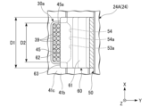
- FIG. 8 and 10 are schematic cross-sectional views of the control device 24. Further, FIG. 9 is a schematic cross-sectional view taken along line IX-IX in FIG. 8. Furthermore, FIG. 11 is a schematic cross-sectional view taken along the line XI-XI in FIG.
- the control device 24 shown in FIGS. 8 and 9 and the control device 24 shown in FIGS. 10 and 11 are installed in indoor units 20 of different models.
- the control device 24 shown in FIGS. 8 and 9 will be referred to as a first control device 24A
- the control device 24 shown in FIGS. 10 and 11 will be referred to as a second control device 24B.
- the first control device 24A and the second control device 24B differ in the number of wires 39 connected to them.
- the number of wires 39 connected to the second control device 24B is greater than the number of wires 39 connected to the first control device 24A.
- the cross-sectional area of all the wirings 39 connected to the first control device 24A and the second control device 24B will be described as being approximately equal.
- the plurality of wirings 39 may include a plurality of types of wirings having different cross-sectional areas.
- the side wall portion 41c covers the housing space A of the electrical component box 30 from below.
- the tip of the side wall portion 41c faces the plate surface 51a of the lid 50.
- the first rib 53a of the lid body 50 overlaps the upper side of the side wall portion 41c.
- the upper surface of the side wall portion 41c and the lower surface of the first rib 53a may be in contact with each other.
- the lid 50 is assembled to the case 40 by overlapping the first rib 53a of the lid 50 with the upper side of the side wall 41c of the case 40. That is, the lid body 50 is assembled to the case 40 by a spigot structure. Therefore, the gap between the case 40 and the lid can be narrowed, and small animals can be prevented from entering the electrical component box 30.
- the notch 45 of the side wall 41c opens on the lid 50 side (ie, on the right side). A part of the inner edge 45a of the notch 45 is located closer to the bottom plate 41a (ie, to the left) than the tip of the first rib 53a. Further, the lid side notch 54 of the first rib 53a is arranged directly above the notch 45.
- the inner edge 45a of the notch 45 and the inner edge 54a of the lid-side notch 54 form a substantially rectangular opening.
- the inner edge 45a of the notch 45 and the inner edge 54a of the lid-side notch 54 constitute a wiring entrance/exit 30a that communicates the storage space A of the electrical component box 30 with the external space.
- the plurality of wirings 39 are arranged inside the notch 45.
- the plurality of wires 39 contact the contact portion 62 of the leaf spring portion 60 .
- the leaf spring section 60 presses the plurality of wires 39 against the inner edge 45a of the cutout section 45. Thereby, the leaf spring section 60 suppresses the wiring 39 from separating from the notch section 45 . Further, the leaf spring portion 60 brings the wirings 39 into contact with each other to minimize the gap between the wirings 39. As a result, the leaf spring portion 60 prevents small animals and dust from entering the electrical component box 30 through the wiring entrance/exit 30a.
- the leaf spring section 60 contacts the plurality of wirings 39 at the contact section 62. Further, the leaf spring portion 60 presses the plurality of wires 39 against the inner edge 45a side of the notch portion 45, and is bent toward the lid 50 (ie, to the right) by the reaction force received from the wires 39.
- the number of wires 39 passing through the wire entrance/exit 30a is relatively small. Therefore, the amount of deflection of the leaf spring section 60 in the first control device 24A is relatively small.
- the second control device 24B shown in FIGS. 10 and 11 the number of wires 39 passing through the wire entrance/exit 30a is larger than in the first control device 24A. Therefore, the amount of deflection of the leaf spring portion 60 in the second control device 24B is larger than that in the first control device 24A.
- the opening area of the notch 45 and the arrangement of the leaf spring part 60 ensure contact between the wiring 39 and the leaf spring part 60 even when the expected number of wirings 39 is the smallest. is set so that Therefore, the leaf spring section 60 is elastically deformed in the elastic section 61 in any model of the control device 24. Thereby, the leaf spring portion 60 presses the plurality of wires 39 against the inner edge 45a of the notch portion 45, thereby suppressing the formation of a large gap at the wire entrance/exit 30a.
- the contact portion 62 of this embodiment is arranged below the side wall portion 41c. Therefore, the contact position between the wiring 39 and the leaf spring portion 60 can be shifted downward with respect to the contact position between the wiring 39 and the inner edge 45a of the notch 45. Thereby, it is possible to prevent force from being concentrated and applied to one portion of the wiring 39 from both the left and right sides.
- the closing plate portion 63 of this embodiment is arranged below the side wall portion 41c. Further, as shown in FIG. 9, the closing plate portion 63 overlaps the notch portion 45 when viewed from the thickness direction of the side wall portion 41c. The closing plate portion 63 closes off a region of the wiring entrance/exit 30a through which the wiring 39 does not pass.
- the width dimension D1 of the closing plate portion 63 is larger than the opening width D2 of the notch portion 45. Therefore, the closing plate portion 63 overlaps the side wall portion 41c on both sides in the width direction.
- the closing plate portion 63 is arranged so as to overlap the side wall portion 41c on one side (lower side) in the thickness direction of the side wall portion 41c.
- the lid-side notch 54 of the first rib 53a overlaps the notch 45 when viewed from the thickness direction of the side wall 41c.
- the lid side notch 54 prevents the wiring 39 from interfering with the first rib 53a above the notch 45 when the number of wirings 39 passing through the notch 45 is large. Therefore, it is possible to prevent a large load from being applied to the wiring 39, such as the wiring 39 being suddenly bent due to interference with the first rib 53a.
- the indoor unit 20 of the present embodiment includes a heat exchanger 22, a blower 23, a control device 24, and a casing that houses the heat exchanger 22, the blower 23, and the control device 24 inside.
- a body 21 is provided.
- the control device 24 includes a first circuit board 31 to which a plurality of wires 39 are connected, and an electrical component box 30 that accommodates the first circuit board 31.
- the electrical component box 30 of the present embodiment includes a side wall portion 41c surrounding the first circuit board 31, a lid body 50 that covers the first circuit board 31, and a leaf spring portion 60 provided on the lid body 50. have The side wall portion 41c is provided with a cutout portion 45 through which the plurality of wiring lines 39 are passed. The leaf spring section 60 presses the plurality of wires 39 against the inner edge 45a of the cutout section 45.
- the plurality of wirings 39 are pressed against the inner edge 45a of the notch 45 by the leaf spring section 60. This can suppress the generation of large gaps between the inner edge 45a of the notch 45 and the plurality of wires 39, between the plurality of wires 39, and between the wires 39 and the leaf spring portion 60. As a result, small animals such as insects and dust can be prevented from entering the housing space A of the electrical component box 30 through the wiring entrance 30a.
- the size of the opening area of the wiring entrance 30a (the same area that allows the passage of a plurality of wirings 39) is adjusted by elastic deformation of the leaf spring portion 60. . As shown in FIGS. 8 and 10, even if the number of wires 39 passing through the notch 45 changes depending on the model, the amount of elastic deformation of the leaf spring section 60 automatically changes and the opening area is adjusted appropriately. . According to the present embodiment, there is no need to separately prepare a member for adjusting the opening area for each model, and it is possible to reduce the number of parts for the indoor units 20 of a plurality of models.
- the plurality of wirings 39 can be positioned within the notch 45 by pressing the plurality of wirings 39 against the inner edge 45a of the notch 45 by the leaf spring section 60. can. According to the present embodiment, it is possible to suppress the wiring 39 from moving due to vibrations, etc., and it is possible to suppress the generation of large gaps between the wiring 39 or between the wiring 39 and the inner edge 45a of the notch 45.
- control device 24 of this embodiment is provided with a plurality of wiring lines 39.
- the wire can be positioned by simply sandwiching the wire between spring-like members.
- a plurality of wires 39 are provided, if the plurality of wires are simply arranged and sandwiched between spring-like members, some of the wires 39 may be There is a risk that some of the wiring may become detached from the sandwiched part due to insufficient support.
- the plurality of wirings 39 by arranging the plurality of wirings 39 in the notch portion 45 and pressing the plurality of wirings 39 against the inner edge 45a by the leaf spring portion 60, the plurality of wirings 39 can be positioned more reliably.
- the leaf spring portion 60 automatically presses the wires 39 against the inner edge 45a of the cutout portion 45, so that the plurality of wires 39 can be easily connected. Can be positioned.
- the side wall portion 41c is a part of the case 40, the wiring 39 can be easily positioned by assembling the lid 50 into the opening of the case 40.
- the leaf spring section 60 includes an elastic section 61, a contact section 62, and a closing plate section 63.
- the elastic portion 61 is fixed to the lid 50 and elastically deforms.
- the contact portion 62 is located at the tip of the elastic portion 61 and contacts the plurality of wirings 39 .
- the closing plate portion 63 extends from the contact portion 62 along the wall surface of the side wall portion 41c.
- the closing plate portion 63 closes at least a portion of the opening of the notch portion 45. Therefore, the wiring 39 is pressed against the inner edge 45a of the notch 45 at the contact portion 62, and the area within the opening of the notch 45 where the wiring 39 is not placed can be easily closed. Thereby, it is possible to suppress the formation of a large gap in the wiring entrance/exit 30a.
- the opening of the notch 45 here means a region surrounded by the inner edge 45a of the notch 45.
- the contact portion 62 of the leaf spring portion 60 is arranged on one side (lower side in this embodiment) of the side wall portion 41c in the thickness direction. Therefore, the inner edge 45a of the side wall portion 41c sandwiching the wiring 39 and the contact portion 62 can be arranged to be shifted in the thickness direction of the side wall portion 41c, and it is possible to suppress stress from being concentrated at one location on the wiring 39. .
- the closing plate portion 63 of the leaf spring portion 60 is arranged on one side (lower side in this embodiment) of the side wall portion 41c in the thickness direction. Further, according to the present embodiment, the width dimension D1 of the closing plate portion 63 is larger than the opening width D2 of the notch portion 45 and overlaps with the side wall portion 41c on both sides in the width direction. Therefore, it is possible to suppress the formation of a gap that becomes an intrusion path for small animals and dust between both ends in the width direction of the leaf spring portion 60 and the inner edge 45a of the notch portion 45.
- the lid 50 is provided with a first rib 53a extending along the side wall 41c.
- the first rib 53a is provided with a lid-side notch 54 that at least partially overlaps the notch 45 when viewed from the thickness direction of the side wall 41c.
- the first rib 53a is provided on the lid 50, a spigot structure between the lid 50 and the case 40 can be realized by the first rib 53a and the side wall portion 41c. Thereby, it is possible to suppress the generation of a large gap between the lid body 50 and the case 40.
- the lid-side notch 54 suppresses interference between the wiring 39 led to the housing space A of the electrical component box 30 and the first rib 53a, thereby suppressing the load on the wiring 39. .
- the lid body 50 has a first lid part 51 and a second lid part 52.
- the first lid portion 51 is integrally molded with the leaf spring portion 60.
- the first lid part 51 is provided with a hole 51h that overlaps the leaf spring part 60 when viewed from the thickness direction of the first lid part 51.
- the second lid part 52 covers the outer surface of the first lid part 51. The second lid portion 52 closes the hole portion 51h.
- the plate of the first lid part 51 can be The first lid portion 51 and the leaf spring portion 60 can be easily molded by setting the thickness direction as the cutting direction of the mold. Further, even when manufacturing the first lid part 51 by press working, the first lid part 51 and the leaf spring part 60 can be easily molded with the plate thickness direction of the first lid part 51 set as the pressing direction.
- the hole 51h is closed by the second lid 52, it is possible to suppress small animals and dust from entering the housing space A side of the electrical component box 30 through the hole 51h. .
- the second lid portion 52 is arranged in the deformation direction of the leaf spring portion 60, as shown in FIG. Therefore, the amount of elastic deformation of the leaf spring section 60 is limited to within the gap size between the closing plate section 63 and the second lid section 52.
- the leaf spring section 60 includes a first elastic section 61a extending from the first lid section 51 in parallel to the plate surface 51a of the first lid section 51, and a first elastic section 61a connected to the first elastic section 61a with respect to the plate surface 51a.
- the second elastic portion 61b is inclined toward the plurality of wiring lines 39.
- the elastic portion 61 when a force is applied to the contact portion 62 from the plurality of wires 39, the second elastic portion 61b that is inclined toward the plurality of wires 39 deforms preferentially than the first elastic portion 61a. Therefore, in the first elastic portion 61a, the amount of deformation in the elastic portion 61 is relatively small. According to the present embodiment, the first elastic portion 61a with a relatively small amount of deformation is arranged at the base of the elastic portion 61 and at the connection portion with the first lid portion 51. Therefore, stress concentration occurring at the boundary between the inner edge of the hole 51h of the first lid part 51 and the elastic part 61 can be reduced, and even if the elastic part 61 is significantly deformed, damage to the root part will not occur. can be suppressed.
- the function of the wiring 39 illustrated in the above-described embodiment is merely an example.
- the wiring 39 may have any function as long as it connects the control device 24 with an internal or external device of the indoor unit.
Landscapes
- Engineering & Computer Science (AREA)
- Chemical & Material Sciences (AREA)
- Combustion & Propulsion (AREA)
- Mechanical Engineering (AREA)
- General Engineering & Computer Science (AREA)
- Air Filters, Heat-Exchange Apparatuses, And Housings Of Air-Conditioning Units (AREA)
Priority Applications (2)
| Application Number | Priority Date | Filing Date | Title |
|---|---|---|---|
| PCT/JP2022/010882 WO2023170913A1 (ja) | 2022-03-11 | 2022-03-11 | 室内機、および空気調和機 |
| JP2024505802A JPWO2023170913A1 (https=) | 2022-03-11 | 2022-03-11 |
Applications Claiming Priority (1)
| Application Number | Priority Date | Filing Date | Title |
|---|---|---|---|
| PCT/JP2022/010882 WO2023170913A1 (ja) | 2022-03-11 | 2022-03-11 | 室内機、および空気調和機 |
Publications (1)
| Publication Number | Publication Date |
|---|---|
| WO2023170913A1 true WO2023170913A1 (ja) | 2023-09-14 |
Family
ID=87936490
Family Applications (1)
| Application Number | Title | Priority Date | Filing Date |
|---|---|---|---|
| PCT/JP2022/010882 Ceased WO2023170913A1 (ja) | 2022-03-11 | 2022-03-11 | 室内機、および空気調和機 |
Country Status (2)
| Country | Link |
|---|---|
| JP (1) | JPWO2023170913A1 (https=) |
| WO (1) | WO2023170913A1 (https=) |
Citations (3)
| Publication number | Priority date | Publication date | Assignee | Title |
|---|---|---|---|---|
| JPS5495152U (https=) * | 1977-12-19 | 1979-07-05 | ||
| JPH0926164A (ja) * | 1995-07-07 | 1997-01-28 | Fujitsu General Ltd | 空気調和機の室外機 |
| JPH1194292A (ja) * | 1997-09-19 | 1999-04-09 | Fujitsu General Ltd | 配線保持装置 |
Family Cites Families (3)
| Publication number | Priority date | Publication date | Assignee | Title |
|---|---|---|---|---|
| JPS5581621U (https=) * | 1978-12-04 | 1980-06-05 | ||
| JP2001332317A (ja) * | 2000-05-22 | 2001-11-30 | Hitachi Ltd | 空気調和機 |
| JP6183603B2 (ja) * | 2013-09-20 | 2017-08-23 | 株式会社富士通ゼネラル | 空気調和機の室内機 |
-
2022
- 2022-03-11 JP JP2024505802A patent/JPWO2023170913A1/ja not_active Ceased
- 2022-03-11 WO PCT/JP2022/010882 patent/WO2023170913A1/ja not_active Ceased
Patent Citations (3)
| Publication number | Priority date | Publication date | Assignee | Title |
|---|---|---|---|---|
| JPS5495152U (https=) * | 1977-12-19 | 1979-07-05 | ||
| JPH0926164A (ja) * | 1995-07-07 | 1997-01-28 | Fujitsu General Ltd | 空気調和機の室外機 |
| JPH1194292A (ja) * | 1997-09-19 | 1999-04-09 | Fujitsu General Ltd | 配線保持装置 |
Also Published As
| Publication number | Publication date |
|---|---|
| JPWO2023170913A1 (https=) | 2023-09-14 |
Similar Documents
| Publication | Publication Date | Title |
|---|---|---|
| JP4520412B2 (ja) | 空気調和機の室外ユニット | |
| US10054320B2 (en) | Indoor device of air conditioner | |
| US20100193164A1 (en) | Outdoor unit of air conditioner | |
| JP5425524B2 (ja) | 室外ユニット | |
| US20100226104A1 (en) | Electrical equipment assembly and outdoor unit of air conditioner disposed with the electrical equipment assembly | |
| JP7012874B2 (ja) | 空気調和機の室外機 | |
| JP5870553B2 (ja) | 空気調和機の室外機 | |
| CN211476125U (zh) | 窗式空调器 | |
| CN111623424A (zh) | 空调装置 | |
| EP2565547A1 (en) | Outdoor unit of air conditioner | |
| US20190113243A1 (en) | Indoor unit for air-conditioning apparatus | |
| WO2023170913A1 (ja) | 室内機、および空気調和機 | |
| JP5549817B2 (ja) | ダクト型空気調和機の室内機 | |
| EP1837609A1 (en) | Outdoor machine of air conditioner | |
| JP7667716B2 (ja) | 空気調和機 | |
| CN113465030A (zh) | 柜式空调室内机和柜式空调 | |
| JP4555712B2 (ja) | 空気調和装置の室外機 | |
| CN203785126U (zh) | 空调机的室外机 | |
| JPWO2018029798A1 (ja) | 空気調和装置の室外機 | |
| JP5557110B2 (ja) | ダクト型空気調和機の室内機 | |
| WO2017037820A1 (ja) | 室外機 | |
| JP7635521B2 (ja) | 空気調和機の室外機 | |
| KR102326299B1 (ko) | 공기조화기의 실내기 | |
| JP5030715B2 (ja) | 空気調和機の室外機 | |
| JP7483336B2 (ja) | ダクト及びそれを備えた電装ユニット |
Legal Events
| Date | Code | Title | Description |
|---|---|---|---|
| 121 | Ep: the epo has been informed by wipo that ep was designated in this application |
Ref document number: 22930894 Country of ref document: EP Kind code of ref document: A1 |
|
| WWE | Wipo information: entry into national phase |
Ref document number: 2024505802 Country of ref document: JP |
|
| NENP | Non-entry into the national phase |
Ref country code: DE |
|
| 122 | Ep: pct application non-entry in european phase |
Ref document number: 22930894 Country of ref document: EP Kind code of ref document: A1 |