WO2023166554A1 - ロータリ圧縮機及び冷凍サイクル装置 - Google Patents
ロータリ圧縮機及び冷凍サイクル装置 Download PDFInfo
- Publication number
- WO2023166554A1 WO2023166554A1 PCT/JP2022/008587 JP2022008587W WO2023166554A1 WO 2023166554 A1 WO2023166554 A1 WO 2023166554A1 JP 2022008587 W JP2022008587 W JP 2022008587W WO 2023166554 A1 WO2023166554 A1 WO 2023166554A1
- Authority
- WO
- WIPO (PCT)
- Prior art keywords
- shaft portion
- rotary compressor
- bearing
- inner peripheral
- peripheral surface
- Prior art date
- Legal status (The legal status is an assumption and is not a legal conclusion. Google has not performed a legal analysis and makes no representation as to the accuracy of the status listed.)
- Ceased
Links
Images



Classifications
-
- F—MECHANICAL ENGINEERING; LIGHTING; HEATING; WEAPONS; BLASTING
- F04—POSITIVE - DISPLACEMENT MACHINES FOR LIQUIDS; PUMPS FOR LIQUIDS OR ELASTIC FLUIDS
- F04C—ROTARY-PISTON, OR OSCILLATING-PISTON, POSITIVE-DISPLACEMENT MACHINES FOR LIQUIDS; ROTARY-PISTON, OR OSCILLATING-PISTON, POSITIVE-DISPLACEMENT PUMPS
- F04C18/00—Rotary-piston pumps specially adapted for elastic fluids
- F04C18/30—Rotary-piston pumps specially adapted for elastic fluids having the characteristics covered by two or more of groups F04C18/02, F04C18/08, F04C18/22, F04C18/24, F04C18/48, or having the characteristics covered by one of these groups together with some other type of movement between co-operating members
- F04C18/34—Rotary-piston pumps specially adapted for elastic fluids having the characteristics covered by two or more of groups F04C18/02, F04C18/08, F04C18/22, F04C18/24, F04C18/48, or having the characteristics covered by one of these groups together with some other type of movement between co-operating members having the movement defined in group F04C18/08 or F04C18/22 and relative reciprocation between the co-operating members
- F04C18/356—Rotary-piston pumps specially adapted for elastic fluids having the characteristics covered by two or more of groups F04C18/02, F04C18/08, F04C18/22, F04C18/24, F04C18/48, or having the characteristics covered by one of these groups together with some other type of movement between co-operating members having the movement defined in group F04C18/08 or F04C18/22 and relative reciprocation between the co-operating members with vanes reciprocating with respect to the outer member
Definitions
- the present disclosure relates to a rotary compressor used in a refrigeration cycle device and a refrigeration cycle device including the rotary compressor.
- a rotary compressor is known as a type of compressor used in refrigeration cycle equipment.
- This rotary compressor includes an electric motor having a rotor, a drive shaft for transmitting the driving force of the electric motor, and a compression mechanism for compressing refrigerant by the driving force of the electric motor transmitted from the drive shaft.
- the drive shaft includes a main shaft portion, a sub shaft portion, and an eccentric shaft portion. The eccentric shaft portion is provided between the main shaft portion and the sub shaft portion, and the central axis is eccentric with respect to the central axes of the main shaft portion and the sub shaft portion.
- the compression mechanism includes a cylinder in which a cylinder chamber in which the eccentric shaft is arranged, an upper bearing that closes one opening of the cylinder chamber, and a lower bearing that closes the other opening of the cylinder chamber. It has In the compression mechanism of a conventional rotary compressor, an upper bearing functioning as a sliding bearing rotatably supports a main shaft, and a lower bearing functioning as a sliding bearing supports a subshaft rotatably. In a compression mechanism of a conventional rotary compressor, an upper bearing and a lower bearing support the load acting on the eccentric shaft portion when compressing the refrigerant in the cylinder chamber (see, for example, Patent Document 1).
- the roughness of the surfaces of the upper and lower bearings facing the drive shaft should be Rzjis 6.3 or less. need to be processed.
- Rzjis indicates ten-point average roughness.
- Rzjis is the sum of the average absolute value of the altitude of the peak and the average value of the average absolute value of the altitude of the valley bottom expressed in units of micrometers.
- the present disclosure has been made in order to solve the above-described problems, and a primary object thereof is to obtain a rotary compressor that can improve productivity more than conventionally.
- a second object of the present disclosure is to obtain a refrigeration cycle apparatus including such a rotary compressor.
- a rotary compressor includes an electric motor having a rotor, a drive shaft fixed to the rotor and transmitting driving force of the electric motor, and the a compression mechanism for compressing the refrigerant by driving force of an electric motor, wherein the drive shaft includes a main shaft portion fixed to the rotor and a sub-shaft having a center shaft coaxially arranged with the center axis of the main shaft portion.
- the compression mechanism a cylinder in which a cylinder chamber is formed penetrating in a central axis direction, and the eccentric shaft portion is disposed in the cylinder chamber; and a bearing that closes one opening of the cylinder chamber and rotatably supports the main shaft portion.
- a closing member that closes the other opening of the cylinder chamber and has a hole into which the sub shaft is inserted, wherein the sub shaft and inner peripheral surfaces of the hole is larger than the gap between the main shaft portion and the inner peripheral surface of the bearing, and the roughness of the inner peripheral surface of the hole is higher than the roughness of the inner peripheral surface of the bearing big.
- a refrigeration cycle device includes a rotary compressor according to the present disclosure, a radiator for releasing heat from refrigerant compressed by the rotary compressor, a pressure reducer for decompressing the refrigerant flowing out from the radiator, an evaporator that evaporates the refrigerant that has flowed out of the decompressor.
- the gap between the sub shaft portion and the inner peripheral surface of the hole of the closing member is larger than the gap between the main shaft portion and the inner peripheral surface of the bearing of the bearing portion.
- the closing member of the rotary compressor according to the present disclosure does not function as a slide bearing. Therefore, in the rotary compressor according to the present disclosure, the roughness of the inner peripheral surface of the hole of the closing member can be made larger than the roughness of the inner peripheral surface of the bearing of the bearing portion. For this reason, the rotary compressor according to the present disclosure can shorten the manufacturing time of the closing member as compared with the manufacturing time of the conventional lower bearing, so that the productivity can be improved more than before.
- FIG. 1 is a longitudinal sectional view of a rotary compressor according to Embodiment 1;
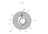
- FIG. FIG. 2 is a cross-sectional view of the compression mechanism of the rotary compressor according to Embodiment 1 cut along the line AA shown in FIG. 1 and observed from above;
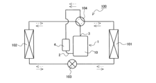
- 1 is a schematic configuration diagram showing a refrigeration cycle apparatus provided with a rotary compressor according to Embodiment 1;
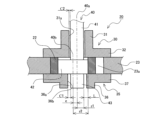
- FIG. 2 is a longitudinal sectional view showing the compression mechanism of the rotary compressor according to Embodiment 1.
- FIG. FIG. 6 is a longitudinal sectional view of a rotary compressor according to Embodiment 2;
- FIG. 6 is a longitudinal sectional view showing a compression mechanism of a rotary compressor according to Embodiment 2;
- FIG. 1 is a longitudinal sectional view of a rotary compressor according to Embodiment 1.
- FIG. FIG. 2 is a cross-sectional view of the compression mechanism of the rotary compressor according to the first embodiment taken along the line AA shown in FIG. 1 and observed from above.
- the main shaft portion 41 of the drive shaft 40 which does not appear on the AA cross section, is indicated by an imaginary chain double-dashed line.
- FIG. 1 is a longitudinal sectional view of a rotary compressor according to Embodiment 1.
- FIG. 2 is a cross-sectional view of the compression mechanism of the rotary compressor according to the first embodiment taken along the line AA shown in FIG. 1 and observed from above.
- the main shaft portion 41 of the drive shaft 40 which does not appear on the AA cross section, is indicated by an imaginary chain double-dashed line.
- FIG. 1 A schematic configuration of the rotary compressor 1 according to the first embodiment will be described below with reference to FIGS. 1 and 2.
- FIG. 1 is a longitudinal sectional view of
- the rotary compressor 1 includes an electric motor 50, a drive shaft 40, and a compression mechanism 20.
- the rotary compressor 1 also includes a closed container 10 in which the electric motor 50, the drive shaft 40, and the compression mechanism 20 are housed.
- the closed container 10 includes an upper container 11 forming the upper portion of the closed container 10 and a lower container 12 forming the lower portion of the closed container 10 .
- a discharge pipe 3 is attached to the upper container 11 . Further, the discharge pipe 3 communicates with the inside of the sealed container 10 .
- the high-pressure refrigerant gas compressed by the compression mechanism 20 is discharged into the sealed container 10 and fills the sealed container 10 . Therefore, the high-pressure refrigerant gas discharged into the sealed container 10 from the compression mechanism 20 flows out of the rotary compressor 1 through the discharge pipe 3 .
- a suction pipe 2 is attached to the lower container 12 . One end of the suction pipe 2 is connected to a suction port 23 d formed in the cylinder 23 of the compression mechanism 20 . That is, the refrigerant flowing into the rotary compressor 1 from the outside of the rotary compressor 1 is guided to the compression mechanism 20 through the suction pipe 2 .
- the bottom of the sealed container 10 serves as an oil reservoir in which refrigerating machine oil is stored.
- the suction muffler 4 is provided at the other end of the suction pipe 2 .
- a mixture of low-pressure refrigerant gas and liquid refrigerant may be sent to the rotary compressor 1 from an external configuration connected to the rotary compressor 1 by piping. Further, when the liquid refrigerant is compressed by the compression mechanism 20, it may cause malfunction of the compression mechanism 20.
- the suction muffler 4 by providing the suction muffler 4 , the liquid refrigerant and the refrigerant gas can be separated by the suction muffler 4 and only the refrigerant gas can be supplied to the compression mechanism 20 .
- the electric motor 50 is arranged above the compression mechanism 20 inside the closed container 10 .
- the electric motor 50 has a stator 51 and a rotor 52 .
- the stator 51 is fixed to the closed container 10 .
- the rotor 52 is rotatably provided inside the stator 51 .
- a rotating magnetic field is formed in the stator 51 by supplying current to the stator 51 from a power source (not shown). This rotating magnetic field acts on the rotor 52, causing the rotor 52 to rotate.
- the drive shaft 40 is fixed to the rotor 52 of the electric motor 50 and transmits the driving force of the electric motor 50 to the compression mechanism 20 .
- the drive shaft 40 includes a substantially cylindrical main shaft portion 41 , a substantially cylindrical eccentric shaft portion 42 , and a substantially cylindrical sub shaft portion 43 .
- the main shaft portion 41 is fixed to the rotor 52 of the electric motor 50 by shrink fitting, press fitting, or the like.
- the secondary shaft portion 43 is arranged so that its central axis is coaxial with the central axis of the main shaft portion 41 .
- the eccentric shaft portion 42 is provided between the main shaft portion 41 and the sub shaft portion 43 .
- the central axis of the eccentric shaft portion 42 is eccentric with respect to the central axis of the main shaft portion 41 .
- An oil pump 29 is provided below the drive shaft 40 .
- the drive shaft 40 is formed with an oil passage 40c that opens at the lower end.
- the oil pump 29 is provided in this oil flow path 40c.
- the oil pump 29 causes the refrigerating machine oil stored in the bottom of the sealed container 10 to flow from the lower opening of the oil flow path 40c into the oil flow path 40c. Pump up.
- the refrigerating machine oil pumped up to the oil passage 40 c is supplied to each sliding portion of the compression mechanism 20 . Thereby, the mechanical lubricating action of the compression mechanism 20 is ensured, and the reliability of the rotary compressor 1 is improved.
- the compression mechanism 20 is arranged below the electric motor 50 inside the sealed container 10 .
- the compression mechanism 20 is connected to the drive shaft 40 and compresses the refrigerant gas by driving force of the electric motor 50 transmitted from the drive shaft 40 .
- the compression mechanism 20 includes a cylinder 23, a bearing portion 30, a closing member 35, a rolling piston 22, and vanes 26. As shown in FIG.
- the cylinder 23 is fixed to the closed container 10 .
- a substantially cylindrical cylinder chamber 23 a is formed in the cylinder 23 so as to penetrate the main shaft portion 41 of the drive shaft 40 in the central axis direction.
- An eccentric shaft portion 42 of the drive shaft 40 is arranged in the cylinder chamber 23a.
- a substantially cylindrical rolling piston 22 is attached to the outer peripheral side of the eccentric shaft portion 42 so as to be slidable with the eccentric shaft portion 42 .
- the rolling piston 22 is also arranged in the cylinder chamber 23a.
- the cylinder 23 is formed with an intake port 23d that communicates with the cylinder chamber 23a.
- the suction pipe 2 is connected to the suction port 23d as described above.
- the cylinder 23 is formed with a vane groove 23c and a back pressure chamber 23b.
- the vane groove 23c is formed in the cylinder 23 so that one end opens to the cylinder chamber 23a.
- Back pressure chamber 23b is formed in cylinder 23 so as to communicate with the other end of vane groove 23c.
- the vane 26 is provided in this vane groove 23c.
- the vane 26 has a substantially rectangular parallelepiped shape. Further, when the vane 26 provided in the vane groove 23c is observed, the shape of the vane 26 is such that the thickness in the width direction of the vane groove 23c, which is the horizontal direction of the paper surface of FIG. is smaller than the length in the radial direction of the cylinder chamber 23a, and smaller than the length in the central axis direction of the cylinder chamber 23a, which is the direction perpendicular to the paper surface of FIG.
- the vane 26 reciprocates in the vane groove 23c in the radial direction of the cylinder chamber 23a. Specifically, the high-pressure refrigerant gas in the sealed container 10 flows into the back pressure chamber 23b. On the other hand, refrigerant gas in the middle of compression exists in the cylinder chamber 23a. Due to the pressure difference between the pressure of the high-pressure refrigerant gas existing in the back pressure chamber 23b acting on the vanes 26 and the pressure of the compressing refrigerant gas existing in the cylinder chamber 23a acting on the vanes 26, the vanes 26 move toward the cylinder chamber. It is pushed towards the center of 23a.
- the end portion of the vane 26 on the side of the cylinder chamber 23 a contacts the outer peripheral portion of the rolling piston 22 .
- the eccentric shaft portion 42 and the rolling piston 22 eccentrically rotate within the cylinder chamber 23a, so that the end of the vane 26 on the cylinder chamber 23a side follows the movement of the rolling piston 22.
- the vane 26 reciprocates in the vane groove 23c in the radial direction of the cylinder chamber 23a.
- the inside of the cylinder chamber 23a is partitioned by the vane 26 to form two working chambers for compressing the refrigerant gas.
- the working chamber sucks the refrigerant gas to be compressed while communicating with the suction port 23d. Further, when the working chamber communicates with a later-described discharge port (not shown) formed in the bearing portion 30, the compressed refrigerant gas is discharged from the discharge port.
- a spring (not shown) is provided in the back pressure chamber 23b to push the vane 26 toward the center of the cylinder chamber 23a.
- the bearing portion 30 closes one opening of the cylinder chamber 23a and supports the main shaft portion 41 of the drive shaft 40 so as to be rotatable. Specifically, the bearing portion 30 closes the opening of the working chamber formed in the cylinder chamber 23a on the main shaft portion 41 side.
- the bearing portion 30 is arranged above the cylinder 23 .
- the bearing portion 30 includes a bearing 31 and a flat plate portion 32 .
- the substantially cylindrical bearing 31 functions as a slide bearing and supports the main shaft portion 41 of the drive shaft 40 so as to be rotatable.
- the flat plate portion 32 has a substantially disk shape and is provided at the lower end portion of the bearing 31 . That is, the flat plate portion 32 is provided at the end portion of the bearing 31 on the cylinder 23 side.
- the bearing portion 30 closes the upper opening of the cylinder chamber 23 a with the flat plate portion 32 .
- the bearing portion 30 has a substantially inverted T shape when viewed from the side.
- the flat plate portion 32 of the bearing portion 30 is formed with a discharge port (not shown) that communicates between the inside of the cylinder chamber 23a and the outside of the compression mechanism 20. As shown in FIG. Further, the flat plate portion 32 of the bearing portion 30 is provided with a discharge valve that covers the discharge port in an openable and closable manner. The discharge valve closes the discharge port until the refrigerant gas compressed in the working chamber formed in the cylinder chamber 23a reaches a specified pressure. When the refrigerant gas compressed in the working chamber formed in the cylinder chamber 23a reaches a specified pressure or higher, the discharge valve opens the discharge port and discharges the refrigerant gas compressed in the working chamber to the outside of the compression mechanism 20. . That is, the discharge valve controls the discharge timing of the refrigerant gas compressed in the working chamber formed in the cylinder chamber 23a.
- the closing member 35 closes the other opening of the cylinder chamber 23a and has a hole 36a into which the sub shaft portion 43 of the drive shaft 40 is inserted. Specifically, the closing member 35 closes the opening of the working chamber formed in the cylinder chamber 23a on the sub shaft portion 43 side. In Embodiment 1, the closing member 35 is arranged below the cylinder 23 .
- the closing member 35 has a cylindrical portion 36 and a flat plate portion 37 .
- a through hole 36 a is formed in the cylindrical portion 36 .
- a secondary shaft portion 43 of the drive shaft 40 is inserted into the hole 36a.
- the flat plate portion 37 has a substantially disk shape and is provided at the upper end portion of the cylindrical portion 36 . That is, the flat plate portion 37 is provided at the end portion of the cylindrical portion 36 on the cylinder 23 side.
- the closing member 35 closes the lower opening of the cylinder chamber 23 a with the flat plate portion 37 . As shown in FIG. 1, the closing member 35 has a substantially T-shape when viewed from the side.
- the hole 36a does not have to be a through hole as long as the sub shaft portion 43 can be inserted therethrough, and at least the cylinder 23 side should be open.
- the rotary compressor 1 according to Embodiment 1 is provided with a discharge muffler 27 .
- the discharge muffler 27 is provided outside the bearing portion 30 , that is, on the electric motor 50 side so as to cover the bearing portion 30 .
- the discharge muffler 27 is formed with an outflow hole (not shown) that communicates the space formed between the discharge muffler 27 and the bearing portion 30 with the inside of the sealed container 10 .
- Refrigerant gas compressed in the working chamber formed in the cylinder chamber 23 a is once discharged into the space formed between the discharge muffler 27 and the bearing portion 30 .
- Refrigerant gas discharged into the space formed between the discharge muffler 27 and the bearing portion 30 flows out into the sealed container 10 through the outflow holes formed in the discharge muffler 27 .
- the rotary compressor 1 configured in this way operates as follows.
- the drive shaft 40 fixed to the rotor 52 also rotates.
- the eccentric shaft portion 42 of the drive shaft 40 and the rolling piston 22 attached to the eccentric shaft portion 42 eccentrically rotate within the cylinder chamber 23 a of the cylinder 23 .
- the volume of the working chamber formed in the cylinder chamber 23a repeats increase and decrease as the drive shaft 40 rotates.
- the working chamber communicates with the suction port 23d, and low-pressure refrigerant gas is sucked into the working chamber.
- the volume of the working chamber decreases.
- the refrigerant gas in the working chamber is compressed.
- the discharge valve is pushed up by the refrigerant gas to open the discharge port.
- the high-pressure refrigerant gas compressed in the working chamber is discharged from the working chamber through the discharge port into the space formed between the discharge muffler 27 and the bearing portion 30 .
- the high-pressure refrigerant gas that has flowed out into the sealed container 10 passes through flow paths formed between the stator 51 and the rotor 52 of the electric motor 50 and on the outer peripheral side of the stator 51, and flows upward from the electric motor 50. flow to The high-pressure refrigerant gas that reaches above the electric motor 50 flows out of the rotary compressor 1 through the discharge pipe 3 .
- FIG. 3 is a schematic configuration diagram showing a refrigeration cycle apparatus provided with a rotary compressor according to Embodiment 1.
- the refrigerating cycle device 100 includes the rotary compressor 1 according to Embodiment 1, a radiator for releasing heat from the refrigerant compressed by the rotary compressor 1, and a pressure reducing device such as an electric expansion valve for reducing the pressure of the refrigerant flowing out from the radiator. and an evaporator in which the refrigerant flowing out of the pressure reducer 103 evaporates.
- the refrigeration cycle device 100 is used for various purposes such as a hot water supply system and a refrigeration system.
- FIG. 3 shows an example in which the refrigeration cycle device 100 is used as an air conditioner. Therefore, the refrigeration cycle apparatus 100 shown in FIG. 3 includes an indoor heat exchanger 102 that functions as a radiator during heating operation, and an outdoor heat exchanger 101 that functions as an evaporator during heating operation.
- the refrigeration cycle device 100 shown in FIG. 3 is also capable of cooling operation. For this reason, the refrigeration cycle device 100 includes a four-way switching valve 104 .
- the four-way switching valve 104 switches the heat exchanger connected to the discharge pipe 3, which is the refrigerant discharge port of the rotary compressor 1, and the heat exchanger connected to the suction muffler 4, which is the refrigerant suction port of the rotary compressor 1. It is to switch the vessel.
- the indoor heat exchanger 102 functions as an evaporator
- the outdoor heat exchanger 101 functions as a radiator.
- the indoor heat exchanger 102 is installed in an indoor device.
- the rotary compressor 1, the four-way switching valve 104, the outdoor heat exchanger 101, and the pressure reducer 103 are mounted on an outdoor device.
- the refrigeration cycle device 100 uses R407C refrigerant, R410A refrigerant, R32 refrigerant, or the like. The operation of the refrigeration cycle apparatus 100 during heating operation and cooling operation will be described below.
- the four-way switching valve 104 switches to the flow path indicated by the solid line in FIG.
- the discharge pipe 3 of the rotary compressor 1 is connected to the indoor heat exchanger 102
- the suction muffler 4 of the rotary compressor 1 is connected to the outdoor heat exchanger 101 .
- the indoor heat exchanger 102 functions as a radiator
- the outdoor heat exchanger 101 functions as an evaporator.
- this high-temperature, high-pressure refrigerant gas flows into the indoor heat exchanger 102 .
- the high-temperature and high-pressure refrigerant gas that has flowed into the indoor heat exchanger 102 condenses while radiating heat to the indoor air, and flows out of the indoor-side heat exchanger 102 as a high-pressure liquid refrigerant. At this time, the indoor air is heated.
- refrigerant such as carbon dioxide refrigerant
- the radiator may be referred to as a condenser.
- the high-pressure liquid refrigerant that has flowed out of the indoor-side heat exchanger 102 flows into the pressure reducer 103 .
- the high-pressure liquid refrigerant that has flowed into the pressure reducer 103 is decompressed by the pressure reducer 103 to become a low-temperature, low-pressure gas-liquid two-phase refrigerant, and flows out of the pressure reducer 103 .
- the low-temperature, low-pressure gas-liquid two-phase refrigerant that has flowed out of the pressure reducer 103 flows into the outdoor heat exchanger 101 .
- the low-temperature, low-pressure gas-liquid two-phase refrigerant that has flowed into the outdoor heat exchanger 101 absorbs heat from outdoor air, evaporates, and flows out of the outdoor heat exchanger 101 as a low-pressure refrigerant gas or gas-liquid two-phase refrigerant. .
- the low-pressure refrigerant gas or gas-liquid two-phase refrigerant that has flowed out of the outdoor heat exchanger 101 is sucked into the suction muffler 4 of the rotary compressor 1 .
- low-pressure refrigerant gas is compressed by the compression mechanism 20 of the rotary compressor 1 to become high-temperature and high-pressure refrigerant gas.
- This high-temperature, high-pressure refrigerant gas is discharged from the rotary compressor 1 again. That is, when the refrigeration cycle device 100 performs heating operation, the refrigerant circulates as indicated by the solid line arrows in FIG.
- the four-way switching valve 104 switches to the flow path indicated by the dashed line in FIG.
- the discharge pipe 3 of the rotary compressor 1 is connected to the outdoor heat exchanger 101
- the suction muffler 4 of the rotary compressor 1 is connected to the indoor heat exchanger 102 .
- the outdoor heat exchanger 101 functions as a radiator
- the indoor heat exchanger 102 functions as an evaporator.
- this high-temperature, high-pressure refrigerant gas flows into the outdoor heat exchanger 101 .
- the high-temperature and high-pressure refrigerant gas that has flowed into the outdoor heat exchanger 101 condenses while radiating heat to the outdoor air, and flows out of the outdoor heat exchanger 101 as a high-pressure liquid refrigerant.
- the high-pressure liquid refrigerant that has flowed out of the outdoor heat exchanger 101 flows into the pressure reducer 103 .
- the high-pressure liquid refrigerant that has flowed into the pressure reducer 103 is decompressed by the pressure reducer 103 to become a low-temperature, low-pressure gas-liquid two-phase refrigerant, and flows out of the pressure reducer 103 .
- the low-temperature, low-pressure gas-liquid two-phase refrigerant that has flowed out of the pressure reducer 103 flows into the indoor-side heat exchanger 102 .
- the low-temperature, low-pressure gas-liquid two-phase refrigerant that has flowed into the indoor heat exchanger 102 absorbs heat from indoor air, evaporates, and flows out of the indoor-side heat exchanger 102 as a low-pressure refrigerant gas or gas-liquid two-phase refrigerant. . At this time, the indoor air is cooled. The low-pressure refrigerant gas or gas-liquid two-phase refrigerant that has flowed out of the indoor heat exchanger 102 is sucked into the suction muffler 4 of the rotary compressor 1 .
- FIG. 4 is a longitudinal sectional view showing the compression mechanism of the rotary compressor according to Embodiment 1.
- FIG. A central axis 40 a shown in FIG. 4 indicates the central axis of the main shaft portion 41 and the sub shaft portion 43 of the drive shaft 40 .
- a central axis 40 b shown in FIG. 4 indicates the central axis of the eccentric shaft portion 42 of the drive shaft 40 . Details of the compression mechanism 20 of the rotary compressor 1 according to the first embodiment will be described below with reference to FIG.
- the bearing 31 of the bearing portion 30 functions as a slide bearing and supports the main shaft portion 41 of the drive shaft 40 so as to be rotatable.
- the blocking member 35 into which the secondary shaft portion 43 of the drive shaft 40 is inserted does not function as a sliding bearing that rotatably supports the secondary shaft portion 43 . Therefore, the gap C1 between the auxiliary shaft portion 43 of the drive shaft 40 and the inner peripheral surface 36b of the hole 36a of the closing member 35 is the main shaft portion 41 of the drive shaft 40 and the inner peripheral surface 31a of the bearing 31 of the bearing portion 30. is larger than the gap C2 between.
- the clearance C1 between the sub shaft portion 43 of the drive shaft 40 and the inner peripheral surface 36b of the hole 36a of the closing member 35 is 0.5 mm.
- the gap C2 between the main shaft portion 41 of the drive shaft 40 and the inner peripheral surface 31a of the bearing 31 of the bearing portion 30 is 5 ⁇ m to 20 ⁇ m. ing.
- the roughness of the inner peripheral surface 36b of the hole 36a of the closing member 35 can be made larger than the roughness of the inner peripheral surface 31a of the bearing 31 of the bearing portion 30.
- the roughness of the inner peripheral surface 31a of the bearing 31 of the bearing portion 30 is Rzjis 6.3 or less so that the bearing 31 functions as a sliding bearing.
- the inner peripheral surface 36b of the hole 36a of the closing member 35 does not come into contact with the secondary shaft portion 43 of the drive shaft 40. As shown in FIG. Therefore, the roughness of the inner peripheral surface 36b of the hole 36a of the closing member 35 can be made larger than Rzjis 6.3.
- the roughness of the inner peripheral surface 36b of the hole 36a of the closing member 35 is, for example, Rzjis 400 or less.
- Rzjis indicates ten-point average roughness.
- Rzjis is the sum of the average absolute value of the altitude of the peak and the average value of the average absolute value of the altitude of the valley bottom expressed in units of micrometers.
- a conventional rotary compressor was provided with a lower bearing instead of the closing member 35 of the rotary compressor 1 according to the first embodiment.
- the lower bearing functions as a slide bearing and rotatably supports the sub-shaft portion of the drive shaft. For this reason, the roughness of the surface of the lower bearing facing the countershaft portion had to be processed to Rzjis 6.3 or less. Further, it takes a long time to process the surface of the lower bearing that faces the counter shaft to Rzjis 6.3 or less. Therefore, in the conventional rotary compressor, the manufacturing time of the lower bearing is restricted, and it is difficult to improve the productivity.
- the clearance C1 between the subshaft portion 43 and the inner peripheral surface 36b of the hole 36a of the closing member 35 is It is larger than the gap C2 with the inner peripheral surface 31a. Therefore, the closing member 35 of the rotary compressor 1 according to Embodiment 1 does not function as a sliding bearing. Therefore, in the rotary compressor 1 according to Embodiment 1, the roughness of the inner peripheral surface 36b of the hole 36a of the closing member 35 can be made larger than the roughness of the inner peripheral surface 31a of the bearing 31 of the bearing portion 30. . Therefore, in the rotary compressor 1 according to Embodiment 1, the production time of the closing member 35 can be shortened as compared with the production time of the conventional lower bearing, so that the productivity can be improved more than the conventional one.
- the rotary compressor 1 according to Embodiment 1 includes only the bearing portion 30 as a sliding bearing that rotatably supports the drive shaft 40 . If the roughness of the surface of the slide bearing facing the drive shaft varies from product to product, it affects the efficiency and reliability of the rotary compressor.
- the number of sliding bearings that rotatably support the drive shaft 40 can be reduced as compared with a conventional rotary compressor. For this reason, the rotary compressor 1 according to Embodiment 1 can suppress deterioration in efficiency and reliability due to variations in the surface roughness of the slide bearing from product to product, compared to the conventional rotary compressor 1 .
- the rotary compressor 1 acts on the eccentric shaft portion 42 when compressing the refrigerant. It should be added here that the load can be sufficiently supported.
- the roughness of the inner peripheral surface 36b of the hole 36a of the closing member 35 is larger than that of the Rzjis 25. If the inner peripheral surface 36b of the hole 36a of the blocking member 35 is to be processed to have a roughness greater than Rzjis 6.3 and Rzjis 25 or less, a medium finishing process is performed by polishing. On the other hand, when the inner peripheral surface 36b of the hole 36a of the closing member 35 is processed to have a roughness greater than Rzjis25, rough finishing by grinding may be performed. Therefore, by making the roughness of the inner peripheral surface 36b of the hole 36a of the blocking member 35 larger than that of the Rzjis 25, the manufacturing time of the blocking member 35 can be shortened, and the productivity of the rotary compressor 1 can be further improved. can.
- the roughness of the inner peripheral surface 36b of the hole 36a of the closing member 35 is larger than that of Rzjis100.
- the inner peripheral surface 36b of the blocking member 35 may be the skin of the material.
- the inner peripheral surface 36b of the closing member 35 may be left as cast. Therefore, by making the roughness of the inner peripheral surface 36b of the hole 36a of the blocking member 35 larger than that of Rzjis 100, the manufacturing time of the blocking member 35 can be further shortened, and the productivity of the rotary compressor 1 can be further improved. can.
- the eccentric shaft portion 42 of the drive shaft 40 and the closing member 35 are observed in the direction of the central axis 40b of the eccentric shaft portion 42, the entire outer peripheral portion of the eccentric shaft portion 42 extends over the entire outer circumference of the hole 36a of the closing member 35. It is preferable that it overlaps with the part. In other words, when the eccentric shaft portion 42 of the drive shaft 40 and the closing member 35 are observed from above, the entire outer peripheral portion of the eccentric shaft portion 42 overlaps the outer peripheral portion of the hole 36 a of the closing member 35 . preferable. By adopting this configuration, the eccentric shaft portion 42 can be supported from below by the closing member 35 . Therefore, by adopting this configuration, the reliability of the rotary compressor 1 is improved.
- This configuration can be realized by setting the gap C1 between the secondary shaft portion 43 of the drive shaft 40 and the inner peripheral surface 36b of the hole 36a of the closing member 35 as follows.
- FIG. 4 shows a state in which the central axis 40b of the eccentric shaft portion 42 is the most left side of the paper surface. That is, FIG. 4 shows a state in which the eccentric shaft portion 42 is most eccentric on the left side of the drawing. In the eccentric shaft portion 42 in this state, the portion on the anti-eccentric side of the eccentric shaft portion 42 is the right end portion of the eccentric shaft portion 42 shown in FIG.
- the eccentricity e of the eccentric shaft portion 42 is the distance between the central axis 40 a of the main shaft portion 41 and the sub shaft portion 43 and the central axis 40 b of the eccentric shaft portion 42 . Further, the distance between the part of the eccentric shaft portion 42 on the anti-eccentric side and the central axis 40a of the secondary shaft portion 43 is a value obtained by subtracting the eccentricity e from the radius r2 of the eccentric shaft portion 42.
- the main shaft portion 41 and the sub shaft portion 43 have the same diameter.
- the diameter of the inner peripheral surface 36b of the closing member 35 is made larger than the diameter of the inner peripheral surface 31a of the bearing portion 30
- the gap between the sub-shaft portion 43 and the inner peripheral surface 36b of the hole 36a of the closing member 35 is increased. is made larger than the gap C2 between the main shaft portion 41 and the inner peripheral surface 31 a of the bearing 31 .
- the configuration in which the clearance C1 is larger than the clearance C2 is not limited to this configuration.
- the diameter of the inner peripheral surface 36b of the closing member 35 and the diameter of the inner peripheral surface 31a of the bearing portion 30 may be the same, and the diameter of the sub shaft portion 43 may be smaller than the diameter of the main shaft portion 41. Even with such a configuration, the gap C1 can be made larger than the gap C2.
- the rotary compressor 1 includes the electric motor 50 having the rotor 52 , the drive shaft 40 fixed to the rotor 52 and transmitting the driving force of the electric motor 50 , and the drive shaft 40 connected to the drive shaft 40 . , and a compression mechanism 20 that compresses the refrigerant by the driving force of the electric motor 50 transmitted from the drive shaft 40 .
- the drive shaft 40 includes a main shaft portion 41 fixed to the rotor 52 , a sub-shaft portion 43 whose center axis is coaxial with the center axis of the main shaft portion 41 , and the main shaft portion 41 and the sub-shaft portion 43 .
- the compression mechanism 20 is formed with a cylinder chamber 23a penetrating in the central axis direction of the main shaft portion 41, and the eccentric shaft portion 42 closes one opening of the cylinder 23 arranged in the cylinder chamber 23a and the cylinder chamber 23a.
- a bearing portion 30 having a bearing 31 for rotatably supporting the main shaft portion 41, and a closing member 35 which closes the other opening of the cylinder chamber 23a and has a hole 36a into which the sub shaft portion 43 is inserted. and have.
- the gap C1 between the sub shaft portion 43 and the inner peripheral surface 36b of the hole 36a is the gap between the main shaft portion 41 and the inner peripheral surface 31a of the bearing 31. It is larger than the gap C2, and the roughness of the inner peripheral surface 36b of the hole 36a is larger than the roughness of the inner peripheral surface 31a of the bearing 31. As shown in FIG.
- the time required to manufacture the closing member 35 can be shortened compared to the time required to manufacture the conventional lower bearing, so productivity can be improved more than before.
- the auxiliary shaft portion 43 of the drive shaft 40 is rotatably supported by the closing member 35 without contacting the inner peripheral surface 36b of the hole 36a of the closing member 35. It has not been. For this reason, those skilled in the art may think that the secondary shaft portion 43 of the drive shaft 40 is unnecessary in the rotary compressor 1 according to the first embodiment. However, when the sub-shaft portion 43 is removed from the drive shaft 40, compared to the case where the drive shaft 40 is provided with the sub-shaft portion 43, the position of the lower opening of the oil passage 40c formed in the drive shaft 40 is shifted. , higher.
- the rotary compressor 1 includes the sub shaft portion 43 on the drive shaft 40 .
- Embodiment 2 By configuring the closing member 35 as in the second embodiment, in addition to the effects of the first embodiment, the effect of suppressing the generation of vibration and noise of the rotary compressor 1 is also obtained. Matters not specifically mentioned in the second embodiment are the same as those in the first embodiment. In addition, in the second embodiment, the same reference numerals as in the first embodiment are assigned to the structures that perform the same functions as the structures shown in the first embodiment.
- FIG. 5 is a longitudinal sectional view of a rotary compressor according to the second embodiment.
- FIG. 6 is a longitudinal sectional view showing the compression mechanism of the rotary compressor according to the second embodiment.
- the closing member 35 according to the second embodiment does not have the cylindrical portion 36 of the closing member 35 shown in the first embodiment.
- the hole 36 a is formed in the substantially disk-shaped flat plate portion 37 .
- the closing member 35 according to Embodiment 2 has a flat plate shape.
- the blocking member 35 according to the second embodiment has a length in the vertical direction corresponding to the downward projection length of the cylindrical portion 36 from the flat plate portion 37, compared with the blocking member 35 shown in the first embodiment. is getting shorter.
- the closing member 35 which is the lower end of the compression mechanism 20
- the lower surface of the flat plate portion 37 can be arranged at the lower end of the cylindrical portion 36 of the closing member 35, which is the lower end of the compression mechanism 20 shown in the first embodiment. That is, in the rotary compressor 1 according to Embodiment 2, compared with the rotary compressor 1 shown in Embodiment 1, the arrangement positions of the electric motor 50, the drive shaft 40, and the compression mechanism 20 in the sealed container 10 are It can be lowered by the length of the cylindrical portion 36 projecting downward from the flat plate portion 37 .
- the vertical length of the secondary shaft portion 43 of the drive shaft 40 according to the second embodiment can be shortened by the length of the cylindrical portion 36 projecting downward from the flat plate portion 37 . Even if the length of the secondary shaft portion 43 in the vertical direction is shortened in this way, the position of the lower opening of the oil passage 40c remains the same as in the first embodiment. Because you can.
- the vertical length of the secondary shaft portion 43 is shortened so that the lower end of the secondary shaft portion 43 is positioned substantially at the same position as the lower surface of the flat plate portion 37 of the closing member 35 .
- the arrangement positions of the electric motor 50, the drive shaft 40, and the compression mechanism 20 in the sealed container 10 are changed as compared with the rotary compressor 1 shown in the first embodiment. , can be lowered by the length of the cylindrical portion 36 projecting downward from the flat plate portion 37 . Therefore, in the rotary compressor 1 according to the second embodiment, compared with the rotary compressor 1 shown in the first embodiment, the length of the sealed container 10 in the vertical direction is reduced from the flat plate portion 37 to the cylindrical portion 36. It can be shortened by the length that protruded downward.
- the vertical length of the rotary compressor 1 according to the second embodiment is the length of the cylindrical portion 36 protruding downward from the flat plate portion 37.
- the rotary compressor 1 according to the second embodiment has a lower center of gravity than the rotary compressor 1 shown in the first embodiment. Therefore, the rotary compressor 1 according to the second embodiment can obtain the same effect as the rotary compressor 1 shown in the first embodiment, and also has more vibration and vibration than the rotary compressor 1 shown in the first embodiment. An effect of being able to suppress the generation of noise is also obtained.
Landscapes
- Engineering & Computer Science (AREA)
- Mechanical Engineering (AREA)
- General Engineering & Computer Science (AREA)
- Applications Or Details Of Rotary Compressors (AREA)
Abstract
本開示に係るロータリ圧縮機の圧縮機構は、シリンダ室が形成され、駆動軸の偏心軸部が該シリンダ室に配置されたシリンダと、前記シリンダ室の一方の開口部を閉塞すると共に、前記駆動軸の主軸部を回転自在に支持する軸受を有する軸受部と、前記シリンダ室の他方の開口部を閉塞すると共に、前記駆動軸の副軸部が挿入された穴が形成された閉塞部材と、を備えている。そして、本開示に係るロータリ圧縮機は、前記副軸部と前記穴の内周面との間の隙間が前記主軸部と前記軸受の内周面との間の隙間よりも大きくなっており、前記穴の内周面の粗度が前記軸受の内周面の粗度よりも大きい。
Description
本開示は、冷凍サイクル装置に用いられるロータリ圧縮機、及び該ロータリ圧縮機を備えた冷凍サイクル装置に関する。
従来、冷凍サイクル装置に用いられる圧縮機の一種として、ロータリ圧縮機が知られている。このロータリ圧縮機は、回転子を有する電動機と、電動機の駆動力を伝達する駆動軸と、駆動軸から伝達された電動機の駆動力によって冷媒を圧縮する圧縮機構とを備えている。また、駆動軸は、主軸部と、副軸部と、偏心軸部とを備えている。偏心軸部は、主軸部と副軸部との間に設けられ、中心軸が主軸部及び副軸部の中心軸に対して偏心している。また、圧縮機構は、偏心軸部の配置されたシリンダ室が形成されているシリンダと、シリンダ室の一方の開口部を閉塞する上軸受と、シリンダ室の他方の開口部を閉塞する下軸受とを備えている。また、従来のロータリ圧縮機の圧縮機構は、滑り軸受として機能する上軸受で主軸部を回転自在に支持し、滑り軸受として機能する下軸受で副軸部を回転自在に支持している。そして、従来のロータリ圧縮機の圧縮機構は、シリンダ室で冷媒を圧縮する際に偏心軸部に作用する荷重を、上軸受及び下軸受で支持する(例えば、特許文献1参照)。
JIS-B1582-1976の付表1等を参照すると、上軸受及び下軸受を滑り軸受として機能させるためには、上軸受及び下軸受における駆動軸と対向する面の粗度を、Rzjis6.3以下に加工する必要がある。なお、Rzjisは、十点平均粗さを示す。Rzjisを求める際、まず、面の粗さ曲線から、その平均線の方向に基準長さだけを抜き取る。また、抜き取り部分の平均線から縦倍率の方向に測定した、最も高い山頂から5番目までの山頂の標高の絶対値の平均値を求める。また、抜き取り部分の平均線から縦倍率の方向に測定した、最も低い谷底から5番目までの谷底の標高の絶対値の平均値を求める。そして、山頂の標高の絶対値の平均値と谷底の標高の絶対値の平均値との和をマイクロメートルの単位で表したものが、Rzjisとなる。
面の粗度をRzjis6.3に加工するには、時間がかかる。すなわち、上軸受及び下軸受の製作には、時間がかかる。このため、従来のロータリ圧縮機は、上軸受及び下軸受の製作時間が制約となり、生産性を向上させることが難しいという課題があった。
本開示は、上述の課題を解決するためになされたものであり、生産性を従来よりも向上させることができるロータリ圧縮機を得ることを第1の目的とする。また、本開示は、このようなロータリ圧縮機を備えた冷凍サイクル装置を得ることを第2の目的とする。
本開示に係るロータリ圧縮機は、回転子を有する電動機と、前記回転子に固定され、前記電動機の駆動力を伝達する駆動軸と、前記駆動軸に接続され、前記駆動軸から伝達された前記電動機の駆動力によって冷媒を圧縮する圧縮機構と、を備え、前記駆動軸は、前記回転子に固定された主軸部と、該主軸部の中心軸と同軸上に中心軸が配置された副軸部と、前記主軸部と前記副軸部との間に設けられ、中心軸が前記主軸部の中心軸に対して偏心している偏心軸部と、を備え、前記圧縮機構は、前記主軸部の中心軸方向に貫通するシリンダ室が形成され、前記偏心軸部が該シリンダ室に配置されたシリンダと、前記シリンダ室の一方の開口部を閉塞すると共に、前記主軸部を回転自在に支持する軸受を有する軸受部と、前記シリンダ室の他方の開口部を閉塞すると共に、前記副軸部が挿入された穴が形成された閉塞部材と、を備え、前記副軸部と前記穴の内周面との間の隙間が、前記主軸部と前記軸受の内周面との間の隙間よりも大きくなっており、前記穴の内周面の粗度が前記軸受の内周面の粗度よりも大きい。
また、本開示に係る冷凍サイクル装置は、本開示に係るロータリ圧縮機と、前記ロータリ圧縮機で圧縮された冷媒が放熱する放熱器と、前記放熱器から流出した冷媒を減圧する減圧器と、前記減圧器から流出した冷媒が蒸発する蒸発器と、を備えている。
本開示に係るロータリ圧縮機においては、副軸部と閉塞部材の穴の内周面との間の隙間が、主軸部と軸受部の軸受の内周面との間の隙間よりも大きくなっている。このため、本開示に係るロータリ圧縮機の閉塞部材は、滑り軸受としての機能を有しない。したがって、本開示に係るロータリ圧縮機においては、閉塞部材の穴の内周面の粗度を軸受部の軸受の内周面の粗度よりも大きくできる。このため、本開示に係るロータリ圧縮機は、閉塞部材の製作時間を従来の下軸受の製作時間よりも短縮できるので、生産性を従来よりも向上させることができる。
以下の各実施の形態において、本開示に係るロータリ圧縮機の一例について説明する。なお、以下の各実施の形態では、1シリンダ型で密閉型のロータリ圧縮機を例に、本開示に係るロータリ圧縮機の一例を説明する。
実施の形態1.
図1は、本実施の形態1に係るロータリ圧縮機の縦断面図である。また、図2は、図1に示すA-A断面で本実施の形態1に係るロータリ圧縮機の圧縮機構を切断し、該圧縮機構を上方から観察した断面図である。なお、図2では、A-A断面では表れない駆動軸40の主軸部41を、想像線である二点鎖線で示している。
以下、図1及び図2を用いて、本実施の形態1に係るロータリ圧縮機1の概略構成について説明する。
図1は、本実施の形態1に係るロータリ圧縮機の縦断面図である。また、図2は、図1に示すA-A断面で本実施の形態1に係るロータリ圧縮機の圧縮機構を切断し、該圧縮機構を上方から観察した断面図である。なお、図2では、A-A断面では表れない駆動軸40の主軸部41を、想像線である二点鎖線で示している。
以下、図1及び図2を用いて、本実施の形態1に係るロータリ圧縮機1の概略構成について説明する。
ロータリ圧縮機1は、電動機50、駆動軸40、及び圧縮機構20を備えている。また、ロータリ圧縮機1は、電動機50、駆動軸40、及び圧縮機構20が収納された密閉容器10を備えている。
密閉容器10は、該密閉容器10の上部を構成する上部容器11と、該密閉容器10の下部を構成する下部容器12とを備えている。上部容器11には、吐出管3が取り付けられている。また、吐出管3は、密閉容器10の内部に連通している。後述のように、圧縮機構20で圧縮された高圧な冷媒ガスは、密閉容器10の内部に吐出され、密閉容器10内を満たす。このため、圧縮機構20から密閉容器10内に吐出された高圧な冷媒ガスは、吐出管3を通って、ロータリ圧縮機1の外部へ流出することとなる。下部容器12には、吸入管2が取り付けられている。また、吸入管2の一方の端部は、圧縮機構20のシリンダ23に形成された吸入口23dに接続されている。すなわち、ロータリ圧縮機1の外部からロータリ圧縮機1の内部へ流入する冷媒は、吸入管2を通って圧縮機構20へ導かれる。この密閉容器10の底部は、冷凍機油が貯留される油溜めとなっている。
なお、本実施の形態1では、吸入管2の他方の端部に、吸入マフラ4が設けられている。ロータリ圧縮機1には、該ロータリ圧縮機1と配管接続された外部の構成から、低圧の冷媒ガスと液冷媒とが混在して送られてくる場合がある。また、液冷媒が圧縮機構20で圧縮されると、圧縮機構20の動作不良の原因となる場合がある。しかしながら、吸入マフラ4を設けることにより、吸入マフラ4で液冷媒と冷媒ガスを分離し、冷媒ガスのみを圧縮機構20に供給することができる。
電動機50は、密閉容器10内において、圧縮機構20の上方に配置されている。電動機50は、固定子51及び回転子52を備えている。固定子51は、密閉容器10に固定されている。回転子52は、固定子51の内周側に回転自在に設けられている。図示せぬ電源から固定子51に電流を供給することにより、固定子51に回転磁界が形成される。この回転磁界が回転子52に作用し、回転子52が回転する。
駆動軸40は、電動機50の回転子52に固定され、電動機50の駆動力を圧縮機構20に伝達するものである。駆動軸40は、略円柱形状の主軸部41、略円柱形状の偏心軸部42、及び略円柱形状の副軸部43を備えている。主軸部41は、焼嵌め又は圧入等により、電動機50の回転子52に固定されている。副軸部43は、中心軸が主軸部41の中心軸と同軸上に配置されている。偏心軸部42は、主軸部41と副軸部43との間に設けられている。偏心軸部42は、中心軸が主軸部41の中心軸に対して偏心している。
また、駆動軸40の下部には、オイルポンプ29が設けられている。具体的には、駆動軸40には、下端に開口する油流路40cが形成されている。オイルポンプ29は、この油流路40cに設けられている。電動機50の回転子52と共に駆動軸40が回転することにより、オイルポンプ29は、密閉容器10の底部に貯留された冷凍機油を、油流路40cの下部の開口部から該油流路40cに汲み上げる。そして、油流路40cに汲み上げられた冷凍機油は、圧縮機構20の各摺動部へ供給される。これにより、圧縮機構20の機械的潤滑作用が確保され、ロータリ圧縮機1の信頼性が向上する。
圧縮機構20は、密閉容器10内において、電動機50の下方に配置されている。圧縮機構20は、駆動軸40に接続され、駆動軸40から伝達された電動機50の駆動力によって冷媒ガスを圧縮するものである。図1及び図2に示すように、圧縮機構20は、シリンダ23、軸受部30、閉塞部材35、ローリングピストン22、及びベーン26を備えている。
シリンダ23は、密閉容器10に固定されている。シリンダ23には、駆動軸40の主軸部41の中心軸方向に貫通する、略円柱状のシリンダ室23aが形成されている。また、シリンダ室23aには、駆動軸40の偏心軸部42が配置されている。この偏心軸部42の外周側には、偏心軸部42と摺動自在に、略円筒状のローリングピストン22が取り付けられている。ローリングピストン22も、シリンダ室23aに配置されている。また、シリンダ23には、シリンダ室23aと連通する吸入口23dが形成されている。吸入口23dには、上述のように、吸入管2が接続されている。電動機50の回転子52と共に駆動軸40が回転することにより、偏心軸部42及びローリングピストン22がシリンダ室23a内で偏心回転運動する。これにより、吸入口23dからシリンダ室23a内に冷媒ガスが吸入され、シリンダ室23a内で冷媒ガスを圧縮することとなる。
また、シリンダ23には、ベーン溝23c及び背圧室23bが形成されている。ベーン溝23cは、一方の端部がシリンダ室23aに開口するように、シリンダ23に形成されている。背圧室23bは、ベーン溝23cの他方の端部と連通するように、シリンダ23に形成されている。ベーン26は、このベーン溝23cに設けられている。ベーン26は、略直方体形状をしている。また、ベーン溝23cに設けられている状態のベーン26を観察した場合、ベーン26の形状は、図2の紙面左右方向となるベーン溝23cの幅方向の厚さが、図2の紙面上下方向となるシリンダ室23aの径方向の長さよりも小さく、図2の紙面直交方向となるシリンダ室23aの中心軸方向の長さよりも小さくなっている。
ベーン26は、ベーン溝23c内を、シリンダ室23aの径方向に往復運動する。具体的には、背圧室23bには、密閉容器10内の高圧の冷媒ガスが流入する。一方、シリンダ室23a内には、圧縮途中の冷媒ガスが存在する。背圧室23bに存在する高圧の冷媒ガスがベーン26に作用する圧力と、シリンダ室23aに存在する圧縮途中の冷媒ガスがベーン26に作用する圧力との差圧により、ベーン26は、シリンダ室23aの中心に向かって押される。これにより、ベーン26のシリンダ室23a側の端部がローリングピストン22の外周部に当接する。また、偏心軸部42及びローリングピストン22がシリンダ室23a内で偏心回転運動することにより、ベーン26におけるシリンダ室23a側の端部がローリングピストン22動きに追従することとなる。この結果、ベーン26は、ベーン溝23c内を、シリンダ室23aの径方向に往復運動する。
ベーン26のシリンダ室23a側の端部がローリングピストン22の外周部に当接することにより、シリンダ室23a内は、ベーン26で仕切られ、冷媒ガスを圧縮する2つの作動室が形成される。作動室は、吸入口23dと連通している間、圧縮する冷媒ガスを吸引する。また、作動室は、軸受部30に形成された後述の図示せぬ吐出口に連通すると、圧縮した冷媒ガスを該吐出口から吐出する。作動室を2つ形成することにより、同一の作動室に吐出口及び吸入口23dが同時に連通することを防止できる。
背圧室23bに存在する高圧の冷媒ガスがベーン26に作用する圧力と、シリンダ室23aに存在する圧縮途中の冷媒ガスがベーン26に作用する圧力との差圧が十分に大きくない場合、ベーン26の動きがローリングピストン22の動きに追従できず、2つの作動室が連通してしまう場合がある。このため、本実施の形態1に係るロータリ圧縮機1においては、背圧室23bに、ベーン26をシリンダ室23aの中心に向かって押す図示せぬスプリングを設けている。これにより、背圧室23bに存在する高圧の冷媒ガスがベーン26に作用する圧力と、シリンダ室23aに存在する圧縮途中の冷媒ガスがベーン26に作用する圧力との差圧に加え、該スプリングでも、ベーン26をシリンダ室23aの中心に向かって押すことができる。このため、本実施の形態1に係るロータリ圧縮機1においては、ベーン26のシリンダ室23a側の端部をローリングピストン22の外周部に常に当接させることができ、2つの作動室が連通してしまうことを防止できる。
軸受部30は、シリンダ室23aの一方の開口部を閉塞すると共に、駆動軸40の主軸部41を回転自在に支持するものである。具体的には、軸受部30は、シリンダ室23aに形成される作動室の主軸部41側の開口部を閉塞する。本実施の形態1では、軸受部30は、シリンダ23の上方に配置されている。軸受部30は、軸受31及び平板部32を備えている。略円筒状の軸受31は、滑り軸受として機能するものであり、駆動軸40の主軸部41を回転自在に支持している。平板部32は、略円盤形状をしており、軸受31の下端部に設けられている。すなわち、平板部32は、軸受31におけるシリンダ23側の端部に設けられている。軸受部30は、平板部32によって、シリンダ室23aの上側の開口部を閉塞している。図1に示すように、軸受部30は、側面視で略逆T字形状をしている。
また、軸受部30の平板部32には、シリンダ室23aの内部と圧縮機構20の外部とを連通する図示せぬ吐出口が形成されている。また、軸受部30の平板部32には、吐出口を開閉自在に覆う吐出弁が設けられている。吐出弁は、シリンダ室23aに形成された作動室で圧縮される冷媒ガスが規定圧力になるまで、吐出口を閉塞する。そして、シリンダ室23aに形成された作動室で圧縮される冷媒ガスが規定圧力以上となると、吐出弁は、吐出口を開き、作動室で圧縮された冷媒ガスを圧縮機構20の外部へ吐出させる。すなわち、吐出弁は、シリンダ室23aに形成された作動室で圧縮される冷媒ガスの吐出タイミングを制御するものである。
閉塞部材35は、シリンダ室23aの他方の開口部を閉塞すると共に、駆動軸40の副軸部43が挿入された穴36aが形成されているものである。具体的には、閉塞部材35は、シリンダ室23aに形成される作動室の副軸部43側の開口部を閉塞する。本実施の形態1では、閉塞部材35は、シリンダ23の下方に配置されている。閉塞部材35は、円筒部36及び平板部37を備えている。円筒部36には、貫通穴である穴36aが形成されている。この穴36aに、駆動軸40の副軸部43が挿入されている。穴36aに副軸部43が挿入された状態において、穴36aの内周面と副軸部43とは接触していない。平板部37は、略円盤形状をしており、円筒部36の上端部に設けられている。すなわち、平板部37は、円筒部36におけるシリンダ23側の端部に設けられている。閉塞部材35は、平板部37によって、シリンダ室23aの下側の開口部を閉塞している。図1に示すように、閉塞部材35は、側面視で略T字形状をしている。なお、穴36aは、副軸部43を挿入できれば、貫通穴である必要はなく、少なくともシリンダ23側が開口していればよい。
ここで、シリンダ室23aに形成された作動室では、冷媒ガスの吸入、圧縮及び吐出の動作が繰り返される。このため、軸受部30に形成された吐出口からは、間欠的に冷媒ガスが吐出されることとなり、騒音源の1つとなる脈動音が発生する。この脈動音を低減するため、本実施の形態1に係るロータリ圧縮機1は、吐出マフラ27を備えている。吐出マフラ27は、軸受部30を覆うように、軸受部30の外側すなわち電動機50側に設けられている。この吐出マフラ27には、吐出マフラ27と軸受部30との間に形成される空間と、密閉容器10内と、を連通する図示せぬ流出穴が形成されている。シリンダ室23aに形成された作動室で圧縮された冷媒ガスは、一旦、吐出マフラ27と軸受部30との間に形成される空間に吐出される。そして、吐出マフラ27と軸受部30との間に形成される空間に吐出された冷媒ガスは、吐出マフラ27に形成された流出穴から、密閉容器10内へ流出する。
このように構成されたロータリ圧縮機1は、次のように動作する。電動機50の回転子52が回転すると、回転子52に固定されている駆動軸40も回転する。これにより、シリンダ23のシリンダ室23a内で、駆動軸40の偏心軸部42及び該偏心軸部42に取り付けられたローリングピストン22が偏心回転運動する。そして、偏心軸部42及びローリングピストン22の偏心回転運動により、シリンダ室23a内に形成された作動室は、駆動軸40の回転とともに、容積の増加及び減少を繰り返す。先ず初めに、この作動室と吸入口23dとが連通し、低圧な冷媒ガスが作動室に吸入される。次に、作動室と吸入口23dとが連通しなくなると、作動室の容積が減少していく。そして、作動室の容積の減少とともに、作動室内の冷媒ガスが圧縮されていく。そして、作動室と軸受部30の図示せぬ吐出口とが連通し、作動室内の冷媒ガスが規定圧力に達すると、吐出弁が冷媒ガスによって押し上げられて、吐出口が開く。これにより、作動室内で圧縮された高圧の冷媒ガスは、吐出口を通って、作動室から吐出マフラ27と軸受部30との間に形成される空間に吐出される。
吐出マフラ27と軸受部30との間に形成される空間に吐出された高圧の冷媒ガスは、吐出マフラ27に形成された図示せぬ流出穴から、密閉容器10内へ流出する。また、密閉容器10内へ流出した高圧の冷媒ガスは、電動機50の固定子51と回転子52との間、及び固定子51の外周側に形成された流路等を通り、電動機50の上方へ流れる。そして、電動機50の上方へ到達した高圧の冷媒ガスは、吐出管3を通って、ロータリ圧縮機1の外部へ流出する。
図3は、本実施の形態1に係るロータリ圧縮機を備えた冷凍サイクル装置を示す概略構成図である。
冷凍サイクル装置100は、本実施の形態1に係るロータリ圧縮機1と、ロータリ圧縮機1で圧縮された冷媒が放熱する放熱器と、放熱器から流出した冷媒を減圧する電動膨張弁等の減圧器103と、減圧器103から流出した冷媒が蒸発する蒸発器とを備えている。
冷凍サイクル装置100は、本実施の形態1に係るロータリ圧縮機1と、ロータリ圧縮機1で圧縮された冷媒が放熱する放熱器と、放熱器から流出した冷媒を減圧する電動膨張弁等の減圧器103と、減圧器103から流出した冷媒が蒸発する蒸発器とを備えている。
冷凍サイクル装置100は、給湯装置及び冷凍装置等、種々の用途に用いられる。図3では、冷凍サイクル装置100が空気調和装置として用いられている例を示している。このため、図3に示す冷凍サイクル装置100は、暖房運転時に放熱器として機能する室内側熱交換器102と、暖房運転時に蒸発器として機能する室外側熱交換器101とを備えている。また、図3に示す冷凍サイクル装置100は、冷房運転も可能となっている。このため、冷凍サイクル装置100は、四方切換弁104を備えている。四方切換弁104は、ロータリ圧縮機1の冷媒の吐出口である吐出管3に接続される熱交換器を切り換え、ロータリ圧縮機1の冷媒の吸入口である吸入マフラ4に接続される熱交換器を切り換えるものである。冷房運転時、室内側熱交換器102は蒸発器として機能し、室外側熱交換器101は放熱器として機能する。
冷凍サイクル装置100を空気調和装置として用いる場合、例えば、室内側熱交換器102は屋内の装置に搭載される。また、例えば、ロータリ圧縮機1、四方切換弁104、室外側熱交換器101、及び減圧器103は屋外の装置に搭載される。また、例えば、冷凍サイクル装置100には、R407C冷媒、R410A冷媒又はR32冷媒等が用いられる。
以下、冷凍サイクル装置100の暖房運転時及び冷房運転時の動作について説明する。
以下、冷凍サイクル装置100の暖房運転時及び冷房運転時の動作について説明する。
冷凍サイクル装置100が暖房運転を行う際、四方切換弁104は、図3に実線で示す流路に切り換わる。これにより、ロータリ圧縮機1の吐出管3が室内側熱交換器102と接続され、ロータリ圧縮機1の吸入マフラ4が室外側熱交換器101と接続される。すなわち、室内側熱交換器102が放熱器として機能する状態となり、室外側熱交換器101が蒸発器として機能する状態となる。この状態において、ロータリ圧縮機1で圧縮された高温で高圧な冷媒ガスが該ロータリ圧縮機1から吐出されると、この高温で高圧な冷媒ガスは、室内側熱交換器102に流入する。室内側熱交換器102に流入した高温で高圧な冷媒ガスは、室内の空気に放熱しながら凝縮し、高圧な液冷媒となって室内側熱交換器102から流出する。この際、室内の空気が暖められることとなる。なお、二酸化炭素冷媒等、冷媒の種類によっては、放熱する際に凝縮しない冷媒も存在する。放熱する際に凝縮する冷媒が用いられる場合、放熱器は凝縮器と称される場合もある。
室内側熱交換器102から流出した高圧な液冷媒は、減圧器103に流入する。そして、減圧器103に流入した高圧な液冷媒は、減圧器103で減圧されて低温で低圧な気液二相冷媒となり、減圧器103から流出する。減圧器103から流出した低温で低圧な気液二相冷媒は、室外側熱交換器101へ流入する。室外側熱交換器101へ流入した低温で低圧な気液二相冷媒は、室外の空気から吸熱して蒸発し、低圧な冷媒ガス又は気液二相冷媒として室外側熱交換器101から流出する。室外側熱交換器101から流出した低圧な冷媒ガス又は気液二相冷媒は、ロータリ圧縮機1の吸入マフラ4に吸入される。そして、ロータリ圧縮機1の吸入マフラ4に吸入された冷媒のうちの低圧な冷媒ガスが、ロータリ圧縮機1の圧縮機構20で圧縮され、高温で高圧な冷媒ガスとなる。この高温で高圧な冷媒ガスは、該ロータリ圧縮機1から再び吐出される。すなわち、冷凍サイクル装置100が暖房運転を行う際、図3の実線矢印に示すように冷媒は循環する。
冷凍サイクル装置100が冷房運転を行う際、四方切換弁104は、図3に破線で示す流路に切り換わる。これにより、ロータリ圧縮機1の吐出管3が室外側熱交換器101と接続され、ロータリ圧縮機1の吸入マフラ4が室内側熱交換器102と接続される。すなわち、室外側熱交換器101が放熱器として機能する状態となり、室内側熱交換器102が蒸発器として機能する状態となる。この状態において、ロータリ圧縮機1で圧縮された高温で高圧な冷媒ガスが該ロータリ圧縮機1から吐出されると、この高温で高圧な冷媒ガスは、室外側熱交換器101に流入する。室外側熱交換器101に流入した高温で高圧な冷媒ガスは、室外の空気に放熱しながら凝縮し、高圧な液冷媒となって室外側熱交換器101から流出する。
室外側熱交換器101から流出した高圧な液冷媒は、減圧器103に流入する。そして、減圧器103に流入した高圧な液冷媒は、減圧器103で減圧されて低温で低圧な気液二相冷媒となり、減圧器103から流出する。減圧器103から流出した低温で低圧な気液二相冷媒は、室内側熱交換器102へ流入する。室内側熱交換器102へ流入した低温で低圧な気液二相冷媒は、室内の空気から吸熱して蒸発し、低圧な冷媒ガス又は気液二相冷媒として室内側熱交換器102から流出する。この際、室内の空気が冷やされることとなる。室内側熱交換器102から流出した低圧な冷媒ガス又は気液二相冷媒は、ロータリ圧縮機1の吸入マフラ4に吸入される。そして、ロータリ圧縮機1の吸入マフラ4に吸入された冷媒のうちの低圧な冷媒ガスが、ロータリ圧縮機1の圧縮機構20で圧縮され、高温で高圧な冷媒ガスとなる。この高温で高圧な冷媒ガスは、該ロータリ圧縮機1から再び吐出される。すなわち、冷凍サイクル装置100が冷房運転を行う際、図3の破線矢印に示すように冷媒は循環する。
図4は、本実施の形態1に係るロータリ圧縮機の圧縮機構を示す縦断面図である。なお、図4に示す中心軸40aは、駆動軸40の主軸部41及び副軸部43の中心軸を示している。また、図4に示す中心軸40bは、駆動軸40の偏心軸部42の中心軸を示している。
以下、図4を用いて、本実施の形態1に係るロータリ圧縮機1の圧縮機構20の詳細について説明する。
以下、図4を用いて、本実施の形態1に係るロータリ圧縮機1の圧縮機構20の詳細について説明する。
上述のように、軸受部30の軸受31は、滑り軸受として機能し、駆動軸40の主軸部41を回転自在に支持している。一方、駆動軸40の副軸部43が挿入された閉塞部材35は、副軸部43を回転自在に支持する滑り軸受として機能していない。このため、駆動軸40の副軸部43と閉塞部材35の穴36aの内周面36bとの間の隙間C1が、駆動軸40の主軸部41と軸受部30の軸受31の内周面31aとの間の隙間C2よりも大きくなっている。例えば、本実施の形態1に係るロータリ圧縮機1においては、駆動軸40の副軸部43と閉塞部材35の穴36aの内周面36bとの間の隙間C1は、0.5mmとなっている。また、例えば、本実施の形態1に係るロータリ圧縮機1においては、駆動軸40の主軸部41と軸受部30の軸受31の内周面31aとの間の隙間C2は、5μm~20μmとなっている。
このように隙間C1を隙間C2よりも大きくすることにより、閉塞部材35の穴36aの内周面36bの粗度を、軸受部30の軸受31の内周面31aの粗度よりも大きくすることができる。具体的には、軸受部30の軸受31の内周面31aの粗度は、軸受31を滑り軸受として機能させるため、Rzjis6.3以下となっている。一方、閉塞部材35の穴36aの内周面36bは、駆動軸40の副軸部43と接触しない。このため、閉塞部材35の穴36aの内周面36bの粗度を、Rzjis6.3よりも大きくすることができる。なお、閉塞部材35の穴36aの内周面36bの粗度は、例えば、Rzjis400以下である。
ここで、Rzjisは、十点平均粗さを示す。Rzjisを求める際、まず、面の粗さ曲線から、その平均線の方向に基準長さだけを抜き取る。また、抜き取り部分の平均線から縦倍率の方向に測定した、最も高い山頂から5番目までの山頂の標高の絶対値の平均値を求める。また、抜き取り部分の平均線から縦倍率の方向に測定した、最も低い谷底から5番目までの谷底の標高の絶対値の平均値を求める。そして、山頂の標高の絶対値の平均値と谷底の標高の絶対値の平均値との和をマイクロメートルの単位で表したものが、Rzjisとなる。
従来のロータリ圧縮機は、本実施の形態1に係るロータリ圧縮機1の閉塞部材35に代えて、下軸受が設けられていた。この下軸受は、滑り軸受として機能し、駆動軸の副軸部を回転自在に支持するものである。このため、下軸受における副軸部と対向する面の粗度は、Rzjis6.3以下に加工されている必要があった。また、下軸受における副軸部と対向する面の粗度をRzjis6.3以下に加工するには、時間がかかる。このため、従来のロータリ圧縮機は、下軸受の製作時間が制約となり、生産性を向上させることが難しかった。
一方、本実施の形態1に係るロータリ圧縮機1は、副軸部43と閉塞部材35の穴36aの内周面36bとの間の隙間C1が、主軸部41と軸受部30の軸受31の内周面31aとの間の隙間C2よりも大きくなっている。このため、本実施の形態1に係るロータリ圧縮機1の閉塞部材35は、滑り軸受としての機能を有しない。したがって、本実施の形態1に係るロータリ圧縮機1においては、閉塞部材35の穴36aの内周面36bの粗度を、軸受部30の軸受31の内周面31aの粗度よりも大きくできる。このため、本実施の形態1に係るロータリ圧縮機1は、閉塞部材35の製作時間を従来の下軸受の製作時間よりも短縮できるので、生産性を従来よりも向上させることができる。
また、従来のロータリ圧縮機は、駆動軸を回転自在に支持する滑り軸受として、上軸受及び下軸受を備えていた。一方、本実施の形態1に係るロータリ圧縮機1は、駆動軸40を回転自在に支持する滑り軸受として、軸受部30のみを備えている。滑り軸受における駆動軸と対向する面の粗度が製品毎にばらつくと、ロータリ圧縮機の効率及び信頼性に影響を与える。ここで、本実施の形態1に係るロータリ圧縮機1は、従来のロータリ圧縮機と比べ、駆動軸40を回転自在に支持する滑り軸受の数を削減することができる。このため、本実施の形態1に係るロータリ圧縮機1は、滑り軸受の面の粗度が製品毎にばらつくことによる効率及び信頼性の低下を、従来よりも抑制することができる。
なお、従来のロータリ圧縮機は、シリンダ室に形成された作動室で冷媒を圧縮する際に駆動軸の偏心軸部に作用する荷重を、上軸受及び下軸受で支持していた。一方、本実施の形態1に係るロータリ圧縮機1は、シリンダ室23aに形成された作動室で冷媒を圧縮する際に駆動軸40の偏心軸部42に作用する荷重を、軸受部30の軸受31で支持することとなる。このため、当業者は、本実施の形態1に係るロータリ圧縮機1では、冷媒を圧縮する際に偏心軸部42に作用する荷重を十分に支持できないと考えるかもしれない。しかしながら、軸受部30の軸受31の長さを例えば従来の上軸受の長さよりも長くする等により、本実施の形態1に係るロータリ圧縮機1は冷媒を圧縮する際に偏心軸部42に作用する荷重を十分に支持できることを、ここに付言しておく。
ここで、閉塞部材35の穴36aの内周面36bの粗度は、Rzjis25よりも大きくなっていることが好ましい。閉塞部材35の穴36aの内周面36bの粗度をRzjis6.3より大きくRzjis25以下に加工しようとする場合、研磨加工での並仕上げ加工を行うこととなる。一方、閉塞部材35の穴36aの内周面36bの粗度をRzjis25よりも大きく加工する場合、研削加工での荒仕上げ加工でよい。このため、閉塞部材35の穴36aの内周面36bの粗度をRzjis25よりも大きくすることにより、閉塞部材35の製作時間をより短縮でき、ロータリ圧縮機1の生産性をより向上させることができる。
また、閉塞部材35の穴36aの内周面36bの粗度は、Rzjis100よりも大きくなっていることがさらに好ましい。閉塞部材35の穴36aの内周面36bの粗度をRzjis100よりも大きくする場合、閉塞部材35の内周面36bは、素材の肌のままでよい。例えば、閉塞部材35を鋳造により製作する場合、閉塞部材35の内周面36bは、鋳肌のままでよい。このため、閉塞部材35の穴36aの内周面36bの粗度をRzjis100よりも大きくすることにより、閉塞部材35の製作時間をさらに短縮でき、ロータリ圧縮機1の生産性をさらに向上させることができる。
また、駆動軸40の偏心軸部42及び閉塞部材35を偏心軸部42の中心軸40b方向に観察した際、偏心軸部42の外周部は全域に渡って、閉塞部材35の穴36aの外周部に重なっているのが好ましい。換言すると、駆動軸40の偏心軸部42及び閉塞部材35を上方から観察した際、偏心軸部42の外周部は全域に渡って、閉塞部材35の穴36aの外周部に重なっているのが好ましい。当該構成を採用することにより、閉塞部材35によって偏心軸部42を下方から支持できる。したがって、当該構成を採用することにより、ロータリ圧縮機1の信頼性が向上する。なお、当該構成は、駆動軸40の副軸部43と閉塞部材35の穴36aの内周面36bとの間の隙間C1を次のように設定することで、実現できる。
偏心軸部42の外周部の全域が閉塞部材35の穴36aの外周部に重なるには、偏心軸部42における反偏心側の箇所が、閉塞部材35の穴36aの外周部に重なっていればよい。図4を用いて説明すると、図4は、偏心軸部42の中心軸40bが最も紙面左側によった状態を示している。すなわち、図4は、偏心軸部42が最も紙面左側に偏心した状態を示している。この状態の偏心軸部42において、偏心軸部42における反偏心側の箇所は、図4に示す偏心軸部42の右側端部となる。
偏心軸部42の偏心量eは、主軸部41及び副軸部43の中心軸40aと偏心軸部42の中心軸40bとの間の距離となる。また、偏心軸部42における反偏心側の箇所と副軸部43の中心軸40aとの距離は、偏心軸部42の半径r2から偏心量eを減算した値となる。このため、偏心軸部42における反偏心側の箇所が副軸部43の外周部から突出する長さである突出長さLは、偏心軸部42における反偏心側の箇所と副軸部43の中心軸40aとの距離から、副軸部43の半径r1を減算した値となる。すなわち、突出長さLは、次式(1)で示すことができる。
L=r2-e-r1…(1)
また、駆動軸40は、主軸部41と軸受31の内周面31aとの間の隙間C2分だけ、偏心軸部42の偏心方向にずれる可能性がある。このため、駆動軸40の副軸部43と閉塞部材35の穴36aの内周面36bとの間の隙間C1が次式(2)を満たせば、偏心軸部42の外周部の全域が閉塞部材35の穴36aの外周部に重なることができる。
C1<L-C2=r2-e-r1-C2…(2)
L=r2-e-r1…(1)
また、駆動軸40は、主軸部41と軸受31の内周面31aとの間の隙間C2分だけ、偏心軸部42の偏心方向にずれる可能性がある。このため、駆動軸40の副軸部43と閉塞部材35の穴36aの内周面36bとの間の隙間C1が次式(2)を満たせば、偏心軸部42の外周部の全域が閉塞部材35の穴36aの外周部に重なることができる。
C1<L-C2=r2-e-r1-C2…(2)
なお、図4に示すように、本実施の形態1に係るロータリ圧縮機1においては、主軸部41及び副軸部43の直径を同じとした。そして、閉塞部材35の内周面36bの直径を、軸受部30の内周面31aの直径よりも大きくすることで、副軸部43と閉塞部材35の穴36aの内周面36bとの間の隙間C1を、主軸部41と軸受31の内周面31aとの間の隙間C2よりも大きくした。しかしながら、隙間C1を隙間C2よりも大きくする構成は、当該構成に限定されない。例えば、閉塞部材35の内周面36bの直径と軸受部30の内周面31aの直径とを同じにし、副軸部43の直径を主軸部41の直径よりも小さくしてもよい。このような構成でも、隙間C1を隙間C2よりも大きくすることができる。
以上、本実施の形態1に係るロータリ圧縮機1は、回転子52を有する電動機50と、回転子52に固定され、電動機50の駆動力を伝達する駆動軸40と、駆動軸40に接続され、駆動軸40から伝達された電動機50の駆動力によって冷媒を圧縮する圧縮機構20と、を備えている。駆動軸40は、回転子52に固定された主軸部41と、該主軸部41の中心軸と同軸上に中心軸が配置された副軸部43と、主軸部41と副軸部43との間に設けられ、中心軸が主軸部41の中心軸に対して偏心している偏心軸部42と、を備えている。圧縮機構20は、主軸部41の中心軸方向に貫通するシリンダ室23aが形成され、偏心軸部42が該シリンダ室23aに配置されたシリンダ23と、シリンダ室23aの一方の開口部を閉塞すると共に、主軸部41を回転自在に支持する軸受31を有する軸受部30と、シリンダ室23aの他方の開口部を閉塞すると共に、副軸部43が挿入された穴36aが形成された閉塞部材35と、を備えている。そして、本実施の形態1に係るロータリ圧縮機1においては、副軸部43と穴36aの内周面36bとの間の隙間C1が主軸部41と軸受31の内周面31aとの間の隙間C2よりも大きくなっており、穴36aの内周面36bの粗度が軸受31の内周面31aの粗度よりも大きくなっている。
このように構成されたロータリ圧縮機1においては、上述のように、閉塞部材35の製作時間を従来の下軸受の製作時間よりも短縮できるので、生産性を従来よりも向上させることができる。
なお、本実施の形態1に係るロータリ圧縮機1においては、駆動軸40の副軸部43は、閉塞部材35の穴36aの内周面36bに接触せず、閉塞部材35に回転自在に支持されていない。このため、当業者は、本実施の形態1に係るロータリ圧縮機1においては、駆動軸40の副軸部43は不要と考えるかもしれない。しかしながら、駆動軸40から副軸部43を削除した場合、駆動軸40が副軸部43を備えている場合と比べ、駆動軸40に形成された油流路40cの下部の開口部の位置が、高くなる。このため、駆動軸40から副軸部43を削除した場合、駆動軸40が副軸部43を備えている場合と比べ、密閉容器10の底部に貯留された冷凍機油を油流路40cに汲み上げにくくなる。したがって、駆動軸40から副軸部43を削除した場合、駆動軸40が副軸部43を備えている場合と比べ、圧縮機構20の各摺動部へ冷凍機油が供給されにくくなり、ロータリ圧縮機1の信頼性が低下する。このため、本実施の形態1に係るロータリ圧縮機1は、駆動軸40に副軸部43を備えている。
実施の形態2.
閉塞部材35を本実施の形態2のように構成することにより、実施の形態1の効果に加え、ロータリ圧縮機1の振動及び騒音の発生を抑制できるという効果も得られる。なお、本実施の形態2において特に言及しない事項については、実施の形態1と同様とする。また、本実施の形態2では、実施の形態1で示した構成と同様の機能を果たす構成には、実施の形態1と同じ符号を付すこととする。
閉塞部材35を本実施の形態2のように構成することにより、実施の形態1の効果に加え、ロータリ圧縮機1の振動及び騒音の発生を抑制できるという効果も得られる。なお、本実施の形態2において特に言及しない事項については、実施の形態1と同様とする。また、本実施の形態2では、実施の形態1で示した構成と同様の機能を果たす構成には、実施の形態1と同じ符号を付すこととする。
図5は、本実施の形態2に係るロータリ圧縮機の縦断面図である。また、図6は、本実施の形態2に係るロータリ圧縮機の圧縮機構を示す縦断面図である。
本実施の形態2に係る閉塞部材35は、実施の形態1で示した閉塞部材35の円筒部36を備えていない構成となっている。このため、穴36aは、略円盤状の平板部37に形成されている。すなわち、本実施の形態2に係る閉塞部材35は、平板形状となっている。このため、本実施の形態2に係る閉塞部材35は、実施の形態1で示した閉塞部材35と比べ、平板部37から円筒部36が下方に突出していた長さ分だけ、上下方向の長さが短くなっている。
本実施の形態2に係る閉塞部材35は、実施の形態1で示した閉塞部材35の円筒部36を備えていない構成となっている。このため、穴36aは、略円盤状の平板部37に形成されている。すなわち、本実施の形態2に係る閉塞部材35は、平板形状となっている。このため、本実施の形態2に係る閉塞部材35は、実施の形態1で示した閉塞部材35と比べ、平板部37から円筒部36が下方に突出していた長さ分だけ、上下方向の長さが短くなっている。
このように構成された閉塞部材35を備えた本実施の形態2に係るロータリ圧縮機1においては、密閉容器10内に圧縮機構20を配置する際、該圧縮機構20の下端である閉塞部材35の平板部37の下面を、実施の形態1で示した圧縮機構20の下端である閉塞部材35の円筒部36の下端の位置に配置することができる。すなわち、本実施の形態2に係るロータリ圧縮機1は、実施の形態1で示したロータリ圧縮機1と比べ、電動機50、駆動軸40及び圧縮機構20の密閉容器10内での配置位置を、平板部37から円筒部36が下方に突出していた長さ分だけ、下げることができる。
したがって、本実施の形態2に係る駆動軸40の副軸部43の上下方向の長さを、平板部37から円筒部36が下方に突出していた長さ分だけ短くすることができる。このように副軸部43の上下方向の長さを短くしても、油流路40cの下部の開口部の位置は実施の形態1と変わらす、ロータリ圧縮機1の信頼性の低下を防止できるからである。本実施の形態2では、副軸部43の下端が閉塞部材35の平板部37の下面と略同じ位置になるように、副軸部43の上下方向の長さを短くしている。
以上、本実施の形態2に係るロータリ圧縮機1においては、実施の形態1で示したロータリ圧縮機1と比べ、電動機50、駆動軸40及び圧縮機構20の密閉容器10内での配置位置を、平板部37から円筒部36が下方に突出していた長さ分だけ、下げることができる。このため、本実施の形態2に係るロータリ圧縮機1においては、実施の形態1で示したロータリ圧縮機1と比べ、密閉容器10の上下方向の長さを、平板部37から円筒部36が下方に突出していた長さ分だけ短くすることができる。すなわち、本実施の形態2に係るロータリ圧縮機1の上下方向の長さを、実施の形態1で示したロータリ圧縮機1と比べ、平板部37から円筒部36が下方に突出していた長さ分だけ短くすることができる。このため、本実施の形態2に係るロータリ圧縮機1は、実施の形態1で示したロータリ圧縮機1と比べ、低重心となる。したがって、本実施の形態2に係るロータリ圧縮機1は、実施の形態1で示したロータリ圧縮機1と同様の効果が得られると共に、実施の形態1で示したロータリ圧縮機1よりも振動及び騒音の発生を抑制できるという効果も得られる。
1 ロータリ圧縮機、2 吸入管、3 吐出管、4 吸入マフラ、10 密閉容器、11 上部容器、12 下部容器、20 圧縮機構、22 ローリングピストン、23 シリンダ、23a シリンダ室、23b 背圧室、23c ベーン溝、23d 吸入口、26 ベーン、27 吐出マフラ、29 オイルポンプ、30 軸受部、31 軸受、31a 内周面、32 平板部、35 閉塞部材、36 円筒部、36a 穴、36b 内周面、37 平板部、40 駆動軸、40a 中心軸、40b 中心軸、40c 油流路、41 主軸部、42 偏心軸部、43 副軸部、50 電動機、51 固定子、52 回転子、100 冷凍サイクル装置、101 室外側熱交換器、102 室内側熱交換器、103 減圧器、104 四方切換弁。
Claims (6)
- 回転子を有する電動機と、
前記回転子に固定され、前記電動機の駆動力を伝達する駆動軸と、
前記駆動軸に接続され、前記駆動軸から伝達された前記電動機の駆動力によって冷媒を圧縮する圧縮機構と、
を備え、
前記駆動軸は、
前記回転子に固定された主軸部と、該主軸部の中心軸と同軸上に中心軸が配置された副軸部と、前記主軸部と前記副軸部との間に設けられ、中心軸が前記主軸部の中心軸に対して偏心している偏心軸部と、
を備え、
前記圧縮機構は、
前記主軸部の中心軸方向に貫通するシリンダ室が形成され、前記偏心軸部が該シリンダ室に配置されたシリンダと、
前記シリンダ室の一方の開口部を閉塞すると共に、前記主軸部を回転自在に支持する軸受を有する軸受部と、
前記シリンダ室の他方の開口部を閉塞すると共に、前記副軸部が挿入された穴が形成された閉塞部材と、
を備え、
前記副軸部と前記穴の内周面との間の隙間が、前記主軸部と前記軸受の内周面との間の隙間よりも大きくなっており、
前記穴の内周面の粗度が前記軸受の内周面の粗度よりも大きい
ロータリ圧縮機。 - 前記電動機、前記駆動軸及び前記圧縮機構が収納された密閉容器を備え、
前記圧縮機構は、前記密閉容器内において、前記電動機の下方に配置されており、
前記閉塞部材の形状が平板形状である
請求項1に記載のロータリ圧縮機。 - 前記偏心軸部及び前記閉塞部材を前記偏心軸部の中心軸方向に観察した際、
前記偏心軸部の外周部は全域に渡って、前記閉塞部材の前記穴の外周部に重なっている
請求項1又は請求項2に記載のロータリ圧縮機。 - 前記穴の内周面の粗度は、Rzjis25より大きく、Rzjis400以下となっている
請求項1~請求項3のいずれか一項に記載のロータリ圧縮機。 - 前記穴の内周面の粗度は、Rzjis100より大きい
請求項4に記載のロータリ圧縮機。 - 請求項1~請求項5のいずれか一項に記載のロータリ圧縮機と、
前記ロータリ圧縮機で圧縮された冷媒が放熱する放熱器と、
前記放熱器から流出した冷媒を減圧する減圧器と、
前記減圧器から流出した冷媒が蒸発する蒸発器と、
を備えた冷凍サイクル装置。
Priority Applications (1)
| Application Number | Priority Date | Filing Date | Title |
|---|---|---|---|
| PCT/JP2022/008587 WO2023166554A1 (ja) | 2022-03-01 | 2022-03-01 | ロータリ圧縮機及び冷凍サイクル装置 |
Applications Claiming Priority (1)
| Application Number | Priority Date | Filing Date | Title |
|---|---|---|---|
| PCT/JP2022/008587 WO2023166554A1 (ja) | 2022-03-01 | 2022-03-01 | ロータリ圧縮機及び冷凍サイクル装置 |
Publications (1)
| Publication Number | Publication Date |
|---|---|
| WO2023166554A1 true WO2023166554A1 (ja) | 2023-09-07 |
Family
ID=87883172
Family Applications (1)
| Application Number | Title | Priority Date | Filing Date |
|---|---|---|---|
| PCT/JP2022/008587 Ceased WO2023166554A1 (ja) | 2022-03-01 | 2022-03-01 | ロータリ圧縮機及び冷凍サイクル装置 |
Country Status (1)
| Country | Link |
|---|---|
| WO (1) | WO2023166554A1 (ja) |
Citations (6)
| Publication number | Priority date | Publication date | Assignee | Title |
|---|---|---|---|---|
| JPS5231014U (ja) * | 1975-08-25 | 1977-03-04 | ||
| JPS5749091A (en) * | 1980-09-10 | 1982-03-20 | Hitachi Ltd | Rotary compressor |
| JP2015158146A (ja) * | 2014-02-21 | 2015-09-03 | 東芝キヤリア株式会社 | 回転式圧縮機及び冷凍サイクル装置 |
| CN104976123A (zh) * | 2015-07-24 | 2015-10-14 | 广东美芝制冷设备有限公司 | 多缸旋转式压缩机 |
| CN105090028A (zh) * | 2015-09-17 | 2015-11-25 | 广东美芝制冷设备有限公司 | 旋转式压缩机 |
| JP2017180180A (ja) * | 2016-03-29 | 2017-10-05 | 東芝キヤリア株式会社 | 回転式圧縮機および冷凍サイクル装置 |
-
2022
- 2022-03-01 WO PCT/JP2022/008587 patent/WO2023166554A1/ja not_active Ceased
Patent Citations (6)
| Publication number | Priority date | Publication date | Assignee | Title |
|---|---|---|---|---|
| JPS5231014U (ja) * | 1975-08-25 | 1977-03-04 | ||
| JPS5749091A (en) * | 1980-09-10 | 1982-03-20 | Hitachi Ltd | Rotary compressor |
| JP2015158146A (ja) * | 2014-02-21 | 2015-09-03 | 東芝キヤリア株式会社 | 回転式圧縮機及び冷凍サイクル装置 |
| CN104976123A (zh) * | 2015-07-24 | 2015-10-14 | 广东美芝制冷设备有限公司 | 多缸旋转式压缩机 |
| CN105090028A (zh) * | 2015-09-17 | 2015-11-25 | 广东美芝制冷设备有限公司 | 旋转式压缩机 |
| JP2017180180A (ja) * | 2016-03-29 | 2017-10-05 | 東芝キヤリア株式会社 | 回転式圧縮機および冷凍サイクル装置 |
Similar Documents
| Publication | Publication Date | Title |
|---|---|---|
| JP5445550B2 (ja) | ベーンロータリ圧縮機 | |
| JP5905005B2 (ja) | 多気筒回転式圧縮機及び冷凍サイクル装置 | |
| CN101008389A (zh) | 密封型旋转式压缩机及具有密封型旋转式压缩机的制冷循环装置 | |
| JP5040934B2 (ja) | 密閉型圧縮機 | |
| JP2007291996A (ja) | 密閉型回転式圧縮機及び冷凍サイクル装置 | |
| JP4980412B2 (ja) | スクロール圧縮機 | |
| JP4879311B2 (ja) | スクロール圧縮機 | |
| JP4381532B2 (ja) | 揺動ピストン形圧縮機 | |
| JP5540557B2 (ja) | ロータリ圧縮機 | |
| WO2023166554A1 (ja) | ロータリ圧縮機及び冷凍サイクル装置 | |
| JP2006177227A (ja) | ロータリ式2段圧縮機 | |
| JP2015105574A (ja) | ロータリー圧縮機 | |
| JP4384368B2 (ja) | 密閉型回転圧縮機及び冷凍・空調装置 | |
| KR102004090B1 (ko) | 누설 저감 구조가 적용된 로터리 압축기 | |
| WO2021106198A1 (ja) | 圧縮機および冷凍サイクル装置 | |
| JP2012154263A (ja) | 圧縮機及び冷凍サイクル装置 | |
| JP2009062929A (ja) | 回転式圧縮機及び冷凍サイクル装置 | |
| WO2022118384A1 (ja) | 圧縮機及び冷凍サイクル装置 | |
| JP5738213B2 (ja) | 圧縮機及びこの圧縮機を備えた冷凍サイクル装置 | |
| JP7745664B2 (ja) | 圧縮機及び該圧縮機を備えた冷凍サイクル装置 | |
| JP7358674B1 (ja) | 圧縮機および空気調和装置 | |
| WO2018138840A1 (ja) | 回転圧縮機 | |
| TWI743157B (zh) | 具有整合式馬達之壓縮機配置 | |
| KR100556409B1 (ko) | 기어타입 압축기 | |
| KR100556410B1 (ko) | 기어타입 압축기 |
Legal Events
| Date | Code | Title | Description |
|---|---|---|---|
| 121 | Ep: the epo has been informed by wipo that ep was designated in this application |
Ref document number: 22929702 Country of ref document: EP Kind code of ref document: A1 |
|
| NENP | Non-entry into the national phase |
Ref country code: DE |
|
| 122 | Ep: pct application non-entry in european phase |
Ref document number: 22929702 Country of ref document: EP Kind code of ref document: A1 |
|
| NENP | Non-entry into the national phase |
Ref country code: JP |