WO2023162883A1 - 流体圧回路 - Google Patents
流体圧回路 Download PDFInfo
- Publication number
- WO2023162883A1 WO2023162883A1 PCT/JP2023/005748 JP2023005748W WO2023162883A1 WO 2023162883 A1 WO2023162883 A1 WO 2023162883A1 JP 2023005748 W JP2023005748 W JP 2023005748W WO 2023162883 A1 WO2023162883 A1 WO 2023162883A1
- Authority
- WO
- WIPO (PCT)
- Prior art keywords
- valve
- oil
- passage
- oil passage
- fluid
- Prior art date
- Legal status (The legal status is an assumption and is not a legal conclusion. Google has not performed a legal analysis and makes no representation as to the accuracy of the status listed.)
- Ceased
Links
Images










Classifications
-
- F—MECHANICAL ENGINEERING; LIGHTING; HEATING; WEAPONS; BLASTING
- F15—FLUID-PRESSURE ACTUATORS; HYDRAULICS OR PNEUMATICS IN GENERAL
- F15B—SYSTEMS ACTING BY MEANS OF FLUIDS IN GENERAL; FLUID-PRESSURE ACTUATORS, e.g. SERVOMOTORS; DETAILS OF FLUID-PRESSURE SYSTEMS, NOT OTHERWISE PROVIDED FOR
- F15B11/00—Servomotor systems without provision for follow-up action; Circuits therefor
- F15B11/02—Systems essentially incorporating special features for controlling the speed or actuating force of an output member
- F15B11/024—Systems essentially incorporating special features for controlling the speed or actuating force of an output member by means of differential connection of the servomotor lines, e.g. regenerative circuits
-
- E—FIXED CONSTRUCTIONS
- E02—HYDRAULIC ENGINEERING; FOUNDATIONS; SOIL SHIFTING
- E02F—DREDGING; SOIL-SHIFTING
- E02F9/00—Component parts of dredgers or soil-shifting machines, not restricted to one of the kinds covered by groups E02F3/00 - E02F7/00
- E02F9/20—Drives; Control devices
- E02F9/22—Hydraulic or pneumatic drives
-
- E—FIXED CONSTRUCTIONS
- E02—HYDRAULIC ENGINEERING; FOUNDATIONS; SOIL SHIFTING
- E02F—DREDGING; SOIL-SHIFTING
- E02F9/00—Component parts of dredgers or soil-shifting machines, not restricted to one of the kinds covered by groups E02F3/00 - E02F7/00
- E02F9/20—Drives; Control devices
- E02F9/22—Hydraulic or pneumatic drives
- E02F9/2217—Hydraulic or pneumatic drives with energy recovery arrangements, e.g. using accumulators, flywheels
-
- F—MECHANICAL ENGINEERING; LIGHTING; HEATING; WEAPONS; BLASTING
- F15—FLUID-PRESSURE ACTUATORS; HYDRAULICS OR PNEUMATICS IN GENERAL
- F15B—SYSTEMS ACTING BY MEANS OF FLUIDS IN GENERAL; FLUID-PRESSURE ACTUATORS, e.g. SERVOMOTORS; DETAILS OF FLUID-PRESSURE SYSTEMS, NOT OTHERWISE PROVIDED FOR
- F15B11/00—Servomotor systems without provision for follow-up action; Circuits therefor
- F15B11/02—Systems essentially incorporating special features for controlling the speed or actuating force of an output member
- F15B11/04—Systems essentially incorporating special features for controlling the speed or actuating force of an output member for controlling the speed
- F15B11/044—Systems essentially incorporating special features for controlling the speed or actuating force of an output member for controlling the speed by means in the return line, i.e. "meter out"
-
- F—MECHANICAL ENGINEERING; LIGHTING; HEATING; WEAPONS; BLASTING
- F15—FLUID-PRESSURE ACTUATORS; HYDRAULICS OR PNEUMATICS IN GENERAL
- F15B—SYSTEMS ACTING BY MEANS OF FLUIDS IN GENERAL; FLUID-PRESSURE ACTUATORS, e.g. SERVOMOTORS; DETAILS OF FLUID-PRESSURE SYSTEMS, NOT OTHERWISE PROVIDED FOR
- F15B21/00—Common features of fluid actuator systems; Fluid-pressure actuator systems or details thereof, not covered by any other group of this subclass
- F15B21/14—Energy-recuperation means
-
- F—MECHANICAL ENGINEERING; LIGHTING; HEATING; WEAPONS; BLASTING
- F15—FLUID-PRESSURE ACTUATORS; HYDRAULICS OR PNEUMATICS IN GENERAL
- F15B—SYSTEMS ACTING BY MEANS OF FLUIDS IN GENERAL; FLUID-PRESSURE ACTUATORS, e.g. SERVOMOTORS; DETAILS OF FLUID-PRESSURE SYSTEMS, NOT OTHERWISE PROVIDED FOR
- F15B11/00—Servomotor systems without provision for follow-up action; Circuits therefor
- F15B11/02—Systems essentially incorporating special features for controlling the speed or actuating force of an output member
- F15B11/024—Systems essentially incorporating special features for controlling the speed or actuating force of an output member by means of differential connection of the servomotor lines, e.g. regenerative circuits
- F15B2011/0243—Systems essentially incorporating special features for controlling the speed or actuating force of an output member by means of differential connection of the servomotor lines, e.g. regenerative circuits the regenerative circuit being activated or deactivated automatically
-
- F—MECHANICAL ENGINEERING; LIGHTING; HEATING; WEAPONS; BLASTING
- F15—FLUID-PRESSURE ACTUATORS; HYDRAULICS OR PNEUMATICS IN GENERAL
- F15B—SYSTEMS ACTING BY MEANS OF FLUIDS IN GENERAL; FLUID-PRESSURE ACTUATORS, e.g. SERVOMOTORS; DETAILS OF FLUID-PRESSURE SYSTEMS, NOT OTHERWISE PROVIDED FOR
- F15B2211/00—Circuits for servomotor systems
- F15B2211/20—Fluid pressure source, e.g. accumulator or variable axial piston pump
- F15B2211/205—Systems with pumps
- F15B2211/20507—Type of prime mover
- F15B2211/20515—Electric motor
-
- F—MECHANICAL ENGINEERING; LIGHTING; HEATING; WEAPONS; BLASTING
- F15—FLUID-PRESSURE ACTUATORS; HYDRAULICS OR PNEUMATICS IN GENERAL
- F15B—SYSTEMS ACTING BY MEANS OF FLUIDS IN GENERAL; FLUID-PRESSURE ACTUATORS, e.g. SERVOMOTORS; DETAILS OF FLUID-PRESSURE SYSTEMS, NOT OTHERWISE PROVIDED FOR
- F15B2211/00—Circuits for servomotor systems
- F15B2211/20—Fluid pressure source, e.g. accumulator or variable axial piston pump
- F15B2211/205—Systems with pumps
- F15B2211/20507—Type of prime mover
- F15B2211/20523—Internal combustion engine
-
- F—MECHANICAL ENGINEERING; LIGHTING; HEATING; WEAPONS; BLASTING
- F15—FLUID-PRESSURE ACTUATORS; HYDRAULICS OR PNEUMATICS IN GENERAL
- F15B—SYSTEMS ACTING BY MEANS OF FLUIDS IN GENERAL; FLUID-PRESSURE ACTUATORS, e.g. SERVOMOTORS; DETAILS OF FLUID-PRESSURE SYSTEMS, NOT OTHERWISE PROVIDED FOR
- F15B2211/00—Circuits for servomotor systems
- F15B2211/20—Fluid pressure source, e.g. accumulator or variable axial piston pump
- F15B2211/205—Systems with pumps
- F15B2211/2053—Type of pump
- F15B2211/20546—Type of pump variable capacity
-
- F—MECHANICAL ENGINEERING; LIGHTING; HEATING; WEAPONS; BLASTING
- F15—FLUID-PRESSURE ACTUATORS; HYDRAULICS OR PNEUMATICS IN GENERAL
- F15B—SYSTEMS ACTING BY MEANS OF FLUIDS IN GENERAL; FLUID-PRESSURE ACTUATORS, e.g. SERVOMOTORS; DETAILS OF FLUID-PRESSURE SYSTEMS, NOT OTHERWISE PROVIDED FOR
- F15B2211/00—Circuits for servomotor systems
- F15B2211/20—Fluid pressure source, e.g. accumulator or variable axial piston pump
- F15B2211/205—Systems with pumps
- F15B2211/20576—Systems with pumps with multiple pumps
-
- F—MECHANICAL ENGINEERING; LIGHTING; HEATING; WEAPONS; BLASTING
- F15—FLUID-PRESSURE ACTUATORS; HYDRAULICS OR PNEUMATICS IN GENERAL
- F15B—SYSTEMS ACTING BY MEANS OF FLUIDS IN GENERAL; FLUID-PRESSURE ACTUATORS, e.g. SERVOMOTORS; DETAILS OF FLUID-PRESSURE SYSTEMS, NOT OTHERWISE PROVIDED FOR
- F15B2211/00—Circuits for servomotor systems
- F15B2211/30—Directional control
- F15B2211/305—Directional control characterised by the type of valves
- F15B2211/30505—Non-return valves, i.e. check valves
-
- F—MECHANICAL ENGINEERING; LIGHTING; HEATING; WEAPONS; BLASTING
- F15—FLUID-PRESSURE ACTUATORS; HYDRAULICS OR PNEUMATICS IN GENERAL
- F15B—SYSTEMS ACTING BY MEANS OF FLUIDS IN GENERAL; FLUID-PRESSURE ACTUATORS, e.g. SERVOMOTORS; DETAILS OF FLUID-PRESSURE SYSTEMS, NOT OTHERWISE PROVIDED FOR
- F15B2211/00—Circuits for servomotor systems
- F15B2211/30—Directional control
- F15B2211/305—Directional control characterised by the type of valves
- F15B2211/3056—Assemblies of multiple valves
- F15B2211/30565—Assemblies of multiple valves having multiple valves for a single output member, e.g. for creating higher valve function by use of multiple valves like two 2/2-valves replacing a 5/3-valve
- F15B2211/3058—Assemblies of multiple valves having multiple valves for a single output member, e.g. for creating higher valve function by use of multiple valves like two 2/2-valves replacing a 5/3-valve having additional valves for interconnecting the fluid chambers of a double-acting actuator, e.g. for regeneration mode or for floating mode
-
- F—MECHANICAL ENGINEERING; LIGHTING; HEATING; WEAPONS; BLASTING
- F15—FLUID-PRESSURE ACTUATORS; HYDRAULICS OR PNEUMATICS IN GENERAL
- F15B—SYSTEMS ACTING BY MEANS OF FLUIDS IN GENERAL; FLUID-PRESSURE ACTUATORS, e.g. SERVOMOTORS; DETAILS OF FLUID-PRESSURE SYSTEMS, NOT OTHERWISE PROVIDED FOR
- F15B2211/00—Circuits for servomotor systems
- F15B2211/30—Directional control
- F15B2211/31—Directional control characterised by the positions of the valve element
- F15B2211/3105—Neutral or centre positions
- F15B2211/3116—Neutral or centre positions the pump port being open in the centre position, e.g. so-called open centre
-
- F—MECHANICAL ENGINEERING; LIGHTING; HEATING; WEAPONS; BLASTING
- F15—FLUID-PRESSURE ACTUATORS; HYDRAULICS OR PNEUMATICS IN GENERAL
- F15B—SYSTEMS ACTING BY MEANS OF FLUIDS IN GENERAL; FLUID-PRESSURE ACTUATORS, e.g. SERVOMOTORS; DETAILS OF FLUID-PRESSURE SYSTEMS, NOT OTHERWISE PROVIDED FOR
- F15B2211/00—Circuits for servomotor systems
- F15B2211/30—Directional control
- F15B2211/31—Directional control characterised by the positions of the valve element
- F15B2211/3122—Special positions other than the pump port being connected to working ports or the working ports being connected to the return line
- F15B2211/3133—Regenerative position connecting the working ports or connecting the working ports to the pump, e.g. for high-speed approach stroke
-
- F—MECHANICAL ENGINEERING; LIGHTING; HEATING; WEAPONS; BLASTING
- F15—FLUID-PRESSURE ACTUATORS; HYDRAULICS OR PNEUMATICS IN GENERAL
- F15B—SYSTEMS ACTING BY MEANS OF FLUIDS IN GENERAL; FLUID-PRESSURE ACTUATORS, e.g. SERVOMOTORS; DETAILS OF FLUID-PRESSURE SYSTEMS, NOT OTHERWISE PROVIDED FOR
- F15B2211/00—Circuits for servomotor systems
- F15B2211/30—Directional control
- F15B2211/31—Directional control characterised by the positions of the valve element
- F15B2211/3144—Directional control characterised by the positions of the valve element the positions being continuously variable, e.g. as realised by proportional valves
-
- F—MECHANICAL ENGINEERING; LIGHTING; HEATING; WEAPONS; BLASTING
- F15—FLUID-PRESSURE ACTUATORS; HYDRAULICS OR PNEUMATICS IN GENERAL
- F15B—SYSTEMS ACTING BY MEANS OF FLUIDS IN GENERAL; FLUID-PRESSURE ACTUATORS, e.g. SERVOMOTORS; DETAILS OF FLUID-PRESSURE SYSTEMS, NOT OTHERWISE PROVIDED FOR
- F15B2211/00—Circuits for servomotor systems
- F15B2211/30—Directional control
- F15B2211/32—Directional control characterised by the type of actuation
- F15B2211/329—Directional control characterised by the type of actuation actuated by fluid pressure
-
- F—MECHANICAL ENGINEERING; LIGHTING; HEATING; WEAPONS; BLASTING
- F15—FLUID-PRESSURE ACTUATORS; HYDRAULICS OR PNEUMATICS IN GENERAL
- F15B—SYSTEMS ACTING BY MEANS OF FLUIDS IN GENERAL; FLUID-PRESSURE ACTUATORS, e.g. SERVOMOTORS; DETAILS OF FLUID-PRESSURE SYSTEMS, NOT OTHERWISE PROVIDED FOR
- F15B2211/00—Circuits for servomotor systems
- F15B2211/30—Directional control
- F15B2211/35—Directional control combined with flow control
- F15B2211/353—Flow control by regulating means in return line, i.e. meter-out control
-
- F—MECHANICAL ENGINEERING; LIGHTING; HEATING; WEAPONS; BLASTING
- F15—FLUID-PRESSURE ACTUATORS; HYDRAULICS OR PNEUMATICS IN GENERAL
- F15B—SYSTEMS ACTING BY MEANS OF FLUIDS IN GENERAL; FLUID-PRESSURE ACTUATORS, e.g. SERVOMOTORS; DETAILS OF FLUID-PRESSURE SYSTEMS, NOT OTHERWISE PROVIDED FOR
- F15B2211/00—Circuits for servomotor systems
- F15B2211/30—Directional control
- F15B2211/355—Pilot pressure control
-
- F—MECHANICAL ENGINEERING; LIGHTING; HEATING; WEAPONS; BLASTING
- F15—FLUID-PRESSURE ACTUATORS; HYDRAULICS OR PNEUMATICS IN GENERAL
- F15B—SYSTEMS ACTING BY MEANS OF FLUIDS IN GENERAL; FLUID-PRESSURE ACTUATORS, e.g. SERVOMOTORS; DETAILS OF FLUID-PRESSURE SYSTEMS, NOT OTHERWISE PROVIDED FOR
- F15B2211/00—Circuits for servomotor systems
- F15B2211/40—Flow control
- F15B2211/405—Flow control characterised by the type of flow control means or valve
- F15B2211/40507—Flow control characterised by the type of flow control means or valve with constant throttles or orifices
-
- F—MECHANICAL ENGINEERING; LIGHTING; HEATING; WEAPONS; BLASTING
- F15—FLUID-PRESSURE ACTUATORS; HYDRAULICS OR PNEUMATICS IN GENERAL
- F15B—SYSTEMS ACTING BY MEANS OF FLUIDS IN GENERAL; FLUID-PRESSURE ACTUATORS, e.g. SERVOMOTORS; DETAILS OF FLUID-PRESSURE SYSTEMS, NOT OTHERWISE PROVIDED FOR
- F15B2211/00—Circuits for servomotor systems
- F15B2211/40—Flow control
- F15B2211/405—Flow control characterised by the type of flow control means or valve
- F15B2211/40515—Flow control characterised by the type of flow control means or valve with variable throttles or orifices
-
- F—MECHANICAL ENGINEERING; LIGHTING; HEATING; WEAPONS; BLASTING
- F15—FLUID-PRESSURE ACTUATORS; HYDRAULICS OR PNEUMATICS IN GENERAL
- F15B—SYSTEMS ACTING BY MEANS OF FLUIDS IN GENERAL; FLUID-PRESSURE ACTUATORS, e.g. SERVOMOTORS; DETAILS OF FLUID-PRESSURE SYSTEMS, NOT OTHERWISE PROVIDED FOR
- F15B2211/00—Circuits for servomotor systems
- F15B2211/40—Flow control
- F15B2211/405—Flow control characterised by the type of flow control means or valve
- F15B2211/40523—Flow control characterised by the type of flow control means or valve with flow dividers
- F15B2211/4053—Flow control characterised by the type of flow control means or valve with flow dividers using valves
-
- F—MECHANICAL ENGINEERING; LIGHTING; HEATING; WEAPONS; BLASTING
- F15—FLUID-PRESSURE ACTUATORS; HYDRAULICS OR PNEUMATICS IN GENERAL
- F15B—SYSTEMS ACTING BY MEANS OF FLUIDS IN GENERAL; FLUID-PRESSURE ACTUATORS, e.g. SERVOMOTORS; DETAILS OF FLUID-PRESSURE SYSTEMS, NOT OTHERWISE PROVIDED FOR
- F15B2211/00—Circuits for servomotor systems
- F15B2211/40—Flow control
- F15B2211/415—Flow control characterised by the connections of the flow control means in the circuit
- F15B2211/41527—Flow control characterised by the connections of the flow control means in the circuit being connected to an output member and a directional control valve
-
- F—MECHANICAL ENGINEERING; LIGHTING; HEATING; WEAPONS; BLASTING
- F15—FLUID-PRESSURE ACTUATORS; HYDRAULICS OR PNEUMATICS IN GENERAL
- F15B—SYSTEMS ACTING BY MEANS OF FLUIDS IN GENERAL; FLUID-PRESSURE ACTUATORS, e.g. SERVOMOTORS; DETAILS OF FLUID-PRESSURE SYSTEMS, NOT OTHERWISE PROVIDED FOR
- F15B2211/00—Circuits for servomotor systems
- F15B2211/40—Flow control
- F15B2211/415—Flow control characterised by the connections of the flow control means in the circuit
- F15B2211/41554—Flow control characterised by the connections of the flow control means in the circuit being connected to a return line and a directional control valve
-
- F—MECHANICAL ENGINEERING; LIGHTING; HEATING; WEAPONS; BLASTING
- F15—FLUID-PRESSURE ACTUATORS; HYDRAULICS OR PNEUMATICS IN GENERAL
- F15B—SYSTEMS ACTING BY MEANS OF FLUIDS IN GENERAL; FLUID-PRESSURE ACTUATORS, e.g. SERVOMOTORS; DETAILS OF FLUID-PRESSURE SYSTEMS, NOT OTHERWISE PROVIDED FOR
- F15B2211/00—Circuits for servomotor systems
- F15B2211/40—Flow control
- F15B2211/415—Flow control characterised by the connections of the flow control means in the circuit
- F15B2211/41581—Flow control characterised by the connections of the flow control means in the circuit being connected to an output member and a return line
-
- F—MECHANICAL ENGINEERING; LIGHTING; HEATING; WEAPONS; BLASTING
- F15—FLUID-PRESSURE ACTUATORS; HYDRAULICS OR PNEUMATICS IN GENERAL
- F15B—SYSTEMS ACTING BY MEANS OF FLUIDS IN GENERAL; FLUID-PRESSURE ACTUATORS, e.g. SERVOMOTORS; DETAILS OF FLUID-PRESSURE SYSTEMS, NOT OTHERWISE PROVIDED FOR
- F15B2211/00—Circuits for servomotor systems
- F15B2211/40—Flow control
- F15B2211/42—Flow control characterised by the type of actuation
- F15B2211/426—Flow control characterised by the type of actuation electrically or electronically
-
- F—MECHANICAL ENGINEERING; LIGHTING; HEATING; WEAPONS; BLASTING
- F15—FLUID-PRESSURE ACTUATORS; HYDRAULICS OR PNEUMATICS IN GENERAL
- F15B—SYSTEMS ACTING BY MEANS OF FLUIDS IN GENERAL; FLUID-PRESSURE ACTUATORS, e.g. SERVOMOTORS; DETAILS OF FLUID-PRESSURE SYSTEMS, NOT OTHERWISE PROVIDED FOR
- F15B2211/00—Circuits for servomotor systems
- F15B2211/40—Flow control
- F15B2211/46—Control of flow in the return line, i.e. meter-out control
-
- F—MECHANICAL ENGINEERING; LIGHTING; HEATING; WEAPONS; BLASTING
- F15—FLUID-PRESSURE ACTUATORS; HYDRAULICS OR PNEUMATICS IN GENERAL
- F15B—SYSTEMS ACTING BY MEANS OF FLUIDS IN GENERAL; FLUID-PRESSURE ACTUATORS, e.g. SERVOMOTORS; DETAILS OF FLUID-PRESSURE SYSTEMS, NOT OTHERWISE PROVIDED FOR
- F15B2211/00—Circuits for servomotor systems
- F15B2211/50—Pressure control
- F15B2211/505—Pressure control characterised by the type of pressure control means
- F15B2211/50509—Pressure control characterised by the type of pressure control means the pressure control means controlling a pressure upstream of the pressure control means
- F15B2211/50518—Pressure control characterised by the type of pressure control means the pressure control means controlling a pressure upstream of the pressure control means using pressure relief valves
-
- F—MECHANICAL ENGINEERING; LIGHTING; HEATING; WEAPONS; BLASTING
- F15—FLUID-PRESSURE ACTUATORS; HYDRAULICS OR PNEUMATICS IN GENERAL
- F15B—SYSTEMS ACTING BY MEANS OF FLUIDS IN GENERAL; FLUID-PRESSURE ACTUATORS, e.g. SERVOMOTORS; DETAILS OF FLUID-PRESSURE SYSTEMS, NOT OTHERWISE PROVIDED FOR
- F15B2211/00—Circuits for servomotor systems
- F15B2211/60—Circuit components or control therefor
- F15B2211/61—Secondary circuits
- F15B2211/611—Diverting circuits, e.g. for cooling or filtering
-
- F—MECHANICAL ENGINEERING; LIGHTING; HEATING; WEAPONS; BLASTING
- F15—FLUID-PRESSURE ACTUATORS; HYDRAULICS OR PNEUMATICS IN GENERAL
- F15B—SYSTEMS ACTING BY MEANS OF FLUIDS IN GENERAL; FLUID-PRESSURE ACTUATORS, e.g. SERVOMOTORS; DETAILS OF FLUID-PRESSURE SYSTEMS, NOT OTHERWISE PROVIDED FOR
- F15B2211/00—Circuits for servomotor systems
- F15B2211/60—Circuit components or control therefor
- F15B2211/63—Electronic controllers
- F15B2211/6303—Electronic controllers using input signals
- F15B2211/6306—Electronic controllers using input signals representing a pressure
- F15B2211/6316—Electronic controllers using input signals representing a pressure the pressure being a pilot pressure
-
- F—MECHANICAL ENGINEERING; LIGHTING; HEATING; WEAPONS; BLASTING
- F15—FLUID-PRESSURE ACTUATORS; HYDRAULICS OR PNEUMATICS IN GENERAL
- F15B—SYSTEMS ACTING BY MEANS OF FLUIDS IN GENERAL; FLUID-PRESSURE ACTUATORS, e.g. SERVOMOTORS; DETAILS OF FLUID-PRESSURE SYSTEMS, NOT OTHERWISE PROVIDED FOR
- F15B2211/00—Circuits for servomotor systems
- F15B2211/60—Circuit components or control therefor
- F15B2211/635—Circuits providing pilot pressure to pilot pressure-controlled fluid circuit elements
-
- F—MECHANICAL ENGINEERING; LIGHTING; HEATING; WEAPONS; BLASTING
- F15—FLUID-PRESSURE ACTUATORS; HYDRAULICS OR PNEUMATICS IN GENERAL
- F15B—SYSTEMS ACTING BY MEANS OF FLUIDS IN GENERAL; FLUID-PRESSURE ACTUATORS, e.g. SERVOMOTORS; DETAILS OF FLUID-PRESSURE SYSTEMS, NOT OTHERWISE PROVIDED FOR
- F15B2211/00—Circuits for servomotor systems
- F15B2211/60—Circuit components or control therefor
- F15B2211/665—Methods of control using electronic components
- F15B2211/6654—Flow rate control
-
- F—MECHANICAL ENGINEERING; LIGHTING; HEATING; WEAPONS; BLASTING
- F15—FLUID-PRESSURE ACTUATORS; HYDRAULICS OR PNEUMATICS IN GENERAL
- F15B—SYSTEMS ACTING BY MEANS OF FLUIDS IN GENERAL; FLUID-PRESSURE ACTUATORS, e.g. SERVOMOTORS; DETAILS OF FLUID-PRESSURE SYSTEMS, NOT OTHERWISE PROVIDED FOR
- F15B2211/00—Circuits for servomotor systems
- F15B2211/70—Output members, e.g. hydraulic motors or cylinders or control therefor
- F15B2211/705—Output members, e.g. hydraulic motors or cylinders or control therefor characterised by the type of output members or actuators
- F15B2211/7051—Linear output members
- F15B2211/7053—Double-acting output members
-
- F—MECHANICAL ENGINEERING; LIGHTING; HEATING; WEAPONS; BLASTING
- F15—FLUID-PRESSURE ACTUATORS; HYDRAULICS OR PNEUMATICS IN GENERAL
- F15B—SYSTEMS ACTING BY MEANS OF FLUIDS IN GENERAL; FLUID-PRESSURE ACTUATORS, e.g. SERVOMOTORS; DETAILS OF FLUID-PRESSURE SYSTEMS, NOT OTHERWISE PROVIDED FOR
- F15B2211/00—Circuits for servomotor systems
- F15B2211/70—Output members, e.g. hydraulic motors or cylinders or control therefor
- F15B2211/76—Control of force or torque of the output member
- F15B2211/761—Control of a negative load, i.e. of a load generating hydraulic energy
-
- F—MECHANICAL ENGINEERING; LIGHTING; HEATING; WEAPONS; BLASTING
- F15—FLUID-PRESSURE ACTUATORS; HYDRAULICS OR PNEUMATICS IN GENERAL
- F15B—SYSTEMS ACTING BY MEANS OF FLUIDS IN GENERAL; FLUID-PRESSURE ACTUATORS, e.g. SERVOMOTORS; DETAILS OF FLUID-PRESSURE SYSTEMS, NOT OTHERWISE PROVIDED FOR
- F15B2211/00—Circuits for servomotor systems
- F15B2211/80—Other types of control related to particular problems or conditions
- F15B2211/88—Control measures for saving energy
Definitions
- the present invention relates to a fluid pressure circuit, for example, a fluid pressure circuit used for controlling the operation of a cylinder device.
- Hydraulic circuits are used to control the operation of cylinder devices in automobiles, construction machinery, cargo handling vehicles, industrial machinery, etc.
- pressure fluid is supplied from a hydraulic pump to a cylinder device connected to a hydraulic circuit as a fluid pressure circuit to extend and contract the cylinder device to drive a load.
- a fluid pressure circuit to extend and contract the cylinder device to drive a load.
- the fluid pressure circuit of Patent Document 1 includes a pump, a cylinder device, a regenerative motor, a switching valve connected between the pump and the cylinder device, and a branching device capable of diverting the fluid discharged from the cylinder device to the regenerative motor. It mainly comprises a valve and a.
- the switching valve can change the spool between an extended position, a neutral position, and a retracted position.
- the diverter valve is such that the spool is changed from the neutral position to the diverter position.
- a regenerative drive device such as a generator that uses the fluid discharged with the expansion and contraction of the cylinder device as a drive source
- a regenerative drive device such as a generator that recycles the fluid discharged with the expansion and contraction of the cylinder device as the fluid supplied to the cylinder device. It is desirable to use a regeneration passage for utilization. However, when it is attempted to use both the regeneration drive device and the regeneration passage, sufficient fluid pressure cannot be obtained to pass through the regeneration passage and flow into the flow path on the supply side. wouldn't get it to work.
- the present invention has been made by paying attention to such problems, and an object of the present invention is to provide a fluid pressure circuit capable of saving energy.
- the fluid pressure circuit of the present invention includes: A fluid pressure circuit comprising a fluid supply source and a cylinder device, a valve for branching a part of the return fluid from the cylinder device and discharging it through a throttle, and a valve for diverting the return fluid from one side of the cylinder device between the fluid supply source and the cylinder device; has a regeneration passage that circulates to the other side of the According to this, since the return fluid from the cylinder device is partially discharged through the throttle, the pressure of the fluid on the primary side of the cylinder device can be stabilized. As a result, it is possible to cause the fluid with an appropriate pressure to flow into the regeneration passage side. Therefore, an energy-saving circuit can be obtained.
- the fluid pressure circuit further has a passage having a lower fluid resistance than the passage, in addition to the passage through the throttle in the valve, and the passage having the lower fluid resistance can communicate with the regeneration passage. good too. According to this, it is possible to suppress a decrease in the operating speed of the cylinder device and improve the regeneration efficiency.
- the passage with low fluid resistance may be provided in the valve. According to this, the fluid pressure circuit can be simplified.
- Two passages through the throttle may be provided, one of which may communicate with the regeneration passage. According to this, it is possible to preferentially guide the fluid to a passage with low fluid resistance. Moreover, it is possible to more effectively prevent the operating speed of the cylinder device from decreasing.
- a switching valve is provided in a flow path between the fluid supply source and the valve and controls the inflow and outflow of fluid between the fluid supply source and the cylinder device, and the regeneration passage is provided in the switching valve. may have.
- the position control of the valve and the switching valve can be synchronized, and the fluid used for regeneration can be efficiently supplied to the cylinder device side.
- the regeneration passage may be circulated only when the cylinder device is contracted. According to this, by utilizing the gravity acting on the cylinder device, it is possible to more reliably ensure the pressure of the fluid on the primary side of the cylinder device side higher than the pressure of the fluid pressure-fed from the fluid supply source.
- FIG. 1 is a diagram showing a wheel loader incorporating a hydraulic circuit according to Embodiment 1 of the present invention
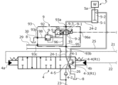
- FIG. 1 is a diagram showing a hydraulic circuit in Example 1.
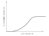
- FIG. 4 is a graph showing the relationship between operating lever stroke and pilot secondary pressure. 4 is a graph showing the relationship between the spool stroke and the opening area when the switching valve is compressed. It is a graph which shows the relationship between an operating lever stroke and the contraction speed of the rod in a cylinder apparatus.
- FIG. 5 is a graph showing the relationship between electrical signals from a controller and preferential flow rates at diverter valves.
- FIG. 4 is a graph showing the relationship between the number of revolutions and the output power in a regeneration mechanism; FIG.
- FIG. 2 is an enlarged view of a main part showing a flow dividing valve device and a switching valve in a neutral position in Embodiment 1;
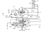
- FIG. 4 is an enlarged view of a main part showing the flow dividing valve device and the switching valve in the operating position in Embodiment 1; It is a figure which shows the hydraulic circuit in Example 2 of this invention. 4 is a graph showing the relationship between the electrical signal from the controller and the opening area of the regeneration valve.
- FIG. 11 is an enlarged view of a main part showing a flow dividing valve device, a regeneration valve, and a switching valve in a neutral position in Embodiment 2;
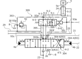
- FIG. 11 is an enlarged view of a main part showing a flow dividing valve device, a regeneration valve, and a switching valve in operating positions in Embodiment 2; It is a figure which shows the hydraulic circuit in Example 3 of this invention.
- FIG. 10 is a perspective view, a plan view, and a side view showing a switching valve and a flow dividing valve device in Example 3;
- FIG. 11 is an enlarged view of a main part showing a flow dividing valve device and a switching valve in a neutral position in Example 3;
- FIG. 11 is an enlarged view of a main part showing a flow dividing valve device and a switching valve in an operating position in Example 3;
- FIG. 5 is a graph showing comparison of rod retraction speed with respect to operating lever stroke during flow splitting;
- 10 is a diagram showing another flow dividing valve that can be applied as a flow dividing valve in Example 3; 10 is a graph showing the relationship between the electrical signal from the controller and the preferential flow rate in still another flow dividing valve that can be applied as the flow dividing valve in Example 3.
- FIG. It is a figure which shows the hydraulic circuit in Example 4 of this invention.
- FIG. 1 A fluid pressure circuit according to Embodiment 1 of the present invention will be described with reference to FIGS. 1 to 9.
- FIG. 1 A fluid pressure circuit according to Embodiment 1 of the present invention will be described with reference to FIGS. 1 to 9.
- a hydraulic circuit as a fluid pressure circuit is a hydraulic circuit for controlling the stroke of a cylinder device in accordance with an operation command of a work machine, construction machine, cargo handling vehicle, automobile, etc.
- the wheel shown in FIG. It is built into the power train of the loader 100.
- the wheel loader 100 is mainly composed of a vehicle body 101, wheels 102 for traveling, a working arm 103, a hydraulic cylinder 104, and a bucket 105 into which gravel or the like is put.
- the vehicle body 101 is provided with an engine 110 such as an engine, a fluid circuit 120 for traveling, a hydraulic cylinder 104, and a working hydraulic circuit 130 for driving the hydraulic cylinder 5 as a cylinder device.
- the hydraulic circuit 130 includes a main hydraulic pump 2 as fluid supply means driven by a drive mechanism 1 such as an engine or an electric motor, a pilot hydraulic pump 3 , a switching valve 4 , a hydraulic cylinder 5 . , a relief valve 6, a relief valve 7, a tank 8, a flow dividing valve device 9, a regeneration motor 10 and a generator 11 as a regeneration mechanism, a remote control valve 12, a pressure sensor 13, a controller 14, and further is composed of oil passages 16 to 31.
- a regenerative motor is exemplified as a regenerative driving source, it is not limited to this.
- the main hydraulic pump 2 is connected to a drive mechanism 1 such as an internal combustion engine, and is driven by power from the drive mechanism 1 to supply pressure oil downstream through an oil passage 23 .
- the pressure oil discharged from the main hydraulic pump 2 flows through the oil passage 23 into the switching valve 4 .
- the switching valve 4 is a 6-port 3-position open center type switching valve. When the spool is in the neutral position, the entire amount of pressure oil discharged from the main hydraulic pump 2 flows through the oil passage 16 to the tank 8. there is
- the pilot hydraulic pump 3 is connected to the drive mechanism 1 and driven by the power from the drive mechanism 1 to supply pressure oil to the downstream side through the oil passage 19.
- part of the pressure oil supplied downstream through the oil passage 19 is supplied through the oil passage 20 to the remote control valve 12 .
- the remote control valve 12 is a variable pressure reducing valve, and when the operating lever 12a operates the rod 5a of the hydraulic cylinder 5 in the extending direction A or the contracting direction B, the operating lever stroke of the operating lever 12a as shown in FIG.
- the extension position (extension amount) or contraction position ( amount of shrinkage) is controlled.
- the amount of operation of the operating lever 12a is substantially equivalent to the stroke of the operating lever 12a, and is called the operating lever stroke.
- the remote control valve 12 outputs a pilot secondary pressure that increases proportionally as the operation lever stroke of the control lever 12a of the remote control valve 12 increases.
- the switching valve 4 is constructed so that the spool strokes in substantially proportion to the pilot secondary pressure of the remote control valve 12, and as shown in FIG. Therefore, as the opening amount increases, the amount of pressure oil supplied to the hydraulic cylinder 5 increases, and as shown in FIG. 5, the operating speed of the rod 5a of the hydraulic cylinder 5 increases. That is, the rod speed can be controlled according to the operation lever stroke of the operation lever 12 a of the remote control valve 12 .
- the switching valve 4 has an oil passage 4-1, a throttle 4-2, an oil passage 4-3, a check valve 4-4, and an oil passage 4-5 on the retracted position side. have.
- the oil passage 4-1 is connected to the oil passages 24-1 and 26 (see FIG. 9).
- a throttle 4-2 is provided in the oil passage 4-1.
- the oil passage 4-3 is branched and connected to the oil passage 4-1 on the hydraulic cylinder 5 side of the throttle 4-2, and is branched and connected to the oil passage 4-5.
- a check valve 4-4 is provided in the oil passage 4-3.
- the oil passage 4-5 is connected to the oil passages 23 and 25 (see FIG. 9).
- the flow rate of return oil discharged from the bottom chamber 5-1 of the hydraulic cylinder 5 and flowing toward the tank 8 is throttled by the throttle 4-2.
- the pressure of the return oil discharged from the bottom chamber 5-1 is easily maintained in the region of the oil passage 4-1 closer to the hydraulic cylinder 5 than the throttle 4-2.
- the return oil discharged from the bottom chamber 5-1 is pressurized by the load W acting in the direction of gravity in addition to the fluid pressure of the oil that has flowed into the rod chamber 5-2. It tends to be higher than the fluid pressure of the oil flowing through passage 4-5.
- the high-pressure oil discharged from the bottom chamber 5-1 of the hydraulic cylinder 5 can be reused to operate the rod 5a of the hydraulic cylinder 5 in the direction of contraction, so that the load on the main hydraulic pump 2 is reduced. can be reduced to achieve energy saving.
- the oil passage 4-3 and the check valve 4-4 are the regeneration passage R1 in the present invention.
- a pilot circuit having a pilot hydraulic pump 3 is provided with a relief valve 7 for controlling the maximum pressure in the circuit. It is discharged to the tank 8 through the passage 27 and the oil passage 28 .
- a flow dividing valve device 9 is provided.
- the flow dividing valve device 9 includes a flow dividing valve 91 which is a 3-port 2-position type normally open electromagnetic proportional throttle valve, a relief valve 92 which controls the maximum pressure in the circuit of the flow dividing valve device 9, and a housing 93 which accommodates them. and are mainly provided.
- the housing 93 is provided with ports 93a-93d, an opening 93e, and oil passages 94-98.
- the port 93a communicates with the oil passage 24-2.
- the port 93b communicates with the oil passage 24-1.
- Port 93 c communicates with oil passage 29 extending from regenerative motor 10 .
- the port 93 d communicates with the oil passage 30 that communicates with the tank 8 .
- An electric signal line connecting the controller 14 and the flow dividing valve 91 is inserted through the opening 93e, which is a through hole.
- the oil passage 94 connects the port 93 a and the flow dividing valve 91 .
- An oil passage 95 connects the flow dividing valve 91 and the port 93b.
- the oil passage 96 connects the flow dividing valve 91 and the port 93c.
- An oil passage 97 connects the oil passage 96 and the relief valve 92 .
- An oil passage 98 connects the relief valve 92 and the port 93d.
- the flow dividing valve 91 is a pressure-compensated electromagnetic proportional control type that can variably divide the flow rate (hereinafter also referred to as priority flow rate) to the oil passage 9-3 side, which will be described later, by an electric signal from the controller 14. It is a flow control valve.
- the flow dividing valve 91 has a flow rate control characteristic as shown in FIG.
- the priority flow rate can be increased or decreased in proportion to the electric signal from 14.
- the flow dividing valve 91 includes an oil passage 9-1, a throttle 9-2, an oil passage 9-3, a throttle 9-4, and an oil passage 9-5.
- a throttle 9-2 is provided in the oil passage 9-1 on the switching valve 4 side of the branched portion of the oil passage 9-3.
- the oil passage 9-3 is branch-connected to the oil passage 9-1 and connected to the oil passage 29 as well.
- a throttle 9-4 is provided in the oil passage 9-3.
- the oil passage 9-1 is connected to the oil passages 24-1 and 24-2 as a function of the position at which the flow dividing valve 91 is switched from the neutral position, that is, the position during regeneration.
- Line 9-5 is connected to line 24-1 and line 24-2 as a function of the neutral position, ie, non-regenerative position.
- a relief valve 92 is installed between the oil passages 97 and 98 in the flow dividing valve device 9 in order to prevent the oil in the oil passage from becoming abnormally high pressure and damage the oil machine in the flow dividing valve device 9.
- the high-pressure oil is discharged to the tank 8 through the oil passages 97, 98 and the oil passage 30.
- the generator 11 is connected to the regenerative motor 10 by a connecting portion 32, and outputs electric power with output characteristics as shown in FIG. Further, when the amount of power generated by the generator 11 reaches the allowable storage amount of the storage device, the electric signal from the controller 14 to the flow dividing valve 91 is cut off and the flow dividing valve 91 returns to the neutral position, whereby the regenerative motor 10 The inflow to the generator 11 is cut off and the power generator 11 is stopped, so that no power is generated.
- a pressure sensor 13 is installed on the pilot signal oil passage 22, and the operation lever 12a of the remote control valve 12 is operated in the contraction direction B, causing the pilot signal oil passage 22 to receive the pilot secondary pressure. is generated, an electrical signal is input from the pressure sensor 13 to the controller 14 .
- the fluid pressure Pr of the return oil on the oil path 4-1 side of the check valve 4-4 of the switching valve 4 is pumped from the main hydraulic pump 2 on the oil path 4-5 side of the check valve 4-4.
- the check valve 4-4 is opened and the return oil is reused as forward oil as indicated by the white arrow in FIG. .
- Part of the return oil that has flowed into the oil passage 4-1 passes through the throttle 4-2 and the oil passage 26 and is discharged to the tank 8.
- the electrical signal is input to the controller 14 and the storage battery has not reached the allowable storage amount
- the electrical signal is output from the arithmetic circuit in the controller 14 to the flow dividing valve 91 .
- the flow dividing valve 91 is switched to the regeneration position.
- the controller 14 controls the flow dividing valve 91 to be switched at the same time when the switching valve 4 is switched.
- the flow dividing valve 91 which has been switched from the neutral position to the regeneration position, allows the return oil that has flowed into the oil passage 9-3 to flow into the oil passage 29 after being throttled by the throttle 9-4.
- the throttle 9-4 restricts the flow rate, in other words, the flow of the return oil is blocked, so that the remaining return oil can be passed through the oil passage 9-1 while being maintained at a suitable primary pressure.
- the hydraulic circuit 130 is configured such that a part of the return oil flows through the oil passage 29 via the flow dividing valve 91 and into the regenerative motor 10 , so that the regenerative motor 10 rotates and electricity is generated by the generator 11 . It's becoming Return oil that has passed through the regenerative motor 10 is discharged to the tank 8 via the oil passage 31 .
- the opening degree of the throttle 9-2 and the opening degree of the throttle 9-4 are such that the fluid pressure of the return oil flowing into the oil passage 24-1 is higher than the fluid pressure of the oil pressure-fed from the main hydraulic pump 2.
- part of the oil returned from the hydraulic cylinder 5 through the throttle 9-4 of the flow dividing valve 91 drives the regenerative motor 10 and then flows into the tank 8. and discharged. Therefore, the pressure of the oil on the primary side of the hydraulic cylinder 5, that is, the oil passing through the oil passages 24-2, 9-1, 24-1 can be stabilized. As a result, it is possible to allow the oil of proper pressure to flow into the oil passage 4-3 and the check valve 4-4 side. Therefore, an energy-saving circuit can be obtained.
- the switching valve 4 is arranged near the flow dividing valve 91, in other words, only through the oil passage 24-1. Therefore, by synchronizing the timing of switching the flow dividing valve 91 from the non-regenerative position to the regenerating position with the timing of switching the switching valve 4 from the neutral position to the retracted position, the flow dividing valve 91 is shifted from the oil passage 24-2.
- the return oil is allowed to flow smoothly into the oil passages 9-1, 24-1 and 4-1 of the switching valve 4, and from the oil passage 24-2 to the oil passages 9-3 and 29 of the diverting valve 91. can smoothly return and allow oil to flow in. In this way, when the return oil flowing through the oil passage 24-2 is branched, it is easy to control the timing of switching the flow dividing valve 91 and the timing of switching the switching valve 4.
- the regeneration passage R1 in this embodiment is provided in the switching valve 4, and part of the return oil that has flowed into the oil passage 4-1 directly flows into the oil passage 4-3.
- the regeneration passage is provided separately from the switching valve (for example, the case described in the second embodiment described later)
- the influence of the flow path resistance, etc. acting on the return oil is reduced. be able to. Therefore, the return oil used for regeneration is efficiently supplied to the hydraulic cylinder 5 side.
- synchronization control is easier than in the case of individually synchronizing the switching valve, the flow dividing valve, and the regeneration passage.
- the regeneration passage R1 of the present embodiment is provided on the retracted position side of the switching valve 4, by utilizing the gravity acting on the hydraulic cylinder 5, the fluid on the primary side on the hydraulic cylinder 5 side can be more reliably discharged. pressure can be ensured.
- the flow dividing valve 91 has been described as having the throttles 9-2 and 9-4 provided in the oil passages 9-1 and 9-3, the oil passage 9-1 is not limited to this configuration. It does not have to be provided. Even with such a configuration, the preferential flow rate passing through the oil passage 9-3 and the throttle 9-4 can be ensured by the throttle 4-2 and the check valve 4-4 in the switching valve 4.
- FIG. 1 the preferential flow rate passing through the oil passage 9-3 and the throttle 9-4 can be ensured by the throttle 4-2 and the check valve 4-4 in the switching valve 4.
- the switching valve 204 is not provided with a regeneration passage, and the regeneration valve 40 is provided between the switching valve 204 and the flow dividing valve device 9. It differs from the first embodiment in that it has the same configuration as the first embodiment in other respects.
- the regeneration valve 40 is a 4-port 2-position type electromagnetic proportional valve, and is a flow rate control valve that can variably control the flow rate by an electric signal from the controller 14.
- the regeneration valve 40 has an oil path 40-1, an oil path 40-2, a check valve 40-3, and an oil path 40-4 on the regeneration position side where the return oil can be supplied to the oil path 25-2. It has The oil passage 40-1 is connected to the oil passages 24-1a and 24-1b.
- the oil passage 40-2 is branched and connected to the oil passages 40-1 and 40-4.
- a check valve 40-3 is provided in the oil passage 40-2.
- the oil passage 40-4 is connected to the oil passages 25-1 and 25-2.
- the regeneration valve 40 is configured such that the spool strokes approximately in proportion to the electric signal from the controller 14, and as shown in FIG. ing.
- the regeneration valve 40 In the neutral position of the regeneration valve 40, the regeneration valve 40 connects the oil passages 24-1a and 24-1b, and connects the oil passages 25-1 and 25-2. On the other hand, the regeneration path is omitted.
- the regeneration valve 40 receives an electric signal to the controller 14 in the same manner as the flow dividing valve 91, or an electric signal according to the state of charge of the electric storage device (not shown). .
- the pressure Pr of the return oil on the oil passage 40-1 side of the check valve 40-3 of the regeneration valve 40 and the fluid pressure Pf of the outgoing oil on the oil passage 40-4 side of the check valve 40-3 Since the check valve 40-3 is opened according to the differential pressure ⁇ P, the return oil can be reused as the outgoing oil, as indicated by the white arrow in FIG.
- the oil passage 40-2 and the check valve 40-3 are the regeneration passage R2 in this embodiment.
- the regeneration passage may be provided in addition to the switching valve.
- the hydraulic circuit 330 in the third embodiment includes a switching valve 304 (see FIG. 14), which is a 3-position 7-port open center switching valve, and a 4-port 2-position normal switching valve. It has a flow dividing valve device 309 (see FIG. 14) which is an open type electromagnetic proportional throttle valve.
- the housing of switching valve 304 and the housing 393 of flow dividing valve device 309 are abutted and fixed by four bolts (see FIG. 15).
- the housing of the switching valve 4 and the housing 93 of the flow dividing valve device 9 may be abutted and fixed. The same applies to the second embodiment.
- the switching valve 304 includes an oil passage 4-1, a throttle 4-2, an oil passage 304-3, a check valve 304-4, an oil passage 4- 5 and an oil passage 304-6.
- the oil passage 304-3 is branched and connected to the hydraulic cylinder 5 side of the throttle 4-2 in the oil passage 4-1, and is branched and connected to the oil passage 304-6.
- a check valve 304-4 is provided in the oil passage 304-6.
- the oil passage 304-6 is branch-connected to the oil passage 4-5 and connected to the oil passage 399 in the flow dividing valve device 309 (see FIG. 17).
- the flow dividing valve device 309 mainly includes a flow dividing valve 391, a relief valve 92, and a housing 393 that accommodates them.
- the housing 393 is provided with ports 93a, 93c, 93d, 393b, 393f, an opening 93e, and oil passages 94, 96-98, 395, 399.
- the port 393b is directly connected to the port of the switching valve 304 to which the oil passage 4-1 is switched.
- the port 393f is directly connected to the port of the switching valve 304 to which the oil passage 304-6 is switched.
- the oil passage 395 connects the flow dividing valve 391 and the port 393b.
- An oil passage 399 connects the flow dividing valve 391 and the port 393f.
- the flow dividing valve 391 includes an oil passage 9-1, an oil passage 9-2, an oil passage 9-3, an oil passage 9-4, an oil passage 9-5, and an oil passage 9-6.
- a throttle 9-2 is provided in the oil passage 9-1 on the switching valve 4 side of the branched portion of the oil passage 9-3.
- the oil passage 9-3 is branch-connected to the oil passage 9-1 and connected to the oil passage 29 as well.
- a throttle 9-4 is provided in the oil passage 9-3.
- the oil passage 9-6 is branched from the oil passage 9-1 and connected to the oil passage 399 (see FIG. 17). Further, the oil passage 9-6 is a passage having a smaller fluid resistance than the oil passage 9-3, and is different from the oil passages 9-1 and 9-3 in that no throttle is provided.
- the oil passage 9-6, 399 is a passage with low fluid resistance in this embodiment.
- part of the return oil that has flowed into the flow dividing valve 391, passed through the throttle 9-2, and flowed into the oil passage 4-1 of the switching valve 304 is transferred through the oil passage 304-3 to the oil passage 304-6.
- this flow rate is small, so it is not indicated by a white arrow in FIG. 17.
- the check valve 304-4 When the check valve 304-4 is opened, it flows into the oil passage 4-5, and the rod in the hydraulic cylinder 5 supplied to chamber 5-2.
- the oil passage 304-3, the check valve 304-4 and the oil passage 304-6 are the regeneration passage R3 in this embodiment.
- the hydraulic circuit 330 in this embodiment indicated by the solid line in the graph of FIG. 18 increases the operating speed of the hydraulic cylinder 5 compared to the hydraulic circuits 130 and 230 in the first and second embodiments indicated by the dotted line. be able to. In other words, it is possible to prevent the operating speed of the hydraulic cylinder 5 from lowering compared to when the flow dividing device is in the non-dividing position.
- pressure oil is regenerated through the oil passage 9-6 having a small fluid resistance. Regeneration efficiency is enhanced because the return oil discharged from the engine can be preferentially used for regeneration.
- the flow dividing valve device 309 is integrally attached to the switching valve 304, the flow path resistance acting when the return fluid passes through the flow dividing valve device 309 and the switching valve 304 can be reduced. Further, when the switching valve 304 and the flow dividing valve device 309 are assembled to the hydraulic circuit 330, the oil passages connected to the switching valve 304 and the flow dividing valve device 309 are only the oil passages 23, 24-2, 25, and 29. Good workability.
- oil passage 9-6 which is a passage with low fluid resistance
- another passage branched from the passage communicating with the flow dividing valve is a passage with low fluid resistance.
- the fluid pressure circuit can be configured simply compared to the configuration.
- the present invention is not limited to this, and the number of bolts may be changed as appropriate. may be fixed by a fixing means. Also, the switching valve and the flow dividing valve device may be integrally configured.
- flow dividing valve 391 in this embodiment is an electromagnetic proportional control type valve, it is not limited to this.
- FIG. valve 315 This also applies to the first and second embodiments.
- the flow dividing valve 391 in the present embodiment is a pressure-compensated electromagnetic proportional control type flow control valve, but is not limited to this.
- the flow dividing valve 391 in the present embodiment is a pressure-compensated electromagnetic proportional control type flow control valve, but is not limited to this.
- as shown in FIG. may be constant. This also applies to the first and second embodiments.
- the switching valve 304 in this embodiment has been described as having the oil passage 304-3, the present invention is not limited to this, and the oil passage 304-3 may be omitted.
- the hydraulic circuit 430 in the fourth embodiment differs from the second embodiment in that the regeneration valve 40 is provided between the hydraulic cylinder 5 and the flow dividing valve device 9. have almost the same configuration.
- the regeneration valve 40 is connected to the oil passages 24-2a and 24-2b between the hydraulic cylinder 5 and the flow dividing valve device 9, and is connected to the oil passage 25-1 between the switching valve 204 and the hydraulic cylinder 5. and the oil passage 25-2.
- the oil passage 40-1 in the regeneration valve 40 is arranged closer to the hydraulic cylinder 5 than the oil passages 9-1 and 9-3 in the flow dividing valve 91, while the restriction is omitted. A portion of the return oil can be led preferentially to the oil passage 40-2.
- the oil passage 40-1 is a passage with low fluid resistance in this embodiment. Therefore, like the third embodiment, it is possible to prevent the operating speed of the hydraulic cylinder 5 from decreasing. Thus, the passage with low fluid resistance may be provided outside the flow dividing valve.
- the valve of the present invention has been described as being a flow dividing valve, but it is not limited to this, and may be a valve that does not have a flow dividing function as long as it has a throttle.
- another passage that is branched from the passage that communicates with the valve may be connectable to the regeneration passage.
- a throttle may or may not be provided in the middle of another passage connectable to the regeneration passage.
- the flow dividing valve is configured to divide the flow into one regeneration passage side and one regeneration mechanism side. There may be a configuration in which the flow is split to each.
- the fluid supply source for pressurizing the fluid in the tank is not limited to the hydraulic pump, and can be variously changed according to the fluid used in the fluid pressure circuit, such as an air cylinder or an accumulator.
- the structure is described in which the regenerative motor is connected to the flow dividing valve through the oil passage. It may be provided, another cylinder device may be provided, and the configuration connected to the flow dividing valve may be changed as appropriate.
Landscapes
- Engineering & Computer Science (AREA)
- General Engineering & Computer Science (AREA)
- Physics & Mathematics (AREA)
- Fluid Mechanics (AREA)
- Mechanical Engineering (AREA)
- Chemical & Material Sciences (AREA)
- Analytical Chemistry (AREA)
- Mining & Mineral Resources (AREA)
- Civil Engineering (AREA)
- Structural Engineering (AREA)
- Fluid-Pressure Circuits (AREA)
Priority Applications (4)
| Application Number | Priority Date | Filing Date | Title |
|---|---|---|---|
| CN202380022509.3A CN118715379A (zh) | 2022-02-28 | 2023-02-17 | 流体压回路 |
| US18/841,655 US20250180043A1 (en) | 2022-02-28 | 2023-02-17 | Fluid pressure circuit |
| JP2024503108A JPWO2023162883A1 (https=) | 2022-02-28 | 2023-02-17 | |
| EP23759884.2A EP4488527A4 (en) | 2022-02-28 | 2023-02-17 | FLUID PRESSURE CIRCUIT |
Applications Claiming Priority (2)
| Application Number | Priority Date | Filing Date | Title |
|---|---|---|---|
| JP2022029996 | 2022-02-28 | ||
| JP2022-029996 | 2022-02-28 |
Publications (1)
| Publication Number | Publication Date |
|---|---|
| WO2023162883A1 true WO2023162883A1 (ja) | 2023-08-31 |
Family
ID=87765748
Family Applications (1)
| Application Number | Title | Priority Date | Filing Date |
|---|---|---|---|
| PCT/JP2023/005748 Ceased WO2023162883A1 (ja) | 2022-02-28 | 2023-02-17 | 流体圧回路 |
Country Status (5)
| Country | Link |
|---|---|
| US (1) | US20250180043A1 (https=) |
| EP (1) | EP4488527A4 (https=) |
| JP (1) | JPWO2023162883A1 (https=) |
| CN (1) | CN118715379A (https=) |
| WO (1) | WO2023162883A1 (https=) |
Citations (3)
| Publication number | Priority date | Publication date | Assignee | Title |
|---|---|---|---|---|
| JP2016014398A (ja) * | 2014-06-30 | 2016-01-28 | 日立建機株式会社 | 建設機械の油圧システム |
| WO2018147261A1 (ja) | 2017-02-10 | 2018-08-16 | イーグル工業株式会社 | 流体圧回路 |
| US20200123737A1 (en) * | 2017-04-10 | 2020-04-23 | Doosan Infracore Co., Ltd. | Hydraulic system of construction machinery |
Family Cites Families (15)
| Publication number | Priority date | Publication date | Assignee | Title |
|---|---|---|---|---|
| JPS622805U (https=) * | 1985-06-20 | 1987-01-09 | ||
| DE69021706T2 (de) * | 1989-06-26 | 1996-03-07 | Kabushiki Kaisha Komatsu Seisakusho, Tokio/Tokyo | Hydraulische schaltung zum betrieb einer maschine. |
| US5251705A (en) * | 1992-03-19 | 1993-10-12 | Deere & Company | Electrical trigger for quick drop valve |
| KR100305742B1 (ko) * | 1996-05-25 | 2001-11-30 | 토니헬샴 | 중장비의재생장치 |
| US5701933A (en) * | 1996-06-27 | 1997-12-30 | Caterpillar Inc. | Hydraulic control system having a bypass valve |
| CN100354561C (zh) * | 2001-12-11 | 2007-12-12 | 萱场工业株式会社 | 电磁比例流量控制阀 |
| JP5323753B2 (ja) * | 2010-03-26 | 2013-10-23 | カヤバ工業株式会社 | 建設機械の制御装置 |
| US9279236B2 (en) * | 2012-06-04 | 2016-03-08 | Caterpillar Inc. | Electro-hydraulic system for recovering and reusing potential energy |
| CN104919116B (zh) * | 2013-01-18 | 2017-12-19 | 沃尔沃建造设备有限公司 | 用于工程机械的控流装置和控流方法 |
| JP6155159B2 (ja) * | 2013-10-11 | 2017-06-28 | Kyb株式会社 | ハイブリッド建設機械の制御システム |
| JP6324825B2 (ja) * | 2014-07-03 | 2018-05-16 | ナブテスコ株式会社 | 建設機械用油圧回路 |
| JP2016098588A (ja) * | 2014-11-25 | 2016-05-30 | Kyb株式会社 | ハイブリッド建設機械の制御システム |
| JP2017015118A (ja) * | 2015-06-29 | 2017-01-19 | Kyb株式会社 | 建設機械の制御システム |
| US20220252084A1 (en) * | 2019-07-17 | 2022-08-11 | Hyundai Doosan Infracore Co., Ltd. | Construction machine and control method therefor |
| JP7379226B2 (ja) * | 2020-03-17 | 2023-11-14 | 株式会社小松製作所 | 油圧システム |
-
2023
- 2023-02-17 JP JP2024503108A patent/JPWO2023162883A1/ja active Pending
- 2023-02-17 EP EP23759884.2A patent/EP4488527A4/en active Pending
- 2023-02-17 US US18/841,655 patent/US20250180043A1/en active Pending
- 2023-02-17 CN CN202380022509.3A patent/CN118715379A/zh active Pending
- 2023-02-17 WO PCT/JP2023/005748 patent/WO2023162883A1/ja not_active Ceased
Patent Citations (3)
| Publication number | Priority date | Publication date | Assignee | Title |
|---|---|---|---|---|
| JP2016014398A (ja) * | 2014-06-30 | 2016-01-28 | 日立建機株式会社 | 建設機械の油圧システム |
| WO2018147261A1 (ja) | 2017-02-10 | 2018-08-16 | イーグル工業株式会社 | 流体圧回路 |
| US20200123737A1 (en) * | 2017-04-10 | 2020-04-23 | Doosan Infracore Co., Ltd. | Hydraulic system of construction machinery |
Non-Patent Citations (1)
| Title |
|---|
| See also references of EP4488527A4 |
Also Published As
| Publication number | Publication date |
|---|---|
| EP4488527A4 (en) | 2026-02-25 |
| CN118715379A (zh) | 2024-09-27 |
| EP4488527A1 (en) | 2025-01-08 |
| JPWO2023162883A1 (https=) | 2023-08-31 |
| US20250180043A1 (en) | 2025-06-05 |
Similar Documents
| Publication | Publication Date | Title |
|---|---|---|
| JP5564215B2 (ja) | 建設機械用油圧システム | |
| US9938691B2 (en) | Hydraulic system for work machine | |
| US11371535B2 (en) | Fluid pressure circuit | |
| US6330797B1 (en) | Hydraulic circuit for turning excavator | |
| US20080314038A1 (en) | Swing Drive Device and Work Machine | |
| US20090288408A1 (en) | Hydraulic circuit, energy recovery device, and hydraulic circuit for work machine | |
| US10604916B2 (en) | Shovel | |
| JP6005185B2 (ja) | 建設機械の油圧駆動装置 | |
| JP2010270527A (ja) | 作業機 | |
| CN105008729A (zh) | 工程机械的能量再生系统 | |
| JP4380643B2 (ja) | 作業機械の油圧制御装置 | |
| KR102345858B1 (ko) | 건설 기계용 유압 회로 | |
| JP6974366B2 (ja) | 流体圧回路 | |
| JP2008275100A (ja) | 建設車両 | |
| JP4222995B2 (ja) | 建設機械の油圧シリンダ駆動装置 | |
| JP2017125537A (ja) | ハイブリッド作業機の制御システム | |
| WO2023162883A1 (ja) | 流体圧回路 | |
| KR102349181B1 (ko) | 압력 손실을 개선한 지게차용 스티어링의 유압시스템 | |
| JP5269699B2 (ja) | 油圧式作業車両 | |
| WO2023162884A1 (ja) | 流体圧回路 | |
| JP2006336849A (ja) | 旋回用駆動装置 | |
| JP2006336433A (ja) | 作業機械の流体圧回路 | |
| JP2006336304A (ja) | 作業機械 | |
| KR20240087638A (ko) | 쇼벨 | |
| CN119790238A (zh) | 流体压回路 |
Legal Events
| Date | Code | Title | Description |
|---|---|---|---|
| 121 | Ep: the epo has been informed by wipo that ep was designated in this application |
Ref document number: 23759884 Country of ref document: EP Kind code of ref document: A1 |
|
| ENP | Entry into the national phase |
Ref document number: 2024503108 Country of ref document: JP Kind code of ref document: A |
|
| WWE | Wipo information: entry into national phase |
Ref document number: 202380022509.3 Country of ref document: CN |
|
| WWE | Wipo information: entry into national phase |
Ref document number: 202427062819 Country of ref document: IN |
|
| WWE | Wipo information: entry into national phase |
Ref document number: 18841655 Country of ref document: US |
|
| WWE | Wipo information: entry into national phase |
Ref document number: 2023759884 Country of ref document: EP |
|
| NENP | Non-entry into the national phase |
Ref country code: DE |
|
| ENP | Entry into the national phase |
Ref document number: 2023759884 Country of ref document: EP Effective date: 20240930 |
|
| WWP | Wipo information: published in national office |
Ref document number: 18841655 Country of ref document: US |