WO2023162083A1 - 潤滑状態判定装置 - Google Patents
潤滑状態判定装置 Download PDFInfo
- Publication number
- WO2023162083A1 WO2023162083A1 PCT/JP2022/007576 JP2022007576W WO2023162083A1 WO 2023162083 A1 WO2023162083 A1 WO 2023162083A1 JP 2022007576 W JP2022007576 W JP 2022007576W WO 2023162083 A1 WO2023162083 A1 WO 2023162083A1
- Authority
- WO
- WIPO (PCT)
- Prior art keywords
- signal
- rotating shaft
- bearing
- determination device
- amplitude
- Prior art date
Links
- 238000005461 lubrication Methods 0.000 title claims abstract description 49
- 239000010687 lubricating oil Substances 0.000 claims abstract description 64
- 230000005540 biological transmission Effects 0.000 claims abstract description 3
- 239000003921 oil Substances 0.000 claims description 40
- 238000012545 processing Methods 0.000 description 66
- 230000001050 lubricating effect Effects 0.000 description 25
- 230000002159 abnormal effect Effects 0.000 description 23
- 238000010586 diagram Methods 0.000 description 23
- 238000001228 spectrum Methods 0.000 description 17
- 230000002093 peripheral effect Effects 0.000 description 15
- 238000000034 method Methods 0.000 description 8
- 239000000919 ceramic Substances 0.000 description 7
- 230000007423 decrease Effects 0.000 description 7
- 238000005259 measurement Methods 0.000 description 5
- 230000000694 effects Effects 0.000 description 3
- 238000000926 separation method Methods 0.000 description 3
- XEEYBQQBJWHFJM-UHFFFAOYSA-N Iron Chemical compound [Fe] XEEYBQQBJWHFJM-UHFFFAOYSA-N 0.000 description 2
- 230000002547 anomalous effect Effects 0.000 description 2
- 239000000284 extract Substances 0.000 description 2
- 238000005096 rolling process Methods 0.000 description 2
- 230000001133 acceleration Effects 0.000 description 1
- 238000013459 approach Methods 0.000 description 1
- 230000002238 attenuated effect Effects 0.000 description 1
- 238000012937 correction Methods 0.000 description 1
- 238000013461 design Methods 0.000 description 1
- 230000008034 disappearance Effects 0.000 description 1
- 238000000605 extraction Methods 0.000 description 1
- 238000005187 foaming Methods 0.000 description 1
- 230000006870 function Effects 0.000 description 1
- 229910052742 iron Inorganic materials 0.000 description 1
- 239000000463 material Substances 0.000 description 1
- 239000007769 metal material Substances 0.000 description 1
- 239000003507 refrigerant Substances 0.000 description 1
- 238000005057 refrigeration Methods 0.000 description 1
- 238000011160 research Methods 0.000 description 1
- 230000035945 sensitivity Effects 0.000 description 1
- 238000004381 surface treatment Methods 0.000 description 1
Images


Classifications
-
- G—PHYSICS
- G01—MEASURING; TESTING
- G01N—INVESTIGATING OR ANALYSING MATERIALS BY DETERMINING THEIR CHEMICAL OR PHYSICAL PROPERTIES
- G01N29/00—Investigating or analysing materials by the use of ultrasonic, sonic or infrasonic waves; Visualisation of the interior of objects by transmitting ultrasonic or sonic waves through the object
- G01N29/02—Analysing fluids
-
- G—PHYSICS
- G01—MEASURING; TESTING
- G01N—INVESTIGATING OR ANALYSING MATERIALS BY DETERMINING THEIR CHEMICAL OR PHYSICAL PROPERTIES
- G01N29/00—Investigating or analysing materials by the use of ultrasonic, sonic or infrasonic waves; Visualisation of the interior of objects by transmitting ultrasonic or sonic waves through the object
- G01N29/14—Investigating or analysing materials by the use of ultrasonic, sonic or infrasonic waves; Visualisation of the interior of objects by transmitting ultrasonic or sonic waves through the object using acoustic emission techniques
Definitions
- the present disclosure relates to a lubrication state determination device that determines the state of lubricating oil existing between a rotating shaft and a bearing.
- Patent Literature 1 A device is known that determines the state of lubricating oil present in a portion where members made of metal materials slide. See, for example, Patent Literature 1 and Non-Patent Literature 1.
- the device of Patent Document 1 determines the state of lubricating oil existing between the piston and cylinder of the engine.
- the device of Patent Document 1 has a piezoelectric element that detects an acoustic emission wave that is generated when the piston and cylinder come into contact without lubricating oil.
- the device of Non-Patent Document 1 uses ultrasonic waves to determine the state of the lubricating oil present between the rotating shaft and the sintered bearing.
- the device of Non-Patent Document 1 measures the interference wave between the reflected wave of the ultrasonic wave reflected by the outer peripheral surface of the sintered bearing and the reflected wave of the ultrasonic wave reflected by the outer peripheral surface of the rotating shaft. Measuring oil film thickness.
- the present disclosure aims to improve the accuracy of determining the state of lubricating oil existing between the rotating shaft and the bearing.
- a lubrication state determination device is present between a rotating shaft, a bearing that supports the rotating shaft, and a first surface of the rotating shaft and a second surface of the bearing that face each other.
- a lubricating state determination device for determining the state of the lubricating oil in a device having lubricating oil comprising a transmitting unit that transmits an acoustic output wave that is an ultrasonic wave or a sound wave, and a reflected wave of the received acoustic output wave a receiver that receives a first signal that is an amplitude signal corresponding to a certain acoustic input wave and a second signal that is a signal in the frequency band of an acoustic emission wave caused by contact between the rotating shaft and the bearing; and a control unit that determines the state of the lubricating oil based on the first signal and the second signal.
- FIG. 1 is a configuration diagram schematically showing the configuration of a lubricating state determining device according to Embodiment 1 and the configuration of a device to be determined by the lubricating state determining device;
- 1 is a block diagram showing the configuration of a lubricating state determination device according to Embodiment 1;
- FIG. 4 is a block diagram showing another example of the configuration of the lubricating state determination device according to Embodiment 1;
- FIG. FIG. 3A is a diagram schematically showing an example of a hardware configuration of a control device for the lubricating state determination device according to Embodiment 1;
- FIG. 4B is a diagram schematically showing another example of the hardware configuration of the control device for the lubricating state determination device according to Embodiment 1;
- FIG. FIG. 3 is an explanatory diagram for explaining the principle of measuring oil film thickness by reflected waves of ultrasonic waves transmitted from the sensors shown in FIGS. 1 and 2;
- FIG. 2 is a diagram showing the relationship between the distance between the rotating shaft and the bearing shown in FIG. 1, the intensity of ultrasonic waves, and the film thickness of lubricating oil.
- FIG. 2 is a diagram showing a normal reference waveform and an abnormal first waveform of an echo signal output from the sensor shown in FIG. 1;
- FIG. 2 is a diagram showing a normal reference waveform and an abnormal second waveform of an echo signal output from the sensor shown in FIG. 1;
- FIG. 3 is a diagram showing a normal reference waveform and an abnormal third waveform of an echo signal output from the sensor shown in FIG. 1;
- FIG. 2 is a diagram showing the frequency spectrum of an AE signal output from the sensor shown in FIG. 1;
- FIG. 4 is a flowchart showing an example of processing contents of a control device of the lubricating state determination device according to Embodiment 1;
- FIG. 7 is a configuration diagram schematically showing the configuration of a lubricating state determining device and the configuration of a device to be determined by the lubricating state determining device according to Embodiment 2;
- FIG. 11 is a block diagram showing the configuration of a lubrication state determination device according to Embodiment 3;
- FIG. 11 is a flow chart showing an example of processing contents of a control device of a lubricating state determination device according to Embodiment 3;
- FIG. (A) is a diagram showing a frequency spectrum when an echo signal output from a sensor of the lubricating state determination device according to Embodiment 3 is subjected to fast Fourier transform processing.
- (B) is a graph showing the tracking result of the peak value of the frequency spectrum shown in FIG. 15(A).
- a lubrication state determination device according to an embodiment of the present disclosure will be described below with reference to the drawings.
- the following embodiments are merely examples, and the embodiments can be combined as appropriate and each embodiment can be modified as appropriate.
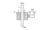
- FIG. 1 is a configuration diagram schematically showing the configuration of a lubrication state determination device 100 according to Embodiment 1 and the configuration of a device 5 to be determined by the lubrication state determination device 100.
- the lubricating state determination device 100 determines the state of the lubricating oil 3 existing between the rotating shaft 1 and the bearing 2 in the device 5 having the rotating shaft 1, the bearing 2, and the lubricating oil 3 (hereinafter also referred to as "lubricating state” ) is determined.
- the lubricating state determining device 100 determines, for example, the state of the lubricating oil 3 when the rotary shaft 1 is rotating around the axis Ax.
- the lubricating state determination device 100 can also determine the state of the lubricating oil 3 when the rotary shaft 1 is not rotating.
- the device 5 shown in FIG. 1 is, for example, a rotating machine such as a compressor provided in a refrigeration cycle device (eg, an air conditioner).
- the bearing 2 is, for example, a cylindrical plain bearing (that is, a journal bearing).
- the lubricating oil 3 exists between the outer peripheral surface 1a of the rotating shaft 1 as a first surface and the inner peripheral surface 2b of the bearing 2 as a second surface.
- An outer peripheral surface 1 a of the rotating shaft 1 is a boundary surface between the rotating shaft 1 and the lubricating oil 3
- an inner peripheral surface 2 b of the bearing 2 is a boundary surface between the bearing 2 and the lubricating oil 3 .
- the bearing 2 is not limited to a slide bearing, and may be a rolling bearing, and the lubrication state determining device 100 may determine the state of the lubricating oil 3 between the rotating shaft 1 and the rolling bearing.
- FIG. 2 is a block diagram showing the configuration of the lubrication state determination device 100 according to Embodiment 1. As shown in FIG. As shown in FIGS. 1 and 2, the lubrication state determination device 100 has a sensor 10 and a control device 20 as a control section.
- the sensor 10 is, for example, an ultrasonic sensor.
- the sensor 10 is provided on the bearing 2 .
- part of the sensor 10 is fixed inside the bearing 2 .
- the sensor 10 may be provided on the rotary shaft 201 as shown in FIG. 12 described later.
- the sensor 10 has a transmitter 11 and a receiver 12 .
- Each of the transmitter 11 and receiver 12 has a piezoelectric element (for example, a ceramic vibrator).
- the transmission unit 11 transmits an ultrasonic wave generated by a driving signal (voltage signal) transmitted from a pulsar receiver 31 to be described later toward the lubricating oil 3 .
- the receiving unit 12 receives interference waves of the reflected ultrasonic waves transmitted from the transmitting unit 11 .
- the receiving unit 12 outputs a signal having an amplitude corresponding to the interference wave to the pulser receiver 31 . Note that the interference wave will be described later with reference to FIG.
- FIG. 3 is a block diagram showing another example of the configuration of the lubrication state determination device 100 according to Embodiment 1.
- the sensor 10 may have a transmitter/receiver 13 in which the transmitter 11 and receiver 12 shown in FIG. 2 are integrated.
- the transmitting/receiving unit 13 transmits an ultrasonic wave generated by the driving signal transmitted from the pulsar receiver 31 toward the lubricating oil 3 and receives an interference wave of the reflected wave of the ultrasonic wave.
- the control device 20 has a signal processing section 30 and a rotating shaft control section 40 .
- the signal processing section 30 has a pulser receiver 31 and a signal waveform processing section 32 .
- the pulsar receiver 31 transmits a drive signal for driving the transmitter 11 and receives a signal output from the receiver 12 .
- the signal waveform processing section 32 determines the state of the lubricating oil 3 (see FIG. 1) based on the signal output from the pulser receiver 31 .
- the rotating shaft control unit 40 controls the rotating operation of the rotating shaft 1 (see FIG. 1) in the device 5 based on the determination result of the signal waveform processing unit 32 . Specifically, when the signal waveform processing unit 32 determines that the lubrication state between the rotating shaft 1 and the bearing 2 is normal, the rotating shaft control unit 40 allows the rotating shaft 1 to continue rotating. On the other hand, when the signal waveform processing unit 32 determines that the lubrication state between the rotating shaft 1 and the bearing 2 is poor, the rotating shaft control unit 40 reduces the rotation speed of the rotating shaft 1 or reduces the rotation speed of the rotating shaft 1 stop rotating. Note that the rotating shaft control unit 40 may adjust the rotation load on the rotating shaft 1 when it is determined that the lubricating state is poor.
- FIG. 4A is a diagram schematically showing an example of the hardware configuration of the control device 20 of the lubrication condition determination device 100.
- the control device 20 of the lubricating state determination device 100 includes, for example, a memory 20a as a storage device that stores a program as software, and information that implements the program stored in the memory 20a. It can be realized by using a processor 20b as a processing unit (for example, by a computer). Note that part of the control device 20 may be implemented by the memory 20a shown in FIG. 4A and the processor 20b that executes the program. Also, the control device 20 may be realized by an electric circuit.
- FIG. 4(B) is a diagram schematically showing another example of the hardware configuration of the control device 20 of the lubrication condition determination device 100.
- the control device 20 may be implemented using a processing circuit 20c as dedicated hardware such as a single circuit or multiple circuits. In this case, the functions of the control device 20 are realized by the processing circuit 20c.
- FIG. 5 is an explanatory diagram for explaining the principle of measuring the oil film thickness L by the reflected wave of the ultrasonic wave U1 transmitted from the sensor 10 shown in FIGS.
- the ultrasonic wave U1 transmitted from the sensor 10 passes through the inside of the bearing 2 and is internally reflected by the inner peripheral surface 2b of the bearing 2. Also, the ultrasonic wave U1 passes through the bearing 2 and the lubricating oil 3 and is reflected by the outer peripheral surface 1a of the rotating shaft 1 .
- the reflected wave of the ultrasonic wave U1 internally reflected by the inner peripheral surface 2b of the bearing 2 is R1
- the reflected wave of the ultrasonic wave U1 reflected by the outer peripheral surface 1a of the rotating shaft 1 is R2.
- the receiving unit 12 shown in FIG. 2 receives the interference waves of the reflected waves R1 and R2.
- the senor 10 may transmit, for example, a sound wave with a frequency slightly lower than 20 kHz instead of the ultrasonic wave U1.
- the transmitter 11 shown in FIG. 2 transmits an acoustic output wave that is an ultrasonic wave or a sound wave
- the receiver 12 receives an acoustic input wave that is a reflected wave of the acoustic output wave.
- the wavelength ⁇ is as follows. is represented by the formula (1).
- ⁇ c/f (1)
- the wavelength ⁇ is 2.8 mm.
- the "driving frequency” is the frequency of the voltage signal applied to the ceramic vibrator of the transmitter 11 shown in FIG. 2 (or the transmitter/receiver 13 shown in FIG. 3).
- the inner peripheral surface 2b of the bearing 2 which is the boundary surface between the bearing 2 and the lubricating oil 3 in FIG.
- the distance up to 10 (hereinafter also referred to as "separation distance") is a distance equal to or greater than one wavelength of the ultrasonic wave U1. Specifically, the separation distance is 2.8 mm or more. Note that the separation distance may be appropriately changed according to the load of the device 5, the shape of the bearing 2, and the like.
- the pulsar receiver 31 (see FIG. 2) generates a first signal (hereinafter also referred to as an “echo signal”), which is a signal having an amplitude corresponding to the interference waves of the reflected waves R1 and R2 output from the receiving section 12, as follows: Output to the signal waveform processing unit 32 .
- the signal waveform processing unit 32 (see FIG. 2) detects the magnitude (intensity) of the interference wave based on the echo signal, and measures the oil film thickness L based on the magnitude of the interference wave.
- FIG. 6 is a graph showing the relationship between the oil film thickness L and the magnitude of the interference wave.
- the vertical axis indicates the amplitude peak, which is the peak value in the waveform component of the interference wave
- the horizontal axis indicates the oil film thickness L (unit: ⁇ m).
- the dashed line graph shows the ideal relationship between the oil film thickness L and the amplitude peak of the echo signal.
- each of the multiple plots shown in FIG. 6 indicates actual measured values.
- the amplitude peak of the echo signal increases in proportion to the oil film thickness L.
- the signal waveform processing section 32 can determine the state of the lubricating oil 3 existing between the rotating shaft 1 and the bearing 2 based on the amplitude peak of the echo signal.
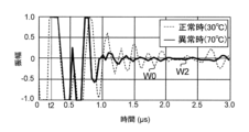
- FIG. 7 shows a reference waveform W0 showing the normal waveform of the echo signal output from the sensor 10 shown in FIG. ) is a graph showing W1.
- the reference waveform W0 is represented by a broken line graph
- the first abnormal waveform W1 is represented by a solid line graph.
- the horizontal axis indicates time (unit: ⁇ s)
- the vertical axis indicates the amplitude of the echo signal.
- a reference waveform W0 is a waveform of an echo signal detected when the oil film thickness L between the rotary shaft 1 and the bearing 2 is normal and the temperature of the bearing 2 (or the lubricating oil 3) is 30°C. be.
- the oil film thickness L is normal means, for example, that the oil film thickness L is thicker than a predetermined set value.
- the first abnormal waveform W1 is the waveform of the echo signal detected when the oil film thickness L is not good and the temperature of the lubricating oil 3 is 30°C.
- the first abnormal waveform W1 is the echo signal before seizure occurs in at least one of the rotating shaft 1 and the bearing 2 due to the approach of the bearing 2 to the rotating shaft 1 due to the oil film thickness L being thinner than the set value. shows the waveform. As shown in FIG. 7, for example, the amplitude of the echo signal in the first abnormal waveform W1 is less than the amplitude of the echo signal in the reference waveform W0 within the time range of 1.0 ⁇ s to 3.0 ⁇ s.
- FIG. 8 is a graph showing the reference waveform W0 and the second waveform (hereinafter referred to as "second abnormal waveform") W2 when the echo signal is abnormal.
- FIG. 9 is a graph showing the reference waveform W0 and the third waveform (hereinafter referred to as "third abnormal waveform”) W3 when the echo signal is abnormal.
- a second abnormal waveform W2 shown in FIG. 8 represents the waveform of the echo signal detected when the oil film thickness L is thinner than the set value and the temperature of the bearing 2 (or lubricating oil 3) is 70.degree.
- the amplitude of the echo signal in the second anomalous waveform W2 and the amplitude of the echo signal in the third anomalous waveform W3 are respectively , less than the amplitude of the echo signal in the reference waveform W0.
- time point t2 is earlier than time point t1.
- time point t3 is earlier than the time point t2 shown in FIG. This is because the sound velocity c of the ultrasonic wave U1 changed under the influence of the temperature in the medium in which the ultrasonic wave U1 propagates, that is, the temperature of the bearing 2 and the lubricating oil 3 . Specifically, as the temperature of the bearing 2 and the lubricating oil 3 increases, the speed of sound c increases. Therefore, as shown in FIGS. 7 to 9, the more the temperature of the bearing 2 and the lubricating oil 3 rises, the more the second abnormal waveform W2 and the third abnormal waveform W3 are received by the pulser receiver 31. is faster.
- the sound velocity c of the ultrasonic wave U1 changes due to the temperature rise of the bearing 2 and the lubricating oil 3.
- the conventional device realizes the measurement of the oil film thickness L by tracking the peak value selected in the first abnormal waveform W1 shown in FIG.
- the temperature of the rotating shaft 1 and the bearing 2 is expected to rise. In this case, the signal intensity level of the echo signal is lowered or the echo signal disappears, making it difficult to measure the oil film thickness L.
- the conventional device determines whether or not there is a sign of burn-in based only on the echo signal. Further, if the device 5 is a compressor, the possibility of foaming of the lubricating oil due to the gaseous refrigerant also causes a decrease in the signal intensity level of the echo signal or disappearance of the echo signal.
- the ceramic vibrator of the ultrasonic sensor has the same resonance frequency as the driving frequency f.
- the ultrasonic sensor detects echo signals at the same frequency as the resonance frequency. Echo signals at frequencies other than the resonance frequency have not been used to measure the oil film thickness L because they are greatly attenuated.
- a signal in a frequency band lower than the resonance frequency of the ceramic vibrator specifically, a second signal in the frequency band of the acoustic emission wave caused by contact between the rotating shaft 1 and the bearing 2 (hereinafter also referred to as "AE signal") is obtained by an ultrasonic sensor. That is, in Embodiment 1, the single sensor 10 receives both echo signals and AE signals.
- the resonance frequency of the ceramic vibrator provided in the sensor 10 of Embodiment 1 is, for example, 2 MHz.
- FIG. 10 is a graph showing the frequency spectrum of the AE signal detected by the sensor 10.
- FIG. FIG. 10 shows the analysis result after performing FFT (Fast Fourier Transform) processing on the AE signal detected by the sensor 10 .
- the horizontal axis indicates frequency (unit: Hz), and the vertical axis indicates amplitude peaks.
- the AE signal when the bearing 2 hits is detected around 100 kHz, specifically around 20 kHz, which is a frequency band lower than the resonance frequency of 2 MHz of the ceramic vibrator.
- “when the bearing 2 hits” means when the rotating shaft 1 and the bearing 2 slide without the lubricating oil 3 intervening and a sound is generated.
- the signal waveform processing unit 32 amplifies the AE signal and extracts the feature quantity. Specifically, the signal waveform processing unit 32 extracts a frequency having a large amplitude peak after performing FFT processing on a signal below the resonance frequency (that is, the AE signal) output from the sensor 10 via the pulser receiver 31. .
- the signal waveform processing unit 32 determines whether or not the amplitude of the AE signal is greater than or equal to a threshold Th2, which is a predetermined second threshold. As a result, even if the signal strength level of the echo signal is reduced or the echo signal disappears due to the depletion of the lubricating oil 3 between the rotating shaft 1 and the bearing 2, the signal waveform processing unit 32 can reproduce the AE signal. Based on this, it is possible to determine whether or not there is a sign of burn-in. Therefore, failure of the device 5 due to burn-in can be prevented in advance, and the safety of the device 5 can be improved.
- a threshold Th2 which is a predetermined second threshold.
- the lubricating state determination device 100 can determine whether or not there is a sign of seizure without providing another sensor (for example, an acceleration sensor) for receiving the AE signal. Therefore, the number of parts in the lubrication condition determination device 100 can be reduced.
- the signal waveform processing unit 32 may determine whether there is a sign of seizure in the rotating shaft 1 and the bearing 2 by performing autocorrelation processing after performing FFT processing on the signal output from the sensor 10 . For example, the signal waveform processing unit 32 determines that there is a sign of burn-in when the autocorrelation value calculated by autocorrelation processing is larger than a threshold.
- FIG. 11 is a flowchart showing an example of processing contents of the control device 20 of the lubrication condition determination device 100. As shown in FIG.
- step ST1 the signal waveform processing unit 32 determines whether or not the amplitude (e.g., amplitude peak) of the echo signal output from the pulser receiver 31 is smaller than a predetermined first threshold Th1. A first determination is made. When the signal waveform processing unit 32 determines that the amplitude peak of the echo signal is smaller than the threshold Th1 (that is, when the determination is Yes in step ST1), the process proceeds to step ST2. In step ST1, the signal waveform processing section 32 may determine whether or not the integrated value of the amplitude peak of the echo signal is equal to or less than a predetermined threshold.
- the amplitude e.g., amplitude peak
- step ST2 the signal waveform processing unit 32 makes a second determination of whether or not the amplitude (for example, amplitude peak) of the AE signal among the signals output from the pulser receiver 31 is equal to or greater than the threshold Th2.
- the signal waveform processing unit 32 determines that the amplitude peak of the AE signal is equal to or greater than the threshold Th2 (that is, when the determination is Yes in step ST2), the process proceeds to step ST3.
- the signal waveform processing section 32 may determine whether or not the integrated value of the amplitude peak of the AE signal is equal to or greater than a predetermined threshold.
- step ST3 the rotating shaft control unit 40 reduces the rotation speed of the rotating shaft 1 or stops the rotation of the rotating shaft 1. As a result, failure of the device 5 due to burn-in can be prevented in advance, and the safety of the device 5 can be improved.
- the signal waveform processing section 32 may perform the first determination process in step ST1 and the second determination process in step ST2 in parallel. As a result, the signal waveform processing unit 32 can immediately determine the state of the lubricating oil 3 based on the AE signal when the signal strength level of the echo signal is lowered or the echo signal disappears. Therefore, it is possible to quickly determine whether or not there is a sign of seizure in at least one of the rotating shaft 1 and the bearing 2 . In this case, when the amplitude peak of the echo signal is smaller than the threshold Th1 and the amplitude peak of the AE signal is greater than or equal to the threshold Th2, the rotating shaft controller 40 reduces the rotation speed of the rotating shaft 1 or rotates the rotating shaft 1. to stop
- the lubricating state determination device 100 includes the sensor 10 that receives the echo signal and the AE signal, and the state of the lubricating oil 3 based on the echo signal and the AE signal output from the sensor 10. and a control device 20 for determining As a result, even if the signal strength level of the echo signal is reduced or the echo signal disappears due to depletion of the lubricating oil 3, the state of the lubricating oil 3 can be determined based on the AE signal.
- the lubricating state determination device 100 can determine the state of the lubricating oil 3 based on the AE signal even if the amplitude peak of the echo signal (or the integral value of the amplitude peak) is close to 0. . Therefore, according to Embodiment 1, it is possible to improve the determination accuracy of the state of the lubricating oil 3 .
- the signal waveform processing unit 32 detects AE signals are extracted from the signals. As a result, even if the signal strength level of the echo signal decreases or the echo signal disappears due to depletion of the lubricating oil 3 or the like, the controller 20 can control at least one of the rotating shaft 1 and the bearing 2 based on the AE signal. It is possible to determine whether or not there is a sign of burn-in on one side.
- Embodiment 1 when the controller 20 determines that the amplitude peak of the AE signal is equal to or greater than the threshold Th2, the controller 20 reduces the rotational speed of the rotating shaft 1 or stops the rotation of the rotating shaft 1. . As a result, failure of the device 5 due to seizure of at least one of the rotating shaft 1 and the bearing 2 can be prevented in advance, so that the safety of the device 5 can be improved.
- the senor 10 is provided in the bearing 2 .
- the sensor 10 can detect the contact between the rotating shaft 1 and the bearing 2 when the rotating shaft 1 is rotating. This makes it easier to detect an AE signal caused by contact with.
- FIG. 12 is a configuration diagram schematically showing the configuration of the lubrication state determination device 200 and the configuration of the device 205 to be determined by the lubrication state determination device 200 according to the second embodiment. 12, the same or corresponding components as those shown in FIG. 1 are given the same reference numerals as those shown in FIG.
- a lubrication state determination device 200 according to Embodiment 2 differs from the lubrication state determination device 100 according to Embodiment 1 in that sensor 10 is provided on rotating shaft 201 . Except for this point, the lubrication state determination device 200 according to the second embodiment is the same as the lubrication state determination device 100 according to the first embodiment. Therefore, FIG. 2 will be referred to in the following description.
- the sensor 10 is provided on the rotating shaft 201 of the device 205 . Specifically, the sensor 10 is provided inside the rotating shaft 201 .
- the rotating shaft 201 is provided with a hole 201c as a hollow portion extending in the z-axis direction, and the sensor 10 is provided in the hole 201c.
- the signal line connecting the sensor 10 and the pulser receiver 31 is connected by, for example, a slip ring.
- the hole 201c may or may not pass through the rotating shaft 201 in the direction of the axis Ax. Also, the hole 201c may extend radially inside the rotating shaft 201 .
- the sensor 10 may be provided on the outer peripheral surface 201 a of the rotating shaft 201 . Furthermore, the sensor 10 may be embedded in a recess provided on the outer peripheral surface 201 a of the rotating shaft 201 .
- sensor 10 is provided on rotating shaft 201 .
- the sensor 10 can detect the contact between the rotating shaft 201 and the bearing 2 when the rotating shaft 201 is rotating. This makes it easier to detect an AE signal caused by contact with.
- the sensor 10 is provided inside the rotating shaft 201 .
- the echo signal and the AE signal are detected over the entire circumference inside the rotating shaft 201. be able to. Therefore, determination of the oil film thickness L and determination of seizure of the rotary shaft 201 and the bearing 2 can be detected early.
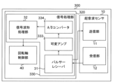
- FIG. 13 is a block diagram showing the configuration of a lubrication state determination device 300 according to Embodiment 3.
- the lubricating state determination device 300 according to the third embodiment is similar to the first embodiment in that it determines the state of the lubricating oil 3 based on the time change of the oil film thickness L obtained by tracking the amplitude peak of the echo signal. It is different from the lubricating state determination device 100 according to Except for this point, the lubrication state determination device 300 according to the third embodiment is the same as the lubrication state determination device 100 according to the first embodiment. 1 and 5 are therefore referred to in the following description.
- the lubrication state determination device 300 has a sensor 10 and a control device 320.
- the sensor 10 of Embodiment 3 may have a transmitting/receiving section 13 (that is, a configuration in which the transmitting section 11 and the receiving section 12 are integrated) as in FIG. 3 described above.
- the control device 320 has a signal processing section 330 and a rotating shaft control section 40 .
- the signal processing section 330 has a pulser receiver 31 , a signal waveform processing section 32 , a variable amplifier 333 as an amplifying section, and an A/D converter 334 .
- the correlation curve (see FIG. 6) between the oil film thickness L and the amplitude peak of the echo signal is stored in advance in the storage unit (not shown) of the control device 20.
- equipment 5 see FIG. 1
- various types of bearings 2 are used, and depending on the type of bearing 2, the above correlation curve may also differ. It is difficult to obtain a correlation curve for each bearing 2 used in equipment 5 .
- the signal waveform processing unit 32 of the lubricating state determination device 300 determines the state of the lubricating oil 3 based on the time change of the oil film thickness L obtained by tracking the amplitude peak of the echo signal.
- FIG. 14 is a flowchart showing an example of processing contents of the control device 320 of the lubrication condition determination device 300. As shown in FIG. 14
- step ST301 the pulser receiver 31 receives an echo signal of a predetermined length of time.
- step ST302 the variable amplifier 333 amplifies the echo signal output from the pulser receiver 31.
- step ST303 the A/D converter 334 converts the echo signal amplified in step ST302 into a digital signal.
- step ST304 the signal waveform processing section 32 filters out out-of-band noise in the echo signal converted into a digital signal in step ST303.
- step ST305 the signal waveform processing section 32 acquires the frequency spectrum of the echo signal by performing FFT processing on the noise-removed echo signal.
- step ST306 the signal waveform processing section 32 tracks the peak value of the amplitude component of a predetermined frequency in the frequency spectrum acquired in step ST305.
- FIG. 15(A) is a diagram showing the frequency spectrum of the echo signal acquired in step ST305 shown in FIG.
- the horizontal axis indicates frequency and the vertical axis indicates FFT amplitude.
- the solid line graph shows the frequency spectrum S1 of the echo signal at the first point in time.
- the graph indicated by the dashed-dotted line shows the frequency spectrum S2 of the echo signal at the second point in time after the first point in time.
- the amplitude at the peak frequency fp of the frequency spectrum S1 and the amplitude at the peak frequency fp of the frequency spectrum S2 are different from each other.
- the amplitudes at the peak frequencies of the frequency spectra S1 and S2 fluctuate as the rotating shaft 1 (see FIG. 1) rotates.
- FIG. 15(B) is a graph showing the tracking results of the peak values of the frequency spectra S1 and S2 shown in FIG. 15(A).
- the horizontal axis indicates time
- the vertical axis indicates the peak value of FFT amplitude.
- the peak value of the FFT amplitude on the vertical axis of FIG. 15(B) is proportional to the oil film thickness L. Therefore, the graph shown in FIG. 15(B) shows the change in the oil film thickness L over time.
- the graph shown in FIG. 15(B) indicates that the lubrication state between the rotating shaft 1 and the bearing 2 is normal. This is because the peak value of the FFT amplitude changes significantly over time.
- the amplitude of the echo signal after FFT processing also decreases.
- a substantially constant straight line graph in which the peak value of the FFT amplitude is small and does not change is obtained.
- the signal waveform processing unit 32 performs the rotation axis 1 and the bearing 2 is thin, and the lubrication state is determined to be poor.
- the graph shown in FIG. It may be a graph with small changes.
- step ST307 the signal waveform processing section 32 records a waveform signal indicating the tracking result of the peak value.
- step ST308 feature quantities are extracted from the waveform signal recorded for a predetermined time.
- the "feature amount" in step ST308 is, for example, the peak value of the FFT amplitude obtained by the FFT processing in step ST305 described above, the normalized value of the peak value, the time-differentiated value of the peak value, or It is a value obtained by time-integrating the peak value.
- the signal waveform processing section 32 stores the feature quantity extracted in step ST308 in the database together with the device information indicating the information of the device 5.
- the device information is, for example, information indicating the types of the rotating shaft 1, the bearings 2, and the lubricating oil 3, and information indicating the product number of the device 5 and the like.
- step ST310 the signal waveform processing section 32 machine-learns the information saved in the database in step ST309. Note that the processing of steps ST309 and ST310 may be omitted.
- step ST311 the signal waveform processing unit 32 determines whether the lubrication state between the rotating shaft 1 and the bearing 2, in other words, the rotation of the device 5, is good or bad based on the change in the peak value of the FFT amplitude tracked in step ST306. Judgment of quality is made.
- the signal waveform processing section 32 may determine whether or not seizure occurs in at least one of the rotary shaft 1 and the bearing 2.
- the extraction of the feature amount in step ST310 described above may be performed simultaneously with the tracking of the peak value in step ST306.
- the tracking of the peak value in step ST306 is performed not by tracking one peak value, in other words, by tracking the local maximum points P1 and P2 of the frequency spectra S1 and S2 shown in FIG. 15A, but by tracking one frequency. Multiple peak values in the spectrum may be tracked.
- the signal waveform processing unit 32 it may be determined that the lubrication state during is bad or that the sensor 10 is abnormal. In this case, the rotating shaft control section 40 may stop the rotation of the rotating shaft 1 .
- the signal waveform processing unit 32 detects the oil film thickness L between the rotating shaft 1 and the bearing 2 based on the tracking result of the amplitude peak value of the echo signal. This makes it possible to determine the state of the lubricating oil 3 even if it is difficult to acquire in advance the correlation curve that indicates the correlation between the oil film thickness L and the amplitude peak of the echo signal.
- the signal waveform processing unit 32 can make a determination following changes in the sound velocity c of the ultrasonic wave U1 (see FIG. 5) due to temperature changes in the bearing 2 and the lubricating oil 3. . Therefore, the signal waveform processing unit 32 can determine the state of the lubricating oil 3 existing between the rotating shaft 1 and the bearing 2 over a wide temperature range.
Landscapes
- Physics & Mathematics (AREA)
- Acoustics & Sound (AREA)
- Health & Medical Sciences (AREA)
- Life Sciences & Earth Sciences (AREA)
- Chemical & Material Sciences (AREA)
- Analytical Chemistry (AREA)
- Biochemistry (AREA)
- General Health & Medical Sciences (AREA)
- General Physics & Mathematics (AREA)
- Immunology (AREA)
- Pathology (AREA)
- Investigating Or Analyzing Materials By The Use Of Ultrasonic Waves (AREA)
Abstract
潤滑状態判定装置(100)は、回転軸(1)と、回転軸(1)を支持する軸受(2)と、互いに向き合う回転軸(1)の第1の面(1a)と軸受(2)の第2の面(2b)との間に存在する潤滑油(3)とを有する機器(5)において、潤滑油(3)の状態を判定する。潤滑状態判定装置(100)は、超音波又は音波である音響出力波を送信する送信部(11)と、受信した音響出力波の反射波である音響入力波に応じた振幅の信号である第1の信号及び回転軸(1)と軸受(2)との接触に起因するアコースティックエミッション波の周波数帯の信号である第2の信号を受信する受信部(12)と、を有するセンサ(10)と、第1の信号及び第2の信号に基づいて潤滑油(3)の状態を判定する制御部(20)とを備える。
Description
本開示は、回転軸と軸受との間に存在する潤滑油の状態を判定する潤滑状態判定装置に関する。
金属材料から形成された部材同士が摺動する部分に存在する潤滑油の状態を判定する装置が知られている。例えば、特許文献1及び非特許文献1を参照。
特許文献1の装置は、エンジンのピストンとシリンダとの間に存在する潤滑油の状態を判定する。特許文献1の装置は、ピストンとシリンダとが潤滑油を介さずに接触したときに発生するアコースティックエミッション波を検出する圧電素子を有する。
非特許文献1の装置は、超音波を用いて、回転軸と焼結軸受との間に存在する潤滑油の状態を判定する。非特許文献1の装置は、焼結軸受の外周面で反射した超音波の反射波と、回転軸の外周面で反射した超音波の反射波との干渉波を計測することによって、潤滑油の油膜厚を測定している。
「超音波法による多孔質焼結含油軸受の油膜厚さ測定(温度補正法による測定精度の向上検討)」、設計工学、Vol.52、No.12、2017、pp.737-752
しかしながら、回転軸と軸受との間に存在する潤滑油の状態は、潤滑油の濃度及び回転軸における表面処理の方法などによって異なるため、特許文献1の装置及び非特許文献1の装置では、潤滑油の状態を正確に判定することが困難であった。
本開示は、回転軸と軸受との間に存在する潤滑油の状態の判定精度を向上させることを目的としている。
本開示の一態様に係る潤滑状態判定装置は、回転軸と、前記回転軸を支持する軸受と、互いに向き合う前記回転軸の第1の面と前記軸受の第2の面との間に存在する潤滑油とを有する機器において、前記潤滑油の状態を判定する潤滑状態判定装置であって、超音波又は音波である音響出力波を送信する送信部と、受信した前記音響出力波の反射波である音響入力波に応じた振幅の信号である第1の信号及び前記回転軸と前記軸受との接触に起因するアコースティックエミッション波の周波数帯の信号である第2の信号を受信する受信部と、を有するセンサと、前記第1の信号及び前記第2の信号に基づいて前記潤滑油の状態を判定する制御部とを備える、ことを特徴とする。
本開示によれば、回転軸と軸受との間に存在する潤滑油の状態の判定精度を向上させることができる。
以下に、本開示の実施の形態に係る潤滑状態判定装置を、図面を参照しながら説明する。以下の実施の形態は、例にすぎず、実施の形態を適宜組み合わせること及び各実施の形態を適宜変更することが可能である。
《実施の形態1》
〈潤滑状態判定装置100の構成〉
図1は、実施の形態1に係る潤滑状態判定装置100の構成及び潤滑状態判定装置100の判定対象の機器5の構成を概略的に示す構成図である。潤滑状態判定装置100は、回転軸1と軸受2と潤滑油3とを有する機器5において、回転軸1と軸受2との間に存在する潤滑油3の状態(以下、「潤滑状態」とも呼ぶ。)を判定する。潤滑状態判定装置100は、例えば、回転軸1が軸線Axを中心に回転しているときの潤滑油3の状態を判定する。なお、潤滑状態判定装置100は、回転軸1が回転していないときの潤滑油3の状態を判定することもできる。
〈潤滑状態判定装置100の構成〉
図1は、実施の形態1に係る潤滑状態判定装置100の構成及び潤滑状態判定装置100の判定対象の機器5の構成を概略的に示す構成図である。潤滑状態判定装置100は、回転軸1と軸受2と潤滑油3とを有する機器5において、回転軸1と軸受2との間に存在する潤滑油3の状態(以下、「潤滑状態」とも呼ぶ。)を判定する。潤滑状態判定装置100は、例えば、回転軸1が軸線Axを中心に回転しているときの潤滑油3の状態を判定する。なお、潤滑状態判定装置100は、回転軸1が回転していないときの潤滑油3の状態を判定することもできる。
図1に示される機器5は、例えば、冷凍サイクル装置(例えば、空気調和装置)に備えられた圧縮機などの回転機械である。軸受2は、例えば、円筒状の滑り軸受(すなわち、ジャーナル軸受)である。潤滑油3は、第1の面としての回転軸1の外周面1aと第2の面としての軸受2の内周面2bとの間に存在している。回転軸1の外周面1aは、回転軸1と潤滑油3との境界面であり、軸受2の内周面2bは、軸受2と潤滑油3との境界面である。なお、軸受2は、滑り軸受に限らず、転がり軸受であってもよく、潤滑状態判定装置100は、回転軸1と当該転がり軸受との間の潤滑油3の状態を判定してもよい。
図2は、実施の形態1に係る潤滑状態判定装置100の構成を示すブロック図である。図1及び2に示されるように、潤滑状態判定装置100は、センサ10と、制御部としての制御装置20とを有する。
センサ10は、例えば、超音波センサである。実施の形態1では、センサ10は、軸受2に備えられている。図1に示す例では、センサ10の一部が、軸受2の内部に固定されている。なお、後述する図12に示されるように、センサ10は、回転軸201に備えられていてもよい。
図2に示されるように、センサ10は、送信部11と、受信部12とを有する。送信部11及び受信部12はそれぞれ、圧電素子(例えば、セラミック振動子)を有する。送信部11は、後述するパルサーレシーバ31から送信された駆動信号(電圧信号)によって発生した超音波を潤滑油3に向けて送信する。受信部12は、送信部11から送信された超音波の反射波の干渉波を受信する。受信部12は、当該干渉波に応じた振幅の信号をパルサーレシーバ31に出力する。なお、干渉波については、後述する図5を用いて説明する。
図3は、実施の形態1に係る潤滑状態判定装置100の構成の他の例を示すブロック図である。図3に示されるように、センサ10は、図2に示される送信部11及び受信部12が一体化された送受信部13を有していてもよい。送受信部13は、パルサーレシーバ31から送信された駆動信号によって発生した超音波を潤滑油3に向けて送信し、当該超音波の反射波の干渉波を受信する。
制御装置20は、信号処理部30と、回転軸制御部40とを有する。
信号処理部30は、パルサーレシーバ31と、信号波形処理部32とを有する。パルサーレシーバ31は、送信部11を駆動させる駆動信号を送信し、且つ受信部12から出力された信号を受信する。信号波形処理部32は、パルサーレシーバ31から出力された信号に基づいて潤滑油3(図1参照)の状態を判定する。
回転軸制御部40は、信号波形処理部32における判定結果に基づいて、機器5における回転軸1(図1参照)の回転動作を制御する。具体的には、信号波形処理部32が回転軸1と軸受2との間の潤滑状態が正常であると判定した場合には、回転軸制御部40は、回転軸1の回転を継続させる。一方、信号波形処理部32が回転軸1と軸受2との間の潤滑状態が不良であると判定した場合には、回転軸制御部40は、回転軸1の回転速度を低下又は回転軸1の回転を停止させる。なお、潤滑状態が不良であると判定された場合に、回転軸制御部40は、回転軸1における回転負荷の調整を行ってもよい。
図4(A)は、潤滑状態判定装置100の制御装置20のハードウェア構成の一例を概略的に示す図である。図4(A)に示されるように、潤滑状態判定装置100の制御装置20は、例えば、ソフトウェアとしてのプログラムを格納する記憶装置としてのメモリ20aと、メモリ20aに格納されたプログラムを実現する情報処理部としてのプロセッサ20bとを用いて(例えば、コンピュータによって)実現することができる。なお、制御装置20の一部が、図4(A)に示されるメモリ20aと、プログラムを実行するプロセッサ20bとによって実現されてもよい。また、制御装置20は、電気回路によって実現されてもよい。
図4(B)は、潤滑状態判定装置100の制御装置20のハードウェア構成の他の例を概略的に示す図である。図4(B)に示されるように、制御装置20は、単一回路又は複合回路等の専用のハードウェアとしての処理回路20cを用いて実現されていてもよい。この場合、制御装置20の機能は、処理回路20cで実現される。
〈油膜の厚さの測定〉
次に、図5を用いて、超音波を用いた潤滑油3の油膜の厚さ(以下、「油膜厚L」と呼ぶ。)の測定について説明する。図5は、図1及び2に示されるセンサ10から送信された超音波U1の反射波による油膜厚Lの測定原理を説明する説明図である。
次に、図5を用いて、超音波を用いた潤滑油3の油膜の厚さ(以下、「油膜厚L」と呼ぶ。)の測定について説明する。図5は、図1及び2に示されるセンサ10から送信された超音波U1の反射波による油膜厚Lの測定原理を説明する説明図である。
図5に示されるように、センサ10から送信された超音波U1は、軸受2の内部を透過して、軸受2の内周面2bで内部反射する。また、超音波U1は、軸受2及び潤滑油3を透過して、回転軸1の外周面1aで反射する。図5において、軸受2の内周面2bで内部反射した超音波U1の反射波をR1、回転軸1の外周面1aで反射した超音波U1の反射波をR2とする。図2に示される受信部12(又は、図3に示される送受信部13)は、反射波R1、R2の干渉波を受信する。なお、センサ10は、超音波U1に代えて、例えば、振動数が20kHzよりやや小さい音波を送信してもよい。言い換えれば、図2に示される送信部11は、超音波又は音波である音響出力波を送信し、受信部12は、音響出力波の反射波である音響入力波を受信する。
ここで、超音波U1の波長(単位:mm)をλ、軸受2内での音速(単位:m/s)をc、駆動周波数(単位:MHz)をfとしたとき、波長λは、以下の式(1)で示される。
λ=c/f (1)
例えば、音速c=5600m/s、駆動周波数f=2MHzであるとき、波長λは、2.8mmである。なお、「駆動周波数」とは、図2に示される送信部11(又は、図3に示される送受信部13)のセラミック振動子に印加される電圧信号の周波数である。
λ=c/f (1)
例えば、音速c=5600m/s、駆動周波数f=2MHzであるとき、波長λは、2.8mmである。なお、「駆動周波数」とは、図2に示される送信部11(又は、図3に示される送受信部13)のセラミック振動子に印加される電圧信号の周波数である。
軸受2の強度を十分に確保するために、軸受2の材質が、例えば、鉄であるとき、図5において、軸受2と潤滑油3との境界面である軸受2の内周面2bからセンサ10までの距離(以下、「離隔距離」とも呼ぶ。)は、超音波U1の1波長以上の距離である。具体的には、離隔距離は、2.8mm以上である。なお、離隔距離は、機器5の負荷及び軸受2の形状などに応じて、適宜変更してもよい。
パルサーレシーバ31(図2参照)は、受信部12から出力された反射波R1、R2の干渉波に応じた振幅の信号である第1の信号(以下、「エコー信号」とも呼ぶ。)を、信号波形処理部32に出力する。信号波形処理部32(図2参照)は、エコー信号に基づいて干渉波の大きさ(強度)を検出し、当該干渉波の大きさに基づいて油膜厚Lを測定する。
次に、図6を用いて、油膜厚Lと干渉波の大きさとの関係について説明する。図6は、油膜厚Lと干渉波の大きさとの関係を示すグラフである。図6において、縦軸は、干渉波の波形成分中のピーク値である振幅ピークを示し、横軸は、油膜厚L(単位:μm)を示す。図6において、破線で示されるグラフは、油膜厚Lとエコー信号の振幅ピークとの理想的な関係を示す。また、図6に示される複数のプロットはそれぞれ、実際の測定値を示す。
図6に示されるように、エコー信号の振幅ピークは、油膜厚Lに比例して大きくなる。言い換えれば、油膜厚Lが厚ければ振幅ピークは大きく、油膜厚Lが薄ければ振幅ピークは小さい。これにより、信号波形処理部32は、エコー信号の振幅ピークに基づいて、回転軸1と軸受2との間に存在する潤滑油3の状態を判定することができる。
〈温度上昇によるエコー信号の変化〉
次に、図7から9を用いて、軸受2及び潤滑油3の温度上昇によるエコー信号の変化について説明する。図7は、図1に示されるセンサ10から出力された正常時のエコー信号の波形を示す基準波形W0と、エコー信号の異常時の第1の波形(以下、「第1の異常波形」と呼ぶ。)W1とを示すグラフである。図7において、基準波形W0は破線のグラフによって表されていて、第1の異常波形W1は実線のグラフによって表されている。また、図7、後述する図8及び9において、横軸は、時間(単位:μs)を示し、縦軸は、エコー信号の振幅を示す。
次に、図7から9を用いて、軸受2及び潤滑油3の温度上昇によるエコー信号の変化について説明する。図7は、図1に示されるセンサ10から出力された正常時のエコー信号の波形を示す基準波形W0と、エコー信号の異常時の第1の波形(以下、「第1の異常波形」と呼ぶ。)W1とを示すグラフである。図7において、基準波形W0は破線のグラフによって表されていて、第1の異常波形W1は実線のグラフによって表されている。また、図7、後述する図8及び9において、横軸は、時間(単位:μs)を示し、縦軸は、エコー信号の振幅を示す。
基準波形W0は、回転軸1と軸受2との間の油膜厚Lが正常であって、且つ軸受2(又は潤滑油3)の温度が30℃であるときに検出されたエコー信号の波形である。ここで、「油膜厚Lが正常」とは、例えば、油膜厚Lが予め定められた設定値より厚いことをいう。また、第1の異常波形W1は、油膜厚Lが不良であって潤滑油3の温度が30℃であるときに検出されたエコー信号の波形である。言い換えれば、第1の異常波形W1は、油膜厚Lが設定値より薄いことで回転軸1に軸受2が接近し、回転軸1及び軸受2の少なくとも一方に焼き付きが発生する前のエコー信号の波形を示す。図7に示されるように、例えば、時間が1.0μsから3.0μsまでの範囲内では、第1の異常波形W1におけるエコー信号の振幅は、基準波形W0におけるエコー信号の振幅より小さい。
図8は、基準波形W0と、エコー信号の異常時の第2の波形(以下、「第2の異常波形」と呼ぶ。)W2とを示すグラフである。図9は、基準波形W0と、エコー信号の異常時の第3の波形(以下、「第3の異常波形」と呼ぶ。)W3とを示すグラフである。図8に示される第2の異常波形W2は、油膜厚Lが設定値より薄く且つ軸受2(又は潤滑油3)の温度が70℃であるときに検出されたエコー信号の波形を示す。また、図9に示される第3の異常波形W3は、油膜厚Lが設定値より薄く且つ軸受2(又は潤滑油3)の温度が120℃であるときに検出されたエコー信号の波形を示す。図8及び9に示されるように、時間が1.0μsから3.0μsまでの範囲内では、第2の異常波形W2におけるエコー信号の振幅及び第3の異常波形W3におけるエコー信号の振幅はそれぞれ、基準波形W0におけるエコー信号の振幅より小さい。
また、図7において、第1の異常波形W1が受信された時点をt1、図8において、第2の異常波形W2が受信された時点をt2としたとき、時点t2は時点t1より早い。更に、図9において、第3の異常波形W3が受信された時点をt3としたとき、時点t3は、図8に示される時点t2より早い。これは、超音波U1が伝搬する媒質中の温度、すなわち、軸受2及び潤滑油3の温度の影響を受けて、超音波U1の音速cが変化したためである。具体的には、軸受2及び潤滑油3の温度が上昇するにつれて、音速cは速くなる。そのため、図7から9に示されるように、軸受2及び潤滑油3の温度が上昇するほど、第2の異常波形W2及び第3の異常波形W3のそれぞれが、パルサーレシーバ31に受信された時点が早くなる。
このように、軸受2及び潤滑油3の温度上昇によって、超音波U1の音速cが変化する。従来の装置は、例えば、図7に示される第1の異常波形W1において選択したピーク値を追跡することで、油膜厚Lの測定を実現していた。しかしながら、実機において、エコー信号のピーク値を常時追跡することは困難である。また、潤滑油3が枯渇した状態、すなわち、焼き付きが発生する直前の状態では、回転軸1及び軸受2の温度上昇が想定される。この場合、エコー信号の信号強度レベルの低下又はエコー信号の消失が発生するため、油膜厚Lの測定が困難である。よって、従来の装置では、エコー信号のみに基づいて焼き付きの予兆があるか否かを判定することが困難である。また、機器5が圧縮機である場合、ガス冷媒によって潤滑油が発泡する可能性があることによっても、エコー信号の信号強度レベルの低下又はエコー信号の消失が発生する。
〈焼き付きの予兆の有無の判定〉
次に、潤滑状態判定装置100において、回転軸1及び軸受2における焼き付きの予兆の有無の判定方法について説明する。一般的に、超音波センサのセラミック振動子は、駆動周波数fと同じ共振周波数を持つ。受信感度を高めるために、超音波センサでは、共振周波数と同じ周波数におけるエコー信号が検出される。共振周波数以外の周波数におけるエコー信号は、大きく減衰するため、油膜厚Lの測定に用いられていなかった。
次に、潤滑状態判定装置100において、回転軸1及び軸受2における焼き付きの予兆の有無の判定方法について説明する。一般的に、超音波センサのセラミック振動子は、駆動周波数fと同じ共振周波数を持つ。受信感度を高めるために、超音波センサでは、共振周波数と同じ周波数におけるエコー信号が検出される。共振周波数以外の周波数におけるエコー信号は、大きく減衰するため、油膜厚Lの測定に用いられていなかった。
本願発明者は、セラミック振動子の共振周波数以下の低い周波数帯域に着目した。本願発明者による研究の結果、セラミック振動子の共振周波数以下の低い周波数帯の信号、具体的には、回転軸1と軸受2との接触に起因するアコースティックエミッション波の周波数帯の第2の信号(以下、「AE信号」とも呼ぶ。)が、超音波センサによって得られることが判明した。すなわち、実施の形態1では、単一のセンサ10が、エコー信号及びAE信号の両方を受信する。なお、実施の形態1のセンサ10に備えられたセラミック振動子の共振周波数は、例えば、2MHzである。
図10は、センサ10によって検出されたAE信号の周波数スペクトルを示すグラフである。図10は、センサ10によって検出されたAE信号にFFT(Fast Fourier Transform)処理を行った後の解析結果を示す。図10において、横軸は、周波数(単位:Hz)を示し、縦軸は、振幅ピークを示す。
図10に示されるように、セラミック振動子の共振周波数2MHzより低い周波数帯である100kHz周辺、具体的には、20kHz周辺において、軸受2の打音時のAE信号が検出されている。なお、「軸受2の打音時」とは、回転軸1と軸受2とが潤滑油3を介さずに摺動して、音が発生しているときをいう。
信号波形処理部32は、AE信号を増幅し、特徴量を抽出する。具体的には、信号波形処理部32は、パルサーレシーバ31を介してセンサ10から出力された共振周波数以下の信号(すなわち、AE信号)をFFT処理した後に、大きな振幅ピークを持つ周波数を抽出する。
信号波形処理部32は、例えば、AE信号の振幅が予め定められた第2の閾値である閾値Th2以上であるか否かを判定する。これにより、回転軸1と軸受2との間の潤滑油3の枯渇などによって、エコー信号の信号強度レベルの低下又はエコー信号の消失が発生した場合でも、信号波形処理部32は、AE信号に基づいて焼き付きの予兆の有無を判定することができる。よって、焼き付きによる機器5の故障を予め防止することができるため、機器5の安全性を向上させることができる。また、潤滑状態判定装置100は、AE信号を受信する他のセンサ(例えば、加速度センサ)を設けずに、焼き付きの予兆の有無を判定することができる。よって、潤滑状態判定装置100における部品点数を削減することができる。なお、信号波形処理部32は、センサ10から出力された信号をFFT処理した後に自己相関処理を行うことで、回転軸1及び軸受2における焼き付きの予兆の有無を判定してもよい。例えば、信号波形処理部32は、自己相関処理によって算出された自己相関値が閾値より大きい場合に、焼き付きの予兆が有ると判定する。
〈制御装置20の処理内容〉
次に、図11を用いて、潤滑状態判定装置100の制御装置20の処理内容について説明する。図11は、潤滑状態判定装置100の制御装置20の処理内容の一例を示すフローチャートである。
次に、図11を用いて、潤滑状態判定装置100の制御装置20の処理内容について説明する。図11は、潤滑状態判定装置100の制御装置20の処理内容の一例を示すフローチャートである。
先ず、ステップST1において、信号波形処理部32は、パルサーレシーバ31から出力されたエコー信号の振幅(例えば、振幅ピーク)が予め定められた第1の閾値である閾値Th1より小さいか否かを判定する第1の判定を行う。信号波形処理部32は、エコー信号の振幅ピークが閾値Th1より小さいと判定した場合(つまり、ステップST1において、判定がYesである場合)、処理をステップST2へ進める。なお、ステップST1において、信号波形処理部32は、エコー信号の振幅ピークの積分値が予め定められた閾値以下であるか否かを判定してもよい。
ステップST2において、信号波形処理部32は、パルサーレシーバ31から出力された信号のうちAE信号の振幅(例えば、振幅ピーク)が閾値Th2以上であるか否かを判定する第2の判定を行う。信号波形処理部32は、AE信号の振幅ピークが閾値Th2以上であると判定した場合(つまり、ステップST2において、判定がYesである場合)、処理をステップST3へ進める。なお、ステップST2において、信号波形処理部32は、AE信号の振幅ピークの積分値が予め定められた閾値以であるか否かを判定してもよい。
ステップST3において、回転軸制御部40は、回転軸1の回転速度を低下又は回転軸1の回転を停止させる。これにより、焼き付きによる機器5の故障を予め防止することができるため、機器5の安全性を向上させることができる。
なお、信号波形処理部32は、ステップST1における第1の判定処理と、ステップST2における第2の判定処理とを並列に行ってもよい。これにより、信号波形処理部32は、エコー信号の信号強度レベルの低下又はエコー信号の消失が発生した場合、直ちにAE信号に基づいて潤滑油3の状態を判定することができる。よって、回転軸1及び軸受2の少なくとも一方に焼き付きの予兆が有るか否かを早期に判定することができる。この場合、回転軸制御部40は、エコー信号の振幅ピークが閾値Th1より小さく、且つAE信号の振幅ピークが閾値Th2以上である場合に、回転軸1の回転速度を低下又は回転軸1の回転を停止させる。
〈実施の形態1の効果〉
以上に説明した実施の形態1によれば、潤滑状態判定装置100は、エコー信号及びAE信号を受信するセンサ10と、センサ10から出力されたエコー信号及びAE信号に基づいて潤滑油3の状態を判定する制御装置20とを有する。これにより、潤滑油3の枯渇などによってエコー信号の信号強度レベルの低下又はエコー信号の消失が発生した場合であっても、AE信号に基づいて潤滑油3の状態を判定することができる。言い換えれば、潤滑状態判定装置100は、エコー信号の振幅ピーク(又は当該振幅ピークの積分値)が0に近い値であっても、AE信号に基づいて潤滑油3の状態を判定することができる。よって、実施の形態1によれば、潤滑油3の状態の判定精度を向上させることができる。
以上に説明した実施の形態1によれば、潤滑状態判定装置100は、エコー信号及びAE信号を受信するセンサ10と、センサ10から出力されたエコー信号及びAE信号に基づいて潤滑油3の状態を判定する制御装置20とを有する。これにより、潤滑油3の枯渇などによってエコー信号の信号強度レベルの低下又はエコー信号の消失が発生した場合であっても、AE信号に基づいて潤滑油3の状態を判定することができる。言い換えれば、潤滑状態判定装置100は、エコー信号の振幅ピーク(又は当該振幅ピークの積分値)が0に近い値であっても、AE信号に基づいて潤滑油3の状態を判定することができる。よって、実施の形態1によれば、潤滑油3の状態の判定精度を向上させることができる。
また、実施の形態1によれば、エコー信号の振幅ピーク(又は当該振幅ピークの積分値)が予め定められた閾値Th1より小さい場合には、信号波形処理部32は、センサ10によって検出された信号のうち、AE信号を抽出する。これにより、潤滑油3の枯渇などによって、エコー信号の信号強度レベルの低下又はエコー信号の消失が発生した場合でも、制御装置20は、AE信号に基づいて回転軸1及び軸受2のうちの少なくとも一方における焼き付きの予兆の有無を判定することができる。
また、実施の形態1によれば、制御装置20は、AE信号の振幅ピークが閾値Th2以上であると判定した場合には、回転軸1の回転速度を低下又は回転軸1の回転を停止させる。これにより、回転軸1及び軸受2の少なくとも一方の焼き付きによる機器5の故障を予め防止することができるため、機器5の安全性を向上させることができる。
また、実施の形態1によれば、センサ10は、軸受2に備えられている。これにより、潤滑油3の枯渇などによって、エコー信号の信号強度レベルの低下又はエコー信号の消失が発生した場合でも、センサ10は、回転軸1が回転しているときの回転軸1と軸受2との接触に起因するAE信号を検出し易くなる。
《実施の形態2》
図12は、実施の形態2に係る潤滑状態判定装置200の構成及び潤滑状態判定装置200の判定対象の機器205の構成を概略的に示す構成図である。図12において、図1に示される構成要素と同一又は対応する構成要素には、図1に示される符号と同じ符号が付される。実施の形態2に係る潤滑状態判定装置200は、センサ10が回転軸201に備えられている点で、実施の形態1に係る潤滑状態判定装置100と相違する。これ以外の点については、実施の形態2に係る潤滑状態判定装置200は、実施の形態1に係る潤滑状態判定装置100と同じである。そのため、以下の説明では、図2を参照する。
図12は、実施の形態2に係る潤滑状態判定装置200の構成及び潤滑状態判定装置200の判定対象の機器205の構成を概略的に示す構成図である。図12において、図1に示される構成要素と同一又は対応する構成要素には、図1に示される符号と同じ符号が付される。実施の形態2に係る潤滑状態判定装置200は、センサ10が回転軸201に備えられている点で、実施の形態1に係る潤滑状態判定装置100と相違する。これ以外の点については、実施の形態2に係る潤滑状態判定装置200は、実施の形態1に係る潤滑状態判定装置100と同じである。そのため、以下の説明では、図2を参照する。
実施の形態2では、センサ10は、機器205の回転軸201に備えられている。具体的には、センサ10は、回転軸201の内部に備えられている。図12に示す例では、回転軸201は、z軸方向に延びる中空部としての孔201cが設けられていて、センサ10は、当該孔201cに設けられている。これにより、上述した実施の形態1のように、センサ10が軸受2に取り付けられている構成と比較して、回転軸201の内部の全周に亘ってエコー信号及びAE信号を検出することができる。よって、油膜厚Lの判定及び焼き付きの予兆の有無の判定を早期に実現することができる。
図12に示されるように、センサ10が孔201cに設けられている場合、センサ10とパルサーレシーバ31とを繋ぐ信号線は、例えば、スリップリングによって接続されている。なお、孔201cは、回転軸201を軸線Axの方向に貫通していてもよいし、貫通していなくてもよい。また、孔201cは、回転軸201の内部を径方向に延びていてもよい。また、センサ10は、回転軸201の外周面201aに備えられていてもよい。更に、センサ10は、回転軸201の外周面201aに設けられた凹部に埋め込まれていてもよい。
〈実施の形態2の効果〉
以上に説明した実施の形態2によれば、センサ10は、回転軸201に備えられている。これにより、潤滑油3の枯渇などによって、エコー信号の信号強度レベルの低下又はエコー信号の消失が発生した場合でも、センサ10は、回転軸201が回転しているときの回転軸201と軸受2との接触に起因するAE信号を検出し易くなる。
以上に説明した実施の形態2によれば、センサ10は、回転軸201に備えられている。これにより、潤滑油3の枯渇などによって、エコー信号の信号強度レベルの低下又はエコー信号の消失が発生した場合でも、センサ10は、回転軸201が回転しているときの回転軸201と軸受2との接触に起因するAE信号を検出し易くなる。
また、実施の形態2によれば、センサ10は、回転軸201の内部に備えられている。これにより、実施の形態1のように、センサ10が軸受2に備えられている構成(図1参照)と比較して、回転軸201内部の全周に亘ってエコー信号及びAE信号を検出することができる。よって、油膜厚Lの判定並びに回転軸201及び軸受2についての焼き付きの判定を早期に検出することができる。
《実施の形態3》
図13は、実施の形態3に係る潤滑状態判定装置300の構成を示すブロック図である。実施の形態3に係る潤滑状態判定装置300は、エコー信号の振幅ピークを追跡することで得られた油膜厚Lの時間変化に基づいて潤滑油3の状態を判定する点で、実施の形態1に係る潤滑状態判定装置100と相違する。これ以外の点については、実施の形態3に係る潤滑状態判定装置300は、実施の形態1に係る潤滑状態判定装置100と同じである。そのため、以下の説明では、図1及び5を参照する。
図13は、実施の形態3に係る潤滑状態判定装置300の構成を示すブロック図である。実施の形態3に係る潤滑状態判定装置300は、エコー信号の振幅ピークを追跡することで得られた油膜厚Lの時間変化に基づいて潤滑油3の状態を判定する点で、実施の形態1に係る潤滑状態判定装置100と相違する。これ以外の点については、実施の形態3に係る潤滑状態判定装置300は、実施の形態1に係る潤滑状態判定装置100と同じである。そのため、以下の説明では、図1及び5を参照する。
図13に示されるように、潤滑状態判定装置300は、センサ10と、制御装置320とを有する。なお、実施の形態3のセンサ10は、上述した図3と同様に、送受信部13(すなわち、送信部11及び受信部12が一体化された構成)を有していてもよい。
制御装置320は、信号処理部330と、回転軸制御部40とを有する。信号処理部330は、パルサーレシーバ31と、信号波形処理部32と、増幅部としての可変アンプ333と、A/Dコンバータ334とを有する。
ここで、上述した実施の形態1では、油膜厚Lとエコー信号の振幅ピークとの相関曲線(図6参照)は、制御装置20の記憶部(図示せず)に予め記憶されている。しかしながら、機器5(図1参照)では、様々な種類の軸受2が用いられ、軸受2の種類に応じて、上記相関曲線も異なる可能性がある。機器5に用いられる軸受2毎に、相関曲線を取得することは困難である。潤滑状態判定装置300の信号波形処理部32は、エコー信号の振幅ピークを追跡することで得られた油膜厚Lの時間変化に基づいて、潤滑油3の状態を判定する。
〈制御装置320の処理内容〉
次に、図14を用いて、潤滑状態判定装置300における制御装置320の処理内容について説明する。図14は、潤滑状態判定装置300の制御装置320の処理内容の一例を示すフローチャートである。
次に、図14を用いて、潤滑状態判定装置300における制御装置320の処理内容について説明する。図14は、潤滑状態判定装置300の制御装置320の処理内容の一例を示すフローチャートである。
先ず、ステップST301において、パルサーレシーバ31は、所定の時間長のエコー信号を受信する。
ステップST302において、可変アンプ333は、パルサーレシーバ31から出力されたエコー信号を増幅する。
ステップST303において、A/Dコンバータ334は、ステップST302において増幅されたエコー信号をデジタル信号に変換する。
ステップST304において、信号波形処理部32は、ステップST303においてデジタル信号に変換されたエコー信号のうちの帯域外のノイズを、フィルタリングによって除去する。
ステップST305において、信号波形処理部32は、ノイズ除去されたエコー信号をFFT処理することにより、エコー信号の周波数スペクトルを取得する。
ステップST306において、信号波形処理部32は、ステップST305において取得された周波数スペクトルのうちの所定の周波数の振幅成分についてのピーク値を追跡する。
ここで、ステップST306におけるピーク値の追跡の詳細について説明する。図15(A)は、図14に示されるステップST305において取得されたエコー信号の周波数スペクトルを示す図である。図15(A)において、横軸は周波数を示し、縦軸はFFT振幅を示す。図15(A)において、実線で示されるグラフは、第1の時点におけるエコー信号の周波数スペクトルS1を示す。また、一点鎖線で示されるグラフは、第1の時点から時間が経過した第2の時点におけるエコー信号の周波数スペクトルS2を示す。
図15(A)に示されるように、周波数スペクトルS1のピーク周波数fpにおける振幅と、周波数スペクトルS2のピーク周波数fpにおける振幅とは、互いに異なる。このように、回転軸1(図1参照)の回転に伴い、周波数スペクトルS1、S2のピーク周波数における振幅が変動する。
図15(B)は、図15(A)に示される周波数スペクトルS1、S2のピーク値の追跡結果を示すグラフである。図15(B)において、横軸は時間を示し、縦軸はFFT振幅のピーク値を示す。ここで、図15(B)の縦軸のFFT振幅のピーク値は、油膜厚Lに比例する。そのため、図15(B)に示されるグラフは、油膜厚Lの時間変化を示す。図15(B)に示されるグラフは、回転軸1と軸受2との間の潤滑状態が正常であることを示す。これは、時間が経過するにつれて、FFT振幅のピーク値が大きく変化しているためである。
一方、回転軸1と軸受2との間の油膜厚Lが減少した場合、FFT処理後のエコー信号の振幅も減少する。この場合、回転軸1が回転しているときの振幅の大きさが変化しないため、例えば、FFT振幅のピーク値が小さい値で且つ当該ピーク値が変化しない、概ね一定の直線のグラフが得られる。このように、周波数スペクトルS1、S2のピーク値の追跡結果によって、小さいピーク値(例えば、閾値より小さいピーク値)が維持されるグラフが得られた場合、信号波形処理部32は、回転軸1と軸受2との間の油膜厚Lが薄く、潤滑状態が不良であると判定する。なお、回転軸1と軸受2との間の油膜厚Lが減少した場合、図15(B)に示されるグラフは、FFT振幅のピーク値が時間変化に伴って徐々に低下するグラフ、又は振幅変化の小さいグラフになる場合もある。
図14に戻って、ステップST307以降の処理内容について説明する。ステップST307において、信号波形処理部32は、ピーク値の追跡結果を示す波形信号を記録する。
ステップST308において、所定の時間記録された波形信号から特徴量を抽出する。ここで、ステップST308における「特徴量」は、例えば、上述したステップST305のFFT処理によって得られたFFT振幅のピーク値、当該ピーク値を規格化した値、当該ピーク値を時間微分した値、又は当該ピーク値を時間積分した値などである。
ステップST309において、信号波形処理部32は、ステップST308において抽出された特徴量を、機器5の情報を示す機器情報と共にデータベースに保存する。なお、機器情報とは、例えば、回転軸1、軸受2及び潤滑油3の種類などを示す情報、並びに機器5の品番などを示す情報である。
ステップST310において、信号波形処理部32は、ステップST309においてデータベースに保存された情報を機械学習する。なお、ステップST309及びST310の処理は、省略されてもよい。
ステップST311において、信号波形処理部32は、ステップST306において追跡されたFFT振幅のピーク値の変化に基づいて、回転軸1と軸受2の間の潤滑状態の良否、言い換えれば、機器5における回転の品質の良否についての判定を行う。なお、ステップST311において、信号波形処理部32は、回転軸1及び軸受2の少なくとも一方についての焼き付きの有無を判定してもよい。
なお、上述したステップST310における特徴量の抽出は、ステップST306におけるピーク値の追跡と同時に行われてもよい。また、ステップST306におけるピーク値の追跡は、1つのピーク値、言い換えれば、図15(A)に示される周波数スペクトルS1、S2のそれぞれの極大点P1、P2を追跡するのではなく、1つの周波数スペクトルにおける複数のピーク値を追跡してもよい。また、図14に示される処理において、油膜厚Lを測定するためのエコー信号が検出されなかった場合及びAE信号が検出されなかった場合、信号波形処理部32は、回転軸1と軸受2との間の潤滑状態が不良である又はセンサ10が異常であると判定してもよい。この場合、回転軸制御部40は、回転軸1の回転を停止してもよい。
〈実施の形態3の効果〉
以上に説明した実施の形態3によれば、信号波形処理部32は、エコー信号の振幅ピーク値の追跡結果に基づいて、回転軸1と軸受2との間の油膜厚Lを検出する。これにより、油膜厚Lとエコー信号の振幅ピークとの相関を示す相関曲線の事前取得が困難であっても、当該潤滑油3の状態を判定することができる。
以上に説明した実施の形態3によれば、信号波形処理部32は、エコー信号の振幅ピーク値の追跡結果に基づいて、回転軸1と軸受2との間の油膜厚Lを検出する。これにより、油膜厚Lとエコー信号の振幅ピークとの相関を示す相関曲線の事前取得が困難であっても、当該潤滑油3の状態を判定することができる。
また、実施の形態3によれば、信号波形処理部32は、軸受2及び潤滑油3の温度変化に伴う超音波U1(図5参照)の音速cの変化に追従した判定を行うことができる。よって、信号波形処理部32は、回転軸1と軸受2との間に存在する潤滑油3の状態の判定を、広い温度範囲で実現することができる。
1、201 回転軸、 1a、201a 外周面(第1の面)、 2 軸受、 2b 内周面(第2の面)、 3 潤滑油、 5、205 機器、 10、210 センサ、 11 送信部、 12 受信部、 13 送受信部、 20、320 制御装置、 20a メモリ、 20b プロセッサ、 20c 処理回路、 30、330 信号処理部、 31 パルサーレシーバ、 32 信号波形処理部、 40 回転軸制御部、 100、200、300 潤滑状態判定装置、 201c 孔、 333 可変アンプ、 334 A/Dコンバータ、 Ax 軸線、 L 油膜厚、 R1、R2 反射波、 S1、S2 周波数スペクトル、 Th1、Th2 閾値、 U1 超音波、 W0 基準波形、 W1 第1の異常波形、 W2 第2の異常波形、 W3 第3の異常波形。
Claims (10)
- 回転軸と、前記回転軸を支持する軸受と、互いに向き合う前記回転軸の第1の面と前記軸受の第2の面との間に存在する潤滑油とを有する機器において、前記潤滑油の状態を判定する潤滑状態判定装置であって、
超音波又は音波である音響出力波を送信する送信部と、受信した前記音響出力波の反射波である音響入力波に応じた振幅の信号である第1の信号及び前記回転軸と前記軸受との接触に起因するアコースティックエミッション波の周波数帯の信号である第2の信号を受信する受信部と、を有するセンサと、
前記第1の信号及び前記第2の信号に基づいて前記潤滑油の状態を判定する制御部と
を備える、
ことを特徴とする潤滑状態判定装置。 - 前記制御部は、前記第1の信号の振幅が予め定められた第1の閾値より小さい場合に、前記第2の信号に基づいて前記機器における前記回転軸の回転動作を制御する、
ことを特徴とする請求項1に記載の潤滑状態判定装置。 - 前記制御部は、前記第2の信号の振幅が予め定められた第2の閾値以上であるか否かを判定し、
前記判定の結果に基づいて前記機器における前記回転軸の回転動作を制御する、
ことを特徴とする請求項2に記載の潤滑状態判定装置。 - 前記制御部は、前記第2の信号の振幅が前記第2の閾値以上である場合に、前記機器における前記回転軸の回転速度を低下させる又は回転を停止させる、
ことを特徴とする請求項3に記載の潤滑状態判定装置。 - 前記制御部は、
前記第1の信号の振幅が予め定められた第1の閾値より小さいか否かを判定する第1の判定と、前記第2の信号の振幅が予め定められた第2の閾値以上であるか否かを判定する第2の判定とを並列に行い、
前記第1の判定の結果及び前記第2の判定の結果に基づいて前記機器における前記回転軸の回転動作を制御する、
ことを特徴とする請求項1に記載の潤滑状態判定装置。 - 前記制御部は、前記第1の信号の振幅が前記第1の閾値より小さく且つ前記第2の信号の振幅が前記第2の閾値以上である場合に、前記機器における前記回転軸の回転速度を低下させる又は回転を停止させる、
ことを特徴とする請求項5に記載の潤滑状態判定装置。 - 前記制御部は、前記第1の信号の振幅のピーク値の追跡結果に基づいて前記潤滑油の油膜の厚さを検出する、
ことを特徴とする請求項1から6のいずれか1項に記載の潤滑状態判定装置。 - 前記センサは、前記軸受に備えられている、
ことを特徴とする請求項1から7のいずれか1項に記載の潤滑状態判定装置。 - 前記センサは、前記回転軸に備えられている、
ことを特徴とする請求項1から7のいずれか1項に記載の潤滑状態判定装置。 - 前記センサは、前記回転軸の内部に備えられている、
ことを特徴とする請求項9に記載の潤滑状態判定装置。
Priority Applications (2)
| Application Number | Priority Date | Filing Date | Title |
|---|---|---|---|
| JP2024502329A JPWO2023162083A1 (ja) | 2022-02-24 | 2022-02-24 | |
| PCT/JP2022/007576 WO2023162083A1 (ja) | 2022-02-24 | 2022-02-24 | 潤滑状態判定装置 |
Applications Claiming Priority (1)
| Application Number | Priority Date | Filing Date | Title |
|---|---|---|---|
| PCT/JP2022/007576 WO2023162083A1 (ja) | 2022-02-24 | 2022-02-24 | 潤滑状態判定装置 |
Publications (1)
| Publication Number | Publication Date |
|---|---|
| WO2023162083A1 true WO2023162083A1 (ja) | 2023-08-31 |
Family
ID=87764999
Family Applications (1)
| Application Number | Title | Priority Date | Filing Date |
|---|---|---|---|
| PCT/JP2022/007576 WO2023162083A1 (ja) | 2022-02-24 | 2022-02-24 | 潤滑状態判定装置 |
Country Status (2)
| Country | Link |
|---|---|
| JP (1) | JPWO2023162083A1 (ja) |
| WO (1) | WO2023162083A1 (ja) |
Citations (9)
| Publication number | Priority date | Publication date | Assignee | Title |
|---|---|---|---|---|
| US4528852A (en) * | 1982-10-21 | 1985-07-16 | Spm Instruments U.S. Inc. | Method and instrument for determining the condition of an operating bearing |
| JPH04203521A (ja) * | 1990-11-29 | 1992-07-24 | Koyo Seiko Co Ltd | 軸受の焼付き予知装置 |
| JP2004347401A (ja) * | 2003-05-21 | 2004-12-09 | Nsk Ltd | 転がり軸受の診断方法及び診断装置 |
| JP2010181237A (ja) * | 2009-02-04 | 2010-08-19 | Kochi Univ Of Technology | 転がり軸受における潤滑状態観測方法 |
| WO2011108391A1 (ja) * | 2010-03-03 | 2011-09-09 | 旭化成エンジニアリング株式会社 | すべり軸受の診断方法および診断装置 |
| JP2012078288A (ja) * | 2010-10-05 | 2012-04-19 | Asahi Kasei Engineering Kk | 転がり軸受の診断方法 |
| JP2014126459A (ja) * | 2012-12-26 | 2014-07-07 | National Fisheries Univ | レシプロ式機械装置の状態監視システムとその方法とそのプログラム |
| JP2018194420A (ja) * | 2017-05-17 | 2018-12-06 | 高知県公立大学法人 | 潤滑状態診断方法 |
| JP2019127909A (ja) * | 2018-01-25 | 2019-08-01 | トヨタ自動車株式会社 | 内燃機関の制御装置 |
-
2022
- 2022-02-24 JP JP2024502329A patent/JPWO2023162083A1/ja active Pending
- 2022-02-24 WO PCT/JP2022/007576 patent/WO2023162083A1/ja active Application Filing
Patent Citations (9)
| Publication number | Priority date | Publication date | Assignee | Title |
|---|---|---|---|---|
| US4528852A (en) * | 1982-10-21 | 1985-07-16 | Spm Instruments U.S. Inc. | Method and instrument for determining the condition of an operating bearing |
| JPH04203521A (ja) * | 1990-11-29 | 1992-07-24 | Koyo Seiko Co Ltd | 軸受の焼付き予知装置 |
| JP2004347401A (ja) * | 2003-05-21 | 2004-12-09 | Nsk Ltd | 転がり軸受の診断方法及び診断装置 |
| JP2010181237A (ja) * | 2009-02-04 | 2010-08-19 | Kochi Univ Of Technology | 転がり軸受における潤滑状態観測方法 |
| WO2011108391A1 (ja) * | 2010-03-03 | 2011-09-09 | 旭化成エンジニアリング株式会社 | すべり軸受の診断方法および診断装置 |
| JP2012078288A (ja) * | 2010-10-05 | 2012-04-19 | Asahi Kasei Engineering Kk | 転がり軸受の診断方法 |
| JP2014126459A (ja) * | 2012-12-26 | 2014-07-07 | National Fisheries Univ | レシプロ式機械装置の状態監視システムとその方法とそのプログラム |
| JP2018194420A (ja) * | 2017-05-17 | 2018-12-06 | 高知県公立大学法人 | 潤滑状態診断方法 |
| JP2019127909A (ja) * | 2018-01-25 | 2019-08-01 | トヨタ自動車株式会社 | 内燃機関の制御装置 |
Also Published As
| Publication number | Publication date |
|---|---|
| JPWO2023162083A1 (ja) | 2023-08-31 |
Similar Documents
| Publication | Publication Date | Title |
|---|---|---|
| US20230003881A1 (en) | Methods and apparatus to measure and analyze vibration signatures | |
| US8534128B2 (en) | Method and system for abnormality diagnosis of very low speed rotating machine | |
| KR101374656B1 (ko) | 노이즈의 신호 패턴을 검출하기 위한 장치 | |
| RU2537354C2 (ru) | Способ и устройство контроля ходовых качеств рельсового транспортного средства | |
| US6360610B1 (en) | Condition monitoring system and method for an interface | |
| RU2659453C2 (ru) | Устройство и способ обнаружения свойств подшипника | |
| CN104220870A (zh) | 具有声-发射-传感器的传感元件 | |
| JPH044535B2 (ja) | ||
| CN103376291A (zh) | 异常检查方法及异常检查装置 | |
| US10216691B2 (en) | Sensor based means of monitoring the mechanical condition of rotating machinery that operates intermittently | |
| WO2023162083A1 (ja) | 潤滑状態判定装置 | |
| US20020140566A1 (en) | Monitoring the condition or mechanical health of machinery. | |
| Tandon et al. | The application of the sound-intensity technique to defect detection in rolling-element bearings | |
| WO2018193617A1 (ja) | 振動検出装置および異常判定システム | |
| JP2001324417A (ja) | 軸受の損傷評価方法及び損傷評価装置 | |
| JP7367535B2 (ja) | 回転軸受けの診断方法および装置 | |
| RU2213336C2 (ru) | Способ ультразвукового контроля подшипников качения | |
| JPS62229043A (ja) | メカニカルシ−ル摺動状態監視装置 | |
| JP3821754B2 (ja) | スクリーンの異常検出装置 | |
| RU2152510C1 (ru) | Акустический способ контроля технического состояния электрической центробежной насосной установки | |
| SU1753301A1 (ru) | Способ вибродиагностики вращающихс механизмов | |
| SU800672A1 (ru) | Способ вибрационной диагностикиМЕТАллОРЕжущиХ CTAHKOB | |
| JPH08122304A (ja) | 焼付き状態測定方法並びに焼付き状態測定装置及び該焼付き状態測定装置を備えた回転機械 | |
| SU1280370A1 (ru) | Способ контрол состо ни подшипников качени | |
| WO2024059474A3 (en) | Method and apparatus for detecting an initial lubrication of a moving component |
Legal Events
| Date | Code | Title | Description |
|---|---|---|---|
| 121 | Ep: the epo has been informed by wipo that ep was designated in this application |
Ref document number: 22928611 Country of ref document: EP Kind code of ref document: A1 |
|
| WWE | Wipo information: entry into national phase |
Ref document number: 2024502329 Country of ref document: JP |