WO2023162031A1 - ロボット制御装置およびロボット制御方法 - Google Patents
ロボット制御装置およびロボット制御方法 Download PDFInfo
- Publication number
- WO2023162031A1 WO2023162031A1 PCT/JP2022/007357 JP2022007357W WO2023162031A1 WO 2023162031 A1 WO2023162031 A1 WO 2023162031A1 JP 2022007357 W JP2022007357 W JP 2022007357W WO 2023162031 A1 WO2023162031 A1 WO 2023162031A1
- Authority
- WO
- WIPO (PCT)
- Prior art keywords
- command
- motion
- robot
- calculation unit
- time
- Prior art date
- Legal status (The legal status is an assumption and is not a legal conclusion. Google has not performed a legal analysis and makes no representation as to the accuracy of the status listed.)
- Ceased
Links
Images








Classifications
-
- B—PERFORMING OPERATIONS; TRANSPORTING
- B25—HAND TOOLS; PORTABLE POWER-DRIVEN TOOLS; MANIPULATORS
- B25J—MANIPULATORS; CHAMBERS PROVIDED WITH MANIPULATION DEVICES
- B25J9/00—Program-controlled manipulators
- B25J9/10—Program-controlled manipulators characterised by positioning means for manipulator elements
-
- G—PHYSICS
- G05—CONTROLLING; REGULATING
- G05B—CONTROL OR REGULATING SYSTEMS IN GENERAL; FUNCTIONAL ELEMENTS OF SUCH SYSTEMS; MONITORING OR TESTING ARRANGEMENTS FOR SUCH SYSTEMS OR ELEMENTS
- G05B19/00—Program-control systems
- G05B19/02—Program-control systems electric
- G05B19/18—Numerical control [NC], i.e. automatically operating machines, in particular machine tools, e.g. in a manufacturing environment, so as to execute positioning, movement or co-ordinated operations by means of program data in numerical form
- G05B19/416—Numerical control [NC], i.e. automatically operating machines, in particular machine tools, e.g. in a manufacturing environment, so as to execute positioning, movement or co-ordinated operations by means of program data in numerical form characterised by control of velocity, acceleration or deceleration
Definitions
- the present disclosure relates to a robot control device and a robot control method.
- the work efficiency is improved by setting the operation command to speed up the movement from the start position to the end position.
- the operation speed is simply increased, there is a problem that vibration occurs in the end effector due to insufficient rigidity of the reduction gear of the robot driving system and the robot arm, and the static stabilization time becomes long. For this reason, techniques have been developed to adjust the operation command so as to keep the operation at high speed while suppressing the vibration.
- Patent Document 1 discloses a robot control device that calculates a motion correction amount while adjusting a motion command based on sensor data when the robot is operated only by a real machine or dynamics simulation.
- Patent Document 1 since the motion command is adjusted based on the sensor data when the robot is operated using only the actual machine or dynamics simulation, if the motion command before adjustment and the motion command after adjustment are far apart, Computation takes time. Thus, there is a problem that it is unsuitable for global adjustment.
- the present disclosure has been made to solve the above-described problems, and aims to provide a robot control device and a robot control method that reduce the time required to adjust motion commands.
- a robot control device includes a teaching position acquisition unit that acquires an operation start position and an operation end position in positioning a robot, and a first operation command that is calculated based on the operation start position and the operation end position. and a first motion command calculation unit that calculates the difference between the first settling time of the first motion command and the first payout time of the first motion command, and determines whether the difference is less than a predetermined value.
- a determination unit for determining, a command candidate calculation unit for calculating, when the difference is equal to or greater than the predetermined value, an operation command candidate that satisfies a predetermined condition with respect to an evaluation function based on the operation command and the time to issue the operation command;
- a second motion command is calculated based on the motion command candidate so that the settling time is equal to or less than the first settling time, and the second motion command is output as a target command.
- a second operation command calculation unit that sets the first operation command as the second operation command and outputs the second operation command as a target command when the difference is less than the predetermined value.
- a robot control method includes a step of acquiring an operation start position and an operation end position in positioning a robot, and calculating a first operation command based on the operation start position and the operation end position. calculating a difference between a first settling time of the first motion command and a first payout time of the first motion command, and determining whether the difference is less than a predetermined value; if the difference is equal to or greater than the predetermined value, calculating an operation command candidate that satisfies a predetermined condition with respect to an evaluation function based on the operation command and the output time of the operation command; calculates a second motion command whose static settling time is equal to or less than the first static settling time based on the motion command candidate, outputs the second motion command as a target command, and outputs the second motion command as a target command, wherein the difference is less than the predetermined value.
- setting the first operation command as the second operation command, and outputting the second operation command as the target command.
- the robot control device and the robot control method enable a global search using an evaluation function based on the motion command, so the motion command before adjustment and the motion command after adjustment are far apart. can shorten the computation time.
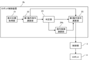
- FIG. 1 is a block diagram showing an example of a robot control device according to Embodiment 1;
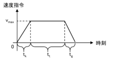
- FIG. 4 is a graph showing an example of an operation command in Embodiments 1 to 3;
- 4 is a graph showing the definition of settling time in Embodiments 1 to 3.
- FIG. 4 is a graph showing definitions of command parameters in Embodiments 1 to 3.
- FIG. It is an example of the resonance frequency of the robot 4 in Embodiments 1-3.
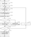
- 4 is a flow chart showing an example of the operation of the robot control device according to Embodiment 1;
- 4 is a flow chart showing an example of the operation of a second action command calculation section according to Embodiment 1.
- FIG. 9 is a flow chart showing another example of the operation of the second action command calculation section in Embodiment 1.
- FIG. FIG. 10 is a block diagram showing an example of a robot control device according to Embodiment 2;
- FIG. 9 is a flow chart showing an example of the operation of the robot control device according to Embodiment 2;
- FIG. 11 is a block diagram showing an example of a robot control device according to Embodiment 3;
- FIG. 12 is a graph showing an example of the relationship between the state quantity of the end effector and the settling time in the third embodiment;
- FIG. 14 is a flow chart showing an example of the operation of the robot control device according to Embodiment 3;
- 3 is a diagram showing a hardware configuration of a robot control device and a control unit according to Embodiments 1 to 3;
- FIG. 1 is a diagram showing an example of the configuration of a robot system 1 according to Embodiment 1. As shown in FIG. A robot system 1 includes a robot controller 2 , a controller 3 , and a robot 4 .
- the robot control device 2 calculates a second motion command based on the motion start position and motion end position in positioning the robot 4, and outputs the second motion command to the control unit 3 as a target command.
- Positioning of the robot 4 means positioning of the end effector 43 connected to the robot 4 .
- the robot control device 2 may be configured not within the robot system 1, but within a personal computer outside the robot system 1 or in the cloud. The robot control device 2 will be described later in detail with reference to FIG.
- the control unit 3 calculates a control signal for controlling the robot 4 according to the second motion command from the robot control device 2 and outputs the control signal to the actuator 41 of the robot 4 .
- the robot 4 includes an actuator 41 that drives the robot arm 42 and the end effector 43 , the robot arm 42 and the end effector 43 .
- the actuator 41 is, for example, a motor, and is connected to each joint of the robot arm 42 via a speed reducer.
- FIG. 2 is a block diagram showing an example of the robot control device 2 according to the first embodiment.
- the robot control device 2 includes a teaching position acquisition unit 21, a first motion command calculation unit 22, a determination unit 23, a command candidate calculation unit 24, and a second motion command calculation unit 25. Prepare.
- the teaching position acquisition unit 21 acquires the motion start position and the motion end position in positioning the robot 4 .
- the motion start position and motion end position are generated in advance by a means (not shown).
- the first motion command computation unit 22 computes the first motion command based on the motion start position and motion end position from the teaching position acquisition unit 21 .
- the operation command is any one of a position command, a speed command, an acceleration/deceleration command, etc. to the end effector 43 .
- 3 is a graph showing an example of an operation command according to Embodiment 1.
- FIG. FIG. 3 is a graph for a speed command to the end effector 43.
- FIG. The horizontal axis is the time, and the vertical axis is the speed command.
- the motion command consists of maximum speed V max , acceleration time t k , constant speed time t t and deceleration time t g .
- the operation command may be these variables themselves, a function of the graph shown in FIG. 3, or point sequence data sampled for each control cycle based on the graph of FIG. . If the operation command is the above variable or the function of the graph shown in FIG. Also, the operation command may be composed of variables other than the above variables.
- the first motion command calculator 22 calculates the first motion command by a known method based on the motion start position and the motion end position from the taught position acquisition part 21 .
- the first motion command calculator 22 computes the first motion command so as to maximize the angular acceleration while satisfying the constraints such as the angular acceleration of each joint axis of the robot 4 . That is, the first action command calculation unit 22 calculates the first action command so that the payout time is the shortest within the range that satisfies the constraint conditions.
- the first action command calculation section 22 outputs a first action command to the determination section 23 and the second action command calculation section 25 .
- the first motion command corresponds to a target command when the command candidate computation unit 24 and the second motion command computation unit 25, which will be described later, do not perform computation processing.
- the payout time refers to the period of the action command waveform from the action start position to the action end position. In the case of FIG. 3, the payout time is the sum of the acceleration time tk , the constant speed time tt and the deceleration time tg .
- the determination unit 23 calculates the first stationary time T1 when the robot 4 is operated according to the first motion command from the first motion command calculation unit 22.
- FIG. the determination unit 23 calculates the first settling time T1 by operating the robot 4 using dynamics simulation.
- the first settling time T1 is a settling time when the operation command is set as the first operation command in the settling time of the operation command, which will be described later with reference to FIG.
- the first payout time T 1, com is set to the first action command in the payout time of the action command shown in FIG . is the payout time of the hour.
- FIG. 4 is a graph showing the definition of settling time in the first embodiment.
- the horizontal axis is time
- the vertical axis is the state quantity of the end effector 43 .
- the time T indicates the time when the state quantity of the end effector 43 remains within the allowable range for the first time. Note that the definition of the settling time is not limited to this.
- the state quantity includes at least the position and orientation of the end effector 43 .
- the state quantity may also include the speed or acceleration of the end effector 43 .
- the command candidate calculation unit 24 calculates a motion command candidate that satisfies a predetermined condition with respect to the evaluation function based on the motion command and the motion command output time. do. If the difference ⁇ T 1 is less than the predetermined value ⁇ T chk , the command candidate calculation unit 24 does not perform any processing.
- the difference ⁇ T 1 is less than the predetermined value ⁇ T chk
- the amplitude of the residual vibration generated by the resonance of the robot 4 is smaller than the allowable range
- the first settling time T 1 is the first payout time T 1,com is almost the same as
- a method for setting the evaluation function and a method for calculating the operation command candidate by the command candidate calculation unit 24 will be described below.
- the command candidate computation unit 24 computes the gain at the characteristic frequency specified in advance based on the operation command, and sets an evaluation function including the gain and the weight of the gain.
- the evaluation function COST(p) is the following formula (1).
- N s is the set number of characteristic frequencies
- f i is the characteristic frequency
- K i is the gain weight at the characteristic frequency
- F(p, f i ) is the gain at the characteristic frequency f i
- p is the command parameter set.
- the command parameter set p is a collection of motion command candidates and command parameters that are subject to calculation of a second motion command to be described later. That is, calculating the motion command candidate and the second motion command is equivalent to computing the command parameter set p.
- FIG. 5(a) and 5(b) are graphs showing definitions of command parameters in the first embodiment.
- FIG. 5(a) shows an acceleration/deceleration command with respect to time.
- FIG. 5(b) shows a speed command with respect to time, which is obtained by integrating the acceleration/deceleration command of FIG. 5(a).
- the command parameters are acceleration increase time kt 1 , acceleration constant time kt 2 , acceleration decrease time kt 3 , deceleration increase time gt 1 , deceleration constant time gt 2 , deceleration decrease time gt 3 , maximum acceleration acc max . and maximum deceleration dec max .
- the constant speed time ct is set based on the command parameters so that the robot 4 reaches the motion end position. Therefore, the constant speed time ct is not included in the command parameters.
- the command parameter may be a parameter in the speed command of FIG. 5(b).
- the command parameters should include at least maximum speed, acceleration time and deceleration time.
- the maximum speed is v max in FIG. 5(b).
- the acceleration time is the sum of acceleration increase time kt- 1 , acceleration constant time kt- 2 , and acceleration decrease time kt -3 .
- the deceleration time is the sum of deceleration increase time gt- 1 , deceleration constant time gt- 2 , and deceleration decrease time gt- 3 .
- Gain F(p, f i ) in Equation (1) is calculated by substituting characteristic frequency f i for frequency f in gain F(p, f) in Equation (2) below.
- j is the imaginary unit
- ⁇ is the circular constant
- G(2 ⁇ j*f) is the Laplace transform of the time function g(t) into the frequency domain f.
- the time function g(t) expresses the motion command shown in FIG. 3 as a function.
- is the absolute value of the function G;
- the characteristic frequency f i in Equation (1) is, for example, the resonance frequency of the robot 4 calculated in advance.
- FIG. 6 shows an example of resonance frequencies of the robot 4 according to the first embodiment.
- FIG. 6 shows resonance frequencies calculated in advance every 0.1 [sec].
- the characteristic frequencies fi are 10 [Hz], 18 [Hz], 23 [Hz], 41.2 [Hz], 66 [Hz] and 132 [Hz].
- the command candidate calculation unit 24 may set the resonance frequency other than the time when the operation ends in each vibration mode as the characteristic frequency.
- the command candidate calculation unit 24 may set not only the resonance frequency of the robot 4 but also a frequency within a predetermined range around the resonance frequency as the characteristic frequency.
- the predetermined range may be a range of ⁇ 1 [Hz], for example.
- the characteristic frequencies of the primary vibration mode at the end of the operation in FIG. 6 are 9 [Hz], 10 [Hz] and 11 [Hz]. The same applies to other vibration modes.
- the command candidate calculation unit 24 may set, for example, 9 to 11 [Hz] as the characteristic frequency in increments of 0.5 [Hz].
- the gain weight K i in Equation (1) may be sloped so that it increases as the resonance frequency decreases, or may be uniform for each resonance frequency.
- the command candidate calculation unit 24 sets a frequency within a predetermined range before and after the resonance frequency as the characteristic frequency, for example, the gain weight K i at the resonance frequency is set to 1, and the gain weight K at frequencies 1 [Hz] before and after the resonance frequency. Let i be 0.8.
- the command candidate calculation unit 24 calculates command parameters included in the command parameter set (in the case of FIG. 5, acceleration increase time kt 1 , constant acceleration time kt 2 , acceleration decrease time kt 3 , deceleration increase time gt 1 , deceleration
- the initial values of the fixed time gt 2 , the deceleration decrease time gt 3 , the maximum acceleration acc max and the maximum deceleration dec max are set to M 1 (M 1 >1).
- the command candidate calculation unit 24 may determine the initial value of the command parameter set by determining the range of each command parameter and performing a grid search, or may randomly determine the initial value by Latin hypercube sampling or the like.
- the range of each command parameter is set such that the payout time does not exceed the first settling time T1 .
- the command candidate calculation unit 24 can set the initial values of the command parameter set in a wide range, and can globally calculate the motion command candidates. Note that the method of setting the initial values of the command parameter set is not particularly limited to these.
- the command candidate calculation unit 24 calculates the value of the evaluation function shown in Equation (1) for each of the initial values of the M1 sets of command parameter sets.
- the command candidate calculation unit 24 selects a command parameter set in which the value of the evaluation function is equal to or less than a predetermined value V1 and the payout time is equal to or less than a predetermined value V2 .
- the command candidate computing unit 24 computes motion commands corresponding to the command parameter sets of the selected M 2 sets (M 2 ⁇ 1, M 2 ⁇ M 1 ) as motion command candidates.
- Predetermined values V1 and V2 may be preset fixed values, or may be values such that a certain number of parameter sets remain after selection. It should be noted that the method by which the command candidate computation unit 24 computes the motion command candidates is not limited to the above method.
- the command candidate computing unit 24 computes the motion command candidate globally to some extent based on the evaluation function shown in formula (1). Therefore, the calculation time can be shortened compared to the case of calculating the settling time using the actual machine or the dynamics simulation and calculating the operation command candidate. In addition, since it is guaranteed that the motion command candidate has a high damping property, it becomes a motion command that is optimal to some extent. Therefore, even if the second motion command computing unit 25 computes the second motion command later using the dynamics simulation, the number of trials is small, so the computation time can be shortened as a whole.
- the second operation command calculation unit 25 calculates M 2 Based on the motion command candidates, a second motion command is calculated so that the static settling time is equal to or less than the first static settling time T1 when the robot 4 is operated, and the second motion command is output as a target command.
- the second action command calculation unit 25 sets the first action command as the second action command and outputs the second action command as the target command.
- the second action command calculation unit 25 may calculate the second action command using a black box search algorithm, or may calculate the second action command using an algorithm for obtaining a suboptimal solution without using the black box search algorithm. can be calculated. Details of each algorithm will be described in detail later with reference to FIGS. 8 and 9.
- FIG. Group reinforcement learning is an example of a black-box search algorithm. It should be noted that the method by which the second action command calculation unit 25 calculates the second action command is not limited to these.
- FIG. 7 is a flow chart showing an example of the operation of the robot control device 2 according to the first embodiment. That is, FIG. 7 is a flow chart showing an example of the robot control method according to the first embodiment.
- the teaching position acquisition unit 21 acquires the motion start position and motion end position of the robot 4 (step ST1).
- the first motion command computing section 22 computes the first motion command based on the motion start position and the motion end position (step ST2).
- the determination unit 23 calculates the first settling time T1 when the robot 4 is operated according to the first motion command using dynamics simulation, and determines the first settling time T1 , the first payout time T1 , and the first settling time T1 . com is calculated (step ST3 ).
- the determination unit 23 determines whether or not the difference ⁇ T 1 is less than a predetermined value ⁇ T chk (step ST4).
- step ST4 If the determination in step ST4 is "Yes”, the process proceeds to step ST5. If the determination in step ST4 is "No”, the process proceeds to step ST6.
- step ST4 If the determination in step ST4 is "Yes", the second action command calculation section 25 sets the first action command as the second action command (step ST5).
- step ST4 If the determination in step ST4 is "No", the command candidate calculation unit 24 calculates the resonance frequency of the robot 4 (step ST6).
- the command candidate calculation unit 24 sets the characteristic frequency based on the resonance frequency of the robot 4 (step ST7).
- the command candidate calculation unit 24 sets an evaluation function based on the motion command as shown in Equation (1) (step ST8).
- the command candidate computation unit 24 computes, as motion command candidates, motion commands that satisfy predetermined conditions for the evaluation function based on the motion command and the motion command output time (step ST9).
- the second motion command computing unit 25 computes a second motion command in which the settling time is equal to or shorter than the first settling time T1 based on the motion command candidate (step ST10).
- the processing of step ST10 will be described later in detail with reference to FIGS. 8 and 9. FIG.
- the second motion command calculator 25 outputs the second motion command as the target command (step ST11). After that, the control of the robot 4 is terminated by means not shown.
- FIG. 8 is a flow chart showing an example of the operation of the second operation command calculation section 25 according to Embodiment 1.
- FIG. 8 is a flowchart showing the details of the process of step ST10 in FIG. 7, and is a flowchart when the second action command calculation section 25 calculates the second action command using the black box search algorithm.
- the second action command calculation unit 25 when the second action command calculation unit 25 starts the calculation processing of the second action command, it sets the search count K (K ⁇ 1) to a predetermined value (step ST101).
- the second operation command calculation unit 25 initializes the counter k to 1 (step ST102).
- the number of command parameter sets to be added may be changed according to the loop variable k. For example, the number of sets to be added may be increased when the loop variable k is small, and the number of sets to be added may be decreased as the loop variable k increases. The number of sets to add may be a function of the loop variable k.
- the second motion command calculation unit 25 may add a slope such that many command parameter sets are added around the command parameter set that reduces the value of the evaluation function and the payout time.
- the second motion command calculation unit 25 calculates the static settling time when the robot 4 is operated by motion commands based on each of the M3 sets of command parameter sets added in step ST103, using a dynamics simulation (step ST104).
- the second operation command calculation unit 25 selects the minimum value T min of the settling time calculated in step ST104 (step ST105).
- the second operation command calculation unit 25 determines whether or not the minimum value Tmin of the settling time is less than the first settling time T1 (step ST106).
- step ST106 If the determination in step ST106 is "Yes”, the process proceeds to step ST107. If the determination in step ST106 is "No”, the process proceeds to step ST108.
- step ST106 When the determination in step ST106 is "Yes", the second operation command calculation section 25 stores in the memory the command parameter set corresponding to the minimum value Tmin of the settling time selected in step ST105 (step ST107). .
- step ST106 If the determination in step ST106 is "No", the command parameter set of the first motion command is stored in memory (step ST108).
- the second operation command calculation unit 25 determines whether or not the loop variable k is equal to the search count K (step ST109).
- step ST109 If the determination in step ST109 is "Yes”, the process proceeds to step ST110. If the determination in step ST109 is "No”, the process proceeds to step ST111.
- step ST109 determines whether the second action command calculation unit 25 is "Yes" or not. If the determination in step ST109 is "Yes”, the second action command calculation unit 25 sets the action command based on the command parameter set stored in the memory as the second action command (step ST110). After that, the second action command calculation unit 25 ends the calculation processing of the second action command.
- step ST109 When the determination in step ST109 is "No", the second operation command calculation unit 25 increases the loop variable k by 1 (step ST111). After that, the second operation command calculation section 25 performs the process of step ST103 again.
- FIG. 9 is a flow chart showing another example of the operation of the second operation command calculation section 25 according to the first embodiment. That is, FIG. 9 is a flowchart showing the details of the process of step ST10 in FIG. It is a flowchart in the case of computing.
- the payout time of the M2 sets of command parameter sets from the command candidate calculation unit 24 is the shortest.
- a command parameter set p_tmp is selected (step ST121).
- the second motion command calculation unit 25 uses dynamics simulation to calculate the settling time T tmp when the robot 4 is operated by the motion command based on the command parameter set p tmp (step ST122).
- the second operation command calculation unit 25 determines whether or not the settling time Ttmp is less than the first settling time T1 (step ST123).
- step ST123 If the determination in step ST123 is "Yes”, the process proceeds to step ST124. If the determination in step ST123 is "No”, the process proceeds to step ST125.
- step ST123 If the determination in step ST123 is "Yes", the second motion command calculator 25 stores the command parameter set p_tmp in the memory (step ST124).
- step ST123 When the determination in step ST123 is "No", the second motion command calculation unit 25 stores the command parameter set of the first motion command in memory (step ST125). Then, the process proceeds to step ST126.
- the second operation command calculation unit 25 selects the command parameter set p_slct for which the determination in step ST127 has not been performed, among the M2 sets of command parameter sets from the command candidate calculation unit 24 (step ST126).
- the second operation command calculation unit 25 determines whether or not the value of the evaluation function corresponding to the command parameter set p_slct is less than the value of the evaluation function corresponding to the command parameter set p_tmp (step ST127).
- step ST127 If the determination in step ST127 is "Yes”, the process proceeds to step ST128. If the determination in step ST127 is "No”, the process returns to step ST126.
- step ST127 If the determination in step ST127 is "Yes", the second motion command calculation unit 25 calculates the static set time T slct when the robot 4 is operated by the motion command based on the command parameter set p slct using dynamic simulation. Calculate (step ST128).
- the second operation command calculation unit 25 determines whether or not the settling time Tslct is less than the settling time Ttmp (step ST129).
- step ST129 If the determination in step ST129 is "Yes”, the process proceeds to step ST130. If the determination in step ST129 is "No”, the process proceeds to step ST131.
- step ST129 If the determination in step ST129 is "Yes", the second motion command calculator 25 stores the command parameter set p slct in the memory and writes the value of the command parameter set p slct to ptmp (step ST130).
- the second operation command calculation unit 25 determines whether evaluation of all of the M2 command parameter sets from the command candidate calculation unit 24 has been completed (step ST131). That is, the second operation command calculation unit 25 determines whether or not the determination in step ST127 has been performed for all of the M2 sets of command parameter sets.
- step ST131 If the determination in step ST131 is "Yes”, the process proceeds to step ST132. If the determination in step ST131 is "No”, the process returns to step ST126.
- step ST131 determines whether the second action command calculation section 25 is "Yes" or not. If the determination in step ST131 is "Yes”, the second action command calculation section 25 sets the action command based on the command parameter set stored in the memory as the second action command (step ST132). After that, the second action command calculation unit 25 ends the calculation processing of the second action command.
- the determination unit 23 determines the motion command candidate and the second motion based on the difference between the settling time and the dispensing time when the robot 4 is operated by the first motion command. Since it is determined whether or not to perform the operation of the instruction, the minimum necessary operation is sufficient. Even if it is determined that the calculation should be performed, the command candidate calculation unit 24 can search for the operation command candidate globally based on the evaluation function with a small calculation load. After that, the second motion command computing unit 25 computes the second motion command using dynamics simulation. , the second operation command can be calculated with a small number of trials. Therefore, even if the operation command before adjustment and the operation command after adjustment are far apart, the calculation time can be shortened.
- Embodiment 2 uses the sensor 5 to calculate the second motion command.
- FIG. 10 is a block diagram showing an example of the robot control device 2a according to the second embodiment.
- the robot control device 2a includes the sensor 5, the determination unit 23a instead of the determination unit 23, the command candidate calculation unit 24a instead of the command candidate calculation unit 24, and the second motion command. It differs from FIG.
- the components other than the determination unit 23a, the command candidate calculation unit 24a, and the second motion command calculation unit 25a are the same as those shown in FIG.
- the sensor 5 is a sensor that measures the position of the end effector 43 . Further, the sensor is not limited to this, and may be a sensor capable of calculating the state quantity of the end effector 43 by numerical calculation, such as an encoder, speed sensor, or acceleration sensor that measures the state quantity of the load directly or indirectly connected to the actuator 41 . may In this case, the sensor information from the sensor 5 is the state quantity such as the position, velocity or acceleration of the end effector 43 . Moreover, the sensor information may be the state quantity of the load connected to the actuator 41 .
- the determination unit 23a uses sensor information from the sensor 5 instead of the dynamics simulation. Specifically, the determination unit 23a causes the robot 4 to actually move according to the first motion command, and uses the sensor information from the sensor 5 to calculate the first settling time T1 . Other processing is the same as the processing performed by the determination unit 23 in the first embodiment.
- the command candidate calculation unit 24a changes the characteristic frequency f i of the evaluation function shown in Equation (1). Specifically, the command candidate calculation unit 24a obtains the vibration characteristics of the robot 4 by extracting information about the residual vibration after the completion of the command to the robot 4 from the sensor information. The command candidate calculation unit 24a identifies one or more peak frequencies included in the residual vibration by performing a fast Fourier transform on the extracted residual vibration component. The command candidate calculation unit 24a calculates the resonance frequency of the robot 4 based on the specified peak frequency, and sets the characteristic frequency fi . Other processing is the same as the processing performed by the command candidate calculation unit 24 in the first embodiment.
- the second motion command calculation unit 25a uses sensor information from the sensor 5 instead of the dynamics simulation. Specifically, the second motion command calculation unit 25a causes the robot 4 to actually move, and uses the sensor information from the sensor 5 to compute the second motion command. Other processing is the same as the processing performed by the second operation command calculation unit 25 in the first embodiment.
- the user may update the dynamics simulation based on the vibration characteristics of the robot 4 obtained from the sensor 5 .
- the determination unit 23a calculates the first settling time T1 using the updated dynamics simulation.
- the second motion command computing unit 25a computes the second motion command using the updated dynamics simulation.
- the update timing of the dynamics simulation is not particularly limited, and may be updated, for example, when the amount of change in the resonance frequency from the previous update reaches or exceeds a certain value. However, in the following description, it is assumed that the determination unit 23a and the second operation command calculation unit 25a use sensor information from the sensor 5. FIG.
- FIG. 11 is a flow chart showing an example of the operation of the robot control device 2a according to the second embodiment. That is, FIG. 11 is a flow chart showing an example of the robot control method according to the second embodiment.
- step ST12 is performed instead of step ST3
- step ST13 is performed instead of step ST6
- step ST14 is performed instead of step ST7
- step ST15 is performed instead of step ST8.
- step ST16 is performed instead of step ST10. Since steps other than steps ST12 to ST16 are the same as those shown in FIG. 7, description thereof is omitted.
- the determination unit 23a calculates, using the sensor 5 , the first settling time T1 when the robot 4 is operated according to the first motion command, and calculates the first settling time T1 and the first payout time T1 ,com. ⁇ T 1 is calculated (step ST12).
- step ST4 determines whether the determination in step ST4 is "No" or not.
- the command candidate calculation unit 24a calculates the resonance frequency of the robot 4 based on the sensor information from the sensor 5 (step ST13).
- the command candidate calculation unit 24a sets the characteristic frequency based on the resonance frequency of the robot 4 (step ST14).
- the command candidate calculation unit 24a sets an evaluation function based on the motion command as shown in Equation (1) (step ST15).
- the second motion command computing unit 25a computes a second motion command in which the settling time is equal to or shorter than the first settling time T1 based on the motion command candidates (step ST16).
- the second motion command calculator 25a computes the second motion command, it calculates the settling time using the sensor information from the sensor 5 instead of the dynamics simulation.
- the robot control device 2a can calculate the second motion command according to the actual motion of the robot 4 by using the sensor information from the sensor 5. Further, even if the vibration characteristics of the robot 4 change due to aging, etc., the second motion command can be calculated with high accuracy.
- Embodiment 3 the robot control device 2b sets the gain weight K i of the evaluation function shown in Equation (1) based on the relationship between the vibration of the robot 4 and the state quantity of the end effector 43 .
- FIG. 12 is a block diagram showing an example of the robot control device 2b according to the third embodiment.
- FIG. 12 differs from FIG. 2 in that a command candidate calculation section 24b is provided instead of the command candidate calculation section 24.
- the command candidate calculation unit 24b sets the gain weight K i of the evaluation function shown in Equation (1) based on the relationship between the vibration of the robot 4 and the state quantity of the end effector 43 . That is, the command candidate calculation unit 24 b sets the gain weight K i based on the influence of the vibration of the robot 4 on the state quantity of the end effector 43 .
- 13(a) and 13(b) are graphs showing an example of the relationship between the state quantity of the end effector 43 and the settling time in the third embodiment.
- FIG. 13A is a graph showing the horizontal position of the end effector 43, with the horizontal axis representing time and the vertical axis representing the state quantity.
- FIG. 13B is a graph showing the position of the end effector 43 in the height direction, with the horizontal axis representing time and the vertical axis representing the state quantity. In FIG. 13, a part of the graph within the payout period is omitted.
- the settling time of the lateral position of the end effector 43 is Ta .
- the settling time of the position of the end effector 43 in the height direction is Tb .
- the settling times T a and T b have a relationship of T a >T b , and the settling time as a whole is Ta . Furthermore, it is desirable to suppress lateral vibrations in order to shorten the overall settling time.
- Equation (3) As one method for estimating the influence of the vibration of the robot 4 on the state quantity of the end effector 43, there is a Jacobian matrix that represents the minute displacement of the position and orientation of the end effector 43 when each joint of the robot 4 is slightly displaced.
- the Jacobian matrix is given by Equation (3) below.
- the command candidate calculation unit 24b extracts a row corresponding to the lateral position of the end effector 43 in the Jacobian matrix, and selects a component with a large absolute value among the components of the extracted row. Since the column corresponding to the selected component corresponds to the joint of the robot 4, the command candidate calculation unit 24b identifies the vibration mode in which the corresponding joint has a large contribution rate, and increases the weight of the gain in that vibration mode. A method of setting the weight of the gain of the evaluation function will be described below.
- the command candidate calculation unit 24b performs vibration mode analysis of the robot 4 in order to set gain weights.
- the equation of motion of the robot 4 is the following formula (4).
- m is the inertia matrix of the robot arm 42
- h is the vector representing the centrifugal force and Coriolis force
- k is the torsional rigidity vector of the reduction gear connected to each joint axis
- x is the joint angle vector of the robot 4
- the dots are the first-order differential (one dot) and the second-order differential (two dots) of x
- x tgt is the command angle vector to each joint axis.
- ⁇ is a diagonal matrix.
- the frequency of the vibration mode of the robot 4 can be calculated from each component of the diagonal matrix ⁇ .
- the mode vector of the vibration mode is the eigenvector when one of the diagonal components of the diagonal matrix ⁇ is the eigenvalue.
- the command candidate calculation unit 24b determines the weight of the gain of the evaluation function according to the magnitude of the absolute value of the component corresponding to the joint selected in the Jacobian matrix among the components included in the eigenvector. For example, if the absolute value is a, the gain weight for the corresponding frequency is a. In this case, it is desirable to normalize each eigenvector.
- the vibration damping when it is small, it can be decomposed into each vibration mode.
- a general solution of vibration is obtained by analyzing the decomposed equation of motion for each vibration mode by a known technique. From this general solution, the damping ratio of the vibration is obtained. For example, when the damping ratio of a certain vibration mode is b, the command candidate calculator 24b sets the weight of the evaluation function for the corresponding frequency to b. In addition, since the natural frequency changes due to the damping characteristic, the command candidate calculation unit 24b changes the characteristic frequency f i to f i ' shown in Equation (7) below.
- FIG. 14 is a flow chart showing an example of the operation of the robot control device 2b according to the third embodiment. That is, FIG. 14 is a flow chart showing an example of the robot control method according to the third embodiment. 14 differs from FIG. 7 in that step ST17 is performed instead of step ST6, step ST18 is performed instead of step ST7, and step ST19 is performed instead of step ST8. . Since steps other than steps ST17 to ST19 are the same as those shown in FIG. 7, description thereof is omitted.
- the command candidate calculation unit 24b calculates the resonance frequency of the robot 4 based on the formula (7) as an example (step ST17).
- the command candidate calculation unit 24b sets the characteristic frequency based on the formula (7) as an example (step ST18).
- the command candidate calculation unit 24b sets an evaluation function based on the motion command as shown in Equation (1) (step ST19). At this time, the gain weight K i is set based on the mode vector of the vibration mode or the vibration damping ratio.
- the equation of motion of the robot 4 is used to set the gain weight K i based on the influence of the vibration of the robot 4 on the state quantity of the end effector 43 .
- the evaluation function it is possible to set the evaluation function with high accuracy, to preferentially improve the damping performance for frequencies directly linked to shortening of the settling time, and to calculate operation command candidates with shorter settling time.
- the processing circuitry comprises at least one processor and at least one memory.
- FIG. 15 is a diagram showing the hardware configuration of the robot control devices 2, 2a, 2b and the control section 3 in Embodiments 1-3.
- the robot controllers 2, 2a, 2b and controller 3 can be realized by the processor 6 and memory 7 shown in FIG. 15(a).
- the processor 6 is, for example, a CPU (Central Processing Unit, central processing unit, processing unit, arithmetic unit, microprocessor, microcomputer, processor, DSP (Digital Signal Processor)) or system LSI (Large Scale Integration).
- the memory 7 includes, for example, RAM (Random Access Memory), ROM (Read Only Memory), flash memory, EPROM (Erasable Programmable Read Only Memory), EEPROM (registered trademark) (Electrically Erasable Programmable Read - Non-volatile or Volatile semiconductor memory, HDD (Hard Disk Drive), magnetic disk, flexible disk, optical disk, compact disk, mini disk, DVD (Digital Versatile Disk), and the like.
- each part of the robot control devices 2, 2a, 2b and the control part 3 are realized by software (software, firmware, or software and firmware).
- Software or the like is written as a program and stored in the memory 7 .
- the processor 6 reads out and executes programs stored in the memory 7 to achieve the functions of each section. That is, it can be said that this program causes a computer to execute the procedures or methods of the robot controllers 2, 2a, 2b and the controller 3.
- the program executed by the processor 6 may be stored in a computer-readable storage medium in an installable or executable format and provided as a computer program product. Also, the program executed by the processor 6 may be provided to the robot controllers 2, 2a, 2b and the controller 3 via a network such as the Internet.
- the robot control devices 2, 2a, 2b and the control unit 3 may be realized by a dedicated processing circuit 8 shown in FIG. 15(b).
- the processing circuit 8 may be, for example, a single circuit, a composite circuit, a programmed processor, a parallel programmed processor, an ASIC (Application Specific Integrated Circuit), an FPGA (Field-Programmable Gate Array), or a combination thereof.
- the configuration in which the functions of the components of the robot control devices 2, 2a, 2b and the control unit 3 are realized by either software or hardware has been described above.
- the configuration is not limited to this, and may be a configuration in which a part of the components of the robot control devices 2, 2a, 2b and the control unit 3 are implemented by software or the like, and another part is implemented by dedicated hardware. good too.
- Embodiments 1 to 3 above are examples, and can be combined with another known technique. It is also possible to combine the first to third embodiments. Furthermore, it is also possible to omit or change part of the configuration without departing from the scope of the invention.
Landscapes
- Engineering & Computer Science (AREA)
- Human Computer Interaction (AREA)
- Manufacturing & Machinery (AREA)
- Physics & Mathematics (AREA)
- General Physics & Mathematics (AREA)
- Automation & Control Theory (AREA)
- Robotics (AREA)
- Mechanical Engineering (AREA)
- Manipulator (AREA)
- Numerical Control (AREA)
Priority Applications (2)
| Application Number | Priority Date | Filing Date | Title |
|---|---|---|---|
| JP2024502284A JP7726365B2 (ja) | 2022-02-22 | 2022-02-22 | ロボット制御装置およびロボット制御方法 |
| PCT/JP2022/007357 WO2023162031A1 (ja) | 2022-02-22 | 2022-02-22 | ロボット制御装置およびロボット制御方法 |
Applications Claiming Priority (1)
| Application Number | Priority Date | Filing Date | Title |
|---|---|---|---|
| PCT/JP2022/007357 WO2023162031A1 (ja) | 2022-02-22 | 2022-02-22 | ロボット制御装置およびロボット制御方法 |
Publications (1)
| Publication Number | Publication Date |
|---|---|
| WO2023162031A1 true WO2023162031A1 (ja) | 2023-08-31 |
Family
ID=87765174
Family Applications (1)
| Application Number | Title | Priority Date | Filing Date |
|---|---|---|---|
| PCT/JP2022/007357 Ceased WO2023162031A1 (ja) | 2022-02-22 | 2022-02-22 | ロボット制御装置およびロボット制御方法 |
Country Status (2)
| Country | Link |
|---|---|
| JP (1) | JP7726365B2 (https=) |
| WO (1) | WO2023162031A1 (https=) |
Citations (6)
| Publication number | Priority date | Publication date | Assignee | Title |
|---|---|---|---|---|
| JPH05301196A (ja) * | 1992-04-28 | 1993-11-16 | Canon Inc | ロボット制御系パラメータ調整装置 |
| JPH06250723A (ja) * | 1993-02-25 | 1994-09-09 | Komatsu Ltd | ロボットの振動低減装置 |
| WO2000042479A1 (de) * | 1999-01-14 | 2000-07-20 | Siemens Aktiengesellschaft | Steuerungsverfahren sowie numerische steuerung zur schwingungsarmen beschleunigungsführung eines bewegbaren maschinenelementes |
| JP2011088225A (ja) * | 2009-10-20 | 2011-05-06 | Yaskawa Electric Corp | インピーダンス制御パラメータの調整装置および調整方法 |
| JP2019111604A (ja) * | 2017-12-22 | 2019-07-11 | セイコーエプソン株式会社 | 制御装置、ロボット、およびロボットシステム |
| WO2022009333A1 (ja) * | 2020-07-08 | 2022-01-13 | 三菱電機株式会社 | ロボット制御装置、ロボット制御方法、およびロボット制御プログラム |
-
2022
- 2022-02-22 JP JP2024502284A patent/JP7726365B2/ja active Active
- 2022-02-22 WO PCT/JP2022/007357 patent/WO2023162031A1/ja not_active Ceased
Patent Citations (6)
| Publication number | Priority date | Publication date | Assignee | Title |
|---|---|---|---|---|
| JPH05301196A (ja) * | 1992-04-28 | 1993-11-16 | Canon Inc | ロボット制御系パラメータ調整装置 |
| JPH06250723A (ja) * | 1993-02-25 | 1994-09-09 | Komatsu Ltd | ロボットの振動低減装置 |
| WO2000042479A1 (de) * | 1999-01-14 | 2000-07-20 | Siemens Aktiengesellschaft | Steuerungsverfahren sowie numerische steuerung zur schwingungsarmen beschleunigungsführung eines bewegbaren maschinenelementes |
| JP2011088225A (ja) * | 2009-10-20 | 2011-05-06 | Yaskawa Electric Corp | インピーダンス制御パラメータの調整装置および調整方法 |
| JP2019111604A (ja) * | 2017-12-22 | 2019-07-11 | セイコーエプソン株式会社 | 制御装置、ロボット、およびロボットシステム |
| WO2022009333A1 (ja) * | 2020-07-08 | 2022-01-13 | 三菱電機株式会社 | ロボット制御装置、ロボット制御方法、およびロボット制御プログラム |
Also Published As
| Publication number | Publication date |
|---|---|
| JPWO2023162031A1 (https=) | 2023-08-31 |
| JP7726365B2 (ja) | 2025-08-20 |
Similar Documents
| Publication | Publication Date | Title |
|---|---|---|
| JP6494897B1 (ja) | 数値制御装置 | |
| JP7095834B2 (ja) | 制御パラメータ計算方法、制御パラメータ計算プログラム、及び制御パラメータ計算装置 | |
| EP3023208B1 (en) | Control device for motor drive device, control device for multi-axial motor, and control method for motor drive device | |
| JP2009537926A (ja) | 閉ループ制御のチューニングの自動化 | |
| CN103429986B (zh) | 惯性导航划桨算法 | |
| CN113954078B (zh) | 力控关节控制方法、装置、机器人和可读存储介质 | |
| US12117785B2 (en) | Control device, model creation method, and control program | |
| US12547128B2 (en) | Adjustment system, adjustment method, and adjustment program | |
| JP6545390B2 (ja) | パラレルリンク機構の制御装置 | |
| JP7332005B1 (ja) | 制御装置及び制御方法 | |
| WO2023162031A1 (ja) | ロボット制御装置およびロボット制御方法 | |
| CN101943889B (zh) | 使电气传动系统调节器自动启动和/或运行的方法及装置 | |
| Yang et al. | Frequency domain control of flexible beams with piezoelectric actuator | |
| EP3923091B1 (en) | Control device and control program | |
| JP7331779B2 (ja) | 機械制御システム、波形生成装置、波形生成方法、および波形生成プログラム | |
| CN114268246B (zh) | 电机控制方法、装置、系统及计算机可读存储介质 | |
| JP7584714B1 (ja) | 振動抑制装置、ロボットシステム、および振動抑制方法 | |
| KR102947931B1 (ko) | 모터 제어 장치 | |
| JP7059957B2 (ja) | 制御装置および制御プログラム | |
| JPWO2023162031A5 (https=) | ||
| US20080000292A1 (en) | System for Nano Position Sensing in Scanning Probe Microscopes using an Estimator | |
| JP2020129293A (ja) | 制御装置および制御プログラム | |
| JP2004094336A (ja) | サーボ系の調整方法およびその制御装置 | |
| CN121515175A (zh) | 基于动力学模型的机器人关节力矩生成方法、装置及终端 | |
| JPWO2025163748A5 (https=) |
Legal Events
| Date | Code | Title | Description |
|---|---|---|---|
| 121 | Ep: the epo has been informed by wipo that ep was designated in this application |
Ref document number: 22928562 Country of ref document: EP Kind code of ref document: A1 |
|
| WWE | Wipo information: entry into national phase |
Ref document number: 2024502284 Country of ref document: JP |
|
| NENP | Non-entry into the national phase |
Ref country code: DE |
|
| 122 | Ep: pct application non-entry in european phase |
Ref document number: 22928562 Country of ref document: EP Kind code of ref document: A1 |