WO2023157501A1 - 面状照明装置 - Google Patents
面状照明装置 Download PDFInfo
- Publication number
- WO2023157501A1 WO2023157501A1 PCT/JP2022/048623 JP2022048623W WO2023157501A1 WO 2023157501 A1 WO2023157501 A1 WO 2023157501A1 JP 2022048623 W JP2022048623 W JP 2022048623W WO 2023157501 A1 WO2023157501 A1 WO 2023157501A1
- Authority
- WO
- WIPO (PCT)
- Prior art keywords
- light
- lens
- field lens
- liquid crystal
- crystal panel
- Prior art date
- Legal status (The legal status is an assumption and is not a legal conclusion. Google has not performed a legal analysis and makes no representation as to the accuracy of the status listed.)
- Ceased
Links
Images


Classifications
-
- G—PHYSICS
- G02—OPTICS
- G02F—OPTICAL DEVICES OR ARRANGEMENTS FOR THE CONTROL OF LIGHT BY MODIFICATION OF THE OPTICAL PROPERTIES OF THE MEDIA OF THE ELEMENTS INVOLVED THEREIN; NON-LINEAR OPTICS; FREQUENCY-CHANGING OF LIGHT; OPTICAL LOGIC ELEMENTS; OPTICAL ANALOGUE/DIGITAL CONVERTERS
- G02F1/00—Devices or arrangements for the control of the intensity, colour, phase, polarisation or direction of light arriving from an independent light source, e.g. switching, gating or modulating; Non-linear optics
- G02F1/01—Devices or arrangements for the control of the intensity, colour, phase, polarisation or direction of light arriving from an independent light source, e.g. switching, gating or modulating; Non-linear optics for the control of the intensity, phase, polarisation or colour
- G02F1/13—Devices or arrangements for the control of the intensity, colour, phase, polarisation or direction of light arriving from an independent light source, e.g. switching, gating or modulating; Non-linear optics for the control of the intensity, phase, polarisation or colour based on liquid crystals, e.g. single liquid crystal display cells
- G02F1/133—Constructional arrangements; Operation of liquid crystal cells; Circuit arrangements
- G02F1/1333—Constructional arrangements; Manufacturing methods
- G02F1/1335—Structural association of cells with optical devices, e.g. polarisers or reflectors
- G02F1/1336—Illuminating devices
- G02F1/133602—Direct backlight
- G02F1/133606—Direct backlight including a specially adapted diffusing, scattering or light controlling members
- G02F1/133607—Direct backlight including a specially adapted diffusing, scattering or light controlling members the light controlling member including light directing or refracting elements, e.g. prisms or lenses
-
- F—MECHANICAL ENGINEERING; LIGHTING; HEATING; WEAPONS; BLASTING
- F21—LIGHTING
- F21S—NON-PORTABLE LIGHTING DEVICES; SYSTEMS THEREOF; VEHICLE LIGHTING DEVICES SPECIALLY ADAPTED FOR VEHICLE EXTERIORS
- F21S2/00—Systems of lighting devices, not provided for in main groups F21S4/00 - F21S10/00 or F21S19/00, e.g. of modular construction
-
- F—MECHANICAL ENGINEERING; LIGHTING; HEATING; WEAPONS; BLASTING
- F21—LIGHTING
- F21V—FUNCTIONAL FEATURES OR DETAILS OF LIGHTING DEVICES OR SYSTEMS THEREOF; STRUCTURAL COMBINATIONS OF LIGHTING DEVICES WITH OTHER ARTICLES, NOT OTHERWISE PROVIDED FOR
- F21V13/00—Producing particular characteristics or distribution of the light emitted by means of a combination of elements specified in two or more of main groups F21V1/00 - F21V11/00
- F21V13/02—Combinations of only two kinds of elements
- F21V13/04—Combinations of only two kinds of elements the elements being reflectors and refractors
-
- F—MECHANICAL ENGINEERING; LIGHTING; HEATING; WEAPONS; BLASTING
- F21—LIGHTING
- F21V—FUNCTIONAL FEATURES OR DETAILS OF LIGHTING DEVICES OR SYSTEMS THEREOF; STRUCTURAL COMBINATIONS OF LIGHTING DEVICES WITH OTHER ARTICLES, NOT OTHERWISE PROVIDED FOR
- F21V5/00—Refractors for light sources
- F21V5/02—Refractors for light sources of prismatic shape
-
- F—MECHANICAL ENGINEERING; LIGHTING; HEATING; WEAPONS; BLASTING
- F21—LIGHTING
- F21V—FUNCTIONAL FEATURES OR DETAILS OF LIGHTING DEVICES OR SYSTEMS THEREOF; STRUCTURAL COMBINATIONS OF LIGHTING DEVICES WITH OTHER ARTICLES, NOT OTHERWISE PROVIDED FOR
- F21V5/00—Refractors for light sources
- F21V5/04—Refractors for light sources of lens shape
-
- F—MECHANICAL ENGINEERING; LIGHTING; HEATING; WEAPONS; BLASTING
- F21—LIGHTING
- F21V—FUNCTIONAL FEATURES OR DETAILS OF LIGHTING DEVICES OR SYSTEMS THEREOF; STRUCTURAL COMBINATIONS OF LIGHTING DEVICES WITH OTHER ARTICLES, NOT OTHERWISE PROVIDED FOR
- F21V7/00—Reflectors for light sources
- F21V7/04—Optical design
- F21V7/09—Optical design with a combination of different curvatures
-
- G—PHYSICS
- G02—OPTICS
- G02B—OPTICAL ELEMENTS, SYSTEMS OR APPARATUS
- G02B19/00—Condensers, e.g. light collectors or similar non-imaging optics
- G02B19/0004—Condensers, e.g. light collectors or similar non-imaging optics characterised by the optical means employed
- G02B19/0009—Condensers, e.g. light collectors or similar non-imaging optics characterised by the optical means employed having refractive surfaces only
- G02B19/0014—Condensers, e.g. light collectors or similar non-imaging optics characterised by the optical means employed having refractive surfaces only at least one surface having optical power
-
- G—PHYSICS
- G02—OPTICS
- G02B—OPTICAL ELEMENTS, SYSTEMS OR APPARATUS
- G02B19/00—Condensers, e.g. light collectors or similar non-imaging optics
- G02B19/0033—Condensers, e.g. light collectors or similar non-imaging optics characterised by the use
- G02B19/0047—Condensers, e.g. light collectors or similar non-imaging optics characterised by the use for use with a light source
- G02B19/0061—Condensers, e.g. light collectors or similar non-imaging optics characterised by the use for use with a light source the light source comprising a LED
- G02B19/0066—Condensers, e.g. light collectors or similar non-imaging optics characterised by the use for use with a light source the light source comprising a LED in the form of an LED array
-
- G—PHYSICS
- G02—OPTICS
- G02B—OPTICAL ELEMENTS, SYSTEMS OR APPARATUS
- G02B27/00—Optical systems or apparatus not provided for by any of the groups G02B1/00 - G02B26/00, G02B30/00
- G02B27/01—Head-up displays
-
- G—PHYSICS
- G02—OPTICS
- G02B—OPTICAL ELEMENTS, SYSTEMS OR APPARATUS
- G02B27/00—Optical systems or apparatus not provided for by any of the groups G02B1/00 - G02B26/00, G02B30/00
- G02B27/01—Head-up displays
- G02B27/0101—Head-up displays characterised by optical features
-
- G—PHYSICS
- G02—OPTICS
- G02B—OPTICAL ELEMENTS, SYSTEMS OR APPARATUS
- G02B3/00—Simple or compound lenses
- G02B3/0006—Arrays
- G02B3/0037—Arrays characterized by the distribution or form of lenses
- G02B3/005—Arrays characterized by the distribution or form of lenses arranged along a single direction only, e.g. lenticular sheets
-
- G—PHYSICS
- G02—OPTICS
- G02B—OPTICAL ELEMENTS, SYSTEMS OR APPARATUS
- G02B3/00—Simple or compound lenses
- G02B3/02—Simple or compound lenses with non-spherical faces
- G02B3/08—Simple or compound lenses with non-spherical faces with discontinuous faces, e.g. Fresnel lens
-
- G—PHYSICS
- G02—OPTICS
- G02F—OPTICAL DEVICES OR ARRANGEMENTS FOR THE CONTROL OF LIGHT BY MODIFICATION OF THE OPTICAL PROPERTIES OF THE MEDIA OF THE ELEMENTS INVOLVED THEREIN; NON-LINEAR OPTICS; FREQUENCY-CHANGING OF LIGHT; OPTICAL LOGIC ELEMENTS; OPTICAL ANALOGUE/DIGITAL CONVERTERS
- G02F1/00—Devices or arrangements for the control of the intensity, colour, phase, polarisation or direction of light arriving from an independent light source, e.g. switching, gating or modulating; Non-linear optics
- G02F1/01—Devices or arrangements for the control of the intensity, colour, phase, polarisation or direction of light arriving from an independent light source, e.g. switching, gating or modulating; Non-linear optics for the control of the intensity, phase, polarisation or colour
- G02F1/13—Devices or arrangements for the control of the intensity, colour, phase, polarisation or direction of light arriving from an independent light source, e.g. switching, gating or modulating; Non-linear optics for the control of the intensity, phase, polarisation or colour based on liquid crystals, e.g. single liquid crystal display cells
- G02F1/133—Constructional arrangements; Operation of liquid crystal cells; Circuit arrangements
- G02F1/1333—Constructional arrangements; Manufacturing methods
- G02F1/1335—Structural association of cells with optical devices, e.g. polarisers or reflectors
- G02F1/1336—Illuminating devices
- G02F1/133601—Illuminating devices for spatial active dimming
-
- G—PHYSICS
- G02—OPTICS
- G02F—OPTICAL DEVICES OR ARRANGEMENTS FOR THE CONTROL OF LIGHT BY MODIFICATION OF THE OPTICAL PROPERTIES OF THE MEDIA OF THE ELEMENTS INVOLVED THEREIN; NON-LINEAR OPTICS; FREQUENCY-CHANGING OF LIGHT; OPTICAL LOGIC ELEMENTS; OPTICAL ANALOGUE/DIGITAL CONVERTERS
- G02F1/00—Devices or arrangements for the control of the intensity, colour, phase, polarisation or direction of light arriving from an independent light source, e.g. switching, gating or modulating; Non-linear optics
- G02F1/01—Devices or arrangements for the control of the intensity, colour, phase, polarisation or direction of light arriving from an independent light source, e.g. switching, gating or modulating; Non-linear optics for the control of the intensity, phase, polarisation or colour
- G02F1/13—Devices or arrangements for the control of the intensity, colour, phase, polarisation or direction of light arriving from an independent light source, e.g. switching, gating or modulating; Non-linear optics for the control of the intensity, phase, polarisation or colour based on liquid crystals, e.g. single liquid crystal display cells
- G02F1/133—Constructional arrangements; Operation of liquid crystal cells; Circuit arrangements
- G02F1/1333—Constructional arrangements; Manufacturing methods
- G02F1/1335—Structural association of cells with optical devices, e.g. polarisers or reflectors
- G02F1/1336—Illuminating devices
- G02F1/133602—Direct backlight
- G02F1/133605—Direct backlight including specially adapted reflectors
-
- F—MECHANICAL ENGINEERING; LIGHTING; HEATING; WEAPONS; BLASTING
- F21—LIGHTING
- F21Y—INDEXING SCHEME ASSOCIATED WITH SUBCLASSES F21K, F21L, F21S and F21V, RELATING TO THE FORM OR THE KIND OF THE LIGHT SOURCES OR OF THE COLOUR OF THE LIGHT EMITTED
- F21Y2115/00—Light-generating elements of semiconductor light sources
- F21Y2115/10—Light-emitting diodes [LED]
-
- G—PHYSICS
- G02—OPTICS
- G02B—OPTICAL ELEMENTS, SYSTEMS OR APPARATUS
- G02B27/00—Optical systems or apparatus not provided for by any of the groups G02B1/00 - G02B26/00, G02B30/00
- G02B27/01—Head-up displays
- G02B27/0101—Head-up displays characterised by optical features
- G02B2027/0118—Head-up displays characterised by optical features comprising devices for improving the contrast of the display / brillance control visibility
-
- G—PHYSICS
- G02—OPTICS
- G02F—OPTICAL DEVICES OR ARRANGEMENTS FOR THE CONTROL OF LIGHT BY MODIFICATION OF THE OPTICAL PROPERTIES OF THE MEDIA OF THE ELEMENTS INVOLVED THEREIN; NON-LINEAR OPTICS; FREQUENCY-CHANGING OF LIGHT; OPTICAL LOGIC ELEMENTS; OPTICAL ANALOGUE/DIGITAL CONVERTERS
- G02F1/00—Devices or arrangements for the control of the intensity, colour, phase, polarisation or direction of light arriving from an independent light source, e.g. switching, gating or modulating; Non-linear optics
- G02F1/01—Devices or arrangements for the control of the intensity, colour, phase, polarisation or direction of light arriving from an independent light source, e.g. switching, gating or modulating; Non-linear optics for the control of the intensity, phase, polarisation or colour
- G02F1/13—Devices or arrangements for the control of the intensity, colour, phase, polarisation or direction of light arriving from an independent light source, e.g. switching, gating or modulating; Non-linear optics for the control of the intensity, phase, polarisation or colour based on liquid crystals, e.g. single liquid crystal display cells
- G02F1/133—Constructional arrangements; Operation of liquid crystal cells; Circuit arrangements
- G02F1/1333—Constructional arrangements; Manufacturing methods
- G02F1/1335—Structural association of cells with optical devices, e.g. polarisers or reflectors
- G02F1/1336—Illuminating devices
- G02F1/133602—Direct backlight
- G02F1/133603—Direct backlight with LEDs
Definitions
- the present invention relates to a planar lighting device.
- a head-up display (HUD) that uses an automobile window shield or the like is known (see, for example, Patent Documents 1 and 2). Since the light source unit of such a head-up display is installed near the window shield exposed to sunlight, countermeasures against heat and stray light due to sunlight are often taken.
- a liquid crystal panel is arranged on the emission surface side, and one or more mirrors are provided in the subsequent stage, and projection is performed on the window shield. Therefore, the heat of sunlight entering through the window shield and mirrors from the outside of the automobile deteriorates the liquid crystal panel and the planar lighting device, and the stray light adversely affects the display.
- the liquid crystal panel is often arranged so that it is tilted in the same direction as the first-stage mirror with respect to the main optical axis from the planar illumination device to the first-stage mirror.
- the liquid crystal panel By arranging the liquid crystal panel in a tilted state, the sunlight entering in the opposite direction to the projection is more likely to be reflected on the surface of the liquid crystal panel, and the sunlight enters the inside of the liquid crystal panel and the planar lighting device. Blocking intrusion reduces problems with heat and stray light.
- the tilt of the liquid crystal panel does not pose a particular problem for the planar lighting device that does not support local dimming, but in the planar lighting device that supports local dimming, it reduces the contrast and luminance uniformity. cause new problems.
- Local dimming is a direct-type planar lighting device in which light sources such as LEDs (Light Emitting Diodes) are arranged two-dimensionally. By controlling the amount of light emitted by each light source, the contrast ratio of different areas within the same screen can be significantly increased. It is a technology that enhances
- the light distribution characteristic is often given to the outside so that the visibility of the peripheral edge does not deteriorate even if the light is converged by the concave mirror used as a part of the rear stage mirror. . Therefore, by arranging the liquid crystal panel at an angle with respect to the main optical axis of the planar illumination device, there is a difference in optical distance between the field lens and the liquid crystal panel, which gives light distribution characteristics that are open to the outside. occur. Due to this difference in optical distance, light that protrudes from the local dimming zone area (dimming zone) is generated, resulting in deterioration of contrast and brightness uniformity.
- the present invention has been made in view of the above, and an object of the present invention is to provide a planar illumination device capable of improving contrast and brightness uniformity.
- a planar illumination device includes a plurality of light sources, a condenser lens, and a field lens.
- the plurality of light sources are two-dimensionally arranged on the substrate, and light emission is individually controlled.
- the condenser lens is arranged parallel to the substrate on the output side of the light source, and converges the light emitted from the light source into substantially parallel light.
- the field lens is arranged on the output side of the condenser lens, is arranged to be inclined in at least one direction perpendicular to the plane parallel to the substrate, spreads the light incident from the condenser lens outward, and is externally mounted. A uniform optical distance is ensured between the liquid crystal panel to be connected.
- a planar lighting device can improve contrast and luminance uniformity.
- FIG. 1 is a diagram showing a configuration example of a head-up display system.
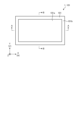
- FIG. 2 is a plan view of a planar illumination device equipped with a liquid crystal panel.
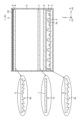
- FIG. 3 is a cross-sectional view taken along line AA of FIG.
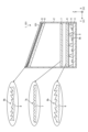
- FIG. 4 is a cross-sectional view along BB in FIG.
- FIG. 5 is a diagram showing an example of light distribution in the horizontal direction (X-axis direction).
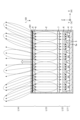
- FIG. 6 is a diagram showing an example of light distribution in the vertical direction (Y-axis direction).
- FIG. 7 is a diagram showing a configuration example of a planar illumination device and a liquid crystal panel of Comparative Example #1, and an example of light distribution in the vertical direction (Y-axis direction).
- FIG. 8 is a diagram showing a configuration example of a planar illumination device and a liquid crystal panel of Comparative Example #2 and an example of light distribution in the vertical direction (Y-axis direction).
- a planar illumination device will be described below with reference to the drawings.
- this invention is not limited by this embodiment.
- the dimensional relationship of each element in the drawings, the ratio of each element, and the like may differ from reality. Even between the drawings, there are cases where portions with different dimensional relationships and ratios are included.
- the contents described in one embodiment and modification are in principle similarly applied to other embodiments and modifications.
- FIG. 1 is a diagram showing a configuration example of a head-up display system 100.
- FIG. 1 in the case of a head-up display system 100 mounted on an automobile, the traveling direction of the automobile is the left direction (positive direction of the Y-axis) in the drawing.
- the liquid crystal panel 101 is arranged so as to be inclined in the same direction as the mirror 102 with respect to the main optical axis (L1) extending from the planar illumination device 1 to the mirror 102 at the first stage.
- the liquid crystal panel 101 in a tilted state, when the sunlight irradiated from above the window shield 104 enters the liquid crystal panel 101 through the window shield 104, the concave mirror 103 and the mirror 102, the sunlight is prevented from entering the liquid crystal. It becomes easy to reflect on the surface of the panel 101 . This prevents sunlight from entering the interior of the liquid crystal panel 101 and the planar illumination device 1, thereby reducing problems caused by heat and stray light.
- the components and arrangement of the head-up display system 100 in FIG. 1 are examples, and the optical axis of the planar lighting device 1 may be set in the horizontal direction, or the configuration of the mirrors including the number of mirrors may be different. There is also
- FIG. 2 is a plan view of the planar illumination device 1 to which the liquid crystal panel 101 is attached.
- the bottom surface of the planar illumination device 1 is in the XY plane, and the thickness direction of the planar illumination device 1 is the Z direction.
- the X-axis direction corresponds to the horizontal direction (H)
- the Y-axis direction corresponds to the vertical direction (V).
- the horizontal direction and the vertical direction in the state of use that are reflected by the window shield 104 and visible to the user may be simply referred to as the “horizontal direction” and the “vertical direction”.
- the planar illumination device 1 has a substantially rectangular planar shape, and a liquid crystal panel 101 is arranged on the output surface.
- the periphery of the liquid crystal panel 101 is a frame portion 101b, and the inside thereof is a display area 101a.
- FIG. 3 is a cross-sectional view along line AA in FIG.
- FIG. 4 is a cross-sectional view along BB in FIG. 3 and 4
- the planar lighting device 1 has a box-like frame 2 with a bottom.
- a substrate 3 made of aluminum or the like having excellent heat dissipation properties is arranged.
- a plurality of light sources 4, such as LEDs (Light Emitting Diodes), are arranged two-dimensionally on the substrate 3 in a grid-like manner, while being appropriately insulated.
- the individual light sources 4 are individually driven and their light emission is individually controlled to correspond to so-called local dimming.
- a reflector 5 having four reflecting surfaces 5a and 5b surrounding each of the plurality of light sources 4 is arranged on the output side of the substrate 3 where the light sources 4 are arranged.
- the reflector 5 is made of resin or the like.
- the reflector 5 may be arranged in a floating state from the light source 4 in some cases. Reflector 5 may be omitted.
- a condenser lens 6 for condensing light is arranged parallel to the substrate 3 on the output side of the reflector 5 .
- the condenser lens 6 has linear grooves extending in one direction (the depth direction (Y-axis direction) in the figure) forming the uneven surface of the lens, as shown in FIG.
- a Fresnel lens 6a is formed.
- grooves forming the concave-convex surface of the lens are formed on the surface of the condenser lens 6 on the output side on the upper side in the drawing in a direction orthogonal to one direction of the lower surface (left and right in the drawing).
- a linear Fresnel lens 6b extending in the direction (X-axis direction) is formed.
- Each of the linear Fresnel lenses 6a and 6b has a prism structure using a cylindrical convex lens as a Fresnel lens. At the segment boundaries between segments, the prism angles are reversed. It is easier to manufacture than a ring-shaped Fresnel lens.
- a field lens 7 for widening the light distribution is arranged on the output side of the condenser lens 6 .
- On the lower surface of the field lens 7 in the drawing as shown in FIG. 3, there is a lenticular lens 7a in which the grooves constituting the concave-convex surface of the lens extend in one direction (depth direction in the drawing (Y-axis direction)). formed.
- a lenticular lens 7a in which the grooves constituting the concave-convex surface of the lens extend in one direction (depth direction in the drawing (Y-axis direction)). formed.
- FIG. 4 on the upper surface of the field lens 7 in the drawing, grooves forming the concave-convex surface of the lens are formed in a direction orthogonal to one direction of the lower surface (horizontal direction in the drawing (the X-axis direction in the drawing). )) is formed with a lenticular lens 7b.
- the lenticular lenses 7a and 7b have a prism shape with a semicylindrical cross section, and spread incident light.
- the diffusion plate spreads the light in all directions, causing a decrease in efficiency, but the lenticular lenses 7a and 7b can adjust the spread of the light distribution within a necessary range according to the cross-sectional shape, resulting in a decrease in light efficiency. This is advantageous because it does not invite
- a field lens 8 is arranged on the output side of the field lens 7 to spread the light distribution outward.
- the reason for widening the light distribution is to provide a light distribution characteristic that is open to the outside so that the visibility of the periphery does not deteriorate even if the light is converged by the concave mirror 103 included in the head-up display system 100 (FIG. 1). .
- the field lens 8 is not tilted in the X-axis direction (horizontal direction), and is arranged parallel to the substrate 3, the condenser lens 6 and the field lens 7, as shown in FIG. 4, the field lens 8 is arranged to be inclined with respect to the substrate 3, the condenser lens 6 and the field lens 7 in the Y-axis direction (vertical direction).
- FIG. 3 On the lower surface of the field lens 8 in the figure, as shown in FIG. 3, there is a linear prism 8a in which the grooves constituting the concave-convex surface of the lens extend in one direction (depth direction in the figure (Y-axis direction)). formed.
- FIG. 4 on the upper surface of the field lens 8 in the figure, the grooves forming the concave-convex surface of the lens are formed in a direction orthogonal to one direction of the lower surface (horizontal direction in the figure (the X-axis direction in the figure). )) is formed with a linear prism 8b.
- the linear prisms 8a and 8b allow the light passing through the central portion of the full width to travel straight in the Z-axis direction, and direct the optical axis of each location outward toward the outside. Note that the light passing through the central portion of the full width may also be inclined from the Z-axis direction.
- An optical sheet 9 matching the characteristics of the liquid crystal panel 101 to be mounted is arranged parallel to the field lens 8 on the output side of the field lens 8 .
- a polarizing reflection sheet or a diffusion sheet is used as the optical sheet 9 .
- the thickness of the optical sheet 9 is, for example, about 0.4 mm.
- a liquid crystal panel 101 for forming an image to be projected is arranged parallel to the optical sheet 9 and the field lens 8 on the output side of the optical sheet 9 . What is important here is to secure a uniform optical distance between the field lens 8 and the liquid crystal panel 101 . It is also important that both the field lens 8 and the liquid crystal panel 101 are close to each other. The smaller the distance between the field lens 8 and the liquid crystal panel 101, the less the light spread to the adjacent dimming zone, the less light loss, and the better the contrast.
- the distance between the field lens 8 and the liquid crystal panel 101 may be zero (proximity with substantially no gap), but the optical characteristics, the thickness of the optical sheet 9 when provided, and the positioning mechanism of each optical member Considering the thickness of the film, the thickness is preferably 3 mm or less, more preferably 2 mm or less. As long as the distance between the field lens 8 and the liquid crystal panel 101 is 3 mm or less, the field lens 8 and the liquid crystal panel 101 do not necessarily have to be arranged in parallel.
- FIG. 5 is a diagram showing an example of light distribution in the horizontal direction (X-axis direction).
- the light L11 emitted from the light source 4 is converged into substantially parallel light by the condenser lens 6 (linear Fresnel lens 6a on the lower surface) to become light L12.
- the light L12 is expanded in light distribution by the field lens 7 (the lenticular lens 7a on the lower surface) while keeping the optical axis as it is, and becomes light L13.
- the optical axis of the light L13 is tilted outward at each location by the field lens 8 (the linear prism 8a on the lower surface), the light distribution is spread outward, and the light L14 that passes through the optical sheet 9 and the liquid crystal panel 101 becomes light L14.
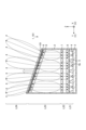
- FIG. 6 is a diagram showing an example of light distribution in the vertical direction (Y-axis direction).
- light L21 emitted from the light source 4 is converged into substantially parallel light by the condenser lens 6 (the linear Fresnel lens 6b on the upper surface) to become light L22.
- the light L22 is expanded in light distribution by the field lens 7 (the lenticular lens 7b on the upper surface) while keeping the optical axis as it is, and becomes light L23.
- the optical axis of the light L23 is tilted outward at each location by the field lens 8 (the linear prism 8b on the upper surface), the light distribution is spread outward, and the light L24 passes through the optical sheet 9 and the liquid crystal panel 101.
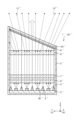
- FIG. 7 is a diagram showing a configuration example of a planar illumination device 1' and a liquid crystal panel 101' of Comparative Example #1 and an example of light distribution in the vertical direction (Y-axis direction).
- the planar lighting device 1' of Comparative Example #1 does not support local dimming. That is, the substrate 3', the light source 4', the reflector 5', the condenser lens 6', the field lens 8', the optical sheet 9' and the liquid crystal panel 101' are arranged in order from the bottom side of the frame 2'. The entire area is covered by the light source 4'.
- FIG. 8 is a diagram showing a configuration example of a planar illumination device 1′′ and a liquid crystal panel 101′′ of Comparative Example #2 and an example of light distribution in the vertical direction (Y-axis direction).
- the planar illumination device 1′′ of Comparative Example #2 is compatible with local dimming.
- a field lens 7'', a field lens 8'', an optical sheet 9'' and a liquid crystal panel 101'' are arranged in this order. However, the field lens 8'' is arranged parallel to the substrate 3'', the condenser lens 6'' and the field lens 7''.
- a uniform optical distance is secured between the field lens 8 and the liquid crystal panel 101. Therefore, light exceeding the local dimming zone area is suppressed, deterioration of contrast and brightness uniformity can be prevented, and contrast and brightness uniformity can be improved.
- the field lens 8 and the liquid crystal panel 101 are close to each other, their effects are exhibited more effectively.
- the present embodiment can also be applied to a normal backlight that is not compatible with local dimming, and exerts a certain effect. That is, in the case of the planar illumination device 1' that does not support local dimming in FIG. 7, light rays enter the frame 2' on the end side (the left end in FIG. 7) where the optical distance is the longest.
- the configuration of this embodiment it is possible to prevent the loss of light at the ends.
- the planar illumination device is two-dimensionally arranged on a substrate, a plurality of light sources whose light emission is individually controlled, and arranged parallel to the substrate on the emission side of the light sources, a condenser lens that converges the light emitted from the light source into substantially parallel light; the condenser lens is arranged on the exit side of the condenser lens, is inclined in at least one orthogonal direction in a plane parallel to the substrate, and is incident from the condenser lens. and a field lens that spreads light outward and secures a uniform optical distance with an externally attached liquid crystal panel. Thereby, contrast and luminance uniformity can be improved.
- the present embodiment can also be applied to a normal backlight that is not compatible with local dimming, and exerts a certain effect.
- the field lens is provided close to the liquid crystal panel. This allows the field lens to spread less light into adjacent dimming zones, resulting in less light loss and improved contrast.
- the condenser lens is a linear Fresnel lens in which the directions of the grooves forming unevenness on the incident side and the outgoing side are perpendicular to each other. A linear prism is formed. Thereby, a condenser lens can be easily realized.
- Another field lens is provided between the condenser lens and the field lens in parallel with the substrate. A lens is formed. As a result, luminance uniformity can be improved without incurring a decrease in light efficiency as in the case of a diffusion plate.
- a reflector is provided on the output side of the substrate and has a reflective surface surrounding the light source.
- optical sheet made up of a polarizing reflection sheet or a diffusion sheet, which is arranged on the output side of the obliquely arranged field lens. This facilitates realization of optical characteristics corresponding to the externally attached liquid crystal panel.
- a planar illumination device for illuminating a liquid crystal panel arranged at an angle with respect to an optical axis, comprising a plurality of light sources arranged two-dimensionally on a substrate, the light emission of which is controlled individually, and the emission of the light sources.
- a condenser lens that converges light emitted from the light source into substantially parallel light; and a field lens that is arranged on the emission side of the condenser lens and spreads outward the light that enters from the condenser lens. It is arranged parallel and close to the liquid crystal panel to which it is attached. Thereby, contrast and luminance uniformity can be improved.
- a planar illumination device for illuminating a liquid crystal panel arranged at an angle with respect to an optical axis, comprising a plurality of light sources arranged two-dimensionally on a substrate, the light emission of which is controlled individually, and the emission of the light sources.
- a condenser lens that converges light emitted from the light source into substantially parallel light; and a field lens that is arranged on the emission side of the condenser lens and spreads outward the light that enters from the condenser lens. It is placed close to the attached liquid crystal panel. Thereby, contrast and luminance uniformity can be improved.
- the field lens is close to the liquid crystal panel at a distance of 3 mm or less. Thereby, an effective effect can be expected.
- the present invention is not limited by the above-described embodiment.
- the present invention also includes those configured by appropriately combining the respective constituent elements described above. Further effects and modifications can be easily derived by those skilled in the art. Therefore, broader aspects of the present invention are not limited to the above-described embodiments, and various modifications are possible.
- 1 Planar illumination device 2 Frame, 3 Substrate, 4 Light source, 5 Reflector, 5a, 5b Reflective surface, 6 Condenser lens, 6a, 6b Linear Fresnel lens, 7 Field lens, 7a, 7b Lenticular lens, 8 Field lens, 8a , 8b linear prism, 9 optical sheet, 100 head-up display system, 101 liquid crystal panel, 101a display area, 101b frame, 102 mirror, 103 concave mirror, 104 window shield, EB eye box
Landscapes
- Physics & Mathematics (AREA)
- Nonlinear Science (AREA)
- General Physics & Mathematics (AREA)
- Optics & Photonics (AREA)
- Mathematical Physics (AREA)
- Chemical & Material Sciences (AREA)
- Crystallography & Structural Chemistry (AREA)
- Engineering & Computer Science (AREA)
- General Engineering & Computer Science (AREA)
- Planar Illumination Modules (AREA)
- Liquid Crystal (AREA)
Priority Applications (4)
| Application Number | Priority Date | Filing Date | Title |
|---|---|---|---|
| US18/836,913 US12504659B2 (en) | 2022-02-16 | 2022-12-28 | Planar illumination device with local dimming |
| KR1020247030854A KR102890256B1 (ko) | 2022-02-16 | 2022-12-28 | 면형상 조명 장치 |
| CN202280091807.3A CN118696198A (zh) | 2022-02-16 | 2022-12-28 | 面状照明装置 |
| EP22927382.6A EP4481265A1 (en) | 2022-02-16 | 2022-12-28 | Planar illumination device |
Applications Claiming Priority (2)
| Application Number | Priority Date | Filing Date | Title |
|---|---|---|---|
| JP2022-022222 | 2022-02-16 | ||
| JP2022022222A JP7406582B2 (ja) | 2022-02-16 | 2022-02-16 | 面状照明装置 |
Publications (1)
| Publication Number | Publication Date |
|---|---|
| WO2023157501A1 true WO2023157501A1 (ja) | 2023-08-24 |
Family
ID=87578065
Family Applications (1)
| Application Number | Title | Priority Date | Filing Date |
|---|---|---|---|
| PCT/JP2022/048623 Ceased WO2023157501A1 (ja) | 2022-02-16 | 2022-12-28 | 面状照明装置 |
Country Status (5)
| Country | Link |
|---|---|
| EP (1) | EP4481265A1 (enExample) |
| JP (2) | JP7406582B2 (enExample) |
| KR (1) | KR102890256B1 (enExample) |
| CN (1) | CN118696198A (enExample) |
| WO (1) | WO2023157501A1 (enExample) |
Families Citing this family (1)
| Publication number | Priority date | Publication date | Assignee | Title |
|---|---|---|---|---|
| JP7406582B2 (ja) * | 2022-02-16 | 2023-12-27 | ミネベアミツミ株式会社 | 面状照明装置 |
Citations (5)
| Publication number | Priority date | Publication date | Assignee | Title |
|---|---|---|---|---|
| JP2017151404A (ja) * | 2016-02-23 | 2017-08-31 | 株式会社デンソー | ヘッドアップディスプレイ装置 |
| JP2018083593A (ja) | 2016-11-25 | 2018-05-31 | 日本精機株式会社 | 表示装置 |
| JP2019061128A (ja) | 2017-09-27 | 2019-04-18 | 株式会社ジャパンディスプレイ | 表示装置およびヘッドアップ表示装置 |
| JP2020118935A (ja) * | 2019-01-28 | 2020-08-06 | 株式会社デンソー | 虚像表示装置 |
| WO2022004036A1 (ja) * | 2020-07-01 | 2022-01-06 | ミネベアミツミ株式会社 | 面状照明装置 |
Family Cites Families (3)
| Publication number | Priority date | Publication date | Assignee | Title |
|---|---|---|---|---|
| JP6508125B2 (ja) | 2016-05-18 | 2019-05-08 | 株式会社デンソー | ヘッドアップディスプレイ装置及び画像投射ユニット |
| EP3575846A1 (en) | 2018-05-30 | 2019-12-04 | Visteon Global Technologies Inc. | Picture generation unit for head-up display |
| JP7406582B2 (ja) | 2022-02-16 | 2023-12-27 | ミネベアミツミ株式会社 | 面状照明装置 |
-
2022
- 2022-02-16 JP JP2022022222A patent/JP7406582B2/ja active Active
- 2022-12-28 CN CN202280091807.3A patent/CN118696198A/zh active Pending
- 2022-12-28 KR KR1020247030854A patent/KR102890256B1/ko active Active
- 2022-12-28 EP EP22927382.6A patent/EP4481265A1/en active Pending
- 2022-12-28 WO PCT/JP2022/048623 patent/WO2023157501A1/ja not_active Ceased
-
2023
- 2023-12-15 JP JP2023212556A patent/JP7781130B2/ja active Active
Patent Citations (5)
| Publication number | Priority date | Publication date | Assignee | Title |
|---|---|---|---|---|
| JP2017151404A (ja) * | 2016-02-23 | 2017-08-31 | 株式会社デンソー | ヘッドアップディスプレイ装置 |
| JP2018083593A (ja) | 2016-11-25 | 2018-05-31 | 日本精機株式会社 | 表示装置 |
| JP2019061128A (ja) | 2017-09-27 | 2019-04-18 | 株式会社ジャパンディスプレイ | 表示装置およびヘッドアップ表示装置 |
| JP2020118935A (ja) * | 2019-01-28 | 2020-08-06 | 株式会社デンソー | 虚像表示装置 |
| WO2022004036A1 (ja) * | 2020-07-01 | 2022-01-06 | ミネベアミツミ株式会社 | 面状照明装置 |
Also Published As
| Publication number | Publication date |
|---|---|
| JP7406582B2 (ja) | 2023-12-27 |
| US20250035980A1 (en) | 2025-01-30 |
| JP2023119358A (ja) | 2023-08-28 |
| KR102890256B1 (ko) | 2025-11-25 |
| CN118696198A (zh) | 2024-09-24 |
| KR20240152353A (ko) | 2024-10-21 |
| JP2024022680A (ja) | 2024-02-16 |
| EP4481265A1 (en) | 2024-12-25 |
| JP7781130B2 (ja) | 2025-12-05 |
Similar Documents
| Publication | Publication Date | Title |
|---|---|---|
| CN103460114B (zh) | 平视显示装置 | |
| JP5287828B2 (ja) | ヘッドアップディスプレイ装置 | |
| TWI570478B (zh) | 面光源裝置及液晶顯示裝置 | |
| US7309149B2 (en) | Prism sheet, backlight assembly and liquid crystal display device having the same | |
| US8567977B2 (en) | Illumination system and display device | |
| JPH1196822A (ja) | 面照明装置およびこれを用いた表示装置 | |
| CN108885345A (zh) | 平视显示器装置 | |
| JP7781130B2 (ja) | 面状照明装置 | |
| WO2022004036A1 (ja) | 面状照明装置 | |
| JP7546185B1 (ja) | 面状照明装置 | |
| JP6984619B2 (ja) | 虚像表示装置 | |
| JP7769561B2 (ja) | 光学部材、光源装置、およびヘッドアップディスプレイ | |
| US12504659B2 (en) | Planar illumination device with local dimming | |
| JP3227802B2 (ja) | 液晶ディスプレイ用光学素子およびそれを用いた液晶ディスプレイ | |
| WO2022249557A1 (ja) | 面状照明装置 | |
| KR101101792B1 (ko) | 액정표시장치 및 조명장치 | |
| WO2022244350A1 (ja) | 面状照明装置 | |
| JP7495702B2 (ja) | 照明装置 | |
| JP2020109727A (ja) | バックライトユニットおよびヘッドアップディスプレイ装置 | |
| JPH0534686A (ja) | 面照明装置 | |
| JP2024015592A (ja) | 拡散部材、表示装置、ヘッドアップディスプレイ装置及び乗物 | |
| WO2023153278A1 (ja) | 光源装置、およびヘッドアップディスプレイ | |
| WO2025079542A1 (ja) | 面状照明装置 | |
| JP2022139536A (ja) | 表示装置 | |
| JP2022020391A (ja) | 面状照明装置 |
Legal Events
| Date | Code | Title | Description |
|---|---|---|---|
| 121 | Ep: the epo has been informed by wipo that ep was designated in this application |
Ref document number: 22927382 Country of ref document: EP Kind code of ref document: A1 |
|
| WWE | Wipo information: entry into national phase |
Ref document number: 18836913 Country of ref document: US |
|
| WWE | Wipo information: entry into national phase |
Ref document number: 202280091807.3 Country of ref document: CN |
|
| ENP | Entry into the national phase |
Ref document number: 20247030854 Country of ref document: KR Kind code of ref document: A |
|
| WWE | Wipo information: entry into national phase |
Ref document number: 1020247030854 Country of ref document: KR |
|
| WWE | Wipo information: entry into national phase |
Ref document number: 2022927382 Country of ref document: EP |
|
| NENP | Non-entry into the national phase |
Ref country code: DE |
|
| ENP | Entry into the national phase |
Ref document number: 2022927382 Country of ref document: EP Effective date: 20240916 |