WO2023157189A1 - 航空機、及び、回転翼モジュール - Google Patents
航空機、及び、回転翼モジュール Download PDFInfo
- Publication number
- WO2023157189A1 WO2023157189A1 PCT/JP2022/006426 JP2022006426W WO2023157189A1 WO 2023157189 A1 WO2023157189 A1 WO 2023157189A1 JP 2022006426 W JP2022006426 W JP 2022006426W WO 2023157189 A1 WO2023157189 A1 WO 2023157189A1
- Authority
- WO
- WIPO (PCT)
- Prior art keywords
- aircraft
- support
- opening
- rotor
- internal space
- Prior art date
- Legal status (The legal status is an assumption and is not a legal conclusion. Google has not performed a legal analysis and makes no representation as to the accuracy of the status listed.)
- Ceased
Links
Images


Classifications
-
- B—PERFORMING OPERATIONS; TRANSPORTING
- B64—AIRCRAFT; AVIATION; COSMONAUTICS
- B64C—AEROPLANES; HELICOPTERS
- B64C27/00—Rotorcraft; Rotors peculiar thereto
- B64C27/22—Compound rotorcraft, i.e. aircraft using in flight the features of both aeroplane and rotorcraft
- B64C27/26—Compound rotorcraft, i.e. aircraft using in flight the features of both aeroplane and rotorcraft characterised by provision of fixed wings
-
- B—PERFORMING OPERATIONS; TRANSPORTING
- B64—AIRCRAFT; AVIATION; COSMONAUTICS
- B64C—AEROPLANES; HELICOPTERS
- B64C29/00—Aircraft capable of landing or taking-off vertically, e.g. vertical take-off and landing [VTOL] aircraft
-
- B—PERFORMING OPERATIONS; TRANSPORTING
- B64—AIRCRAFT; AVIATION; COSMONAUTICS
- B64C—AEROPLANES; HELICOPTERS
- B64C29/00—Aircraft capable of landing or taking-off vertically, e.g. vertical take-off and landing [VTOL] aircraft
- B64C29/0008—Aircraft capable of landing or taking-off vertically, e.g. vertical take-off and landing [VTOL] aircraft having its flight directional axis horizontal when grounded
- B64C29/0016—Aircraft capable of landing or taking-off vertically, e.g. vertical take-off and landing [VTOL] aircraft having its flight directional axis horizontal when grounded the lift during taking-off being created by free or ducted propellers or by blowers
- B64C29/0025—Aircraft capable of landing or taking-off vertically, e.g. vertical take-off and landing [VTOL] aircraft having its flight directional axis horizontal when grounded the lift during taking-off being created by free or ducted propellers or by blowers the propellers being fixed relative to the fuselage
-
- B—PERFORMING OPERATIONS; TRANSPORTING
- B64—AIRCRAFT; AVIATION; COSMONAUTICS
- B64C—AEROPLANES; HELICOPTERS
- B64C29/00—Aircraft capable of landing or taking-off vertically, e.g. vertical take-off and landing [VTOL] aircraft
- B64C29/0091—Accessories not provided for elsewhere
-
- B—PERFORMING OPERATIONS; TRANSPORTING
- B64—AIRCRAFT; AVIATION; COSMONAUTICS
- B64C—AEROPLANES; HELICOPTERS
- B64C39/00—Aircraft not otherwise provided for
- B64C39/02—Aircraft not otherwise provided for characterised by special use
-
- B—PERFORMING OPERATIONS; TRANSPORTING
- B64—AIRCRAFT; AVIATION; COSMONAUTICS
- B64D—EQUIPMENT FOR FITTING IN OR TO AIRCRAFT; FLIGHT SUITS; PARACHUTES; ARRANGEMENT OR MOUNTING OF POWER PLANTS OR PROPULSION TRANSMISSIONS IN AIRCRAFT
- B64D27/00—Arrangement or mounting of power plants in aircraft; Aircraft characterised by the type or position of power plants
- B64D27/02—Aircraft characterised by the type or position of power plants
- B64D27/30—Aircraft characterised by electric power plants
- B64D27/34—All-electric aircraft
-
- B—PERFORMING OPERATIONS; TRANSPORTING
- B64—AIRCRAFT; AVIATION; COSMONAUTICS
- B64D—EQUIPMENT FOR FITTING IN OR TO AIRCRAFT; FLIGHT SUITS; PARACHUTES; ARRANGEMENT OR MOUNTING OF POWER PLANTS OR PROPULSION TRANSMISSIONS IN AIRCRAFT
- B64D27/00—Arrangement or mounting of power plants in aircraft; Aircraft characterised by the type or position of power plants
- B64D27/02—Aircraft characterised by the type or position of power plants
- B64D27/30—Aircraft characterised by electric power plants
- B64D27/35—Arrangements for on-board electric energy production, distribution, recovery or storage
- B64D27/357—Arrangements for on-board electric energy production, distribution, recovery or storage using batteries
-
- B—PERFORMING OPERATIONS; TRANSPORTING
- B64—AIRCRAFT; AVIATION; COSMONAUTICS
- B64D—EQUIPMENT FOR FITTING IN OR TO AIRCRAFT; FLIGHT SUITS; PARACHUTES; ARRANGEMENT OR MOUNTING OF POWER PLANTS OR PROPULSION TRANSMISSIONS IN AIRCRAFT
- B64D33/00—Arrangement in aircraft of power plant parts or auxiliaries not otherwise provided for
- B64D33/08—Arrangement in aircraft of power plant parts or auxiliaries not otherwise provided for of power plant cooling systems
Definitions
- the present invention relates to an aircraft and a rotor module.
- Aircraft that perform vertical take-off and landing are known.
- the aircraft described in Patent Literature 1 includes a fuselage, a pair of fixed wings extending laterally from the fuselage, and a plurality of rotor modules fixed to the pair of fixed wings.
- the rotor module supports a pair of rotor blades that are rotationally driven to generate a thrust that propels the aircraft vertically upward, a rotary drive section that drives the rotor blades by electric power, and a pair of rotor blades. and a support for The support extends in the longitudinal direction of the aircraft and has an interior space in which the rotary drive is accommodated.
- the support has a first opening that communicates the internal space with the outside of the support at a position vertically below the rotor blade on the outer surface in the vertical direction.
- the support has a second opening communicating between the internal space and the outside of the support at a position between the pair of rotor blades on the outer surface of the vertically downward direction.
- One of the purposes of the present invention is to cool the rotary drive part while suppressing the inflow of foreign matter.
- the aircraft performs vertical take-off and landing.
- An aircraft comprises a fuselage, at least one pair of fixed wings extending in the left-right direction from the fuselage, rotor blades that are rotationally driven to generate thrust for propelling the aircraft vertically upward, and rotor blades powered by electric power. and a support that extends in the longitudinal direction of the aircraft and has an internal space that accommodates at least a portion of the rotary drive and that supports the rotor blades. .
- the support includes a first opening forming portion having a first opening that communicates between the inner space of the support and the outside of the support at a position different from the downstream of the flow of air sent out by the rotation of the rotor; a second opening forming portion having a second opening communicating between the inner space of the support and the outside of the support, downstream of the flow of air delivered by the rotation of the rotor blade.
- the second opening forming part has a shape in which air in the inner space of the support flows out of the support due to a decrease in pressure in the vicinity of the second opening caused by the flow of air delivered by the rotation of the rotor blade.
- the rotor module is secured to fixed wings extending laterally from the fuselage of the aircraft.
- the rotor module includes rotor blades that generate thrust to propel the aircraft vertically upward by being rotationally driven, a rotary drive unit that drives the rotor blades to rotate by electric power, and a rotor module that extends in the longitudinal direction of the aircraft. and a support that has an internal space in which at least part of the rotary drive is accommodated and that supports the rotor.
- the support includes a first opening forming portion having a first opening that communicates between the inner space of the support and the outside of the support at a position different from the downstream of the flow of air sent out by the rotation of the rotor; a second opening forming portion having a second opening communicating between the inner space of the support and the outside of the support, downstream of the flow of air delivered by the rotation of the rotor blade.
- the second opening forming part has a shape in which air in the inner space of the support flows out of the support due to a decrease in pressure in the vicinity of the second opening caused by the flow of air delivered by the rotation of the rotor blade.
- FIG. 1 is a perspective view showing the configuration of an aircraft according to a first embodiment; FIG. It is a top view showing composition of an aircraft of a 1st embodiment. 1 is a front view showing the configuration of an aircraft according to a first embodiment; FIG. It is a rear view showing the structure of the aircraft of 1st Embodiment. 1 is a left side view showing the configuration of the aircraft of the first embodiment; FIG. It is a block diagram showing a schematic structure of the rotary blade module of the first embodiment.
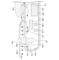
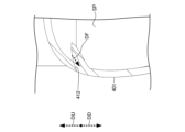
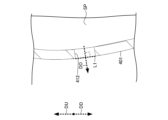
- FIG. 2 is a cross-sectional view of the rotor module of the first embodiment taken along a vertical plane orthogonal to the left-right direction of the aircraft;
- Figure 8 is a cross-sectional view of the rotor module through a vertical plane represented by line VIII-VIII in Figure 7;
- FIG. 9 is an enlarged cross-sectional view of the vicinity of the second opening forming portion of FIG. 8 ;
- FIG. 9 is an enlarged cross-sectional view of the vicinity of the second opening forming portion of FIG. 8 ;
- FIG. 4 is a cross-sectional view of a rotor module of a modified example of the first embodiment taken along a vertical plane perpendicular to the left-right direction of the aircraft; It is explanatory drawing which represents notionally the 2nd opening formation part of 1st Embodiment and a modification. It is explanatory drawing which represents notionally the 2nd opening formation part of the modification of 1st Embodiment.
- FIG. 5 is a cross-sectional view of a rotor module of a modification of the first embodiment taken along a vertical plane perpendicular to the longitudinal direction of the aircraft; 15 is an enlarged cross-sectional view of the vicinity of the second opening forming portion of FIG. 14; FIG.
- FIG. 15 is an enlarged cross-sectional view of the vicinity of the second opening forming portion of FIG. 14;
- FIG. FIG. 5 is a cross-sectional view of a rotor module of a modification of the first embodiment taken along a vertical plane perpendicular to the longitudinal direction of the aircraft;
- 18 is an enlarged cross-sectional view of the vicinity of the second opening forming portion of FIG. 17;
- FIG. 18 is an enlarged cross-sectional view of the vicinity of the second opening forming portion of FIG. 17;
- FIG. FIG. 5 is a cross-sectional view of a rotor module of a modification of the first embodiment taken along a vertical plane perpendicular to the longitudinal direction of the aircraft;
- 21 is an enlarged cross-sectional view of the vicinity of the second opening forming portion of FIG. 20;
- FIG. 21 is an enlarged cross-sectional view of the vicinity of the second opening forming portion of FIG. 20;
- FIG. 20 is an enlarged cross-sectional view of the vicinity of the
- FIG. 1 A block diagram illustrating an exemplary computing environment in accordance with the present invention.
- FIG. 1 A block diagram illustrating an exemplary computing environment in accordance with the present invention.
- the aircraft of the first embodiment performs vertical takeoff and landing.
- An aircraft comprises a fuselage, at least one pair of fixed wings extending in the left-right direction from the fuselage, rotor blades that are rotationally driven to generate thrust for propelling the aircraft vertically upward, and rotor blades powered by electric power. and a support that extends in the longitudinal direction of the aircraft and has an internal space that accommodates at least a portion of the rotary drive and that supports the rotor blades. .
- the support includes a first opening forming portion having a first opening that communicates between the inner space and the outside of the support at a position different from the downstream of the air flow sent out by the rotation of the rotor blade; a second opening formation having a second opening communicating between the interior space and the exterior of the support, downstream of the rotationally delivered air flow.
- the second opening forming part has a shape in which the air in the internal space flows out of the support body due to the pressure drop in the vicinity of the second opening due to the flow of air sent out by the rotation of the rotor blade.
- the air in the internal space is supported through the second opening located downstream of the air flow by the flow of the sent air. out of the body.
- the air flows into the internal space through the first opening having a different position from the downstream of the air flow.
- the rotary drive located in the inner space is cooled by the air flow in the inner space.
- the aircraft 1 performs vertical takeoff and landing.
- the aircraft 1 is an eVTOL (electric Vertical Take-Off and Landing) that flies the aircraft by electric power.
- the aircraft 1 flies in a vertical direction (in other words, ascends or descends in a vertical direction) in a vertical flight state (in other words, takeoff and landing state), and flies in a horizontal direction (in other words, cruises).
- the operating state is switched between a state of level flight (in other words, a cruising state).
- each direction (for example, up-down direction, front-rear direction, or left-right direction) described below is the direction in the takeoff/landing state.
- Each direction may be a direction in a cruising state.
- the upward direction and the downward direction are the vertically upward direction and the vertically downward direction, respectively.
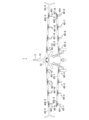
- the aircraft 1 includes a fuselage 10, a pair of front fixed wings 20-1, 20-2, and a pair of rear fixed wings 20-3, 20-4.
- the number of pairs of fixed wings included in the aircraft 1 may be one, or may be three or more.
- each of the pair of front fixed wings 20-1, 20-2 and the pair of rear fixed wings 20-3, 20-4 are simply fixed wings 20-j (j is 1 to represents an integer of 4.).
- the fuselage 10 extends in the front-rear direction of the aircraft 1 at the central portion in the left-right direction of the aircraft 1 .
- the fuselage 10 is composed of two rod-shaped or columnar bodies whose positions in the vertical direction of the aircraft 1 and positions in the longitudinal direction of the aircraft 1 are different from each other. It has shapes that are connected to each other.
- the fuselage 10 has a vertically downward end face of the forward end of the aircraft 1 located vertically below the vertically downward end face of the rearward end of the aircraft 1 .
- the fuselage 10 has a vertically upward end face of the forward end of the aircraft 1 located vertically below the vertically upward end face of the rearward end of the aircraft 1 .
- the fuselage 10 may be rod-shaped or column-shaped extending in the longitudinal direction of the aircraft 1 .
- the fuselage 10 may have a shape (in other words, a tapered shape) at each of both ends in the longitudinal direction of the aircraft 1 that tapers toward the tip.
- the length of the torso 10 in the front-rear direction may be 1 m to 15 m.
- a pair of forward fixed wings 20-1 and 20-2 are plate-shaped and extend from the fuselage 10 to the left of the aircraft 1 and to the right of the aircraft 1, respectively.
- Each of the pair of front fixed wings 20-1 and 20-2 has an airfoil shape in a cross section cut by a plane perpendicular to the left-right direction of the aircraft 1.
- the pair of front fixed wings 20-1 and 20-2 are symmetrical to each other with respect to a plane perpendicular to the left-right direction of the aircraft 1 and passing through the center of the fuselage 10 in the left-right direction.
- each of the pair of front fixed wings 20-1 and 20-2 may have a length of 0.5 m to 10 m in the horizontal direction.
- a pair of forward fixed wings 20-1 and 20-2 are located forward of the center of the fuselage 10 in the longitudinal direction of the aircraft 1. As shown in FIG. In this example, a pair of forward fixed wings 20-1 and 20-2 are located at the ends of the fuselage 10 in the forward direction.
- the pair of front fixed wings 20-1 and 20-2 are arranged in the longitudinal direction of the aircraft 1 from the front end of the fuselage 10 to the rear end of the pair of front fixed wings 20-1 and 20-2. has a position where the ratio of the distance to to the length of the fuselage 10 in the longitudinal direction of the aircraft 1 has a value between 0.01 and 0.4 (0.1 and 0.3 in this example).
- the pair of forward fixed wings 20-1, 20-2 are positioned forward of the center of gravity CG of the aircraft 1, as shown in FIG.
- a pair of forward fixed wings 20-1 and 20-2 are positioned below the center of the fuselage 10 in the vertical direction of the aircraft 1. As shown in FIG. In this example, the pair of forward fixed wings 20-1 and 20-2 are located at the ends of the fuselage 10 in the downward direction.
- the pair of front fixed wings 20-1 and 20-2 are arranged in the vertical direction of the aircraft 1 from the lower end of the fuselage 10 to the upper end of the pair of front fixed wings 20-1 and 20-2. to the height of the fuselage 10 in the vertical direction of the aircraft 1 (in this example, the maximum height of the fuselage 10 in the vertical direction of the aircraft 1 excluding tails 11-1 and 11-2 described later)
- the ratio has positions with values between 0.01 and 0.4 (0.05 and 0.2 in this example).
- the pair of front fixed wings 20-1 and 20-2 are positioned vertically below the center of gravity CG of the aircraft 1, as shown in FIG.
- a pair of rear fixed wings 20-3 and 20-4 are plate-shaped and extend from the fuselage 10 to the left of the aircraft 1 and to the right of the aircraft 1, respectively.
- Each of the pair of fixed rear wings 20-3 and 20-4 has an airfoil shape in a cross section cut by a plane perpendicular to the left-right direction of the aircraft 1.
- the pair of rear fixed wings 20-3 and 20-4 are symmetrical to each other with respect to a plane perpendicular to the left-right direction of the aircraft 1 and passing through the center of the fuselage 10 in the left-right direction.
- the length of each of the pair of rear fixed wings 20-3, 20-4 in the left-right direction is substantially equal to the length of each of the pair of front fixed wings 20-1, 20-2 in the left-right direction.
- the length of each of the pair of rear fixed wings 20-3 and 20-4 in the left-right direction is slightly longer than the length of each of the pair of front fixed wings 20-1 and 20-2 in the left-right direction. to long.
- each of the pair of rear fixed wings 20-3 and 20-4 may have a length of 0.5 m to 10 m in the lateral direction.
- a pair of rear fixed wings 20-3 and 20-4 are positioned rearward of the center of the fuselage 10 in the longitudinal direction of the aircraft 1. As shown in FIG. In this example, the pair of rear fixed wings 20-3 and 20-4 are positioned at the rearward end of the fuselage 10. As shown in FIG. For example, the pair of fixed aft wings 20-3, 20-4 extend from the aft end of the fuselage 10 to the forward end of the pair of aft fixed wings 20-3, 20-4 in the longitudinal direction of the aircraft 1. has a position where the ratio of the distance to to the length of the fuselage 10 in the longitudinal direction of the aircraft 1 has a value between 0.01 and 0.4 (0.1 and 0.3 in this example). In this example, the pair of rear fixed wings 20-3, 20-4 have a position behind the center of gravity CG of the aircraft 1, as shown in FIG.
- a pair of rear fixed wings 20-3 and 20-4 are positioned above the center of the fuselage 10 in the vertical direction of the aircraft 1. As shown in FIG. In this example, the pair of rear fixed wings 20-3 and 20-4 are positioned at the ends of the fuselage 10 in the upward direction.
- the pair of fixed rear wings 20-3 and 20-4 are arranged in the vertical direction of the aircraft 1 from the upper end of the fuselage 10 to the lower end of the pair of fixed rear wings 20-3 and 20-4. has a position where the ratio of the distance to to the height of the fuselage 10 in the vertical direction of the aircraft 1 is a value between 0.01 and 0.4 (0.05 and 0.2 in this example).
- the pair of rear fixed wings 20-3, 20-4 are positioned vertically above the center of gravity CG of the aircraft 1, as shown in FIG.
- the aircraft 1 has two pairs of fixed wings 20-1 to 20-4 whose positions in the longitudinal direction of the aircraft 1 are different from each other and whose positions in the vertical direction of the aircraft 1 are different from each other.
- the aircraft 1 has a pair of front fixed wings 20-1, 20-2, and is positioned behind the pair of front fixed wings 20-1, 20-2, and is positioned vertically. and a pair of rear fixed wings 20-3, 20-4 that are different in position from the pair of front fixed wings 20-1, 20-2.
- the pair of front fixed wings 20-1 and 20-2 correspond to the pair of first fixed wings.
- the pair of rear fixed wings 20-3, 20-4 correspond to the pair of second fixed wings.
- the pair of rear fixed wings 20-3 and 20-4 are positioned vertically above the pair of front fixed wings 20-1 and 20-2.
- the pair of rear fixed wings 20-3, 20-4 may be positioned vertically below the pair of front fixed wings 20-1, 20-2 in the vertical direction.
- the pair of front fixed wings 20-1, 20-2 are positioned vertically above the center of gravity CG of the aircraft 1
- the pair of rear fixed wings 20-3, 20-4 are: It may have a position vertically below the center of gravity CG of the aircraft 1 .
- the aircraft 1 includes a pair of fixed front wings 20-1, 20-2 and a pair of fixed rear wings 20-3, 20-4, and a plurality of (16 in this example) rotor blades. It has modules 40-1 to 40-16. Note that the number of rotor modules included in the aircraft 1 may be 2 to 15, or may be 17 or more. For example, the aircraft 1 may have 8, 12, 16, 20 or 24 rotor modules. The number of rotor blade modules fixed to each fixed blade 20-j is preferably two or more.
- the multiple rotor modules 40-1 to 40-16 are detachable to a pair of front fixed wings 20-1, 20-2 and a pair of rear fixed wings 20-3, 20-4. fixed to In addition, the plurality of rotor blade modules 40-1 to 40-16 are irremovably fixed to the pair of front fixed wings 20-1, 20-2 and the pair of rear fixed wings 20-3, 20-4. (For example, integrally formed).
- the four rotary wing modules 40-1 to 40-4 are fixed to the front fixed wing 20-1 located on the left side of the fuselage 10 out of the pair of front fixed wings 20-1 and 20-2.
- the four rotary wing modules 40-5 to 40-8 are fixed to the front fixed wing 20-2 located on the right side of the fuselage 10 out of the pair of front fixed wings 20-1 and 20-2.
- the four rotary wing modules 40-9 to 40-12 are fixed to the rear fixed wing 20-3 located on the left side of the fuselage 10 out of the pair of rear fixed wings 20-3 and 20-4.
- the four rotary wing modules 40-13 to 40-16 are fixed to the rear fixed wing 20-4 located on the right side of the fuselage 10 out of the pair of rear fixed wings 20-3 and 20-4. .
- Eight rotor modules 40-1 to 40-4, 40-9 to 40-12 positioned on the left side of the fuselage 10 and eight rotor modules 40-5 to 40 positioned on the right side of the fuselage 10 -8, 40-13 to 40-16 are symmetrical to each other with respect to a plane perpendicular to the left-right direction of the aircraft 1 and passing through the center of the fuselage 10 in the left-right direction.
- a rotary wing module 40-i (i represents an integer from 1 to 16) fixed to the fixed wing 20-j is positioned in a region other than the tip of the fixed wing 20-j in the horizontal direction of the aircraft 1. do.
- the rotor module 40-i fixed to the fixed wing 20-j is located at a distance from the tip of the fixed wing 20-j to the rotor module 40-i in the horizontal direction of the aircraft 1.
- the ratio of 1 to the length of the fixed wing 20-j in the lateral direction is greater than 0 and less than 1 (in this example, greater than 0 and less than or equal to 0.95).
- At least one of the rotary wing modules 40-i fixed to the fixed wing 20-j may be positioned at the tip of the fixed wing 20-j in the horizontal direction of the aircraft 1.
- rotor blade modules 40-k to 40-l (where k is an integer of 1, 5, 9, or 13, l is an integer of k+3) are fixed to the stationary blade 20-j. ) are positioned at equal intervals in the horizontal direction of the aircraft 1 . Note that the four rotor modules 40-k to 40-l fixed to the fixed wing 20-j may have different intervals in the horizontal direction of the aircraft 1.
- FIG. 1 illustrates that the four rotor blade modules 40-k to 40-l (where k is an integer of 1, 5, 9, or 13, l is an integer of k+3) are fixed to the stationary blade 20-j. ) are positioned at equal intervals in the horizontal direction of the aircraft 1 . Note that the four rotor modules 40-k to 40-l fixed to the fixed wing 20-j may have different intervals in the horizontal direction of the aircraft 1.
- the four rotor modules 40-k to 40-l fixed to the fixed wing 20-j are the four rotor modules 40-k to 40-l in the horizontal direction of the aircraft 1.
- the ratio of the distance between two rotor modules adjacent to each other to the length of the fixed wing 20-j in the lateral direction of the aircraft 1 is 0.1 to 0.4 (0.2 to 0.2 in this example). 0.3).
- the distance between two adjacent rotor modules among the four rotor modules 40-1 to 40-4 fixed to the front fixed wing 20-1 in the left-right direction of the aircraft 1 is and the distance between two adjacent rotor modules among the four rotor modules 40-9 to 40-12 fixed to the rear stationary wing 20-3 are equal to each other. Note that the distances between the two may be different from each other.
- four rotor modules 40-1 to 40-4 are fixed to the front fixed wing 20-1, and four rotor modules 40-9 to 40 are fixed to the rear fixed wing 20-3.
- -12 and -12 are substantially the same in the horizontal direction of the aircraft 1 .
- the positions of the four rotor modules 40-1 to 40-4 fixed to the front fixed wing 20-1 and the positions of the four rotor modules 40-1 to 40-4 fixed to the rear fixed wing 20-3 , and the positions of the rotor blade modules 40-9 to 40-12 coincide with each other. Note that the positions of both may be different from each other.
- four rotor modules 40-1 to 40-4 are fixed to the front fixed wing 20-1, and four rotor modules 40-9 to 40 are fixed to the rear fixed wing 20-3.
- -12 and -12 are different from each other in the vertical direction of the aircraft 1 .
- the four rotor modules 40-1 to 40-4 fixed to the front fixed wing 20-1 are connected to the four rotor modules 40-9 to 40 fixed to the rear fixed wing 20-3.
- -12 has a position downwards of aircraft 1;
- the four rotor modules 40-1 to 40-4 fixed to the front fixed wing 20-1 are replaced by the four rotor modules 40-9 to 40-12 fixed to the rear fixed wing 20-3. , may have a position above the aircraft 1 .
- FIG. 2 there are four rotor modules 40-1 to 40-4 fixed to the forward fixed wing 20-1 and four rotor modules 40-1 to 40-4 fixed to the rear fixed wing 20-3. are separated from each other in the longitudinal direction of the aircraft 1 when the aircraft 1 is viewed in the vertical direction.
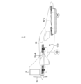
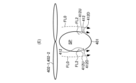
- the rotor module 40-i fixed to the stationary wing 20-j includes a support 401, a pair of first rotor blades 402-1 and 402-2, and a pair of Electric motors 403-1, 403-2, a pair of speed controllers 404-1, 404-2, a pair of first storage batteries 405-1, 405-2, a pair of circuit protectors 406-1, 406-2, a pair of circuit switches 407-1, 407-2, and a pair of controllers 408-1, 408-2.
- the support 401 extends forwardly of the fixed wing 20-j and rearwardly of the fixed wing 20-j in the longitudinal direction of the aircraft 1 (in other words, when the aircraft 1 is viewed in the vertical direction). It is rod-shaped or column-shaped extending in the front-rear direction.
- the support 401 is detachably fixed to the fixed wing 20-j at the central portion in the longitudinal direction of the aircraft 1. As shown in FIG.
- the support 401 has an internal space SP, which will be described later.
- the support 401 is positioned vertically below the fixed wing 20-j. Note that the support 401 may be positioned vertically above the fixed wing 20-j.
- Each of the pair of first rotor blades 402-1 and 402-2 is vertically above the support 401 so that the central axis of rotation extends in a direction whose main component is the vertical direction of the aircraft 1. It is rotatably supported by support 401 .
- a pair of first rotor blades 402-1 and 402-2 are rotationally driven by a pair of electric motors 403-1 and 403-2, respectively, to generate thrust for propelling aircraft 1 upward.
- the pair of first rotor blades 402-1 and 402-2 correspond to the pair of vertical rotor blades.
- the pair of first rotor blades 402-1 and 402-2 are positioned in front of the fixed wing 20-j and behind the fixed wing 20-j in the longitudinal direction of the aircraft 1, respectively.
- the pair of first rotor blades 402-1 and 402-2 are located at both ends of the support 401 in the longitudinal direction of the aircraft 1, respectively.
- the pair of first rotor blades 402-1, 402-2 are fixed wing 20 in the longitudinal direction of aircraft 1, the distance between the pair of first rotor blades 402-1, 402-2 in the longitudinal direction of aircraft 1. It may have positions where the ratio of -j to length is a value between 1.2 and 4.5 (2 and 3 in this example).
- Each of the pair of first rotor blades 402-1 and 402-2 has the shortest distance between the trajectory of the tip of the first rotor blade 402-1 and 402-2 and the fixed blade 20-j, It may have a position where the ratio to the length of the fixed wing 20-j in the longitudinal direction of the aircraft 1 is greater than 0 and less than or equal to 0.2 (a value of 0.02 to 0.08 in this example). .
- the vertical position of the pair of first rotor blades 402-1 and 402-2 is fixed by a plane passing through the central axis of rotation of the pair of first rotor blades 402-1 and 402-2. It is the position between the most vertically upward position and the most vertically downward position in the cross section of the blade 20-j.
- the pair of first rotor blades 402-1 and 402-2 are connected to the fixed wing 20- It has a position that overlaps with j.
- the pair of first rotor blades 402-1 and 402-2 rotate in different directions.
- the two first rotor blades 402-1 adjacent in the left-right direction of the aircraft 1 have different rotational directions, and the two first rotor blades 402-1 adjacent in the left-right direction of the aircraft 1 2 differ from each other in the direction of rotation.
- the two first rotor blades 402-1 and 402-2 that are adjacent in the vertical direction of the aircraft 1 rotate in different directions.
- the first rotor blades 402-1, 402-2 may be referred to as rotors.
- the configuration for rotationally driving the first rotor blade 402-1 (in this example, the electric motor 403-1, the speed controller 404-1, the first storage battery 405-1, the circuit protector 406-1, the circuit switch 407-1 and controller 408-1) are described.
- the configuration for rotationally driving the first rotor blade 402-2 (in this example, the electric motor 403-2, the speed controller 404-2, the first storage battery 405-2, the circuit protector 406-2, the circuit switch 407-2 and controller 408-2) will be described in the same manner as the configuration for rotationally driving the first rotor blade 402-1, so description thereof will be omitted.
- speed controller 404-1, first storage battery 405-1, circuit protector 404-1, first storage battery 405-1, and circuit protector 404-1 as shown in FIG.
- the device 406-1, the circuit switch 407-1, and the controller 408-1 are housed in the internal space SP of the support 401.
- part of the electric motor 403 - 1 is also housed in the internal space SP of the support 401 .
- FIG. 7 the illustration of cables through which current flows and signal lines through which control signals are transmitted is omitted. Note that the entire electric motor 403 - 1 may be housed in the internal space SP of the support 401 . Alternatively, the entire electric motor 403 - 1 may be located outside the support 401 .
- the electric motor 403-1 rotates the first rotor blade 402-1 according to the power supplied from the speed controller 404-1.
- Speed controller 404-1 controls the rotational speed (in other words, number of revolutions) of first rotor blade 402-1 rotationally driven by electric motor 403-1, according to a control signal transmitted from controller 408-1. , the power supplied to the electric motor 403-1 is controlled.
- the speed controller 404-1 may be represented as an ESC (Electric Speed Controller).
- the first storage battery 405-1 charges and discharges power.
- the first storage battery 405-1 includes a plurality of single cells (in other words, cells) connected in series.
- the first battery 405-1 has a voltage between 24V and 120V.
- First storage battery 405-1 supplies power to motor 403-1 via circuit protector 406-1, circuit switch 407-1, and speed controller 404-1.
- the first storage battery 405-1 is fixed to the support 401.
- the first storage battery 405-1 is positioned between the pair of first rotors 402-1 and 402-2 in the longitudinal direction of the aircraft 1.
- the first storage battery 405-1 is located in the center of the support 401 in the longitudinal direction of the aircraft 1.
- first battery 405-1 is located below fixed wing 20-j.
- First storage battery 405-1 may be positioned between first rotor 402-1 and fixed wing 20-j in the longitudinal direction of aircraft 1.
- Circuit protector 406-1 is provided between speed controller 404-1 and first storage battery 405-1 when current supplied from first storage battery 405-1 to speed controller 404-1 exceeds a predetermined threshold. If it exceeds, cut off the current.
- circuit protector 406-1 may be represented as a power fuse.
- the circuit switch 407-1 is controlled between the speed controller 404-1 and the first storage battery 405-1 (in this example, between the circuit protector 406-1 and the speed controller 404-1). According to the control signal transmitted from the device 408-1, the ON state permitting current to be supplied from the first storage battery 405-1 to the speed controller 404-1, and the first storage battery 405-1 to the speed controller 404 -1 (in other words, the current supply from the first storage battery 405-1 to the speed controller 404-1 is cut off), and the operating state is switched between the OFF state.
- circuit switch 407-1 is a contactor.
- Controller 408-1 controls speed controller 404-1 and circuit switch 407-1 according to control signals transmitted from controller 13, which will be described later.
- electric motor 403-1, speed controller 404-1, first storage battery 405-1, circuit protector 406-1, circuit switch 407-1, and controller 408-1 are powered by the first It corresponds to a rotation drive unit that rotates the rotor blade 402-1.
- the aircraft 1 can fly above the aircraft 1 from the pair of first rotor blades 402-1 and 402-2 provided in each of the plurality of rotor blade modules 40-1 to 40-16. Vertical take-off and landing are performed by the thrust that propels it in the direction.
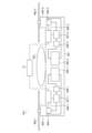
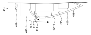
- FIG. 8 represents a cross-section of rotor module 40-i through a vertical plane represented by line VIII-VIII in FIG.
- the support 401 includes a first opening forming portion 411 and a plurality of second opening forming portions 412 .
- the number of the second opening forming portions 412 included in the support 401 is eight.
- the number of second opening forming portions 412 included in the support 401 may be 1 to 7, or may be 9 or more.
- the first opening forming portion 411 is located at a position different from the downstream of the air flow FL0 sent out by the rotation of the first rotor blades 402-1 and 402-2, between the inner space SP of the support 401 and the support 401. It has a first opening communicating with the outside.
- the first opening forming portion 411 is positioned vertically below the fixed wing 20-j.
- the first opening forming portion 411 faces the end surface of the fixed wing 20-j in the vertical direction.
- the first opening forming portion 411 may be positioned on an end face (in other words, a side face) of the support 401 in the horizontal direction of the aircraft 1 vertically below the fixed wing 20-j.
- the first opening forming part 411 may be located at the end of the support 401 in the vertical downward direction of the aircraft 1, vertically below the fixed wing 20-j.
- the first opening forming portion 411 is a portion of the support 401 other than the portion vertically below the fixed wing 20-j, and is positioned at the end of the support 401 in the vertical direction below the aircraft 1. You may have
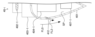
- each of the plurality of second opening forming portions 412 is located downstream of the air flow FL0 delivered by the rotation of the first rotor blades 402-1 and 402-2. It has a second opening that communicates the internal space SP of 401 with the outside of the support 401 .
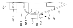
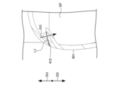
- FIG. 9 which is an enlarged view of the second opening forming portion 412 in FIG.
- the opening direction DO which is orthogonal to the straight line L1 connecting the two ends forming the two openings and is the direction from the internal space SP of the support 401 toward the outside of the support 401, does not have a vertically upward component DU. (In other words, it is orthogonal to the vertical direction or has a vertically downward component DD).
- the air flow FL0 delivered by the rotation of the first rotor blades 402-1 and 402-2 reduces the pressure in the vicinity of the second opening forming portion 412, thereby causing the second opening forming portion 412 to close to the support body. It has a shape in which the air in the internal space SP of 401 flows out to the outside of the support 401 .
- the support 401 is provided with the first opening 401 when the aircraft 1 and the first rotors 402-1 and 402-2 are stationary.
- the outflow direction DF which is the direction in the center of the second opening, of the air flowing out from the second opening does not have a vertically upward component DU.
- the second opening forming part 412 is located on the outer surface of the support 401 in each of the lateral directions of the aircraft 1 .
- the second opening forming portion 412 may be positioned on the outer surface of the support 401 in either one of the lateral directions of the aircraft 1 .
- the second opening forming part 412 may be located on the outer surface of the support 401 closer to the fuselage 10 in the lateral direction of the aircraft 1 .
- the second opening forming portion 412 may be positioned on the outer surface of the support 401 in the lateral direction of the aircraft 1 farther from the fuselage 10 .
- the second opening forming portion 412 is formed on the outer surface of the support 401 in each of the longitudinal directions of the aircraft 1 with respect to the central axis of rotation of the first rotor blades 402-1 and 402-2. To position. The second opening forming portion 412 is formed on the outer surface of the support 401 in one of the longitudinal directions of the aircraft 1 with respect to the central axis of rotation of the first rotor blades 402-1 and 402-2. may be located. In this case, the second opening forming portion 412 is located at the center of the support 401 in the longitudinal direction of the aircraft 1 with respect to the central axis of rotation of the first rotor blades 402-1 and 402-2 of the support 401. It may be located on the outer surface closer to the part.
- the second opening forming portion 412 is formed in the central portion of the support 401 in the longitudinal direction of the aircraft 1 with respect to the central axis of rotation of the first rotor blades 402-1 and 402-2. may be located on the outer surface farthest from the
- the support 401 may be positioned such that the plurality of second opening forming portions 412 are adjacent to each other in the longitudinal direction of the aircraft 1 . Further, the support 401 may be positioned such that the plurality of second opening forming portions 412 are adjacent to each other in the vertical direction of the aircraft 1 .
- a pair of first rotor blades provided in each of the four rotor blade modules 40-1 to 40-4 fixed to the front fixed blade 20-1 402-1 and 402-2 are a pair of first rotor blades 402-1 and 402-2 provided in each of the four rotor blade modules 40-9 to 40-12 fixed to the rear fixed wing 20-3. has a position below aircraft 1 than .
- a pair of first rotor blades 402-1 and 402-2 included in each of the four rotor blade modules 40-1 to 40-4 fixed to the front fixed blade 20-1 is connected to the rear fixed blade 20- 3 is positioned above the aircraft 1 relative to the pair of first rotor blades 402-1 and 402-2 provided in each of the four rotor blade modules 40-9 to 40-12 fixed to 3.
- the first rotor 402-1 included in each of the four rotor modules 40-9 to 40-12 fixed to the fixed wing 20-3 is the aircraft 1 are separated from each other in the fore-and-aft direction.
- the fuselage 10 has an internal space that accommodates objects to be transported.
- the internal space is located between a pair of front fixed wings 20-1, 20-2 and a pair of rear fixed wings 20-3, 20-4 in the longitudinal direction of the aircraft 1.
- the internal space is located in the center of the aircraft 1 in the longitudinal direction.
- Transportation targets include at least one of people and objects.
- a person included in a transport object may be designated as a passenger.
- passengers may fly the aircraft 1 .
- the aircraft 1 is configured to fly by autopilot, the passengers do not need to operate the aircraft 1 .
- the objects included in the transport object are cargo or luggage.
- the interior space of fuselage 10 may accommodate one to five passengers.
- the interior space of the fuselage 10 can accommodate one or two passengers.
- the maximum takeoff weight of the aircraft 1 may be between 120 kg and 3000 kg. In this example, the maximum takeoff weight of the aircraft 1 is between 150 kg and 460 kg.
- the body 10 includes a door (cowl in this example) that can open and close the accommodation space.
- the fuselage 10 includes a tail 11, a second rotor 12, and a control device 13. Note that the number of tail wings provided in the body 10 may be two or more.
- the tail 11 is located at the rearward end of the fuselage 10 .
- the tail 11 has a plate shape extending along a plane orthogonal to the left-right direction of the aircraft 1 .
- the tail 11 extends upward from the aircraft 1 from the fuselage 10 .
- the second rotor blade 12 is rotatably supported by the fuselage 10 so that the central axis of rotation extends in a direction whose main component is the longitudinal direction of the aircraft 1 .
- the aircraft 1 comprises a second storage battery, a speed controller and an electric motor (not shown).
- the second rotor blade 12 is rotationally driven according to the electric power supplied from the second storage battery.
- the aircraft 1 has a speed controller controlling the power supplied from the second battery to the electric motor so as to control the rotational speed of the second rotor 12 .
- the second storage battery is housed in the body 10 .
- the second storage battery may be housed in the fixed wing 20-j instead of or in addition to the fuselage 10.
- the second rotor blade 12 is rotationally driven by an electric motor to generate a thrust that propels the aircraft 1 forward.
- the aircraft 1 has the thrust generated by the second rotor 12 that propels the aircraft 1 forward, the pair of front fixed wings 20-1 and 20-2, and the pair of rear It flies horizontally due to the lift generated by the fixed wings 20-3 and 20-4.
- the second rotor blade 12 is located at the rearward end of the fuselage 10 .
- the second rotor blade 12 may be positioned at a portion other than the rear end of the body 10 (for example, the front end of the body 10, or the center of the body 10 in the longitudinal direction). .
- the number of the second rotor blades 12 included in the body 10 may be two or more.
- the plurality of second rotor blades 12 may be positioned at both the forward end of the fuselage 10 and the rearward end of the fuselage 10, or may be positioned at only one of them. may be located.
- the plurality of second rotor blades 12 are positioned on at least one of the pair of front fixed blades 20-1, 20-2 and the pair of rear fixed blades 20-3, 20-4.
- the second rotor 12 may be represented as a propeller.
- the second rotor 12 corresponds to the horizontal rotor.
- the control device 13 is housed in the body 10.
- the controller 13 controls the aircraft 1 by operating with electric power.
- the control device 13 includes electronic equipment that acquires information representing the state of the aircraft 1 (eg, altitude, longitude, latitude, speed, etc.).
- controller 13 includes avionics (eg, communication equipment, navigation systems, flight management systems, etc.).
- control device 13 generates a control signal according to the operation of the passenger, and based on the generated control signal, the first rotor blades 402-1, 402-1, and 402-1 of the plurality of rotor blade modules 40-1 to 40-16. 402-2 and the rotation speed of each of the second rotor blades 12 are controlled.
- the aircraft 1 rotates each of the 16 pairs of first rotor blades 402-1 and 402-2 respectively provided in the 16 rotor blade modules 40-1 to 40-16. This generates a thrust that propels the aircraft 1 upward. As a result, the aircraft 1 takes off by flying vertically upward (in other words, ascending).
- the flow of the sent air causes the air in the internal space SP of the support 401 to change the flow of the air. flows out of the support 401 through a second opening located downstream of the .
- the air flows into the internal space SP of the support 401 through the first opening having a position different from the downstream of the air flow.
- the rotation drive unit in this example, the electric motor 403-1, the speed controller 404-1, the first storage battery 405-1, the circuit protector 406-1, the circuit switch located in the internal space SP of the support 401 407-1 and controller 408-1) are cooled by air flow in the internal space SP.
- the aircraft 1 drives the second rotor 12 to rotate. This generates a thrust that propels the aircraft 1 forward. As a result, the pair of front fixed wings 20-1, 20-2 and the pair of rear fixed wings 20-3, 20-4 generate lift. Next, the aircraft 1 stops rotating the 16 pairs of first rotor blades 402-1 and 402-2 provided in the 16 rotor blade modules 40-1 to 40-16, respectively. As a result, the aircraft 1 flies horizontally (in other words, cruises).
- the aircraft 1 rotates each of the 16 pairs of first rotor blades 402-1 and 402-2 respectively provided in the 16 rotor blade modules 40-1 to 40-16. This generates a thrust that propels the aircraft 1 upward.
- the aircraft 1 stops the rotational drive of the second rotor 12 . As a result, the aircraft 1 flies vertically downward (in other words, descends).
- the flow of the sent air causes the air in the internal space SP of the support 401 to change the flow of the air. flows out of the support 401 through a second opening located downstream of the .
- the air flows into the internal space SP of the support 401 through the first opening having a position different from the downstream of the air flow.
- the rotary drive located in the internal space SP of the support 401 is cooled by the air flow in the internal space SP. Aircraft 1 then lands.
- the aircraft 1 of the first embodiment performs vertical takeoff and landing.
- the aircraft 1 has a fuselage 10, at least one pair of fixed wings 20-1 to 20-4 extending in the left-right direction from the fuselage 10, and a thrust that propels the aircraft 1 vertically upward by being rotationally driven.
- a rotation drive unit in this example, an electric motor 403-1, a speed controller 404-1, a third 1 storage battery 405-1, circuit protector 406-1, circuit switch 407-1, and controller 408-1
- a rotation drive unit in this example, an electric motor 403-1, a speed controller 404-1, a third 1 storage battery 405-1, circuit protector 406-1, circuit switch 407-1, and controller 408-1
- the support 401 communicates the internal space SP of the support 401 with the outside of the support 401 at a position different from the downstream of the air flow FL0 delivered by the rotation of the rotor blades 402-1 and 402-2.
- the inner space SP of the support 401 and the inner space SP of the support 401 are located downstream of the air flow FL0 sent out by the rotation of the first opening forming part 411 having the first opening and the rotation of the rotor blades 402-1 and 402-2. and a second opening forming portion 412 having a second opening communicating with the outside.
- the inner space SP of air flows out to the outside of the support 401 .
- the delivered air flow causes the air in the internal space SP to flow downstream of the air flow FL0. It flows out of the support 401 through the second opening located there. As a result, the air flows into the internal space SP through the first opening having a different position from the downstream of the air flow FL0. As a result, the rotary drive section located in the internal space SP is cooled by the air flow in the internal space SP.
- the air does not flow into the internal space SP downstream of the air flow FL0 delivered by the rotation of the rotor blades 402-1 and 402-2. Therefore, even if foreign matter is contained in the air delivered by the rotation of the rotor blades 402-1 and 402-2, it is possible to prevent the foreign matter from flowing into the internal space SP. That is, according to the aircraft 1, the rotary drive section can be cooled while suppressing the inflow of foreign matter.
- the outflow direction DF which is the direction in the center of the second opening, of the flow of air flowing out from the second opening does not have a component in the vertically upward direction DU.
- the flow of the sent air can sufficiently reduce the pressure in the vicinity of the second opening.
- the second opening forming part 412 connects two ends of the outer surface of the support 401 that form the second opening in a vertical cross section of the support 401.
- the opening direction DO which is perpendicular to the straight line L1 and extends from the internal space SP toward the outside of the support 401, does not have a component of the vertically upward direction DU.
- the flow of the sent air can sufficiently reduce the pressure in the vicinity of the second opening. Furthermore, compared to the case where the opening direction DO has a vertically upward component DU, it is possible to further suppress foreign matter from flowing into the internal space SP through the second opening.
- the support 401 is positioned vertically below the fixed wing 20-j and extends from the front of the fixed wing 20-j to the rear of the fixed wing 20-j. do. Furthermore, the first opening forming portion 411 is positioned vertically below the fixed wing 20-j.
- the first opening is shielded from falling foreign matter by the fixed wings. Therefore, foreign matter can be suppressed from flowing into the internal space SP.
- the rotary drive section includes electric motors 403-1 and 403-2 that drive rotary wings 402-1 and 402-2.
- the rotary drive section includes speed controllers 404-1 and 404-2 that control the rotational speeds of the rotor blades 402-1 and 402-2.
- the speed controllers 404-1 and 404-2 generate heat. Therefore, according to the aircraft 1, when the rotor blades 402-1 and 402-2 are rotationally driven, it is possible to prevent the temperature of the rotational drive section from becoming excessively high.
- the rotation drive section includes first storage batteries 405-1 and 405-2 that supply electric power to rotate the rotor blades 402-1 and 402-2.
- the first storage batteries 405-1 and 405-2 generate heat. Therefore, according to the aircraft 1, when the rotor blades 402-1 and 402-2 are rotationally driven, it is possible to prevent the temperature of the rotational drive section from becoming excessively high.
- the second opening forming portion 412 is located on the outer surface of the support 401 in the left-right direction of the aircraft 1 .
- the support 401 extends in the longitudinal direction of the aircraft 1, the length of the second opening in the longitudinal direction of the aircraft 1 can be increased. Therefore, the flow rate of air flowing out from the internal space SP of the support 401 can be increased. As a result, it is possible to cool the rotary drive portion located in the internal space SP with high efficiency.
- the support 401 seals a portion of the internal space SP, which is different from the first opening and the second opening, against the gas.
- a shield 4011 is provided.
- the shield 4011 covers the inner wall surface of the support 401 forming the inner space SP, other than the first opening and the second opening.
- the flow rate of air flowing in from the first opening can be increased. Therefore, it is possible to efficiently cool the rotary drive section located in the internal space SP of the support 401 .
- the second opening forming portion 412 of the first embodiment has a normal direction to the outer surface of the support 401, which is vertically downward. of the edge forming the second opening, the portion 412D on the vertically downward side is positioned more inward of the support 401 than the portion 412U on the vertically upward side. It has a concave shape.
- the second opening forming portion 412 of the modified example of the first embodiment as shown in FIG.
- the direction is located in a region having a vertically upward component, and of the edge forming the second opening, the vertically downward portion 412D is located further inside the support 401 than the vertically upward portion 412U. It may have a concave shape so as to be positioned on the side.
- the second opening forming portion 412 of the modification of the first embodiment has a normal to the outer surface of the support 401 among the outer surfaces of the support 401, as shown in FIG. 12C.
- the direction is located in a region having a vertically downward component, and of the edges forming the second opening, the vertically upward portion 412U is located outside the support 401 than the vertically downward portion 412D. You may have the shape which protruded so that it may be located toward the direction.
- the second opening forming portion 412 of the modification of the first embodiment has a normal to the outer surface of the support 401 among the outer surfaces of the support 401. As shown in FIG. The direction is located in a region having a vertically upward component, and of the edge forming the second opening, the vertically upward portion 412U is located outside the support 401 than the vertically downward portion 412D. You may have the shape which protruded so that it may be located toward the direction.
- the second opening forming portion 412 of the modification of the first embodiment as shown in FIG.
- the direction is located in a region having a vertically downward component, and the vertically upward side portion 412U of the edge forming the second opening extends vertically downward along the outer surface of the support 401.
- FIG. 14 showing a cross section of the rotor module 40-i along the vertical plane and FIG. in the cross section along the vertical plane of the support 401, perpendicular to the straight line L1 connecting the two ends forming the second opening of the outer surface of the support 401, and from the internal space SP of the support 401 to the outside of the support 401
- the opening direction DO which is the facing direction, does not have a vertically upward direction DU component.
- the support 401 is provided with the first opening 402 in a state in which the aircraft 1 and the first rotors 402-1 and 402-2 are stationary.
- the outflow direction DF which is the direction in the center of the second opening, of the air flowing out from the second opening does not have a vertically upward component DU.
- FIG. 17 showing a vertical section of the rotor module 40-i and in FIG. in the cross section along the vertical plane of the support 401, perpendicular to the straight line L1 connecting the two ends forming the second opening of the outer surface of the support 401, and from the internal space SP of the support 401 to the outside of the support 401
- the opening direction DO which is the facing direction, does not have a vertically upward direction DU component.
- the support 401 is provided with the first opening 402 in a state in which the aircraft 1 and the first rotors 402-1 and 402-2 are stationary.
- the outflow direction DF which is the direction in the center of the second opening, of the air flowing out from the second opening does not have a vertically upward component DU.
- FIG. 20 showing a cross section of the rotor module 40-i along the vertical plane and FIG. in the cross section along the vertical plane of the support 401, perpendicular to the straight line L1 connecting the two ends forming the second opening of the outer surface of the support 401, and from the internal space SP of the support 401 to the outside of the support 401
- the opening direction DO which is the facing direction, does not have a vertically upward direction DU component.
- the support 401 is provided with the first opening 401 when the aircraft 1 and the first rotors 402-1 and 402-2 are stationary.
- the outflow direction DF which is the direction in the center of the second opening, of the air flowing out from the second opening does not have a vertically upward component DU.
Landscapes
- Engineering & Computer Science (AREA)
- Aviation & Aerospace Engineering (AREA)
- Mechanical Engineering (AREA)
- Chemical & Material Sciences (AREA)
- Combustion & Propulsion (AREA)
- Toys (AREA)
- Structures Of Non-Positive Displacement Pumps (AREA)
Priority Applications (3)
| Application Number | Priority Date | Filing Date | Title |
|---|---|---|---|
| PCT/JP2022/006426 WO2023157189A1 (ja) | 2022-02-17 | 2022-02-17 | 航空機、及び、回転翼モジュール |
| JP2024500824A JP7515948B2 (ja) | 2022-02-17 | 2022-02-17 | 航空機、及び、回転翼モジュール |
| US18/806,869 US20250042543A1 (en) | 2022-02-17 | 2024-08-16 | Aircraft and rotor blade module |
Applications Claiming Priority (1)
| Application Number | Priority Date | Filing Date | Title |
|---|---|---|---|
| PCT/JP2022/006426 WO2023157189A1 (ja) | 2022-02-17 | 2022-02-17 | 航空機、及び、回転翼モジュール |
Related Child Applications (1)
| Application Number | Title | Priority Date | Filing Date |
|---|---|---|---|
| US18/806,869 Continuation US20250042543A1 (en) | 2022-02-17 | 2024-08-16 | Aircraft and rotor blade module |
Publications (1)
| Publication Number | Publication Date |
|---|---|
| WO2023157189A1 true WO2023157189A1 (ja) | 2023-08-24 |
Family
ID=87577924
Family Applications (1)
| Application Number | Title | Priority Date | Filing Date |
|---|---|---|---|
| PCT/JP2022/006426 Ceased WO2023157189A1 (ja) | 2022-02-17 | 2022-02-17 | 航空機、及び、回転翼モジュール |
Country Status (3)
| Country | Link |
|---|---|
| US (1) | US20250042543A1 (https=) |
| JP (1) | JP7515948B2 (https=) |
| WO (1) | WO2023157189A1 (https=) |
Families Citing this family (1)
| Publication number | Priority date | Publication date | Assignee | Title |
|---|---|---|---|---|
| CN120697955A (zh) * | 2022-11-14 | 2025-09-26 | 阿切尔航空公司 | 用于vtol航空器中的马达冷却的系统和方法 |
Citations (4)
| Publication number | Priority date | Publication date | Assignee | Title |
|---|---|---|---|---|
| JP2016175489A (ja) * | 2015-03-19 | 2016-10-06 | セコム株式会社 | 飛行装置 |
| US20180105268A1 (en) * | 2016-10-18 | 2018-04-19 | Kitty Hawk Corporation | Ventilated rotor mounting boom for personal aircraft |
| JP2020055387A (ja) * | 2018-10-01 | 2020-04-09 | 本田技研工業株式会社 | 飛翔装置 |
| DE102018217144A1 (de) * | 2018-10-08 | 2020-04-09 | Nickel Holding Gmbh | Drohne mit gekühlter Batterie |
Family Cites Families (3)
| Publication number | Priority date | Publication date | Assignee | Title |
|---|---|---|---|---|
| GB2537935B (en) | 2015-05-01 | 2021-02-24 | Intelligent Energy Ltd | Aerial vehicle |
| JP7225886B2 (ja) | 2019-02-14 | 2023-02-21 | ウシオ電機株式会社 | 飛行体 |
| CN213974458U (zh) | 2020-08-07 | 2021-08-17 | 上海峰飞航空科技有限公司 | 垂直起降空中无人机以及用于空中无人机的冷却系统 |
-
2022
- 2022-02-17 WO PCT/JP2022/006426 patent/WO2023157189A1/ja not_active Ceased
- 2022-02-17 JP JP2024500824A patent/JP7515948B2/ja active Active
-
2024
- 2024-08-16 US US18/806,869 patent/US20250042543A1/en active Pending
Patent Citations (4)
| Publication number | Priority date | Publication date | Assignee | Title |
|---|---|---|---|---|
| JP2016175489A (ja) * | 2015-03-19 | 2016-10-06 | セコム株式会社 | 飛行装置 |
| US20180105268A1 (en) * | 2016-10-18 | 2018-04-19 | Kitty Hawk Corporation | Ventilated rotor mounting boom for personal aircraft |
| JP2020055387A (ja) * | 2018-10-01 | 2020-04-09 | 本田技研工業株式会社 | 飛翔装置 |
| DE102018217144A1 (de) * | 2018-10-08 | 2020-04-09 | Nickel Holding Gmbh | Drohne mit gekühlter Batterie |
Also Published As
| Publication number | Publication date |
|---|---|
| JPWO2023157189A1 (https=) | 2023-08-24 |
| US20250042543A1 (en) | 2025-02-06 |
| JP7515948B2 (ja) | 2024-07-16 |
Similar Documents
| Publication | Publication Date | Title |
|---|---|---|
| US11066161B2 (en) | Electrically or hybrid powered multirotor aircraft with optimized energy consumption | |
| US11208207B2 (en) | Vertical takeoff and landing (VTOL) aircraft | |
| CN110035954B (zh) | 用于私人飞机的通风旋翼安装臂架 | |
| US10676180B2 (en) | Multi-rotor personal air vehicle with a central lifting fan | |
| US12420920B2 (en) | Aerial vehicle such as high speed drone | |
| US10994838B2 (en) | Vertical takeoff and landing aircraft | |
| US20190389573A1 (en) | Vertical take-off and landing unmanned aerial vehicle | |
| JP2020131781A (ja) | 飛行体 | |
| EP4105125B1 (en) | Series of convertible aircrafts capable of hovering and method for configuring a convertible aircraft capable of hovering | |
| US20240002034A1 (en) | Ducted Wing with Flaps | |
| CN117460667A (zh) | 能够悬停的可转换的飞行器的系列和用于构造能够悬停的可转换的飞行器的方法 | |
| US20250042543A1 (en) | Aircraft and rotor blade module | |
| WO2025122212A2 (en) | Exhaust area and flow turning control | |
| US20260048838A1 (en) | Aircraft capable of hovering and relative control method | |
| US20250172947A1 (en) | Flying apparatus, aircraft, and method for controlling flight of flying apparatus | |
| WO2012146931A1 (en) | Lift generating device | |
| JP7442907B2 (ja) | 航空機 | |
| JP2020001509A (ja) | 航空機 | |
| KR20160072726A (ko) | 도로주행이 가능한 수직이착륙형 비행체 | |
| JP7345226B2 (ja) | 航空機 | |
| JP7620358B1 (ja) | 航空機、及び、回転翼モジュール | |
| CN114802711A (zh) | 尾部单涵道推进无人飞行器 | |
| EP4559809A1 (en) | Flying apparatus, aircraft, and method for controlling flight of flying apparatus | |
| US20250223046A1 (en) | Electrical engine mounting arrangement | |
| GB2627481A (en) | Airfoils and evtols with airfoils |
Legal Events
| Date | Code | Title | Description |
|---|---|---|---|
| 121 | Ep: the epo has been informed by wipo that ep was designated in this application |
Ref document number: 22927091 Country of ref document: EP Kind code of ref document: A1 |
|
| ENP | Entry into the national phase |
Ref document number: 2024500824 Country of ref document: JP Kind code of ref document: A |
|
| NENP | Non-entry into the national phase |
Ref country code: DE |
|
| 122 | Ep: pct application non-entry in european phase |
Ref document number: 22927091 Country of ref document: EP Kind code of ref document: A1 |