WO2023153459A1 - 捲縮繊維 - Google Patents
捲縮繊維 Download PDFInfo
- Publication number
- WO2023153459A1 WO2023153459A1 PCT/JP2023/004259 JP2023004259W WO2023153459A1 WO 2023153459 A1 WO2023153459 A1 WO 2023153459A1 JP 2023004259 W JP2023004259 W JP 2023004259W WO 2023153459 A1 WO2023153459 A1 WO 2023153459A1
- Authority
- WO
- WIPO (PCT)
- Prior art keywords
- fiber
- polymer
- crimped
- fibers
- yarn
- Prior art date
- Legal status (The legal status is an assumption and is not a legal conclusion. Google has not performed a legal analysis and makes no representation as to the accuracy of the status listed.)
- Ceased
Links
Images
Classifications
-
- D—TEXTILES; PAPER
- D01—NATURAL OR MAN-MADE THREADS OR FIBRES; SPINNING
- D01F—CHEMICAL FEATURES IN THE MANUFACTURE OF ARTIFICIAL FILAMENTS, THREADS, FIBRES, BRISTLES OR RIBBONS; APPARATUS SPECIALLY ADAPTED FOR THE MANUFACTURE OF CARBON FILAMENTS
- D01F8/00—Conjugated, i.e. bi- or multicomponent, artificial filaments or the like; Manufacture thereof
- D01F8/04—Conjugated, i.e. bi- or multicomponent, artificial filaments or the like; Manufacture thereof from synthetic polymers
- D01F8/12—Conjugated, i.e. bi- or multicomponent, artificial filaments or the like; Manufacture thereof from synthetic polymers with at least one polyamide as constituent
-
- D—TEXTILES; PAPER
- D01—NATURAL OR MAN-MADE THREADS OR FIBRES; SPINNING
- D01F—CHEMICAL FEATURES IN THE MANUFACTURE OF ARTIFICIAL FILAMENTS, THREADS, FIBRES, BRISTLES OR RIBBONS; APPARATUS SPECIALLY ADAPTED FOR THE MANUFACTURE OF CARBON FILAMENTS
- D01F8/00—Conjugated, i.e. bi- or multicomponent, artificial filaments or the like; Manufacture thereof
- D01F8/04—Conjugated, i.e. bi- or multicomponent, artificial filaments or the like; Manufacture thereof from synthetic polymers
- D01F8/14—Conjugated, i.e. bi- or multicomponent, artificial filaments or the like; Manufacture thereof from synthetic polymers with at least one polyester as constituent
Definitions
- the present invention relates to hygroscopic crimped fibers.
- thermoplastic resins such as polyamides and polyesters are widely used in clothing and industrial applications because of their excellent mechanical properties, chemical resistance, heat resistance, and the like.
- Polyamide fibers typified by polycapramide and polyhexamethylene adipamide have characteristics such as unique softness, high tensile strength, color development during dyeing, high heat resistance, and excellent hygroscopic performance.
- polyester fibers typified by polyethylene terephthalate have characteristics such as a characteristic texture with firmness and stiffness, little change in properties when wet, and excellent quick-drying properties, wrinkle resistance, and dimensional stability.
- These synthetic fibers are widely used, for example, in clothing such as innerwear and sportswear, taking advantage of their excellent properties.
- Patent Document 1 a hygroscopic polymer is used in the island portion to impart hygroscopicity to the fiber, and by controlling the thickness of the polyester in the sea portion present in the outermost layer of the cross section of the fiber, hot water treatment is performed.
- a sea-island composite fiber has been proposed in which cracking of the polyester in the sea of time is suppressed.
- the core is a core-sheath composite fiber having a shape in which the core is not exposed on the fiber surface and is composed of a core and a sheath, and the hard segment is a 6-nylon polyether block amide copolymer.
- the core-sheath composite fiber having a sheath made of nylon resin has been proposed.
- a method for suppressing the feeling of stuffiness in clothes by producing a woven or knitted fabric with fibers having a crimp structure, the crimp shape is changed during moisture absorption and moisture release, and the air permeability of the fabric is adjusted. is proposed.
- the durability of hygroscopic synthetic fibers is improved by dispersing the stress generated by volumetric swelling of the hygroscopic polymer when it absorbs moisture by elongating the crimped fibers in the fiber axis direction.
- Patent Document 3 proposes a crimped conjugate fiber in which a polyamide component and a polyester component containing a water-swellable polyetherester polymer are joined side-by-side.
- Patent Document 4 a polyester component and a polyamide component are joined in a side-by-side manner, and include composite fibers having a crimped structure with a difference in crimp rate when dry and when wet, and air permeability is improved when moisture is absorbed.
- a water-repellent woven or knitted fabric has been proposed.
- Patent Literature 5 proposes a crimped moisture-absorbing/releasing yarn, which is a crimped synthetic fiber composed of a moisture-absorbing component and a fiber-forming polymer.
- the composite fibers described in Patent Document 1 and Patent Document 2 have high moisture absorption performance.
- the hygroscopic polymer of the islands and the core swells when it absorbs moisture. Therefore, when these fibers are thread-processed and the cross-section of the fibers is greatly changed, the stress generated by the volume swelling of the hygroscopic polymer causes cracks on the fiber surface, and the separation of the sea portion from the island portion or the sheath portion. In some cases, separation of the polymers between the core portions and voids between the hygroscopic polymers in the island portions and the core portion may occur.
- the side-by-side type conjugate fibers disclosed in Patent Documents 3 and 4 have a simple bonded structure. Therefore, the crimping performance is low, and the shape change of the fiber when absorbing moisture may be insufficient, and the volume swelling of the hygroscopic polymer increases the fiber diameter and reduces the voids between the fibers that make up the fabric. As a result, breathability may decrease and comfort may be impaired. Moreover, since it is a simple bonding structure, peeling easily occurs at the interface due to friction or impact, and there is a possibility that the quality of the fabric will be reduced due to whitening in white streaks, fluffing, and the like. Furthermore, since the hygroscopic polymer is exposed on the fiber surface, the hygroscopic polymer is likely to be eluted, and repeated use may pose a problem in the practical scene that the hygroscopicity decreases.
- the crimped yarn described in Patent Document 5 is crimped by yarn processing such as a false twisting method, an indentation crimping method, and a fluid indentation crimping method using a heated fluid. Therefore, the crimping performance is low, and the morphological change of the fiber may be insufficient, and the volume swelling of the hygroscopic polymer increases the fiber diameter and reduces the voids between the fibers constituting the fabric. Breathability decreased, and comfort was impaired in some cases.
- the present invention is intended to solve the above-mentioned problems. It is an object of the present invention to provide a crimped fiber capable of suppressing deterioration in quality due to voids of a hygroscopic polymer in the island portion and the core portion, and exhibiting excellent comfort when used as a woven or knitted fabric.
- the stress generated due to the volumetric swelling of the hygroscopic polymer during moisture absorption is dispersed by elongation of the crimp of the fiber in the fiber axis direction.
- the present invention can suppress defects occurring on the fiber surface or inside the fiber by dispersing the stress generated by the volume swelling of the fiber when absorbing moisture by elongating the crimps imparted to the composite fiber.
- a crimped fiber is provided.
- the crimp when it is made into a woven or knitted fabric, the crimp stretches when absorbing moisture and / or water, thereby suppressing the deterioration of the breathability of the fabric, and does not impair comfort even when perspiring.
- the present invention has the following configurations.
- Composite fiber composed of two types of polymers, polymer A and polymer B, having a coiled crimped shape in the fiber axis direction, and having a ratio Dc/df of the coil diameter Dc to the single fiber diameter df of 2.0. 0 or more and 20.0 or less, the number of coil pitches is 1.0 pieces / mm or more and 10.0 pieces / mm or less, the polymer A is completely covered with the polymer B in the fiber cross section, and the moisture absorption and desorption parameter ⁇ MR is 2.0% or more.
- the crimped fiber according to (1) above, wherein the polymer having the higher hygroscopicity among the two types of polymers is the polymer A.
- the crimped fiber according to (1) above, wherein the two polymers have the same type of bond in the main skeleton constituting the repeating unit of each of the two polymers.
- crimped fibers having excellent hygroscopicity can be obtained. Furthermore, by dispersing the stress generated by the volume swelling of the fiber when absorbing moisture by stretching the crimp applied to the composite fiber, it is possible to obtain a crimped fiber that suppresses defects occurring on the fiber surface or inside the fiber. can.
- the crimped fiber of the present invention when used as a woven or knitted fabric, the crimp stretches when absorbing moisture and/or when absorbing water, thereby suppressing a decrease in breathability of the fabric and impairing comfort even when sweating. never Furthermore, it has excellent hygroscopicity even after repeated use, and additionally has stretchability necessary for motion followability, so that it can be suitably used in clothing applications that particularly appeal to comfort.
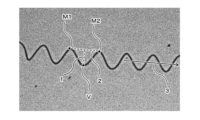
- FIG. 1 is an example of a single fiber constituting the crimped fiber of the present embodiment, and is an observation diagram for explaining the coil diameter in the crimped form.
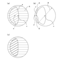
- FIG. 2(a) to FIG. 2(c) are schematic cross-sectional views of the crimped fibers of this embodiment.
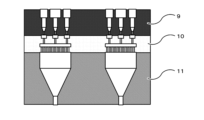
- FIG. 3 is a cross-sectional view for explaining the method for producing crimped fibers according to this embodiment.
- the crimped fiber of the present embodiment is a composite fiber made of two types of polymers, and has excellent hygroscopicity with a moisture absorption/desorption parameter ⁇ MR of 2.0% or more. Therefore, it is possible to obtain a fiber structure excellent in wearing comfort as a cooling material.
- the crimped fiber of the present embodiment has a hygroscopicity parameter ⁇ MR of 2.0% or more, which is an index of hygroscopicity.
- ⁇ MR is the difference in the moisture absorption rate of the fiber between the high temperature and high humidity conditions represented by a temperature of 30° C. and a relative humidity of 90% and the standard temperature and humidity conditions represented by a temperature of 20° C. and a relative humidity of 65%.
- ⁇ MR the more hygroscopic the fiber. If the ⁇ MR of the crimped fibers of the present embodiment is 2.0% or more, the feeling of stuffiness in clothes made of the crimped fibers of the present embodiment is reduced, and the wearing comfort is improved.
- a more preferable range of ⁇ MR is 4.0% or more.
- a more preferable range of ⁇ MR is 6.0% or more, and the amount of moisture that can be retained in the fiber is further increased, so that when it is made into a fabric, it quickly absorbs water vapor, so that a cool contact sensation can be experienced.
- This characteristic is an effective characteristic from the viewpoint of wearing comfort, and if the ⁇ MR, which further enhances the moisture absorption performance, is 8.0% or more, it can suppress stuffiness and stickiness even in a high temperature and high humidity environment in summer. It can be mentioned as a particularly preferable range.
- the level that can be achieved in this embodiment is about 17%, which is the substantial upper limit. That is, ⁇ MR may be 17% or less.
- the crimped fiber of the present embodiment satisfies the above range of ⁇ MR even before and after hot water treatment such as dyeing.
- Hygroscopic fibers incorporate water molecules through physical adsorption and/or the formation of interactions between functional groups in the molecular structure of the components that make up the fibers and water molecules.
- many water molecules are taken into the fiber, resulting in large volume swelling.
- a hygroscopic fiber absorbs moisture and causes volumetric swelling, it is difficult to cause elongation deformation in the direction of the fiber axis. transform.
- fibers composed of a polymer having a rigid aromatic ring in the main skeleton that constitutes the repeating unit, such as aromatic polyester are difficult to deform and cannot disperse the stress generated when the volume swells due to moisture absorption.
- cracks and the like may occur on the fiber surface.
- deformation due to volumetric swelling due to moisture absorption causes polymer-to-polymer separation between the sea and islands or between the sheath and core. peeled off, and voids were generated in the polymer constituting the island portion and the core portion.
- the crimped fiber of the present embodiment which suppresses defects that occur on the fiber surface or inside the fiber due to the volume swelling during moisture absorption, has a coiled crimp configuration in the fiber axis direction.
- the term "coil-shaped crimp" as used herein includes, for example, a three-dimensional spiral crimp developed by bending the single fibers constituting the crimped fiber according to the difference in shrinkage between two types of polymers due to heat treatment. , the shape of the single fiber is similar to that of a coil spring defined in JIS B 0103:2012 (spring terminology).
- the crimped fibers of the present embodiment have a coil spring shape, the single fibers are twisted in the fiber axis direction. Therefore, when the single fiber swells due to moisture absorption, a force acts on the single fiber in the twisting direction based on this twist, and the single fiber can be elongated and deformed in the fiber axis direction. Due to this elongation deformation, expansion deformation in the direction of increasing the area of the cross section of the fiber is reduced, and the durability of the crimped fiber can be further enhanced.
- the crimped fiber when it is made into a fiber structure such as a fabric, the crimped fiber stretches and deforms in the fiber axis direction when absorbing moisture and/or water, so that the breathability of the fabric can be maintained and comfort when worn. do. Furthermore, during moisture release and/or drying, a force acts on the single fiber in the untwisting direction, returning it to the shape it had before it absorbed moisture and/or water. can. In addition, since the crimped fibers can be elongated and deformed in the direction of the fiber axis by an external force, the fiber structure such as the fabric exhibits the stretch performance required to follow the movement of the wearer.
- the crimped fiber of the present embodiment is controlled by the ratio Dc/df between the coil diameter Dc and the single fiber diameter df. is important.
- the flexible coiled crimped form when it is made into a fabric such as a woven fabric or a knitted fabric, it exhibits a function such as moderate stretchability, and a soft texture with a sense of resilience and swelling can be obtained.
- the smaller the Dc/df the harder the coiled crimped shape becomes, and the more difficult it is to be elongated and deformed, but the shape stability of the crimped shape is improved. It can maintain its shape. Furthermore, since the shape of the coiled crimped form is stable, when the fabric is made into a fabric, due to the twist of the crimped fibers, adjacent fibers and the crimped form become entangled, and voids can be expressed between the fibers. .
- a function such as water absorption is exhibited by the capillary action of the fine inter-fiber voids, and combined with the hygroscopicity of the crimped fibers of the present embodiment, a fiber structure excellent in wearing comfort as a cooling material can be obtained.
- the shape of the coiled crimped form is stable, followability to the movements of the wearer is also exhibited.
- the crimped fiber of the present embodiment has a ratio Dc/df of the coil diameter Dc to the single fiber diameter df of 2.0 or more and 20.0 or less.
- Dc/df the ratio of the coil diameter Dc to the single fiber diameter df of 2.0 or more and 20.0 or less.
- Dc/df is preferably 4.0 or more and 18.0 or less, more preferably 6.0 or more and 16.0 or less.
- the coil diameter Dc referred to in the present embodiment means that a single fiber separated from the crimped fiber of the present embodiment is two-dimensionally observed from the side (direction perpendicular to the fiber axis direction), and the fiber It is a numerical value measured from peaks and valleys alternately observed in the width direction 3 .
- the fiber sample to be evaluated is made into a 10 m skein using a measuring machine or the like, immersed in boiling water at 98°C or higher with a load of 0.2 mg/d, and subjected to boiling water treatment for 15 minutes. After the boiling water-treated yarn is sufficiently dried by air drying, a load of 2 mg/d is applied, and after 30 seconds or more, the yarn bundle is marked at an arbitrary point so that the distance between two points is 3 cm.
- the single fiber diameter df referred to in this embodiment is a value calculated by the following method. That is, a fiber sample is embedded in an embedding agent such as an epoxy resin, and a fiber cross section perpendicular to the fiber axis is examined with a scanning electron microscope (for example, a scanning electron microscope (SEM) manufactured by HITACHI) at 10 or more. Images are taken at a magnification that allows observation of single fibers, and the diameter of single fibers randomly extracted within the same image from each taken image (reference numeral 8 in (b) of FIG. 2) is measured in ⁇ m to the second decimal place. Measure up to This operation is performed on 10 randomly selected single fibers, and a simple numerical average is obtained.
- a scanning electron microscope for example, a scanning electron microscope (SEM) manufactured by HITACHI
- the area is measured by analyzing the obtained image, for example, using the computer software WinROOF manufactured by Mitani Shoji, and the same area Adopt a value that can be obtained by converting to a yen with
- the crimped fiber of the present embodiment has a coil pitch number of 1.0 coils/mm or more and 10.0 coils/mm or less in the crimped form having a coil shape in the fiber axis direction.
- the number of coil pitches referred to here is a requirement for determining the amount of extension deformation of the coiled crimped form. That is, by setting the number of coil pitches to 1.0 pieces/mm or more, a sufficient number of coiled crimps exist per unit length, so that the stress generated due to volumetric swelling during moisture absorption can be reduced. The elongational deformation necessary for dispersion can be produced.
- the number of coil pitches is preferably 1.5 coils/mm or more and 9.0 coils/mm or less, more preferably 2.0 coils/mm or more and 8.0 coils/mm or less.
- the number of coil pitches in the crimped fiber of this embodiment is calculated by the following method. Using the image taken when measuring the coil diameter Dc, the distance (mm) (reference numeral 2 in FIG. 1) between arbitrary adjacent peaks M1 and M2 in the coiled crimped form Seek up to 2nd place. This operation is performed at three arbitrary points per single fiber, and this is performed at 10 different single fibers. A reciprocal of a simple number average of these measurement results is obtained, and the value obtained by rounding off to the second decimal place is taken as the number of coil pitches (pieces/mm).
- the crimped fiber of this embodiment has a fiber cross section composed of two types of polymers.
- the polymer referred to here is preferably a fiber-forming thermoplastic polymer.
- the crimped fibers of the present embodiment have excellent hygroscopicity, they can be used as innerwear fibers that are close to the wearer's skin, for example, in clothing applications. In the case of innerwear, other clothing made of other materials may be worn over it. When layered in this manner, friction between the innerwear and other clothing can generate static electricity, which can compromise the wearer's comfort. Therefore, the crimped fiber of the present embodiment has a half-life at a temperature of 20 ° C. and a relative humidity of 40% measured according to JIS L1094 (testing method for electrification of woven and knitted fabrics, 2014) A method (half-life measurement method). It is preferably 10 seconds or less.
- the half-life is the time it takes for the charged voltage to decrease to 50% of the initial charged voltage after applying a specific voltage to the fabric sample. is an indicator of
- the half-life at a temperature of 20° C. and a relative humidity of 40% is 10 seconds or less, the antistatic property of the crimped fiber of the present embodiment is good, and static electricity generated by friction when layered is easily released. , the clothes made of the crimped fibers of the present embodiment can be worn comfortably.
- the half-life at a temperature of 20° C. and a relative humidity of 40% is more preferably 5 seconds or less.
- the crimped fiber of the present embodiment has a composite form in which two types of polymers, polymer A and polymer B, are bonded in the cross section of the fiber, and the polymer A is completely covered with the polymer B. is important.
- the expression that the polymer A is completely covered with the polymer B means that the polymer A is not exposed on the fiber surface layer of the crimped fiber and the polymer B is continuously formed in the cross section of the fiber. do.
- FIG. 2(a) shows an example of a fiber cross section of the crimped fiber of this embodiment.
- polymer component 5 indicated by horizontal hunting is polymer B
- polymer component 4 indicated by 30-degree hunting (slanting lines rising to the right) is polymer A.
- the polymer A is completely covered with the polymer B and is not exposed on the fiber surface layer of the crimped fiber.
- the durability at the interface between the two polymers can be enhanced even if the fibers are deformed due to volume swelling during moisture absorption.
- Suitable polymers for achieving the object of the present embodiment include aromatic polyesters such as polyethylene terephthalate, polytrimethylene terephthalate, and polybutylene terephthalate; aliphatic polyesters such as polylactic acid; Aliphatic polyamides typified by methylene adipamide and the like, semi-aromatic polyamides typified by polyhexamethylene terephthalamide, thermoplastic elastomers typified by thermoplastic polyurethanes, polyolefins typified by polypropylene, and the like can be mentioned.
- aromatic polyesters or aliphatic polyamides are preferably used from the viewpoints of mechanical properties, heat resistance, and handleability during production.
- the above aromatic polyester is a repeating unit linked via an ester bond to a main chain composed of a combination of an aromatic dicarboxylic acid and an aliphatic diol, an aliphatic dicarboxylic acid and an aromatic diol, or an aromatic dicarboxylic acid and an aromatic diol. It is a high molecular weight body having Among these, aromatic polyesters composed of aromatic dicarboxylic acids and aliphatic diols are preferred.
- aromatic dicarboxylic acids examples include terephthalic acid, isophthalic acid, phthalic acid, 5-sodiumsulfoisophthalic acid, 5-(tetraalkyl)phosphoniumsulfoisophthalic acid, 4,4′-diphenyldicarboxylic acid, and 2,6-naphthalenedicarboxylic acid. etc., but not limited to these.
- aliphatic diols include, but are not limited to, ethylene glycol, 1,3-propanediol, 1,4-butanediol, hexanediol, cyclohexanediol, diethylene glycol, hexamethylene glycol, neopentyl glycol, and the like.
- the crimped fiber can maintain its crimped shape even if the crimped fiber is repeatedly stretched and deformed by moisture absorption and desorption because the rigidity of the fiber increases. .
- a texture having firmness and stiffness can be obtained.
- aromatic polyesters generally do not have functional groups that form strong interactions with water molecules in the polymer structure, crimped fibers and fabrics with excellent quick-drying properties can be obtained.
- the above aliphatic polyamide is a high molecular weight body having repeating units in which a so-called hydrocarbon group is linked to the main chain via an amide bond.
- it is synthesized by polycondensation reaction using aminocarboxylic acid and cyclic amide as starting materials, or polycondensation reaction using dicarboxylic acid and diamine as starting materials.
- polyamides include, but are not limited to, polycapramide, polyundecanolactam, polylauryllactam, polyhexamethylene adipamide, polyhexamethylene sebacamide, polyhexamethylene dodecane diamide, and the like.
- aliphatic polyamide When aliphatic polyamide is used in the crimped fiber of the present embodiment, the amide bond in the repeating unit and the amino group bonded to the end of the polymer structure have hygroscopicity, so the crimped fiber has extremely high hygroscopicity. is obtained.
- aliphatic polyamide has a low glass transition point, which is a polymer characteristic, and is highly flexible, so that the crimped fiber is easily deformed by elongation due to moisture absorption and / or water absorption, and the crimped fiber of the present embodiment is durable. The effect of increasing the sexuality is likely to be exhibited. Furthermore, even when it is made into a cloth, it has a very high hygroscopicity, so a cool contact feeling can be obtained. In addition, a low glass transition point provides a soft texture.
- the method for producing the polymer in the present embodiment is not limited, and if the raw materials at the time of production are included in the monomer, the monomer may be synthesized and produced by general polycondensation reaction, addition polymerization reaction, etc. .
- Monomers are not limited to petroleum-derived monomers, biomass-derived monomers, mixtures of petroleum-derived monomers and biomass-derived monomers, recycled monomers obtained by recycling polymers by chemical recycling, and the like.
- a polymer may be produced from waste such as waste plastic by a material recycling technique.
- the polymer in the present embodiment may be copolymerized or mixed with a second component and a third component in addition to the main component within a range not departing from the purpose of the present invention.
- the crimped fiber of the present embodiment has a moisture absorption/desorption parameter ⁇ MR, which is an index of moisture absorption, of 2.0% or more.
- ⁇ MR moisture absorption/desorption parameter
- methods for adjusting the ⁇ MR of the crimped fiber of the present embodiment within the above range include adding a hygroscopic compound and disposing a polymer having high hygroscopicity (hereinafter sometimes referred to as a hygroscopic polymer). and treating the polymer molecules on the surface of the fiber with ozone or the like to generate hygroscopic functional groups.
- hygroscopic polymers are preferably used in order to obtain crimped fibers having excellent hygroscopicity.
- suitable hygroscopic polymers used in the crimped fibers of the present embodiment include polyetheresters, polyetheramides, polyetheresteramides, polyamides, thermoplastic cellulose derivatives, polyvinylpyrrolidone, and the like.
- polyether esters, polyether amides, and polyether ester amides containing polyether as a copolymer component are preferable because they have excellent stability during melt molding and high hygroscopicity, which is the desired property.
- Polyetherester is a block copolymer that has an ester bond and an ether bond in the polymer structure. Specifically, it is a block copolymer obtained by a polycondensation reaction of a polyester-forming component composed of a dicarboxylic acid and a diol and a polyalkylene glycol component.
- the combination of the polyester-forming component and the polyalkylene glycol component is not limited, but as a preferred example, from the viewpoint of the heat resistance of the hygroscopic polymer, an aromatic polyester composed of an aromatic dicarboxylic acid and an aliphatic diol is used as the polyester-forming component. and polyether esters obtained by copolymerizing polyethylene glycol. Polyether esters composed of polybutylene terephthalate and polyethylene glycol, which are excellent in crystallinity, are more preferable because they can suppress elution of the hygroscopic polymer into hot water.
- polyetheramide is a block copolymer that has amide bonds and ether bonds in the polymer structure. Specifically, it is a block copolymer obtained by polycondensation reaction of one or more polyamide-forming components selected from lactams, aminocarboxylic acids, diamines and salts of dicarboxylic acids, and polyalkylene glycol components. .
- polyamide-forming component includes lactams such as ⁇ -caprolactam, ⁇ -aminocarboxylic acids such as aminocaproic acid, and polyhexamethylene adipate.
- polyethylene glycol components include nylon salts of diamine-dicarboxylic acids that are precursors of polyhexamethylene sebacamide and the like, and polyalkylene glycol components include polyethylene glycol.
- polyether amide obtained by using ⁇ -caprolactam as a polyamide-forming component and copolymerizing polyethylene glycol is more preferable.
- polyether ester amide is a block copolymer with ether bonds, ester bonds and amide bonds in the polymer structure.
- one or more polyamide-forming components selected from lactams, aminocarboxylic acids, salts of diamines and dicarboxylic acids, and a polyether ester component composed of a dicarboxylic acid and a polyalkylene oxide glycol are subjected to a polycondensation reaction. The resulting block copolymer polymer.
- polyamide-forming component includes those exemplified in the above polyetheramide.
- Polyalkylene glycol component constituting the polyether ester component includes polyethylene glycol from the viewpoint of hygroscopicity, and dicarboxylic acid includes adipic acid, sebacic acid, dodecadiic acid, terephthalic acid, and isophthalic acid.
- the hygroscopic polymer in the crimped fiber of the present embodiment may be copolymerized or mixed with a second component and a third component within the scope of the purpose of the present invention. is preferably 10 mol % or less as a monomer amount of the copolymerization component with respect to the total amount of monomers.
- the above-mentioned hygroscopic polymers have a high affinity for water and are easily eluted when they come into contact with water or hot water during dyeing.
- the hygroscopicity of the fiber may decrease. Therefore, in the crimped fiber of the present embodiment, the hygroscopic polymer as described above is completely covered with the polymer B exposed on the fiber surface layer in the cross section of the fiber, that is, the hygroscopic polymer as the polymer A is preferably placed.
- the crimped fibers of the present embodiment exhibit a remarkable effect of increasing the durability of the crimped fibers due to the coil-like crimped shape that the crimped fibers have in the fiber axis direction, and the crimped fibers having excellent hygroscopicity can be obtained.
- the combination of two types of polymers that constitute the crimped fiber of the present embodiment is not particularly limited, but is preferably selected from combinations of polymers that have a high affinity between the two types of polymers and are easily compatible.
- polymers with high affinity By combining polymers with high affinity, entanglement of molecular chains at the polymer interface is promoted, and interfacial peeling of two types of polymers can be suppressed.
- followability of the fibers when deformed is improved, and the durability of the crimped fibers can be further enhanced without accumulating deformation strain on the surface of the fibers or inside the fibers.
- the two polymers each have the same type of bond in the main skeleton constituting the repeating unit.
- the bond here include an amide bond, an ester bond, an ether bond, a urea bond, and a urethane bond. That is, having the same type of bond in the main skeleton constituting the repeating unit of each of the two polymers means, for example, when the repeating unit of polymer A has an amide bond, the repeating unit of polymer B also has an amide bond. means having a bond. Similarly, when the repeating unit of polymer A has an ester bond, it means that the repeating unit of polymer B also has an ester bond.
- a polyether ester as the hygroscopic polymer if the polymer A or polymer B is an aromatic polyester. Also, if the polymer A or polymer B is an aliphatic polyamide, it is preferable to use polyetheramide or polyetheresteramide as the hygroscopic polymer. By combining these, the affinity between the two polymers is high, and the durability at the interface between the two polymers can be enhanced.
- the stress generated due to the volumetric swelling of the fiber when absorbing moisture can be dispersed by elongation of the crimp applied to the composite fiber, and the deformation strain is not accumulated on the fiber surface or inside the crimped fiber. durability can be further enhanced.
- the combination of polymers with high affinity as used herein can also be selected based on, for example, the solubility parameters (SP values) of two types of polymers.
- SP value is a parameter that reflects the cohesive force of a substance defined by (evaporation energy/molar volume) 1/2 , and the closer this value is, the higher the affinity of the polymer combination. .
- This SP value is known for various polymers, and is described, for example, in "Plastic Data Book” (Asahi Kasei Amidas Co., Ltd./Plastic Editorial Department, 1999), page 189, and the like.
- the two polymers have good adhesive strength.
- the absolute value of the difference between the SP values of the two selected polymers is preferably 3 (MJ/m 3 ) 1/2 or less, more preferably 2 (MJ/m 3 ) 1/2 or less.
- a preferred example of a combination of the above polymers for achieving the object of the present invention is polyethylene terephthalate and polyether ester (a copolymer of polyethylene terephthalate and polyethylene glycol) if polymer A or polymer B is an aromatic polyester. ), polyethylene terephthalate and polyether ester (copolymer of polybutylene terephthalate and polyethylene glycol), polybutylene terephthalate and polyether ester (copolymer of polybutylene terephthalate and polyethylene glycol), and the like.
- the polymer A is a polyetherester (a copolymer of polybutylene terephthalate and polyethylene glycol) and the polymer B is a polybutylene terephthalate is preferable.
- the polymer B is polybutylene terephthalate, which is flexible and easily deformable, even if the fiber swells in volume when absorbing moisture, the deformation of the polymer B is combined with the effect of dispersing the stress due to the crimped shape, and the fiber of the crimped fiber The durability of the surface layer can be further enhanced.
- both polymer A and polymer B have a polybutylene terephthalate structure, deformation strain does not accumulate at the contact interface between polymer A and polymer B, and the durability of the crimped fiber can be further enhanced. .
- polymer A or polymer B is an aliphatic polyamide
- suitable combinations when polymer A or polymer B is an aliphatic polyamide include polycapramide and polyetheresteramide (a copolymer of polycapramide and polyethylene glycol with adipic acid bound to the end), polycapramide and poly ether ester amide (copolymer of polycapramide and polyethylene glycol with terephthalic acid bound at the end), polyhexamethylene adipamide and polyether ester amide (copolymer of polycapramide and polyethylene glycol with terephthalic acid at the end), Examples include polyhexamethylene sebacamide and polyether ester amide (copolymer of polycapramide and polyethylene glycol with terephthalic acid bound to the end), and polycapramide added with polycapramide and polyvinylpyrrolidone.
- the polymer A is a polyether ester amide (a copolymer of polycapramide and polyethylene glycol with terephthalic acid bound to the terminal) and the polymer B is a polycapramide is preferred.
- the polymer B is a hygroscopic polycapramide
- a crimped fiber having both excellent hygroscopic performance and mechanical properties can be obtained.
- polycapramide is also a flexible and easily deformable polymer, even if the fiber swells in volume when it absorbs moisture, the deformation of polymer B combined with the effect of dispersing the stress due to the crimped shape will increase the durability of the surface layer of the crimped fiber. can be enhanced.
- both the polymer A and the polymer B have a polycapramide structure, the durability at the contact interface between the polymer A and the polymer B can be further enhanced.
- the crimped fiber of the present embodiment is composed of aliphatic polyamide, it is highly flexible due to the low glass transition point, which is a polymer characteristic of aliphatic polyamide, so that it is particularly easy to deform, and the amount of deformation is large. Become.
- the crimped fibers are repeatedly elongated and deformed due to moisture absorption and/or water absorption, or when the crimped fibers are deformed by an external force, it is preferable to increase the durability of the crimped fibers.
- the crimped fiber of the present embodiment is composed of an aliphatic polyamide, particularly when the polymer B is an aliphatic polyamide, the ⁇ -type crystal orientation parameter of the polyamide as the polymer B is 1.7 or more. It is preferably 2.6 or less.
- the ⁇ -type crystal of polyamide is a stable crystal type that is formed when high stress is applied.
- the ⁇ -type crystal orientation parameter of the polyamide that is the polymer B is 1.7 or more, the crystallization of the polyamide is advanced and the durability of the crimped fiber is excellent. Even when the crimped fibers are deformed by elongation or are deformed by an external force, they exhibit excellent durability.
- the ⁇ -type crystal orientation parameter of the polyamide is 2.6 or less, the crystallization of the polyamide does not proceed excessively, so that the coiled crimped shape becomes flexible and the elongation deformation becomes easy. In addition, since water molecules can permeate the fiber, it has excellent hygroscopicity.
- the polymer B is an aliphatic polyamide
- the ⁇ -type crystal orientation parameter of the polyamide as the polymer B is more preferably 1.8 or more and 2.5 or less.
- the composite form of the two types of polymers in the fiber cross section of the crimped fiber of this embodiment is not particularly limited except that the polymer A is completely covered with the polymer B.
- the position of the center of gravity of the polymer A referred to here is the point a in FIG. 2(a), and the center of the fiber cross section is the point c in FIG. 2(a).
- the center of gravity a of the polymer A and the center c of the cross section of the fiber are separated, so that the fiber has a three-dimensional spiral structure and is crimped in a coil shape in the fiber axis direction.
- the morphology can be expressed well.
- the composite form of the crimped fiber of the present embodiment is an eccentric core-sheath cross section, it is preferable to satisfy both of the following requirements.
- the ratio S/df between the minimum thickness S of the polymer B covering the polymer A and the single fiber diameter df is 0.01 or more and 0.10 or less.
- the peripheral length of the portion having a thickness within 1.05 times the minimum thickness S is 30% or more of the circumference of the fiber cross section (hereinafter sometimes referred to as S ratio).
- the minimum thickness S of the polymer B covering the polymer A is obtained as follows. That is, the crimped fiber of the present embodiment is embedded in an embedding agent such as an epoxy resin as it is as a yarn bundle, and the cross section of this fiber is measured with a transmission electron microscope (TEM) at a magnification that allows observation of 10 or more fibers. Take an image. At this time, if metal dyeing is applied, the contrast between the polymer A and the polymer B can be clarified by utilizing the dyeing difference between the polymers. Randomly extract one single fiber from the photographed image, select an arbitrary point E on the interface between polymer A and polymer B as shown in FIG. pull.
- TEM transmission electron microscope
- a perpendicular line is drawn from the point E to the tangent line toward the fiber surface, and the intersection point F with the fiber surface is obtained.
- the length of the line segment EF is measured to the third decimal place, and the minimum value of the length of the line segment EF is defined as the thickness ( ⁇ m) (reference numeral 7 in FIG. 2).
- the single fiber diameter df ( ⁇ m) is measured by the above method. Using the obtained S and df, S/df was calculated by rounding to the third decimal place.
- the composite form has an eccentric core-sheath cross section that satisfies the above requirements, the distance between the center of gravity a of the polymer A and the center c of the fiber cross section can be freely set, and a good coil in the fiber axis direction can be obtained.
- a crimped morphology can be developed. As a result, sufficient elongation deformation of the crimp can be generated to disperse the stress that occurs due to volumetric swelling during moisture absorption.
- the coil-like crimped form when it is made into a fiber structure such as a fabric, it exhibits functionality such as water absorption and moderate stretchability, making it a material excellent in wearing comfort.
- the cross-sectional shape of the crimped fiber of the present embodiment is not limited to a circular cross-section, and various cross-sectional shapes such as flat, Y-shaped, T-shaped, hollow-shaped, field-shaped, and I-shaped can be adopted.
- the crimped fibers of this embodiment may be in any form such as long fibers (filaments) and short fibers (staples).
- filament it may be a monofilament consisting of one single yarn or a multifilament consisting of a plurality of single yarns.
- short fibers there are no restrictions on the cut length and the number of crimps.
- the fineness of the crimped fibers of the present embodiment may be appropriately set according to the application, but in the case of long fibers for clothing, 8 dtex or more and 150 dtex or less are practically preferable.
- the strength is 1.5 cN/dtex or more for clothing, but even if it is 1.5 cN/dtex or less, there is a problem by taking measures such as using it in combination with other fibers when fabricating. can be used without
- the elongation may be appropriately set according to the application, but from the viewpoint of workability when processing into a fabric, it is preferably 25% or more and 60% or less.
- the crimped fibers of the present embodiment preferably have a single fiber fineness of 8.0 dtex or less.
- the single fiber fineness is more preferably 5.0 dtex or less, still more preferably 3.0 dtex or less.
- the crimped fibers of the present embodiment are made of aromatic polyester, the rigidity of the fibers increases due to the molecular structure, so the crimped form can be maintained.
- the crimp becomes hard and the crimped fiber is elongated due to moisture absorption and/or water absorption, or when an external force is applied, the crimped fiber is elastically deformed, and this repeated deformation occurs. It is preferable to increase the durability of
- the crimped fiber of the present embodiment preferably has an initial tensile resistance of 10 cN/dtex or more and 100 cN/dtex or less if the polymer A or polymer B is an aromatic polyester.
- the initial tensile resistance is measured by the method described in Section 8.10 of the chemical fiber filament yarn test method (JIS L1013 (2010)), and is correlated with the apparent Young's modulus. It indicates ease.
- the coiled crimp shape is rigid, so that the crimp does not weaken even when elongated and deformed, and after elongated deformation due to moisture absorption and / or water absorption. , releasing moisture and/or drying to return to the original crimped form.
- the initial tensile resistance is 100 cN/dtex or less, the hardness of the coiled crimp can be reduced, and the stress generated by volumetric swelling during moisture absorption can be dispersed by elongation of the crimp. Deformation strain does not accumulate on the fiber surface or inside the fiber, and excellent quality can be obtained when a woven or knitted fabric is formed.
- the crimped fibers of the present embodiment can be obtained by known melt spinning and composite spinning methods, and examples thereof are as follows. However, the spinning method and composite method are not limited to those exemplified here.
- Methods for producing the crimped fibers of the present embodiment composed of two types of polymers include a melt spinning method for the purpose of producing long fibers, a solution spinning method such as a wet and dry-wet method, and a sheet-like fiber structure.
- the meltblowing method and the spunbonding method suitable for this are mentioned.
- the melt spinning method is preferable from the viewpoint of increasing productivity.
- the spinning temperature at that time is a temperature at which mainly high-melting-point or high-viscosity polymers exhibit fluidity among the types of polymers used.
- the temperature at which this fluidity is exhibited varies depending on the molecular weight, it is preferable to set the temperature between the melting point of the polymer and the melting point +60° C., since stable production can be achieved.
- melt spinning method for example, polymer A and polymer B are separately melted, weighed and transported by a gear pump, and a composite flow is formed by a known method so as to have a specific composite structure, and a spinneret is formed.
- Dispense from Cooling air is blown against the discharged yarn by a yarn cooling device such as a chimney to cool it to room temperature, and the yarn is fed with oil by an oiling device and converged.
- the bundled yarn is entangled with a fluid entanglement nozzle device and passed through a take-up roller and a drawing roller. At this time, the film is drawn according to the ratio of the peripheral speeds of the take-up roller and the drawing roller.
- a method of heat-setting a yarn with a drawing roller and winding it up with a winder can be used.
- a two-step method in which the peripheral speeds of the take-up roller and the drawing roller are set to the same speed, and the undrawn yarn is obtained by winding the yarn with a winder having the same speed, and drawing is performed in a separate step.
- the melt viscosity ratio of the two polymers (polymer with high melt viscosity/polymer with low melt viscosity) to less than 5.0, a composite polymer flow can be stably formed, It is preferable because it can obtain a fiber with a good composite cross section.
- a combination of polymers that cause a difference in shrinkage during heat treatment is preferred, and the difference in melt viscosity between the two polymers to be combined is preferably 10 Pa ⁇ s or more.
- the composite spinneret used when producing the crimped fiber of the present embodiment it is preferable to use the composite spinneret described in Japanese Patent Application Laid-Open No. 2011-208313.
- the composite spinneret shown in FIG. 3 is assembled into a spinning pack in a state in which roughly three types of members, namely a weighing plate 9, a distribution plate 10 and a discharge plate 11, are layered from above, and subjected to spinning.
- a conventional composite spinneret it is difficult to control the composite cross-sectional shape as described above, and it is preferable to use a composite spinneret utilizing fine flow channels as illustrated in FIG.
- the metering plate 9 meters and flows the amount of polymer per each discharge hole and each distribution hole, and the distribution plate 10 controls the composite cross section in the cross section of the single fiber and its cross-sectional shape, Discharge plate 11 serves to compress and discharge the composite polymer stream formed by distribution plate 10 .
- the members stacked above the weighing plate 9 can be members having channels formed in accordance with the spinning machine and the spinning pack. .
- the existing spinning pack and its members can be used as they are, so there is no need to specialize the spinning machine especially for the spinneret.
- a plurality of flow path plates may be stacked between the flow path and the measuring plate 9 or between the measuring plate 9 and the distribution plate 10.
- the composite polymer stream discharged from the discharge plate 11 is cooled and solidified in accordance with the manufacturing method described above, then oiled, and taken up by rollers at a specified peripheral speed to obtain fibers having a desired composite cross section.
- the composite form of the crimped fiber of the present embodiment is an eccentric core-sheath cross section, it is particularly preferable to use the composite spinneret described above from the viewpoint of stable cross section formation.
- the composite ratio of polymer A and polymer B is preferably from 70/30 to 20/80 in terms of polymer A mass/polymer B mass ratio.
- a difference in orientation occurs between the two polymers in the spinning process and the drawing process, resulting in a difference in shrinkage during heat treatment, so that fibers with excellent crimp properties can be obtained.
- ⁇ MR and antistatic property can be controlled within a specific range for the crimped fiber of the present embodiment.
- the ratio of polymer A mass/polymer B mass is more preferably 60/40 to 30/70
- the spinning draft represented by the speed ratio between the spinneret discharge linear speed and the take-up roller is preferably 10 or more and less than 300.
- the spinneret ejection linear velocity referred to here is obtained by dividing the ejection volume per unit time of the polymer ejected from the holes of the ejection plate 11 of the composite spinneret by the cross-sectional area of the ejection hole of the nozzle.
- This spinning draft correlates with the orientation of the fibers that occur during the period from being discharged through the holes of the discharge plate 11 of the composite spinneret to being cooled and taken up by the take-up roller.
- the orientation of the fibers up to becomes large.
- the orientation difference occurs between the two types of polymers, which causes a difference in shrinkage during heat treatment. Fibers with crimping properties can be obtained.
- the spinning draft is less than 300, the tension applied to the polymer immediately after ejection from the composite spinneret can be reduced, and yarn breakage due to excessive tension until the polymer is taken up by the take-up roller can be suppressed. Further, when the spinning draft is 10 or more, sufficient orientation of the fibers is obtained, the difference in orientation tends to occur between the two types of polymers, and the difference in shrinkage during heat treatment tends to occur, resulting in improved crimp properties.
- the spin draft is more preferably 30 or more and less than 150.
- the crimped fiber of the present embodiment when heat setting is performed on rollers after drawing, it is preferable to perform the heat treatment in a tensioned state, and then cool the fiber to a temperature below the glass transition point while maintaining the tension.
- the polymer molecular chain structure of the fiber is fixed by tension heat treatment and tension cooling treatment, the contraction stress can be increased. It is effective to control within a specific range in the crimped fibers of the embodiment.
- the crimped fiber of the present embodiment not only expresses crimps by utilizing the heat shrinkage difference of the polymer as described above, but also expresses crimps by applying post-processing such as false twisting and twisting. good too. More preferably, it has both crimped structures. This is because, in addition to the crimp due to the difference in heat shrinkage of the polymer, by applying twisting processing, two types of crimped forms are mixed, so the ratio Dc/df between the coil diameter Dc and the single fiber diameter df The coil pitch number can be controlled within a specific range for the crimped fibers of this embodiment.
- the method of false twisting is not particularly limited as long as it is a method commonly used for polyamides, polyesters, etc., but considering productivity, friction false twisting using a disc or belt It is preferable to process using a machine.
- T is the number of false twists indicating the number of twists (turns/m) in the twisted region
- Fi is the total fineness (dtex) of the textured yarn after the false twisting process.
- the false twist number T is measured by the following method. The textured yarn running in the twisting area of the false twisting step is collected with a length of 50 cm or more so as not to untwist just before the twister. The false twist number T is obtained by attaching the collected yarn sample to a twist tester and measuring the number of twists by the method described in JIS L1013 (2010) 8.13.
- the crimp configuration can be controlled, and deterioration of the quality of the fabric such as crimps and streaks can be suppressed, and the intended effect of the present invention can be exhibited.
- the fiber structure composed of crimped fibers and/or post-processed yarns of the present embodiment may be of any woven or knitted structure, such as plain weave, twill weave, satin weave, or variations thereof, warp knitting, weft knitting. , circular knitting, lace knitting, or variations of these knittings can be preferably employed.
- the crimped fibers of the present embodiment may be combined with other fibers by union weaving or union knitting when forming a fiber structure, or may be formed into a fiber structure after being mixed with other fibers.
- the fiber structure composed of crimped fibers and/or post-processed yarns of the present embodiment has excellent hygroscopicity, so it can be suitably used in applications where comfort and quality are required. Examples include, but are not limited to, general clothing applications, sports clothing applications, bedding applications, interior applications, material applications, and the like.
- ⁇ 1> Composite fiber composed of two kinds of polymers, polymer A and polymer B, having a coiled crimped shape in the fiber axis direction, and having a ratio Dc/df of the coil diameter Dc to the single fiber diameter df of 2.0. 0 or more and 20.0 or less, the number of coil pitches is 1.0 pieces / mm or more and 10.0 pieces / mm or less, the polymer A is completely covered with the polymer B in the fiber cross section, and the moisture absorption and desorption parameter ⁇ MR is 2.0% or more.
- ⁇ 2> The crimped fiber according to ⁇ 1>, wherein the highly hygroscopic polymer of the two types of polymer is polymer A.
- ⁇ 3> The crimped fiber according to ⁇ 1> or ⁇ 2>, wherein the two polymers have the same type of bond in the main skeleton constituting the repeating unit of each of the two polymers.
- ⁇ 4> A textile product using the crimped fiber according to any one of ⁇ 1> to ⁇ 3>.
- a polymer sample with a moisture content of 300 ppm or less by a vacuum dryer is placed in a heating furnace set to the same temperature as the spinning temperature using a Toyo Seiki capilograph, and melted in a nitrogen atmosphere. , the viscosity was measured by extruding the sample from the capillary at the tip of the heating furnace while changing the strain rate stepwise. The measurement was started after the sample was placed in the heating furnace and allowed to stay there for 5 minutes.
- Tm Melting point of polymer (Tm) Using a differential scanning calorimeter (DSC) Q2000 manufactured by TA Instruments, 20 mg of a polymer sample was heated from 20° C. to 280° C. at a heating rate of 20° C./min, held at 280° C. for 5 minutes, and then cooled. Endothermic observed when the temperature is lowered from 280°C to 20°C at a rate of 20°C/min, held at 20°C for 1 minute, and then further heated from 20°C to 280°C at a rate of temperature increase of 20°C/min. The peak top temperature of the peak was taken as the melting point. When multiple endothermic peaks were observed, the endothermic peak top on the highest temperature side was taken as the melting point.
- DSC differential scanning calorimeter
- Fineness A fiber sample was wound 200 times with a scale measuring machine with a frame circumference of 1.125 m to make a skein, dried with a hot air dryer (105 ⁇ 2 ° C. x 60 minutes), and then the mass of the skein was weighed with a balance. , the fineness was calculated from the value obtained by multiplying the official moisture content. The measurement was performed 4 times, and the average value was used as the fineness.
- MR 1 [(w 65% -w 0 )/w 0 ] ⁇ 100
- MR 2 [(w 90% -w 0 )/w 0 ] ⁇ 100
- ⁇ MR MR 2 -MR 1 (3) At this time, ⁇ MR was calculated by the formulas (1) to (3).
- a tubular knitted fabric was produced by adjusting the fiber sample to a density of 50 using a circular knitting machine NCR-BL manufactured by Eiko Sangyo Co., Ltd. (bottle diameter 3.5 inches (8.9 cm), 27 gauge). When the net fineness of the fibers was less than 80 dtex, the fibers were appropriately combined so that the total fineness of the fibers supplied to the tubular knitting machine was 80 to 160 dtex. When the total fineness exceeded 80 dtex, one yarn was fed to the tubular knitting machine.
- the obtained tubular knitted fabric is put into an aqueous solution containing 1 g/L of sodium carbonate and the surfactant Sunmol BK-80 manufactured by Nicca Chemical, and the aqueous solution is heated to 80° C. and treated for 20 minutes, It was dried in a hot air dryer at 60°C for 60 minutes. Further, the dried tubular knitted fabric was subjected to hot water treatment in water of 100 times the mass of tubular knitted fabric at a treatment temperature of 130°C for a treatment time of 60 minutes, and then dried in a hot air dryer at 60°C for 60 minutes. Thus, a tubular knitted fabric after the hot water treatment was obtained.
- ⁇ MR was calculated according to the description in Section E for the obtained tubular knitted fabric after the hot water treatment.
- Coil diameter Dc A fiber sample was made into a 10 m skein using a measuring machine or the like, immersed in boiling water at 98° C. or higher under a load of 0.2 mg/d, and subjected to boiling water treatment for 15 minutes. After the boiling water-treated yarn was sufficiently dried by air drying, a load of 2 mg/d was applied for 30 seconds or longer, and an arbitrary point on the yarn bundle was marked so that the distance between two points was 3 cm. After that, single fibers are separated from the yarn bundle so as not to be plastically deformed, adjusted so that the distance between the markings made in advance is 3 cm from the original, and fixed on a slide glass.
- the fiber cross section perpendicular to the fiber axis is not a perfect circle
- the area is measured by analyzing the obtained image using the computer software WinROOF manufactured by Mitani Corporation, and a circle having the same area is obtained. A value that can be obtained by conversion was adopted.
- An image for measurement may be taken using a transmission electron microscope (TEM).
- Coil pitch number Using the image taken when measuring the coil diameter Dc in the G term, the distance (mm) between any adjacent peaks M1 and M2 of the crimped coil is measured to the second decimal place.
- the coil pitch is obtained by taking the reciprocal of the simple number average of the results obtained by measuring the desired 3 points per single fiber and performing this on 10 different single fibers, and rounding off to the second decimal place. It was set as the number (pieces/mm).
- J. Stretching Elongation Rate A fiber sample is made into a skein with 10 turns using a measuring machine with an appropriate tension adjusting device.
- the treatment temperature was selected according to JIS L1013 (2010) Section 6, and the wet heat treatment was performed with a load of 0.2 mg/d. Thereafter, treatment was performed according to JIS L1013 (2010) Section 8.11 C method (convenient method) to determine the stretching and elongation rate.
- the number of defects on the fiber surface and inside the fiber The tubular knitted fabric produced by the method described in F and subjected to hot water treatment was vapor-deposited with a platinum-palladium alloy, and a scanning electron microscope (SEM) S-manufactured by Hitachi. Observation was made at 1000 times using a model 4000, and micrographs of 10 fields of view were taken at random. In the obtained photographs of 10 fields of view, the surface of the fibers constituting the tubular knitted fabric was observed, and the number of cracks was counted. In addition, five fibers were randomly extracted from the tubular knitted fabric after the hot water treatment, and an image was taken of each fiber sample at a magnification at which all the single fibers could be observed. The number of voids inside the fiber was counted for single fibers randomly sampled within the same image from each photographed image. The sum of the number of cracks on the surface of the fiber and the number of voids inside the fiber was taken as the number of defects.
- ⁇ -type crystal orientation parameter A fiber sample is measured by laser Raman spectroscopy, and the intensity ratio ((I1120) parallel) of the Raman band derived from the polyamide ⁇ -type crystal observed near 1120 cm ⁇ 1 in parallel polarized light and the perpendicular The ratio of the intensity ratio ((I1120) vertical) in polarized light was used as a parameter for evaluating the degree of orientation. Also, the scattering intensity for each polarization condition (parallel/perpendicular) was normalized based on the Raman band intensity of the CH bending band (near 1440 cm ⁇ 1 ), which is less anisotropic with respect to orientation.
- ⁇ -type crystal orientation parameter (I1120/I1440) parallel/(I1120/I1440) perpendicular.
- the sample for orientation measurement was sectioned with a microtome after being embedded in a resin (bisphenol-based epoxy resin, cured for 24 hours). The section thickness was 2.0 ⁇ m.
- the section sample was cut with a slight inclination from the fiber axis so that the cut surface was elliptical, and the thickness of the short axis of the ellipse was selected and measured at a constant thickness.
- the measurement is performed in a microscopic mode, and the laser spot diameter at the sample position is 1 ⁇ m.
- the orientation of the core and the center of the sheath layer was analyzed, and the orientation was measured under polarized light conditions.
- the degree of orientation was evaluated from the ratio of the Raman band intensities obtained under the parallel condition when the polarization direction coincided with the fiber axis and the perpendicular condition when the polarization direction was perpendicular to the fiber axis.
- Laser Raman spectroscopy device T-64000 (Joobin Yvon/Atago Bussan) Conditions: Measurement mode; Microscopic Raman objective lens; ⁇ 100 Beam diameter; 1 ⁇ m Light source; Ar + laser/514.5 nm Laser power; 50mW Diffraction grating; Single 600gr/mm Slit; 100 ⁇ m Detector; CCD/Jobin Yvon 1024 ⁇ 256.
- a tubular knitted fabric was produced by the method described in Item F. Next, the obtained tubular knitted fabric is put into an aqueous solution containing 1 g/L of sodium carbonate and the surfactant Sunmol BK-80 manufactured by Nicca Chemical. It was dried in a hot air dryer at °C for 60 minutes. Next, dry heat setting is performed at 160 ° C. for 2 minutes, and the tubular knitted fabric after dry heat setting is added with dyes and auxiliaries according to the type of fiber constituting the tubular knitted fabric, and is 100 times the tubular knitted mass. and dyed by setting the dyeing temperature and dyeing time according to the type of fiber.
- L value is measured three times per sample. was measured, and the average value was rounded off to the second decimal place to obtain the L value of the sample. This operation was performed on 10 randomly selected samples, and the fluctuation rate was obtained from the average value and standard deviation of the L values of the 10 samples. When the fluctuation rate of the L value of these 10 samples was 5.0% or less, it was judged that there was no dyeing unevenness.
- n minutes represents an arbitrary time during which the mass of the sample was measured, and represents time intervals of 5 minutes, 10 minutes, and 15 minutes.
- Moisture retention rate WR at an arbitrary time was calculated by Equation (5).
- WR [(w 0 min -w n min )/(w 0 min -w a )] ⁇ 100 (5) If the residual moisture ratio WR calculated by the formula (5) was less than 30% for 75 minutes or less, the drying property was judged to be good, and if it was 60 minutes or less, it was judged to have water-absorbing quick-drying properties.
- a circular knitted fabric was produced by adjusting the fiber sample obtained in the example so as to have a basis weight of 100 to 150 g/m 2 by a known method. Next, the obtained knitted fabric was sewn to produce a shirt-like garment. The prepared clothes were worn by 10 subjects. Subsequently, the subject was moved to a room with a temperature of 30° C. and a relative humidity of 60%, assuming an indoor environment in summer without an air conditioner, and was allowed to sit on a chair and rest quietly.
- Example 1 Polybutylene terephthalate (melt viscosity 60 Pa s, melting point 217° C.) obtained by copolymerizing 50% by mass of polyethylene glycol (PEG6000S manufactured by Sanyo Chemical Industries) having a number average molecular weight of 8300 g/mol at a spinning temperature of 270° C. is polymer A, polybutylene terephthalate.
- Polymer B (melt viscosity 110 Pa ⁇ s, melting point 222° C.) was used. Each polymer was melted separately, weighed so that the composite ratio of polymer A and polymer B was 30/70 by mass, and flowed into a spinning pack incorporating a composite spinneret shown in FIG.
- the inflow polymer was discharged from discharge holes (hole diameter: 0.23 mm, number of holes: 24 holes) so as to form an eccentric core-sheath cross section with an S/df of 0.06 and an S ratio of 35%.
- the discharged composite polymer stream was cooled and solidified by a cooling device, and was lubricated with a water-containing oil agent by a lubricating device.
- the peripheral speed of the take-up roller which is the first roll, was set to 1000 m/min, and the temperature was set to 90° C. for take-up.
- the spinning draft (take-up roller speed/die discharge linear speed) at this time is as shown in Table 1.
- the yarn taken up by the take-up roller is taken up by a drawing roller which is a second roll having a surface temperature of 130° C., thereby increasing the draw ratio represented by the ratio of the peripheral speeds of the take-up roller and the drawing roller to 2.02.
- a stretching roller At the same time as the film was stretched, it was heat-treated with a stretching roller.
- the yarn after the heat treatment was wound by a winder at a winding speed of 2000 m/min to obtain a drawn yarn of 84 dtex-24 filaments.
- the obtained drawn yarn was treated with boiling water to develop crimps.
- Example 2 The composite ratio of polymer A and polymer B was weighed so that the mass ratio was 50/50, and flowed into the spinning pack incorporating the composite spinneret shown in FIG.
- An 84 dtex-24 filament was wound under the same conditions as in Example 1, except that the inflow polymer was discharged from the discharge holes (hole diameter: 0.23 mm, number of holes: 24 holes) so as to have an eccentric core-sheath cross section of 45%.
- a crimped fiber was obtained. It was confirmed that the obtained crimped fibers had a coiled crimped form in the fiber axis direction, Dc/df was 9.5, and the number of coil pitches was 1.7/mm. Table 1 shows the evaluation results of the obtained crimped fibers.
- Example 3 At the spinning temperature of 285° C., polybutylene terephthalate having a different molecular weight (melt viscosity of 240 Pa s, melting point of 222° C.) was used as polymer B, and the composite ratio of polymer A and polymer B was 50/50 in mass ratio. It was weighed so that it would be the same and flowed into a spinning pack in which the composite spinneret shown in FIG. 3 was incorporated. Subsequently, the inflow polymer was discharged from discharge holes (hole diameter: 0.23 mm, number of holes: 24 holes) so as to have an eccentric core-sheath cross section with S/df of 0.06 and S ratio of 42%.
- discharge holes hole diameter: 0.23 mm, number of holes: 24 holes
- the discharged composite polymer stream was cooled and solidified by a cooling device, and was lubricated with a water-containing oil agent by a lubricating device.
- the peripheral speed of the take-up roller which is the first roll, was set to 1500 m/min, and the temperature was set to 90° C. to take it.
- the yarn taken up by the take-up roller is taken up by a drawing roller, which is a second roll having a surface temperature of 150° C., thereby increasing the draw ratio represented by the ratio of the peripheral speeds of the take-up roller and the drawing roller to 2.63.
- the film was stretched, it was heat-treated with a stretching roller.
- the yarn after the heat treatment was wound by a winder at a winding speed of 3890 m/min to obtain a drawn yarn of 56 dtex-24 filaments.
- the obtained drawn yarn was treated with boiling water to develop crimps. It was confirmed that the obtained crimped fiber had a coiled crimped form in the fiber axis direction, Dc/df was 8.0, and the number of coil pitches was 2.5/mm. Table 1 shows the evaluation results of the obtained crimped fibers.
- Example 4 The spinning temperature was set at 290° C., and the polymer B was polyethylene terephthalate (melt viscosity: 150 Pa ⁇ s, melting point: 254° C.) containing 2.2% by mass of titanium oxide.
- a drawn yarn of 56 dtex-24 filaments was obtained under the same conditions as in Example 3 except that the peripheral speed of the take-up roller, which was the first roll, was 2000 m/min and the draw ratio was 1.96.
- the obtained drawn yarn was treated with boiling water to develop crimps. It was confirmed that the obtained crimped fibers had a coiled crimped form in the fiber axis direction, Dc/df was 18.7, and the number of coil pitches was 2.2 pieces/mm. Table 1 shows the evaluation results of the obtained crimped fibers.
- Example 5 The composite ratio of polymer A and polymer B was weighed so that the mass ratio was 60/40, and flowed into the spinning pack incorporating the composite spinneret shown in FIG. Subsequently, the inflow polymer was discharged from discharge holes (hole diameter: 0.23 mm, number of holes: 24 holes) so as to form an eccentric core-sheath cross section with S/df of 0.06 and S ratio of 46%.
- a drawn yarn of 56 dtex-24 filaments was obtained under the same conditions as in Example 3, except that the draw ratio was set to 2.50 times and the winding speed of the winder was set to 3700 m/min in the process after ejection. The obtained drawn yarn was treated with boiling water to develop crimps.
- Example 6 The composite ratio of polymer A and polymer B was weighed so that the mass ratio was 30/70, and the mixture was flowed into a spinning pack in which the composite spinneret shown in FIG. 3 was incorporated. Subsequently, the inflow polymer was discharged from discharge holes (hole diameter: 0.23 mm, number of holes: 24 holes) so as to form an eccentric core-sheath cross section with an S/df of 0.06 and an S ratio of 33%. A drawn yarn of 56 dtex-24 filaments was obtained under the same conditions as in Example 3, except that the draw ratio was set to 2.80 and the winding speed of the winder was set to 4100 m/min in the process after ejection.
- discharge holes hole diameter: 0.23 mm, number of holes: 24 holes
- the obtained drawn yarn was treated with boiling water to develop crimps. It was confirmed that the obtained crimped fiber had a coiled crimped form in the fiber axis direction, Dc/df was 9.6, and the number of coil pitches was 2.6/mm. Table 1 shows the evaluation results of the obtained crimped fibers.
- Example 7 The same conditions as in Example 3 except that the distribution plate 10 of the composite spinneret shown in FIG. to obtain a drawn yarn of 56 dtex-24 filaments.
- the obtained drawn yarn was treated with boiling water to develop crimps. It was confirmed that the obtained crimped fibers had a coiled crimped form in the fiber axis direction, Dc/df was 12.8, and the number of coil pitches was 1.9 pieces/mm.
- Table 2 shows the evaluation results of the obtained crimped fibers.
- Example 8 Polyethylene terephthalate (melt viscosity 68 Pa s, melting point 251 ° C.) obtained by copolymerizing 16% by mass of polyethylene glycol (PEG6000S manufactured by Sanyo Chemical Industries) having a number average molecular weight of 8300 g / mol was used as polymer A. The same procedure as in Example 5 was performed. A drawn yarn of 56 dtex-24 filaments was obtained under the conditions. The obtained drawn yarn was treated with boiling water to develop crimps. It was confirmed that the obtained crimped fibers had a coiled crimped form in the fiber axis direction, Dc/df was 7.5, and the number of coil pitches was 3.3 pieces/mm. Table 2 shows the evaluation results of the obtained crimped fibers.
- Example 9 Polybutylene terephthalate (melt viscosity 240 Pa s, melting point 222 ° C.) is polymer A, and polyethylene terephthalate (melt viscosity 68 Pa s, melt viscosity 68 Pa s, Melting point 251° C.) was designated Polymer B.
- the composite ratio of polymer A and polymer B was weighed so that the mass ratio was 30/70, and the mixture was flowed into a spinning pack in which the composite spinneret shown in FIG. 3 was incorporated.
- Example 10 56 dtex under the same conditions as in Example 3 except that the number of discharge holes of the composite spinneret incorporated in the spinning pack was 36 holes, the draw ratio was 2.38 times, and the winding speed of the winder was 3480 m / min.
- a drawn yarn of -24 filaments was obtained.
- the obtained drawn yarn was treated with boiling water to develop crimps. It was confirmed that the obtained crimped fibers had a coiled crimped form in the fiber axis direction, Dc/df was 6.6, and the number of coil pitches was 2.7 pieces/mm. Table 2 shows the evaluation results of the obtained crimped fibers.
- Example 11 Except that a polyether ester amide (melt viscosity 70 Pa s, melting point 200 ° C.) containing 44% by mass of polycapramide, 6% by mass of terephthalic acid, and 50% by mass of polyethylene glycol having a number average molecular weight of 1450 g / mol was used as polymer A.
- the obtained drawn yarn was treated with boiling water to develop crimps. It was confirmed that the obtained crimped fibers had a coiled crimped form in the fiber axis direction, Dc/df was 6.8, and the number of coil pitches was 2.9/mm.
- Table 2 shows the evaluation results of the obtained crimped fibers.
- Example 12 At a spinning temperature of 270° C., a polyether ester amide (melt viscosity 85 Pa s, melting point 200° C.) containing 44% by mass of polycapramide, 6% by mass of terephthalic acid, and 50% by mass of polyethylene glycol having a number average molecular weight of 1450 g/mol. Polymer A and polycapramide (melt viscosity 40 Pa ⁇ s, melting point 220° C.) were used as polymer B. Each polymer was melted separately, weighed so that the composite ratio of polymer A and polymer B was 30/70 by mass, and flowed into a spinning pack incorporating a composite spinneret shown in FIG.
- the inflow polymer was discharged from discharge holes (hole diameter: 0.23 mm, number of holes: 24 holes) so as to form an eccentric core-sheath cross section with an S/df of 0.06 and an S ratio of 33%.
- the discharged composite polymer stream was cooled and solidified by a cooling device, and after being lubricated with a non-water-containing oil agent by a lubricating device, the composite polymer flow was taken off at a peripheral speed of 1300 m/min on a take-off roller, which is the first roll.
- the yarn taken up by the take-up roller is taken up by a drawing roller, which is a second roll having a surface temperature of 110° C., thereby increasing the draw ratio represented by the ratio of the peripheral speeds of the take-up roller and the drawing roller to 2.54.
- a stretching roller At the same time as the film was stretched, it was heat-treated with a stretching roller.
- the yarn after the heat treatment was wound by a winder at a winding speed of 3300 m/min to obtain a drawn yarn of 56 dtex-24 filaments.
- the obtained drawn yarn was treated with boiling water to develop crimps.
- Example 13 The composite ratio of polymer A and polymer B was weighed so that the mass ratio was 50/50, and flowed into the spinning pack incorporating the composite spinneret shown in FIG.
- the inflow polymer was discharged from discharge holes (hole diameter: 0.23 mm, number of holes: 24 holes) so as to have an eccentric core-sheath cross section of 43%.
- Crimped fibers of 56 dtex-24 filaments were obtained under the same conditions as in Example 12 except that the peripheral speed of the take-up roller was 1500 m/min and the draw ratio was 2.20 times in the process after ejection.
- Example 14 Polycapramide (melt viscosity 160 Pa ⁇ s, melting point 220° C.) was used as polymer B, and the composite ratio of polymer A and polymer B was weighed so that the mass ratio was 50:50, and the composite die shown in FIG. 3 was incorporated. It was allowed to flow into the spin pack. Subsequently, except that the inflow polymer was discharged from the discharge hole (hole diameter 0.23 mm, number of holes 24 holes) so as to have an eccentric core-sheath cross section with an S/df of 0.06 and an S ratio of 45%. Under the same conditions as in Example 13, a drawn yarn of 56 dtex-24 filaments was obtained. The obtained drawn yarn was treated with boiling water to develop crimps. It was confirmed that the obtained crimped fiber had a coiled crimped shape in the fiber axis direction, Dc/df was 6.8, and the coil pitch number was 4.9 pieces/mm. Table 3 shows the evaluation results of the obtained crimped fibers.
- Example 15 Crimped fibers of 56 dtex-24 filaments were obtained under the same conditions as in Example 13 except that polyhexamethylene sebacamide (melt viscosity: 100 Pa ⁇ s, melting point: 220° C.) was used as polymer B. It was confirmed that the obtained crimped fiber had a coiled crimped form in the fiber axis direction, Dc/df was 6.5, and the number of coil pitches was 6.7/mm. Table 3 shows the evaluation results of the obtained crimped fibers.
- Example 16 The composite ratio of polymer A and polymer B was weighed so that the mass ratio was 60/40, and flowed into the spinning pack incorporating the composite spinneret shown in FIG. Subsequently, the inflow polymer was discharged from discharge holes (hole diameter: 0.23 mm, number of holes: 24 holes) so as to form an eccentric core-sheath cross section with S/df of 0.06 and S ratio of 46%.
- a drawn yarn of 56 dtex-24 filaments was obtained under the same conditions as in Example 12 except that the peripheral speed of the take-up roller was 1600 m/min and the draw ratio was 2.06 times in the process after ejection. The obtained drawn yarn was treated with boiling water to develop crimps.
- Example 17 Under the same conditions as in Example 13, except that the distribution plate of the composite spinneret shown in FIG. A drawn yarn of 56 dtex-24 filaments was obtained. The obtained drawn yarn was treated with boiling water to develop crimps. It was confirmed that the obtained crimped fiber had a coiled crimped form in the fiber axis direction, Dc/df was 5.1, and the number of coil pitches was 4.8 pieces/mm. Table 3 shows the evaluation results of the obtained crimped fibers.
- Example 18 A polyether ester amide containing 35% by mass of polycapramide, 6% by mass of adipic acid, and 59% by mass of polyethylene glycol having a number average molecular weight of 1450 g/mol at a spinning temperature of 260°C (melt viscosity of 55 Pa s, melting point of 200°C)
- a drawn yarn of 56 dtex-24 filaments was obtained under the same conditions as in Example 13 except that Polymer A was used. The obtained drawn yarn was treated with boiling water to develop crimps. It was confirmed that the obtained crimped fibers had a coiled crimped form in the fiber axis direction, Dc/df was 6.4, and the number of coil pitches was 5.0/mm. Table 4 shows the evaluation results of the obtained crimped fibers.
- Polymer A was polycapramide (melt viscosity: 160 Pa ⁇ s, melting point: 220°C).
- the composite ratio of polymer A and polymer B was weighed so that the mass ratio was 50/50, and flowed into the spinning pack incorporating the composite spinneret shown in FIG. 56 dtex-24 under the same conditions as in Example 12 except that the inflow polymer was discharged from the discharge holes (hole diameter 0.23 mm, number of holes 24 holes) so as to have an eccentric core-sheath cross section with an S ratio of 46%.
- a drawn yarn of filaments was obtained.
- the obtained drawn yarn was treated with boiling water to develop crimps. It was confirmed that the obtained crimped fibers had a coiled crimped form in the fiber axis direction, Dc/df was 6.2, and the number of coil pitches was 9.1 pieces/mm.
- Table 4 shows the evaluation results of the obtained crimped fibers.
- Example 20 56 dtex under the same conditions as in Example 13 except that the number of discharge holes in the composite spinneret incorporated in the spinning pack was 36 holes, the peripheral speed of the take-up roller was 1600 m/min, and the draw ratio was 2.06 times.
- a drawn yarn of -24 filaments was obtained.
- the obtained drawn yarn was treated with boiling water to develop crimps. It was confirmed that the obtained crimped fiber had a coiled crimped form in the fiber axis direction, Dc/df was 5.1, and the coil pitch number was 6.0 pieces/mm. Table 4 shows the evaluation results of the obtained crimped fibers.
- Example 1 A drawn yarn of 56 dtex-24 filaments was obtained under the same conditions as in Example 3, except that the distribution plate of the composite spinneret shown in FIG. 3 was changed to have a concentric core-sheath cross section. The obtained drawn yarn was treated with boiling water, but no crimp was developed. Table 5 shows the evaluation results of the obtained fibers.
- Example 2 A drawn yarn of 56 dtex-24 filaments was obtained under the same conditions as in Example 3 except that polybutylene terephthalate (melt viscosity 50 Pa ⁇ s, melting point 222° C.) was used as polymer B. The obtained drawn yarn was treated with boiling water, but no crimp was developed. Table 5 shows the evaluation results of the obtained fibers.
- Example 3 A drawn yarn of 56 dtex-24 filaments was obtained under the same conditions as in Example 3 except that the distribution plate of the composite spinneret shown in FIG. The obtained drawn yarn was treated with boiling water, but the developed crimp was weak. In addition, since the hygroscopic polymer was exposed on the surface, it was eluted during the hot water treatment, and the hygroscopicity of the fiber decreased. Table 5 shows the evaluation results of the obtained fibers.
- Example 4 The composite ratio of polymer A and polymer B was weighed so that the weight ratio was 10/90, and flowed into the spinning pack incorporating the composite spinneret shown in FIG. Subsequently, the inflow polymer was discharged from discharge holes (hole diameter: 0.23 mm, number of holes: 24 holes) so as to have an eccentric core-sheath cross section with an S/df of 0.11 and an S ratio of 30%.
- a drawn yarn of 56 dtex-24 filament was obtained under the same conditions as in Example 3 except that the draw ratio was set to 2.85 times and the winding speed of the winder was set to 4150 m/min in the process after ejection.
- the resulting drawn yarn was treated with boiling water, but the crimp was weak and the stretchability was poor. In addition, the crimp stretched little when absorbing moisture and/or when absorbing water, and felt uncomfortable when perspiring. Table 5 shows the evaluation results of the obtained fibers.
- the discharged composite polymer stream was cooled and solidified by a cooling device, and after being lubricated with a non-water-containing oil agent by a lubricating device, the peripheral speed of the take-off roller, which was the first roll, was set to 1300 m/min and the temperature was set to 90° C. to take off. Subsequently, the yarn taken up by the take-up roller is taken up by a drawing roller which is a second roll having a surface temperature of 130° C., thereby increasing the draw ratio represented by the ratio of the peripheral speeds of the take-up roller and the drawing roller to 2.54. At the same time as the film was stretched, it was heat-treated with a stretching roller.
- the yarn after the heat treatment was wound by a winder at a winding speed of 3300 m/min to obtain a drawn yarn of 56 dtex-24 filaments.
- the resulting drawn yarn was treated with boiling water, but the crimp was weak and the stretchability was poor.
- the crimp stretched little when absorbing moisture and/or when absorbing water, and felt uncomfortable when perspiring.
- friction caused separation at the interface between polymer A and polymer B in the cross section of the fiber, and deterioration of the quality of the fabric, such as whitening in white streaks and fluffing, was partially observed.
- Table 5 shows the evaluation results of the obtained fibers.
- Example 6 A drawn yarn of 56 dtex-24 filaments was obtained under the same conditions as in Example 13, except that the distribution plate of the composite spinneret shown in FIG. 3 was changed to have a concentric core-sheath cross section. The obtained drawn yarn was treated with boiling water, but no crimp was developed. Table 6 shows the evaluation results of the obtained fibers.
- the composite ratio of polymer A and polymer B was weighed so that the mass ratio was 50/50, and the discharge hole (hole diameter A drawn yarn of 56 dtex-24 filaments was obtained under the same conditions as in Example 12 except that the inflow polymer was discharged from a hole of 0.23 mm and 24 holes).
- the obtained drawn yarn was treated with boiling water, but no crimp was developed. Table 6 shows the evaluation results of the obtained fibers.
- Example 8 A drawn yarn of 56 dtex-24 filaments was obtained under the same conditions as in Example 13 except that the distribution plate of the composite spinneret shown in FIG. The obtained drawn yarn was treated with boiling water, but the developed crimp was weak. In addition, since the hygroscopic polymer was exposed on the surface, it was eluted during the hot water treatment, and the hygroscopicity of the fiber decreased. Table 6 shows the evaluation results of the obtained fibers.
- Example 21 Polybutylene terephthalate (melt viscosity: 50 Pa s, melting point: 217°C) obtained by copolymerizing 50% by mass of polyethylene glycol (PEG6000S manufactured by Sanyo Chemical Industries, Ltd.) having a number average molecular weight of 8300 g/mol at a spinning temperature of 285°C is polymer A and polybutylene terephthalate.
- Polymer B (melt viscosity 240 Pa ⁇ s, melting point 222° C.) was used. After each polymer was melted separately, it was weighed so that the composite ratio of polymer A and polymer B was 50/50 by mass, and flowed into a spinning pack incorporating a composite spinneret shown in FIG.
- the inflow polymer was discharged from discharge holes (hole diameter: 0.23 mm, number of holes: 24 holes) so as to have an eccentric core-sheath cross section with S/df of 0.06 and S ratio of 42%.
- the discharged composite polymer stream was cooled and solidified by a cooling device, and was lubricated with a non-hydrous oil agent by a lubricating device. Thereafter, the film was taken with the peripheral speed of the take-up roller as the first roll set to 2500 m/min. Subsequently, the yarn taken up by the take-up roller was taken up by a drawing roller as a second roll having a peripheral speed of 2500 m/min and a surface temperature of 25°C.
- the yarn taken up by the drawing roller was wound by a winder at a winding speed of 2500 m/min to obtain an undrawn yarn of 84 dtex-24 filaments.
- the obtained undrawn yarn is processed using a friction type false twisting machine at a processing ratio of 1.50 times, a processing speed of 250 m / min, a false twist number of 3000 T / m, and a heater temperature of 170 ° C. to obtain a 56 dtex- A false twisted yarn of 24 filaments was obtained.
- the resulting false twisted yarn was treated with boiling water to develop crimps.
- Example 22 Under the same conditions as in Example 21, an undrawn yarn of 84 dtex-24 filaments was obtained.
- the obtained undrawn yarn is processed using a friction type false twisting machine at a processing ratio of 1.50 times, a processing speed of 250 m / min, a false twist number of 700 T / m, and a heater temperature of 170 ° C. to obtain a 56 dtex- A false twisted yarn of 24 filaments was obtained.
- the resulting false twisted yarn was treated with boiling water to develop crimps. It was confirmed that the obtained crimped fibers had a coiled crimped form in the fiber axis direction, Dc/df was 7.6, and the number of coil pitches was 4.1 pieces/mm. Table 7 shows the evaluation results of the obtained crimped fibers.
- Example 23 The same conditions as in Example 21 except that the peripheral speed of the take-up roller as the first roll was 3500 m/min, the peripheral speed of the drawing roller as the second roll was 3500 m/min, and the winding speed of the winder was 3500 m/min. to obtain an undrawn yarn of 70 dtex-24 filaments.
- the obtained undrawn yarn is processed using a friction type false twisting machine at a processing ratio of 1.25 times, a processing speed of 250 m / min, a false twist number of 3000 T / m, and a heater temperature of 170 ° C. to obtain a 56 dtex- A false twisted yarn of 24 filaments was obtained.
- the resulting false twisted yarn was treated with boiling water to develop crimps. It was confirmed that the obtained crimped fibers had a coiled crimped form in the fiber axis direction, Dc/df was 8.2, and the number of coil pitches was 3.8 pieces/mm. Table 7 shows the evaluation results of the obtained crimped fibers.
- Example 10 Under the same conditions as in Example 21, an undrawn yarn of 84 dtex-24 filaments was obtained.
- the obtained undrawn yarn is processed using a friction type false twisting machine at a processing ratio of 1.50 times, a processing speed of 250 m / min, a false twist number of 10000 T / m, and a heater temperature of 170 ° C. to obtain 56 dtex- A false twisted yarn of 24 filaments was obtained.
- the resulting false twisted yarn was treated with boiling water to develop crimps.
- the obtained crimped fibers had a coiled crimped form in the fiber axis direction, but the Dc/df was small and the number of coil pitches was excessive.
- Example 24 At a spinning temperature of 270° C., a polyether ester amide (melt viscosity 85 Pa s, melting point 200° C.) containing 44% by mass of polycapramide, 6% by mass of terephthalic acid, and 50% by mass of polyethylene glycol having a number average molecular weight of 1450 g/mol. Polymer A and polycapramide (melt viscosity 160 Pa ⁇ s, melting point 220° C.) were used as polymer B. After each polymer was melted separately, the composite ratio of polymer A and polymer B was weighed so that the mass ratio was 50/50, and flowed into a spinning pack incorporating a composite spinneret shown in FIG.
- the inflowing polymer was discharged from discharge holes (hole diameter: 0.23 mm, number of holes: 24 holes) so as to form an eccentric core-sheath cross section with an S/df of 0.06 and an S ratio of 45%.
- the discharged composite polymer stream was cooled and solidified by a cooling device, and was lubricated with a non-hydrous oil agent by a lubricating device.
- the film was taken with the peripheral speed of the take-up roller as the first roll set to 3500 m/min.
- the yarn taken by the take-up roller was taken by a drawing roller as a second roll having a peripheral speed of 3500 m/min and a surface temperature of 25°C.
- the yarn taken by the drawing roller was wound by a winder at a winding speed of 3500 m/min to obtain an undrawn yarn of 67 dtex-24 filaments.
- the obtained undrawn yarn is processed using a friction type false twisting machine at a processing ratio of 1.20 times, a processing speed of 400 m / min, a false twist number of 4000 T / m, and a heater temperature of 150 ° C. to obtain a 56 dtex- A false twisted yarn of 24 filaments was obtained.
- the resulting false twisted yarn was treated with boiling water to develop crimps.
- Example 25 Under the same conditions as in Example 24, an undrawn yarn of 67 dtex-24 filaments was obtained.
- the obtained undrawn yarn is processed using a friction type false twisting machine at a processing ratio of 1.20 times, a processing speed of 400 m / min, a false twist number of 680 T / m, and a heater temperature of 150 ° C. to obtain a 56 dtex- A false twisted yarn of 24 filaments was obtained.
- the resulting false twisted yarn was treated with boiling water to develop crimps. It was confirmed that the obtained crimped fibers had a coiled crimped form in the fiber axis direction, Dc/df was 5.7, and the number of coil pitches was 8.2 pieces/mm. Table 8 shows the evaluation results of the obtained crimped fibers.
- Example 26 The same conditions as in Example 24 except that the peripheral speed of the take-up roller as the first roll was 4000 m/min, the peripheral speed of the drawing roller as the second roll was 4000 m/min, and the winding speed of the winder was 4000 m/min. to obtain an undrawn yarn of 64 dtex-24 filaments.
- the obtained undrawn yarn is processed using a friction type false twisting machine at a processing ratio of 1.15 times, a processing speed of 400 m / min, a false twist number of 3500 T / m, and a heater temperature of 150 ° C., resulting in a 56 dtex- A false twisted yarn of 24 filaments was obtained.
- the resulting false twisted yarn was treated with boiling water to develop crimps. It was confirmed that the obtained crimped fibers had a coiled crimped form in the fiber axis direction, Dc/df was 6.1, and the number of coil pitches was 8.1 pieces/mm. Table 8 shows the evaluation results of the obtained crimped fibers.
- Example 11 Under the same conditions as in Example 24, an undrawn yarn of 67 dtex-24 filaments was obtained.
- the obtained undrawn yarn is processed using a friction type false twisting machine at a processing ratio of 1.20 times, a processing speed of 400 m / min, a false twist number of 8000 T / m, and a heater temperature of 150 ° C. to obtain 56 dtex- A false twisted yarn of 24 filaments was obtained.
- the resulting false twisted yarn was treated with boiling water to develop crimps.
- the obtained crimped fibers had a coiled crimped form in the fiber axis direction, but the Dc/df was small and the number of coil pitches was excessive.
- the crimped fiber of the present embodiment suppresses defects occurring on the fiber surface or inside the fiber by dispersing the stress generated due to the volume swelling of the fiber when absorbing moisture by elongation of the crimp imparted to the composite fiber. be able to.
- the crimps are stretched when absorbing moisture and/or when absorbing water, thereby suppressing a decrease in breathability of the fabric and preventing loss of comfort even when sweating.
- it has excellent hygroscopicity even after repeated use, and additionally has stretchability necessary for motion followability, so that it can be suitably used in clothing applications that particularly appeal to comfort.
Landscapes
- Chemical & Material Sciences (AREA)
- Chemical Kinetics & Catalysis (AREA)
- General Chemical & Material Sciences (AREA)
- Engineering & Computer Science (AREA)
- Textile Engineering (AREA)
- Multicomponent Fibers (AREA)
Abstract
Description
ポリカプラミドやポリヘキサメチレンアジパミドに代表されるようなポリアミド繊維はその独特な柔らかさ、高い引っ張り強度、染色時の発色性、高い耐熱性、優れた吸湿性能等の特性を有している。また、ポリエチレンテレフタレートに代表されるポリエステル繊維は、ハリ、コシのある特徴的な風合い、湿潤時に特性変化が少なく、優れた速乾性、防皺性、寸法安定性等の特性を有している。これらの合成繊維は、その優れた特性を活かし、例えば衣料用途では、インナーウエア、スポーツウエア等で広く使用されている。
しかしながら、ポリアミド繊維は綿等の天然繊維と比べると吸湿性能は十分とはいえず、また、疎水性のポリエステル繊維は、組織によっては蒸れやべたつきにより快適性を損なう場合がある。
例えば、特許文献1では、島部に吸湿性を有するポリマーを用いることで繊維へ吸湿性を付与し、繊維横断面の最外層に存在する海部のポリエステルの厚みを制御することで、熱水処理時の海部のポリエステルの割れが抑制された海島複合繊維が提案されている。
例えば、特許文献5では、吸放湿性成分と繊維形成性ポリマーとからなる捲縮を有する合成繊維である吸放湿性捲縮加工糸が提案されている。
また、織編物等とした際には捲縮が吸湿時および/または吸水時に伸長することで布帛の通気性の低下を抑制し、発汗時等においても快適性を損なうことがなく、さらに、繰り返しの使用によって吸湿性が低下することのない捲縮繊維を提供するものである。
(1)ポリマーAおよびポリマーBの2種のポリマーからなる複合繊維であり、繊維軸方向にコイル状の捲縮形態を有し、コイル直径Dcと単繊維直径dfの比Dc/dfが2.0以上20.0以下、コイルピッチ数が1.0個/mm以上10.0個/mm以下であり、繊維横断面においてポリマーAがポリマーBで完全に覆われており、吸放湿パラメーターΔMRが2.0%以上である、捲縮繊維。
(2)前記2種のポリマーのうち吸湿性の高いポリマーが、ポリマーAである、前記(1)に記載の捲縮繊維。
(3)前記2種のポリマーにおいて、前記2種のポリマーそれぞれの繰り返し単位を構成する主骨格中に同種の結合を有する、前記(1)に記載の捲縮繊維。
(4)前記(1)~(3)のいずれか1つに記載の捲縮繊維を用いた繊維製品。
また、本発明の捲縮繊維を織編物等とした際には捲縮が吸湿時および/または吸水時に伸長することで布帛の通気性の低下を抑制し、発汗時等においても快適性を損なうことがない。さらに、繰り返しの使用によっても優れた吸湿性を有しており、加えて動作追従性に必要なストレッチ性能も併せ持ち、特に快適性を訴求する衣料用途において好適に用いることができる。
なお、本明細書において「~」で表される記載は、その前後に記載された数字を含む範囲を表すものとする。また、本明細書において、「質量」と「重量」とは同義である。
本実施形態の捲縮繊維の△MRが2.0%以上であれば、本実施形態の捲縮繊維からなる衣服内の蒸れ感が少なく、着用快適性が向上する。より好ましいΔMRの範囲は4.0%以上であり、この場合、繊維中に保持できる水分が多いため、蒸れ感の抑制に加えて、例えば優れた制電性も発現する。さらに好ましいΔMRの範囲は6.0%以上であり、繊維中に保持できる水分がさらに多くなるため、生地とした際に、速やかに水蒸気を吸収するようになり、接触冷感性が体感できるようになる。この特性は着用快適性という観点で有効な特性であり、吸湿性能をさらに高めた△MRが8.0%以上であれば、夏季の高温高湿環境においても、蒸れ感やべたつきを抑制することができ、特に好ましい範囲として挙げることができる。
ここでいうコイル状の捲縮形態とは、例えば、熱処理により2種のポリマーの収縮差に応じて捲縮繊維を構成する単繊維が湾曲することで発現する3次元的スパイラル捲縮が挙げられ、その単繊維の形状は、JIS B 0103:2012(ばね用語)で定義されるコイルばねと同様の形状である。
この伸長変形によって、繊維横断面の面積拡大方向への膨張変形が軽減し、捲縮繊維の耐久性をより高めることができる。また、布帛等の繊維構造体とした際には、吸湿時および/または吸水時に捲縮繊維の繊維軸方向へ伸長変形することによって、生地の通気性を維持でき、着用時の快適性が発現する。さらには、放湿時および/または乾燥時には、単繊維には解撚方向に力が働き、吸湿および/または吸水する前の形状に戻ることから、繰り返しの使用においても同様の変形を行うことができる。加えて、外部からの力によって捲縮繊維の繊維軸方向へ伸長変形することもできるので、布帛等の繊維構造体において着用者の動作へ追従するために必要なストレッチ性能が発現する。
一方で、Dc/dfを20.0以下とすることで、コイル状の捲縮形態が安定するため、吸放湿を繰り返しても捲縮形態を維持することができる。さらには、コイル状の捲縮形態により発現した微細な繊維間空隙の毛細管現象による吸水性といった機能が発現し、清涼素材として着用快適性に優れた繊維構造体を得られる。Dc/dfは、好ましくは4.0以上18.0以下、より好ましくは6.0以上16.0以下である。
すなわち、繊維試料をエポキシ樹脂等の包埋剤にて包埋し、繊維軸に垂直方向の繊維横断面を走査型電子顕微鏡(例えば、HITACHI製走査型電子顕微鏡(SEM))で10本以上の単繊維が観察できる倍率として画像を撮影し、撮影された各画像から同一画像内で無作為に抽出した単繊維の直径(図2の(b)の符号8)をμm単位で小数点第2位まで測定する。この動作を無作為に抽出した単繊維10本について行った結果の単純な数平均を求め、小数点第2位を四捨五入した値を単繊維直径df(μm)とする。
ここで繊維軸に垂直方向の繊維横断面が真円で無い場合は、得られた画像を、例えば、コンピューターソフトウェアの三谷商事製WinROOFを用いて解析することでその面積を測定し、同一の面積を有する円に換算して求めることができる値を採用する。
ここでいうコイルピッチ数とは、コイル状の捲縮形態の伸長変形可能量を決定する要件である。すなわち、コイルピッチ数を1.0個/mm以上とすることで、単位長さ当たりに十分な数のコイル状の捲縮形態が存在するため、吸湿時の体積膨潤に伴って発生する応力を分散させるために必要な伸長変形を生じさせることができる。また、十分な数のコイル状の捲縮形態が存在するため、布帛等の繊維構造体とした際に微細な繊維間空隙が発現し、吸水性といった機能性が得られる。さらに、コイルピッチ数を10.0個/mm以下とすることで、一定の応力が発生した際の伸長変形量が大きくなり、布帛等の繊維構造体とした際に、吸湿および/または吸水による捲縮繊維の伸長変形によって通気性を維持することができる。加えて、繊維構造体に適度なストレッチ性が発現し、着用快適性に優れた素材となる。コイルピッチ数は、好ましくは1.5個/mm以上9.0個/mm以下、より好ましくは2.0個/mm以上8.0個/mm以下である。
この操作を単繊維1本あたり任意の3箇所で測定を行い、これを異なる10本の単繊維において行う。これらの測定結果の単純な数平均の逆数を求め、小数点第2位を四捨五入した値をコイルピッチ数(個/mm)とする。
そこで、本実施形態の捲縮繊維は、JIS L1094(織物及び編物の帯電性試験方法、2014年)A法(半減期測定法)に従って測定される温度20℃、相対湿度40%における半減期が10秒以下であることが好ましい。
ポリマーAがポリマーBで完全に覆われていることにより、吸湿時の体積膨潤に伴って繊維が変形しても2種のポリマーの界面における耐久性を高めることができる。また、繊維や布帛に摩擦や衝撃が加わっても2種のポリマーの界面における剥離が生じにくいため、白化現象や毛羽立ち等を抑制でき、良好な布帛品位を保つことができる。加えて、単純貼り合わせ構造では複合繊維の表面に露出して欠点の原因となる成分、例えば、高分子量ポリマー、高弾性ポリマー、耐熱性や摩耗性の低いポリマー等、についても、複合繊維の一方の成分として用いることができる。
これらの組み合わせとすることで、2種のポリマーの親和性が高く、2種のポリマーの界面における耐久性を高めることができる。さらに、吸湿時の繊維の体積膨潤に伴って発生する応力を、複合繊維に付与した捲縮の伸長によって分散させることができ、繊維表面もしくは繊維内部に変形歪みが蓄積することなく、捲縮繊維の耐久性をより高めることができる。
これらの中でも、ポリマーAにポリエーテルエステル(ポリブチレンテレフタレートとポリエチレングリコールの共重合体)、ポリマーBにポリブチレンテレフタレートを配置した組み合わせが好ましい。この場合、ポリマーBが柔軟で変形しやすいポリブチレンテレフタレートであることから、吸湿時に繊維が体積膨潤しても、捲縮形態による応力の分散効果にポリマーBの変形が合わさり、捲縮繊維の繊維表層における耐久性をより高めることができる。また、ポリマーAおよびポリマーBのいずれにもポリブチレンテレフタレート構造を有することから、ポリマーAおよびポリマーBの接触する界面に変形歪みが蓄積することなく、捲縮繊維の耐久性をより高めることができる。
これらの中でも、ポリマーAにポリエーテルエステルアミド(末端にテレフタル酸が結合したポリカプラミドとポリエチレングリコールの共重合体)、ポリマーBにポリカプラミドを配置した組み合わせが好ましい。この場合、ポリマーBが吸湿性を有するポリカプラミドであることから、優れた吸湿性能と機械特性を併せ持つ捲縮繊維が得られる。また、ポリカプラミドも柔軟で変形しやすいポリマーであることから、吸湿時に繊維が体積膨潤しても、捲縮形態による応力の分散効果にポリマーBの変形が合わさり、捲縮繊維の繊維表層における耐久性をより高めることができる。また、ポリマーAおよびポリマーBのいずれにもポリカプラミド構造を有することから、ポリマーAおよびポリマーBの接触する界面での耐久性をより高めることができる。
この観点から、本実施形態の捲縮繊維は、脂肪族ポリアミドで構成されている場合、特にポリマーBが脂肪族ポリアミドである場合、ポリマーBであるポリアミドのα型結晶配向パラメーターが1.7以上2.6以下であることが好ましい。
(A)ポリマーAを覆っているポリマーBの最小となる厚みSと単繊維直径dfの比S/dfが0.01以上0.10以下である。
(B)最小となる厚みSの1.05倍以内の厚みを有する部分の周囲長が、繊維横断面の円周の30%以上である(以下、S比率と称する場合がある)。
撮影された画像から無作為に単繊維1本を抽出し、図2の(b)に示すように、ポリマーAとポリマーBの界面の任意の点Eを選択し、界面における点Eの接線6を引く。次に、点Eから接線に対して垂線を繊維表面に向けて引き、繊維表面との交点Fを求める。線分EFの長さを小数点第3位まで測定し、線分EFの長さの最小値を厚み(μm)(図2の符号7)とする。これを同一画像内で無作為に抽出した単繊維10本について繰り返し行い、該厚みの単純な数平均を求め、小数点第3位で四捨五入した値を最小となる厚みS(μm)とした。さらに、最小となる厚みSを測定した画像を用いて、上記の方法で単繊維直径df(μm)を測定する。得られたSおよびdfを用いて、S/dfを小数点第3位で四捨五入して算出した。
溶融紡糸法を用いる場合、その際の紡糸温度については、用いるポリマー種のうち、主に高融点や高粘度ポリマーが流動性を示す温度とする。この流動性を示す温度としては、分子量によっても異なるが、そのポリマーの融点から融点+60℃の間で設定すると安定して製造することができるため、好ましい。
図3に示した複合口金は、上から計量プレート9、分配プレート10および吐出プレート11の大きく3種類の部材が積層された状態で紡糸パック内に組み込まれ、紡糸に供される。従来の複合口金では、上記のように複合断面形状を制御することは困難であり、図3に例示したような微細流路を利用した複合口金を用いることが好ましい。
これは、ポリマーの熱収縮差による捲縮に加えて、撚糸加工も施すことで、2種類の捲縮形態が混ざり合うこととなるため、コイル直径Dcと単繊維直径dfの比Dc/dfおよびコイルピッチ数を本実施形態の捲縮繊維における特異的な範囲内に制御することができる。
仮撚加工によって本実施形態の捲縮繊維を安定的に製造するには、加撚領域での実撚数により捲縮形態をコントロールすることが好ましい。すなわち、以下の条件を満たすように、加撚機構の回転数や加工速度等の仮撚条件を設定することが好ましい。
5000/Fi0.5≦T≦40000/Fi0.5
仮撚工程の加撚領域で走行している加工糸を、ツイスター直前で撚りをほどかないよう、50cm以上の長さで採取する。そして、採取した糸サンプルについて検撚機に取り付け、JIS L1013(2010)8.13に記載の方法にて撚数を測定したものが仮撚数Tである。仮撚数Tが上記の条件を満たすことで、捲縮形態を制御でき、シボやスジといった布帛品位の低下を抑制できるのみならず、本発明の目的効果を発揮することができる。
<1>ポリマーAおよびポリマーBの2種のポリマーからなる複合繊維であり、繊維軸方向にコイル状の捲縮形態を有し、コイル直径Dcと単繊維直径dfの比Dc/dfが2.0以上20.0以下、コイルピッチ数が1.0個/mm以上10.0個/mm以下であり、繊維横断面においてポリマーAがポリマーBで完全に覆われており、吸放湿パラメーターΔMRが2.0%以上である、捲縮繊維。
<2>前記2種のポリマーのうち吸湿性の高いポリマーが、ポリマーAである、<1>に記載の捲縮繊維。
<3>前記2種のポリマーにおいて、前記2種のポリマーそれぞれの繰り返し単位を構成する主骨格中に同種の結合を有する、<1>または<2>に記載の捲縮繊維。
<4><1>~<3>のいずれか1つに記載の捲縮繊維を用いた繊維製品。
真空乾燥機によって水分率300ppm以下としたポリマー試料について、東洋精機製キャピログラフを用いて、紡糸温度と同様の温度に設定した加熱炉に試料を投入し、窒素雰囲気下で溶融させて、歪み速度を段階的に変更して加熱炉の先端のキャピラリーから試料を押し出して粘度を測定した。なお、加熱炉に試料を投入してから5分間滞留させた後に測定を開始し、せん断速度1216sec-1における値をポリマーの溶融粘度とした。
TA instruments社製示差走査熱量計(DSC)Q2000型を用いて、ポリマー試料20mgを、昇温速度20℃/分で20℃から280℃まで昇温し、280℃で5分間保持した後、降温速度20℃/分で280℃から20℃まで降温し、20℃の温度で1分間保持した後、さらに昇温速度20℃/分で20℃から280℃まで昇温したときに観測される吸熱ピークのピークトップ温度を融点とした。なお、吸熱ピークが複数観測された場合には、最も高温側の吸熱ピークトップを融点とした。
繊維試料を枠周1.125mの検尺機にて200回巻き取ってカセを作製し、熱風乾燥機にて乾燥後(105±2℃×60分)、天秤にてカセの質量を量り、公定水分率を乗じた値から繊度を算出した。測定は4回行い、平均値を繊度とした。
繊維試料をオリエンテック(株)製“TENSILON”(登録商標)UCT-100を測定機器として用い、化学繊維フィラメント糸試験方法(JIS L1013(2010))に示される定速伸長条件で測定した。伸度は、引張強さ-伸び曲線における最大強力を示した点の伸びから求めた。また、強度は、最大強力を繊度で除した値とした。測定は10回行い、平均値を強度および伸度とした。
繊維試料もしくは布帛試料を秤量瓶に1~2g程度量り取り、110℃で2時間乾燥させた後に質量を測定し、この質量をw0とした。次に乾燥後の繊維試料を温度20℃、相対湿度65%にて24時間保持させた後に質量を測定し、この質量をw65%とした。続いて、温度30℃、相対湿度90%に調整し、繊維試料を24時間保持させた後に質量を測定し、この質量をw90%とした。
MR1=[(w65%-w0)/w0]×100・・・(1)
MR2=[(w90%-w0)/w0]×100・・・(2)
ΔMR=MR2-MR1・・・(3)
このとき、式(1)~(3)にて算出したものをΔMRとした。
繊維試料を英光産業製丸編機NCR-BL(釜径3インチ半(8.9cm)、27ゲージ)を用いて、度目が50となるように調整して筒編地を作製した。繊維の正量繊度が80dtex未満の場合は、筒編機に給糸する繊維の総繊度が80~160dtexとなるように適宜合糸した。総繊度が80dtexを超える場合は、筒編機への給糸を1本で行った。次に、炭酸ナトリウム1g/L、日華化学製界面活性剤サンモールBK-80を含む水溶液に得られた筒編地を投入し、水溶液を80℃に昇温して20分間処理した後、60℃の熱風乾燥機内で60分間乾燥させた。さらに、乾燥後の筒編みを、筒編み質量の100倍の質量の水中で、処理温度130℃、処理時間60分の条件で熱水処理した後、60℃の熱風乾燥機内で60分間乾燥して、熱水処理後の筒編地を得た。得られた熱水処理後の筒編地について、E項の記載に準じてΔMRを算出した。
繊維試料を、検尺機等を用いて10mのカセとし、0.2mg/dの荷重をかけて98℃以上の沸騰水中に浸漬し、15分間沸水処理を行った。該沸水処理糸を風乾にて十分に乾燥させた後に、2mg/dの荷重をかけて30秒間以上経過後に、2点間の距離が3cmとなるように糸束の任意の箇所にマーキングした。その後、塑性変形させないよう糸束から単繊維を分繊し、予めつけておいたマーキングの間が元の3cmとなるように調整してスライドガラス上に固定し、このサンプルをKEYENCE社製デジタルマイクロスコープで捲縮の山が5~10個観察できる倍率で画像を撮影した。
撮影した各画像において、任意の隣り合う山の頂点をM1、M2とし、M1およびM2の間にある谷の頂点をVとした場合に、M1とM2を結んだ線とVの最短距離D(μm)を小数点第2位まで測定した。同じ操作をランダムに選択した異なる単繊維にて行ない、これを繰り返すことで総データ数が50個となるように最短距離Dを計測した。計測した50個の最短距離Dの単純な数平均を求め、小数点第2位を四捨五入した値がコイル直径Dc(μm)とした。
G項にて処理した繊維試料を、エポキシ樹脂等の包埋剤にて包埋し、繊維軸に垂直方向の繊維横断面をHITACHI製走査型電子顕微鏡(SEM)で10本以上の単繊維が観察できる倍率として画像を撮影した。
撮影された各画像から同一画像内で無作為に抽出した単繊維の直径をμm単位で小数点第3位まで測定し、この動作を無作為に抽出した単繊維10本について行った。測定結果の単純な数平均を求め、小数点第3位を四捨五入した値を単繊維直径df(μm)とした。ここで繊維軸に垂直方向の繊維横断面が真円でない場合は、得られた画像をコンピューターソフトウェアの三谷商事製WinROOFを用いて解析することでその面積を測定し、同一の面積を有する円に換算して求めることができる値を採用した。なお、測定するための画像は透過型電子顕微鏡(TEM)を用いて撮影してもよい。
G項のコイル直径Dcを測定する際に撮影した画像を用いて、コイル状の捲縮形態において任意の隣り合う山の頂点M1、M2間の距離(mm)を小数点第2位まで求めることを単繊維1本あたり任意の3箇所で測定を行い、これを異なる10本の単繊維において行った結果の単純な数平均の逆数を求め、小数点第2位を四捨五入した値をコイルピッチ数(個/mm)とした。
繊維試料を、適切なテンション調整装置をもつ検尺機を用い、巻き数10回のカセとする。JIS L1013(2010)6項に従って処理温度を選択し、0.2mg/dの荷重をかけて湿熱処理を行った。その後、JIS L1013(2010)8.11項 C法(簡便法)に従って処理を行い、伸縮伸長率を求めた。
繊維試料を、適切なテンション調整装置をもつ検尺機を用い、巻き数10回のカセとする。JIS L1013(2010)6項に従って処理温度を選択し、0.2mg/dの荷重をかけて湿熱処理を行った。その後、カセに0.1g/dの荷重をかけて、温度20℃、相対湿度65%にて24時間保持した後、0.1g/dの荷重下で繊維試料の長さL0を求めた。次に、無荷重下で20℃の水に1分間浸漬させて取り出し、0.1g/dの荷重をかけて10秒経過後の長さL1を求めた。求めた長さを用いて式(4)で吸水伸長率算出した。
吸水伸長率(%)=[(L1-L0)/L0]×100・・・(4)
F項に記載の方法で作製し、熱水処理まで行った後の筒編地を、白金-パラジウム合金で蒸着し、日立製走査型電子顕微鏡(SEM)S-4000型を用いて1000倍で観察し、無作為に10視野の顕微鏡写真を撮影した。得られた10視野の写真において、筒編地を構成する繊維表面を観察し、割れている箇所を数えた。
また、熱水処理後の筒編地から無作為に繊維を5本抜き出し、各繊維試料について全ての単繊維が観察できる倍率として画像を撮影した。撮影された各画像から同一画像内で無作為に抽出した単繊維について、繊維内部の空隙の数を数えた。繊維表面の割れの数と繊維内部の空隙の数の合計を欠点数とし、欠点数が10個以下であれば合格とした。
繊維試料をレーザーラマン分光法にて測定し、1120cm-1付近に認められるポリアミドのα型結晶に由来するラマンバンドの平行偏光での強度比((I1120)平行)と、垂直偏光での強度比((I1120)垂直)の比をとることで、配向度評価のパラメーターとした。また、配向に対する異方性が小さいCH変角バンド(1440cm-1付近)のラマンバンド強度を基準とし、各偏光条件(平行/垂直)の散乱強度を規格化した。
α型結晶配向パラメーター=(I1120/I1440)平行/(I1120/I1440)垂直。
なお、配向測定用の試料は樹脂包埋後(ビスフェノール系エポキシ樹脂、24時間硬化)、ミクロトームにより切片化した。切片厚みは2.0μmとした。切片試料は切断面が楕円形になるように繊維軸から僅かに傾けて切断し、楕円形の短軸の厚みが一定厚になる箇所を選択して測定した。測定は顕微モードで行い、試料位置におけるレーザーのスポット径は1μmである。
芯、鞘層中心部の配向性解析を行い、配向の測定は偏光条件下で行った。偏光方向が繊維軸と一致する場合を平行条件、直行する場合を垂直条件として、それぞれ得られるラマンバンド強度の比から配向の程度を評価した。なお、各測定点につきn=3の測定を行った。詳細条件を以下に示す。
装置:T-64000(Joobin Yvon/愛宕物産)
条件:測定モード;顕微ラマン
対物レンズ;×100
ビーム径;1μm
光源;Ar+レーザー/514.5nm
レーザーパワー;50mW
回折格子;Single 600gr/mm
スリット;100μm
検出器;CCD/Jobin Yvon 1024×256 。
F項に記載の方法で筒編地を作製した。次いで、炭酸ナトリウム1g/L、日華化学製界面活性剤サンモールBK-80を含む水溶液に得られた筒編地を投入し、水溶液を80℃に昇温して20分間処理した後、60℃の熱風乾燥機内で60分間乾燥させた。次に、160℃で2分間乾熱セットし、乾熱セット後の筒編地を、筒編地を構成する繊維の種類に応じた染料種、助剤を加えた、筒編み質量の100倍の質量の染色液中に投入し、繊維の種類に応じた染色温度、染色時間を設定して染色した。
染色後の筒編地を試料として、ミノルタ製分光測色計CM-3700d型を用いてD65光源、視野角度10°、光学条件をSCE(正反射光除去法)として1試料につき3回L値を測定し、その平均値を小数点第2位で四捨五入した値を試料のL値とした。この動作を無作為に抽出した10試料について行い、10試料のL値の平均値と標準偏差から変動率を求めた。この10試料のL値の変動率が5.0%以下である場合、染めムラがないと判断した。
F項に記載の方法で作製し、熱水処理まで行った後の筒編地をJIS L1096(2010)8.19項E法(マーチンデール法)に従って試験を行い、糸切れもしくは外観変化によるエンドポイントにて耐摩耗性を評価した。エンドポイントが2500回以上で合格とした。
F項に記載の方法で作製し、熱水処理まで行った後の筒編地を、温度20℃、相対湿度65%にて24時間保持させた後に質量を測定し、この質量をwaとした。次に、試料の中央に水を0.3ml滴下して質量を測定し、この質量をw0分とした。試料に水を滴下した瞬間を0分とし、5分間隔で試料の質量を測定し、この質量をwn分とした。ここで、n分とは試料の質量を測定した任意の時間を表し、5分、10分、15分と5分間隔の時間を表す。任意の時間の水分残留率WRを式(5)にて算出した。
WR=[(w0分-wn分)/(w0分-wa)]×100・・・(5)
式(5)で算出された水分残留率WRが30%を下回る時間が75分以下であれば乾燥性は良好とし、60分以下であれば吸水速乾性を有するとした。
F項で算出した熱水処理後のΔMRからE項で算出した熱水処理前のΔMRを引いたΔMRの差で熱水処理前後での繊維の吸湿性の変化を評価した。ΔMRの変化が2.0%以下であれば、熱水処理前後で繊維の吸湿性を維持しているとした。
F項に記載の方法で作製し、熱水処理まで行った後の筒編地を、温度20℃、相対湿度40%の環境にて、JIS L1094(織物及び編物の帯電性試験方法、2014年)A法(半減期測定法)に従い、電圧印加後、生地の帯電圧が初期帯電圧の50%まで減少するまでにかかる時間を測定した。
実施例で得られた繊維試料を、公知の方法にて目付100~150g/m2となるように調整して丸編生地を作製した。次に、得られた編地を縫製してシャツ状の衣服を作製した。
被験者10名に対し、作製した衣服を着用させた。続いて、冷房の効いていない夏の屋内環境を想定した温度30℃、相対湿度60%の室内に移動させ、椅子に座らせて安静に過ごさせた。着座から1時間経過するまで10分毎に合計6回、衣服内部の状況について、「暑熱感を全く感じない」を5点、「暑熱感をほとんど感じない」を4点、「暑熱感をわずかに感じる」を3点、「暑熱感を感じる」を2点、「暑熱感を強く感じる」を1点とし、被験者10名が各々付けた点数の各回答時間における平均点を算出した。合計6回の点数付けでいずれも平均点が3.0点以上で合格、さらに4.0点以上で優良とした。
繊維試料の断面をキーエンス社製デジタルマイクロスコープVHX2000にて300倍の倍率で撮影した画像において、繊維試料中に含まれる単繊維の本数を数えた。次いで、C項に記載の方法で測定した繊度を単繊維の本数で除し、小数点第2位を四捨五入して小数点第1位まで求めた値を単繊維繊度とした。
繊維試料をD項に記載の方法で測定した際に得られる引張強さ-伸び曲線において、化学繊維フィラメント糸試験方法(JIS L1013(2010))の8.10項に示される方法で初期引っ張り強度を求めた。
紡糸温度270℃において、数平均分子量8300g/molのポリエチレングリコール(三洋化成工業製PEG6000S)を50質量%共重合したポリブチレンテレフタレート(溶融粘度60Pa・s、融点217℃)をポリマーA、ポリブチレンテレフタレート(溶融粘度110Pa・s、融点222℃)をポリマーBとした。
各ポリマーを別々に溶融させた後、ポリマーAとポリマーBの複合比率が質量比で30/70となるように計量し、図3に示した複合口金が組み込まれた紡糸パックに流入させた。続いて、S/dfが0.06、S比率が35%である偏心芯鞘断面形態となるように吐出孔(孔径0.23mm、孔数24ホール)から流入ポリマーを吐出させた。吐出された複合ポリマー流を冷却装置で冷却固化し、給油装置により含水油剤を給油した。その後、第1ロールである引き取りローラーの周速度を1000m/min、温度を90℃として引き取った。このときの紡糸ドラフト(引き取りローラー速度/口金吐出線速度)は表1に示す通りである。続いて、引き取りローラーで引き取った糸条を、表面温度130℃の第2ロールである延伸ローラーで引き取ることにより、引き取りローラーと延伸ローラーの周速度の比で表される延伸倍率を2.02倍にて延伸すると同時に延伸ローラーにて熱処理を行った。熱処理後の糸条を、巻取速度2000m/minとしたワインダーにて巻き取り、84dtex-24フィラメントの延伸糸を得た。得られた延伸糸に沸騰水処理を行い、捲縮を発現させた。得られた捲縮繊維は、繊維軸方向にコイル状の捲縮形態を有し、Dc/dfが14.1であり、コイルピッチ数が2.8個/mmであることを確認した。得られた捲縮繊維の評価結果を表1に示す。
ポリマーAとポリマーBの複合比率を質量比で50/50となるように計量し、図3に示した複合口金が組み込まれた紡糸パックに流入させ、S/dfが0.06、S比率が45%である偏心芯鞘断面形態となるように吐出孔(孔径0.23mm、孔数24ホール)から流入ポリマーを吐出させたこと以外は実施例1と同様の条件で84dtex-24フィラメントの捲縮繊維を得た。得られた捲縮繊維は、繊維軸方向にコイル状の捲縮形態を有し、Dc/dfが9.5であり、コイルピッチ数が1.7個/mmであることを確認した。得られた捲縮繊維の評価結果を表1に示す。
紡糸温度285℃において、実施例1とは、分子量の異なるポリブチレンテレフタレート(溶融粘度240Pa・s、融点222℃)をポリマーBとし、ポリマーAとポリマーBの複合比率を質量比で50/50となるように計量し、図3に示した複合口金が組み込まれた紡糸パックに流入させた。続いて、S/dfが0.06、S比率が42%である偏心芯鞘断面形態となるように吐出孔(孔径0.23mm、孔数24ホール)から流入ポリマーを吐出させた。吐出された複合ポリマー流を冷却装置で冷却固化し、給油装置により含水油剤を給油した。その後、第1ロールである引き取りローラーの周速度を1500m/min、温度を90℃として引き取った。続いて、引き取りローラーで引き取った糸条を、表面温度150℃の第2ロールである延伸ローラーで引き取ることにより、引き取りローラーと延伸ローラーの周速度の比で表される延伸倍率を2.63倍にて延伸すると同時に延伸ローラーにて熱処理を行った。熱処理後の糸条を、巻取速度3890m/minとしたワインダーにて巻き取り、56dtex-24フィラメントの延伸糸を得た。得られた延伸糸に沸騰水処理を行い、捲縮を発現させた。得られた捲縮繊維は、繊維軸方向にコイル状の捲縮形態を有し、Dc/dfが8.0であり、コイルピッチ数が2.5個/mmであることを確認した。得られた捲縮繊維の評価結果を表1に示す。
紡糸温度を290℃とし、酸化チタンを2.2質量%含有するポリエチレンテレフタレート(溶融粘度150Pa・s、融点254℃)をポリマーBとした。第1ロールである引き取りローラーの周速度を2000m/min、延伸倍率を1.96倍としたこと以外は実施例3と同様の条件で56dtex-24フィラメントの延伸糸を得た。得られた延伸糸に沸騰水処理を行い、捲縮を発現させた。得られた捲縮繊維は、繊維軸方向にコイル状の捲縮形態を有し、Dc/dfが18.7であり、コイルピッチ数が2.2個/mmであることを確認した。得られた捲縮繊維の評価結果を表1に示す。
ポリマーAとポリマーBの複合比率を質量比で60/40となるように計量し、図3に示した複合口金が組み込まれた紡糸パックに流入させた。続いて、S/dfが0.06、S比率が46%である偏心芯鞘断面形態となるように吐出孔(孔径0.23mm、孔数24ホール)から流入ポリマーを吐出させた。吐出後の工程において、延伸倍率を2.50倍、ワインダーの巻取速度を3700m/minとしたこと以外は実施例3と同様の条件で56dtex-24フィラメントの延伸糸を得た。得られた延伸糸に沸騰水処理を行い、捲縮を発現させた。得られた捲縮繊維は、繊維軸方向にコイル状の捲縮形態を有し、Dc/dfが7.3であり、コイルピッチ数が2.8個/mmであることを確認した。得られた捲縮繊維の評価結果を表1に示す。
ポリマーAとポリマーBの複合比率を質量比で30/70となるように計量し、図3に示した複合口金が組み込まれた紡糸パックに流入させた。続いて、S/dfが0.06、S比率が33%である偏心芯鞘断面形態となるように吐出孔(孔径0.23mm、孔数24ホール)から流入ポリマーを吐出させた。吐出後の工程において、延伸倍率を2.80倍、ワインダーの巻取速度を4100m/minとしたこと以外は実施例3と同様の条件で56dtex-24フィラメントの延伸糸を得た。得られた延伸糸に沸騰水処理を行い、捲縮を発現させた。得られた捲縮繊維は、繊維軸方向にコイル状の捲縮形態を有し、Dc/dfが9.6であり、コイルピッチ数が2.6個/mmであることを確認した。得られた捲縮繊維の評価結果を表1に示す。
図3に示した複合口金の分配プレート10を変更し、S/dfが0.09、S比率が40%である偏心芯鞘断面形態となるようにしたこと以外は実施例3と同様の条件で56dtex-24フィラメントの延伸糸を得た。得られた延伸糸に沸騰水処理を行い、捲縮を発現させた。得られた捲縮繊維は、繊維軸方向にコイル状の捲縮形態を有し、Dc/dfが12.8であり、コイルピッチ数が1.9個/mmであることを確認した。得られた捲縮繊維の評価結果を表2に示す。
数平均分子量8300g/molのポリエチレングリコール(三洋化成工業製PEG6000S)を16質量%共重合したポリエチレンテレフタレート(溶融粘度68Pa・s、融点251℃)をポリマーAとしたこと以外は実施例5と同様の条件で56dtex-24フィラメントの延伸糸を得た。得られた延伸糸に沸騰水処理を行い、捲縮を発現させた。得られた捲縮繊維は、繊維軸方向にコイル状の捲縮形態を有し、Dc/dfが7.5であり、コイルピッチ数が3.3個/mmであることを確認した。得られた捲縮繊維の評価結果を表2に示す。
ポリブチレンテレフタレート(溶融粘度240Pa・s、融点222℃)をポリマーA、数平均分子量8300g/molのポリエチレングリコール(三洋化成工業製PEG6000S)を16質量%共重合したポリエチレンテレフタレート(溶融粘度68Pa・s、融点251℃)をポリマーBとした。ポリマーAとポリマーBの複合比率を質量比で30/70となるように計量し、図3に示した複合口金が組み込まれた紡糸パックに流入させた。続いて、S/dfが0.06、S比率が35%である偏心芯鞘断面形態となるように吐出孔(孔径0.23mm、孔数24ホール)から流入ポリマーを吐出させたこと以外は実施例5と同様の条件で56dtex-24フィラメントの延伸糸を得た。得られた延伸糸に沸騰水処理を行い、捲縮を発現させた。得られた捲縮繊維は、繊維軸方向にコイル状の捲縮形態を有し、Dc/dfが2.8であり、コイルピッチ数が8.2個/mmであることを確認した。得られた捲縮繊維の評価結果を表2に示す。
紡糸パックに組み込まれた複合口金の吐出孔の孔数を36ホールとし、延伸倍率を2.38倍、ワインダーの巻取速度を3480m/minとしたこと以外は実施例3と同様の条件で56dtex-24フィラメントの延伸糸を得た。得られた延伸糸に沸騰水処理を行い、捲縮を発現させた。得られた捲縮繊維は、繊維軸方向にコイル状の捲縮形態を有し、Dc/dfが6.6であり、コイルピッチ数が2.7個/mmであることを確認した。得られた捲縮繊維の評価結果を表2に示す。
ポリカプラミドを44質量%、テレフタル酸を6質量%、数平均分子量1450g/molのポリエチレングリコールを50質量%含有したポリエーテルエステルアミド(溶融粘度70Pa・s、融点200℃)をポリマーAとしたこと以外は実施例3と同様の条件で56dtex-24フィラメントの延伸糸を得た。得られた延伸糸に沸騰水処理を行い、捲縮を発現させた。得られた捲縮繊維は、繊維軸方向にコイル状の捲縮形態を有し、Dc/dfが6.8であり、コイルピッチ数が2.9個/mmであることを確認した。得られた捲縮繊維の評価結果を表2に示す。
紡糸温度270℃において、ポリカプラミドを44質量%、テレフタル酸を6質量%、数平均分子量1450g/molのポリエチレングリコールを50質量%含有したポリエーテルエステルアミド(溶融粘度85Pa・s、融点200℃)をポリマーA、ポリカプラミド(溶融粘度40Pa・s、融点220℃)をポリマーBとした。各ポリマーを別々に溶融させた後、ポリマーAとポリマーBの複合比率が質量比で30/70となるように計量し、図3に示した複合口金が組み込まれた紡糸パックに流入させた。続いて、S/dfが0.06、S比率が33%である偏心芯鞘断面形態となるように吐出孔(孔径0.23mm、孔数24ホール)から流入ポリマーを吐出させた。
吐出された複合ポリマー流を冷却装置で冷却固化し、給油装置により非含水油剤を給油した後、第1ロールである引き取りローラーの周速度を1300m/minとして引き取った。続いて、引き取りローラーで引き取った糸条を、表面温度110℃の第2ロールである延伸ローラーで引き取ることにより、引き取りローラーと延伸ローラーの周速度の比で表される延伸倍率を2.54倍にて延伸すると同時に延伸ローラーにて熱処理を行った。熱処理後の糸条を、巻取速度3300m/minとしたワインダーにて巻き取り、56dtex-24フィラメントの延伸糸を得た。得られた延伸糸に沸騰水処理を行い、捲縮を発現させた。得られた捲縮繊維は、繊維軸方向にコイル状の捲縮形態を有し、Dc/dfが5.9であり、コイルピッチ数が6.6個/mmであることを確認した。得られた捲縮繊維の評価結果を表3に示す。
ポリマーAとポリマーBの複合比率を質量比で50/50となるように計量し、図3に示した複合口金が組み込まれた紡糸パックに流入させ、S/dfが0.06、S比率が43%である偏心芯鞘断面形態となるように吐出孔(孔径0.23mm、孔数24ホール)から流入ポリマーを吐出させた。吐出後の工程において、引き取りローラーの周速度を1500m/min、延伸倍率を2.20倍としたこと以外は実施例12と同様の条件で56dtex-24フィラメントの捲縮繊維を得た。得られた捲縮繊維は、繊維軸方向にコイル状の捲縮形態を有し、Dc/dfが6.0であり、コイルピッチ数が4.6個/mmであることを確認した。得られた捲縮繊維の評価結果を表3に示す。
ポリカプラミド(溶融粘度160Pa・s、融点220℃)をポリマーBとし、ポリマーAとポリマーBの複合比率を質量比で50:50となるように計量し、図3に示した複合口金が組み込まれた紡糸パックに流入させた。続いて、S/dfが0.06、S比率が45%である偏心芯鞘断面形態となるように吐出孔(孔径0.23mm、孔数24ホール)から流入ポリマーを吐出させたこと以外は実施例13と同様の条件で56dtex-24フィラメントの延伸糸を得た。得られた延伸糸に沸騰水処理を行い、捲縮を発現させた。得られた捲縮繊維は、繊維軸方向にコイル状の捲縮形態を有し、Dc/dfが6.8であり、コイルピッチ数が4.9個/mmであることを確認した。得られた捲縮繊維の評価結果を表3に示す。
ポリヘキサメチレンセバカミド(溶融粘度100Pa・s、融点220℃)をポリマーBとしたこと以外は実施例13と同様の条件で56dtex-24フィラメントの捲縮繊維を得た。得られた捲縮繊維は、繊維軸方向にコイル状の捲縮形態を有し、Dc/dfが6.5であり、コイルピッチ数が6.7個/mmであることを確認した。得られた捲縮繊維の評価結果を表3に示す。
ポリマーAとポリマーBの複合比率を質量比で60/40となるように計量し、図3に示した複合口金が組み込まれた紡糸パックに流入させた。続いて、S/dfが0.06、S比率が46%である偏心芯鞘断面形態となるように吐出孔(孔径0.23mm、孔数24ホール)から流入ポリマーを吐出させた。吐出後の工程において、引き取りローラーの周速度を1600m/min、延伸倍率を2.06倍としたこと以外は実施例12と同様の条件で56dtex-24フィラメントの延伸糸を得た。得られた延伸糸に沸騰水処理を行い、捲縮を発現させた。得られた捲縮繊維は、繊維軸方向にコイル状の捲縮形態を有し、Dc/dfが5.3であり、コイルピッチ数が5.0個/mmであることを確認した。得られた捲縮繊維の評価結果を表3に示す。
図3に示した複合口金の分配プレートを変更し、S/dfが0.09、S比率が40%である偏心芯鞘断面形態となるようにしたこと以外は実施例13と同様の条件で56dtex-24フィラメントの延伸糸を得た。得られた延伸糸に沸騰水処理を行い、捲縮を発現させた。得られた捲縮繊維は、繊維軸方向にコイル状の捲縮形態を有し、Dc/dfが5.1であり、コイルピッチ数が4.8個/mmであることを確認した。得られた捲縮繊維の評価結果を表3に示す。
紡糸温度を260℃とし、ポリカプラミドを35質量%、アジピン酸を6質量%、数平均分子量1450g/molのポリエチレングリコールを59質量%含有したポリエーテルエステルアミド(溶融粘度55Pa・s、融点200℃)をポリマーAとしたこと以外は実施例13と同様の条件で56dtex-24フィラメントの延伸糸を得た。得られた延伸糸に沸騰水処理を行い、捲縮を発現させた。得られた捲縮繊維は、繊維軸方向にコイル状の捲縮形態を有し、Dc/dfが6.4であり、コイルピッチ数が5.0個/mmであることを確認した。得られた捲縮繊維の評価結果を表4に示す。
ポリカプラミド(溶融粘度160Pa・s、融点220℃)をポリマーAとした。次に、添加物を含まないポリカプラミドにポリビニルピロリドン(BASF社製“ルビスコール”K30SP,K値=30)を20質量%添加したポリカプラミドマスターチップを作製した。続けて、添加物を含まないポリカプラミドに前記マスターチップをチップブレンドし、ポリビニルピロリドン添加率5.0質量%のポリカプラミドブレンドポリマーを調整し、このブレンドポリマー(溶融粘度130Pa・s、融点220℃)をポリマーBとした。
続いて、ポリマーAとポリマーBの複合比率を質量比で50/50となるように計量し、図3に示した複合口金が組み込まれた紡糸パックに流入させ、S/dfが0.06、S比率が46%である偏心芯鞘断面形態となるように吐出孔(孔径0.23mm、孔数24ホール)から流入ポリマーを吐出させたこと以外は実施例12と同様の条件で56dtex-24フィラメントの延伸糸を得た。得られた延伸糸に沸騰水処理を行い、捲縮を発現させた。得られた捲縮繊維は、繊維軸方向にコイル状の捲縮形態を有し、Dc/dfが6.2であり、コイルピッチ数が9.1個/mmであることを確認した。得られた捲縮繊維の評価結果を表4に示す。
紡糸パックに組み込まれた複合口金の吐出孔の孔数を36ホールとし、引き取りローラーの周速度を1600m/min、延伸倍率を2.06倍としたこと以外は実施例13と同様の条件で56dtex-24フィラメントの延伸糸を得た。得られた延伸糸に沸騰水処理を行い、捲縮を発現させた。得られた捲縮繊維は、繊維軸方向にコイル状の捲縮形態を有し、Dc/dfが5.1であり、コイルピッチ数が6.0個/mmであることを確認した。得られた捲縮繊維の評価結果を表4に示す。
図3に示した複合口金の分配プレートを変更し、同心円芯鞘断面形態となるようにしたこと以外は実施例3と同様の条件で56dtex-24フィラメントの延伸糸を得た。得られた延伸糸に沸騰水処理を行ったが捲縮は発現しなかった。得られた繊維の評価結果を表5に示す。
ポリブチレンテレフタレート(溶融粘度50Pa・s、融点222℃)をポリマーBとしたこと以外は実施例3と同様の条件で56dtex-24フィラメントの延伸糸を得た。得られた延伸糸に沸騰水処理を行ったが捲縮は発現しなかった。得られた繊維の評価結果を表5に示す。
図3に示した複合口金の分配プレートを変更し、単純貼り合わせ構造であるサイドバイサイド断面形態となるようにしたこと以外は実施例3と同様の条件で56dtex-24フィラメントの延伸糸を得た。
得られた延伸糸に沸騰水処理を行ったが、発現した捲縮は弱かった。また、吸湿性ポリマーが表面に露出しているため熱水処理時に溶出し、繊維の吸湿性が低下した。得られた繊維の評価結果を表5に示す。
ポリマーAとポリマーBの複合比率を質量比で10/90となるように計量し、図3に示した複合口金が組み込まれた紡糸パックに流入させた。続いて、S/dfが0.11、S比率が30%である偏心芯鞘断面形態となるように吐出孔(孔径0.23mm、孔数24ホール)から流入ポリマーを吐出させた。吐出後の工程において、延伸倍率を2.85倍、ワインダーの巻取速度を4150m/minとしたこと以外は実施例3と同様の条件で56dtex-24フィラメントの延伸糸を得た。
得られた延伸糸に沸騰水処理を行ったが、発現した捲縮は弱く、ストレッチ性にも乏しかった。また、吸湿時および/または吸水時の捲縮の伸長は少なく、発汗時等において不快感を覚えた。得られた繊維の評価結果を表5に示す。
紡糸温度を270℃において、ポリブチレンテレフタレート(溶融粘度110Pa・s、融点222℃)をポリマーA、ポリカプラミド(溶融粘度160Pa・s、融点220℃)をポリマーBとし、ポリマーAとポリマーBの複合比率を質量比で50/50となるように計量し、図3に示した複合口金の分配プレートを変更し、単純貼り合わせ構造であるサイドバイサイド断面形態となるように吐出孔(孔径0.23mm、孔数24ホール)から流入ポリマーを吐出させた。吐出された複合ポリマー流を冷却装置で冷却固化し、給油装置により非含水油剤を給油した後、第1ロールである引き取りローラーの周速度を1300m/min、温度を90℃として引き取った。続いて、引き取りローラーで引き取った糸条を、表面温度130℃の第2ロールである延伸ローラーで引き取ることにより、引き取りローラーと延伸ローラーの周速度の比で表される延伸倍率を2.54倍にて延伸すると同時に延伸ローラーにて熱処理を行った。熱処理後の糸条を、巻取速度3300m/minとしたワインダーにて巻き取り、56dtex-24フィラメントの延伸糸を得た。
得られた延伸糸に沸騰水処理を行ったが、発現した捲縮は弱く、ストレッチ性にも乏しかった。また、吸湿時および/または吸水時の捲縮の伸長は少なく、発汗時等において不快感を覚えた。さらに、摩擦によって繊維横断面におけるポリマーAとポリマーBの界面部分で剥離が発生し、部分的に白い筋状の白化現象や毛羽立ち等の布帛品位低下が見られた。得られた繊維の評価結果を表5に示す。
図3に示した複合口金の分配プレートを変更し、同心円芯鞘断面形態となるようにしたこと以外は実施例13と同様の条件で56dtex-24フィラメントの延伸糸を得た。
得られた延伸糸に沸騰水処理を行ったが捲縮は発現しなかった。得られた繊維の評価結果を表6に示す。
ポリカプラミドを35質量%、アジピン酸を6質量%、数平均分子量1450g/molのポリエチレングリコールを59質量%含有したポリエーテルエステルアミド(溶融粘度50Pa・s、融点200℃)をポリマーA、ポリカプラミド(溶融粘度50Pa・s、融点220℃)をポリマーBとした。ポリマーAとポリマーBの複合比率を質量比で50/50となるように計量し、S/dfが0.06、S比率が48%である偏心芯鞘断面形態となるように吐出孔(孔径0.23mm、孔数24ホール)から流入ポリマーを吐出させたこと以外は実施例12と同様の条件で56dtex-24フィラメントの延伸糸を得た。
得られた延伸糸に沸騰水処理を行ったが捲縮は発現しなかった。得られた繊維の評価結果を表6に示す。
図3に示した複合口金の分配プレートを変更し、単純貼り合わせ構造であるサイドバイサイド断面形態となるようにしたこと以外は実施例13と同様の条件で56dtex-24フィラメントの延伸糸を得た。
得られた延伸糸に沸騰水処理を行ったが、発現した捲縮は弱かった。また、吸湿性ポリマーが表面に露出しているため熱水処理時に溶出し、繊維の吸湿性が低下した。得られた繊維の評価結果を表6に示す。
ポリマーAとポリマーBの複合比率を質量比で10/90となるように計量し、図3に示した複合口金が組み込まれた紡糸パックに流入させた。続いて、S/dfが0.10、S比率が28%である偏心芯鞘断面形態となるように吐出孔(孔径0.23mm、孔数24ホール)から流入ポリマーを吐出させた。吐出後の工程において、引き取りローラーの周速度を1200m/min、延伸倍率を2.75倍としたこと以外は実施例13と同様の条件で56dtex-24フィラメントの延伸糸を得た。
得られた延伸糸に沸騰水処理を行ったが、発現した捲縮は弱く、ストレッチ性にも乏しかった。また、吸湿時および/または吸水時の捲縮の伸長は少なく、発汗時等において不快感を覚えた。さらに、吸湿時および/または吸水時に繊維内部に欠点が生じ、布帛品位が低下した。得られた繊維の評価結果を表6に示す。
紡糸温度285℃において、数平均分子量8300g/molのポリエチレングリコール(三洋化成工業製PEG6000S)を50質量%共重合したポリブチレンテレフタレート(溶融粘度50Pa・s、融点217℃)をポリマーA、ポリブチレンテレフタレート(溶融粘度240Pa・s、融点222℃)をポリマーBとした。各ポリマーを別々に溶融させた後、ポリマーAとポリマーBの複合比率が質量比で50/50となるように計量し、図3に示した複合口金が組み込まれた紡糸パックに流入させた。続いて、S/dfが0.06、S比率が42%である偏心芯鞘断面形態となるように吐出孔(孔径0.23mm、孔数24ホール)から流入ポリマーを吐出させた。吐出された複合ポリマー流を冷却装置で冷却固化し、給油装置により非含水油剤を給油した。その後、第1ロールである引き取りローラーの周速度を2500m/minとして引き取った。続いて、引き取りローラーで引き取った糸条を、周速度2500m/min、表面温度25℃の第2ロールである延伸ローラーで引き取った。延伸ローラーで引き取った糸条を、巻取速度2500m/minとしたワインダーにて巻き取り、84dtex-24フィラメントの未延伸糸を得た。得られた未延伸糸を、フリクション型仮撚加工機を用いて、加工倍率1.50倍、加工速度250m/min、仮撚数3000T/m、ヒーター温度170℃にて加工を行い、56dtex-24フィラメントの仮撚加工糸を得た。得られた仮撚加工糸に沸騰水処理を行い、捲縮を発現させた。
得られた捲縮繊維は、繊維軸方向にコイル状の捲縮形態を有し、Dc/dfが7.5であり、コイルピッチ数が4.5個/mmであることを確認した。得られた捲縮繊維の評価結果を表7に示す。
実施例21と同様の条件で84dtex-24フィラメントの未延伸糸を得た。得られた未延伸糸を、フリクション型仮撚加工機を用いて、加工倍率1.50倍、加工速度250m/min、仮撚数700T/m、ヒーター温度170℃にて加工を行い、56dtex-24フィラメントの仮撚加工糸を得た。得られた仮撚加工糸に沸騰水処理を行い、捲縮を発現させた。得られた捲縮繊維は、繊維軸方向にコイル状の捲縮形態を有し、Dc/dfが7.6であり、コイルピッチ数が4.1個/mmであることを確認した。得られた捲縮繊維の評価結果を表7に示す。
第1ロールである引き取りローラーの周速度を3500m/min、第2ロールである延伸ローラーの周速度を3500m/min、ワインダーの巻取速度3500m/minとしたこと以外は実施例21と同様の条件で70dtex-24フィラメントの未延伸糸を得た。得られた未延伸糸を、フリクション型仮撚加工機を用いて、加工倍率1.25倍、加工速度250m/min、仮撚数3000T/m、ヒーター温度170℃にて加工を行い、56dtex-24フィラメントの仮撚加工糸を得た。得られた仮撚加工糸に沸騰水処理を行い、捲縮を発現させた。得られた捲縮繊維は、繊維軸方向にコイル状の捲縮形態を有し、Dc/dfが8.2であり、コイルピッチ数が3.8個/mmであることを確認した。得られた捲縮繊維の評価結果を表7に示す。
実施例21と同様の条件で84dtex-24フィラメントの未延伸糸を得た。得られた未延伸糸を、フリクション型仮撚加工機を用いて、加工倍率1.50倍、加工速度250m/min、仮撚数10000T/m、ヒーター温度170℃にて加工を行い、56dtex-24フィラメントの仮撚加工糸を得た。得られた仮撚加工糸に沸騰水処理を行い、捲縮を発現させた。
得られた捲縮繊維は、繊維軸方向にコイル状の捲縮形態を有していたが、Dc/dfが小さく、コイルピッチ数は過剰であった。また、吸湿時および/または吸水時の捲縮の伸長は少なく、発汗時等において不快感を覚えた。さらに、加工時の繊維横断面の変形が大きく、熱水処理によって繊維表面に欠点が生じ、吸湿性ポリマーが溶出したため、吸湿性が低下した。得られた繊維の評価結果を表7に示す。
紡糸温度270℃において、ポリカプラミドを44質量%、テレフタル酸を6質量%、数平均分子量1450g/molのポリエチレングリコールを50質量%含有したポリエーテルエステルアミド(溶融粘度85Pa・s、融点200℃)をポリマーA、ポリカプラミド(溶融粘度160Pa・s、融点220℃)をポリマーBとした。各ポリマーを別々に溶融させた後、ポリマーAとポリマーBの複合比率を質量比で50/50となるように計量し、図3に示した複合口金が組み込まれた紡糸パックに流入させた。続いて、S/dfが0.06、S比率が45%である偏心芯鞘断面形態となるように吐出孔(孔径0.23mm、孔数24ホール)から流入ポリマーを吐出させた。吐出された複合ポリマー流を冷却装置で冷却固化し、給油装置により非含水油剤を給油した。その後、第1ロールである引き取りローラーの周速度を3500m/minとして引き取った。続いて、引き取りローラーで引き取った糸条を、周速度3500m/min、表面温度25℃の第2ロールである延伸ローラーで引き取った。延伸ローラーで引き取った糸条を、巻取速度3500m/minとしたワインダーにて巻き取り、67dtex-24フィラメントの未延伸糸を得た。
得られた未延伸糸を、フリクション型仮撚加工機を用いて、加工倍率1.20倍、加工速度400m/min、仮撚数4000T/m、ヒーター温度150℃にて加工を行い、56dtex-24フィラメントの仮撚加工糸を得た。得られた仮撚加工糸に沸騰水処理を行い、捲縮を発現させた。
得られた捲縮繊維は、繊維軸方向にコイル状の捲縮形態を有し、Dc/dfが5.3であり、コイルピッチ数が8.4個/mmであることを確認した。得られた捲縮繊維の評価結果を表8に示す。
実施例24と同様の条件で67dtex-24フィラメントの未延伸糸を得た。得られた未延伸糸を、フリクション型仮撚加工機を用いて、加工倍率1.20倍、加工速度400m/min、仮撚数680T/m、ヒーター温度150℃にて加工を行い、56dtex-24フィラメントの仮撚加工糸を得た。得られた仮撚加工糸に沸騰水処理を行い、捲縮を発現させた。得られた捲縮繊維は、繊維軸方向にコイル状の捲縮形態を有し、Dc/dfが5.7であり、コイルピッチ数が8.2個/mmであることを確認した。得られた捲縮繊維の評価結果を表8に示す。
第1ロールである引き取りローラーの周速度を4000m/min、第2ロールである延伸ローラーの周速度を4000m/min、ワインダーの巻取速度4000m/minとしたこと以外は実施例24と同様の条件で64dtex-24フィラメントの未延伸糸を得た。得られた未延伸糸を、フリクション型仮撚加工機を用いて、加工倍率1.15倍、加工速度400m/min、仮撚数3500T/m、ヒーター温度150℃にて加工を行い、56dtex-24フィラメントの仮撚加工糸を得た。得られた仮撚加工糸に沸騰水処理を行い、捲縮を発現させた。得られた捲縮繊維は、繊維軸方向にコイル状の捲縮形態を有し、Dc/dfが6.1であり、コイルピッチ数が8.1個/mmであることを確認した。得られた捲縮繊維の評価結果を表8に示す。
実施例24と同様の条件で67dtex-24フィラメントの未延伸糸を得た。得られた未延伸糸を、フリクション型仮撚加工機を用いて、加工倍率1.20倍、加工速度400m/min、仮撚数8000T/m、ヒーター温度150℃にて加工を行い、56dtex-24フィラメントの仮撚加工糸を得た。得られた仮撚加工糸に沸騰水処理を行い、捲縮を発現させた。
得られた捲縮繊維は、繊維軸方向にコイル状の捲縮形態を有していたが、Dc/dfが小さく、コイルピッチ数は過剰であった。また、吸湿時および/または吸水時の捲縮の伸長は少なく、発汗時等において不快感を覚えた。さらに、吸湿時および/または吸水時に繊維内部に欠点が生じ、布帛品位が低下した。得られた繊維の評価結果を表8に示す。
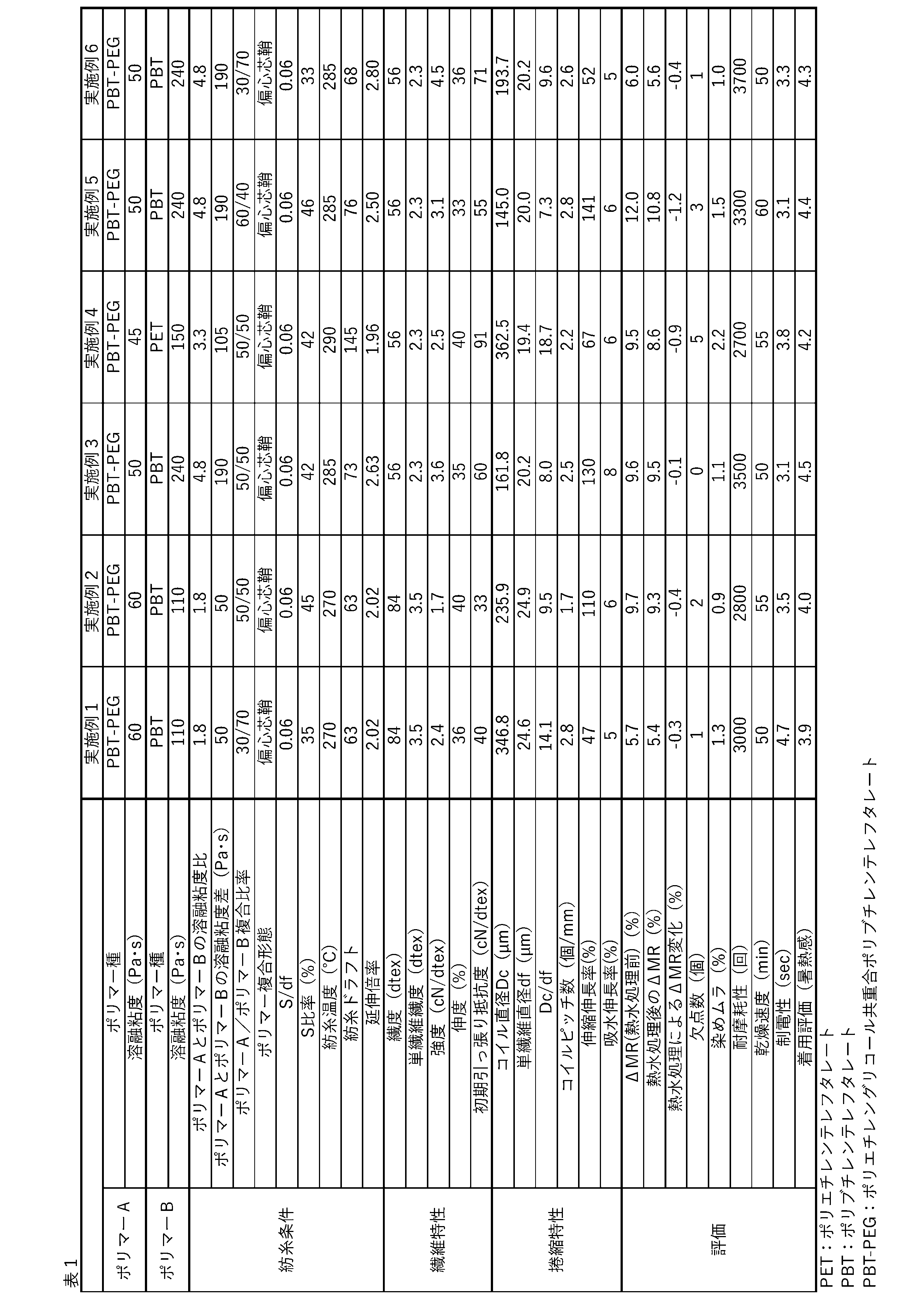
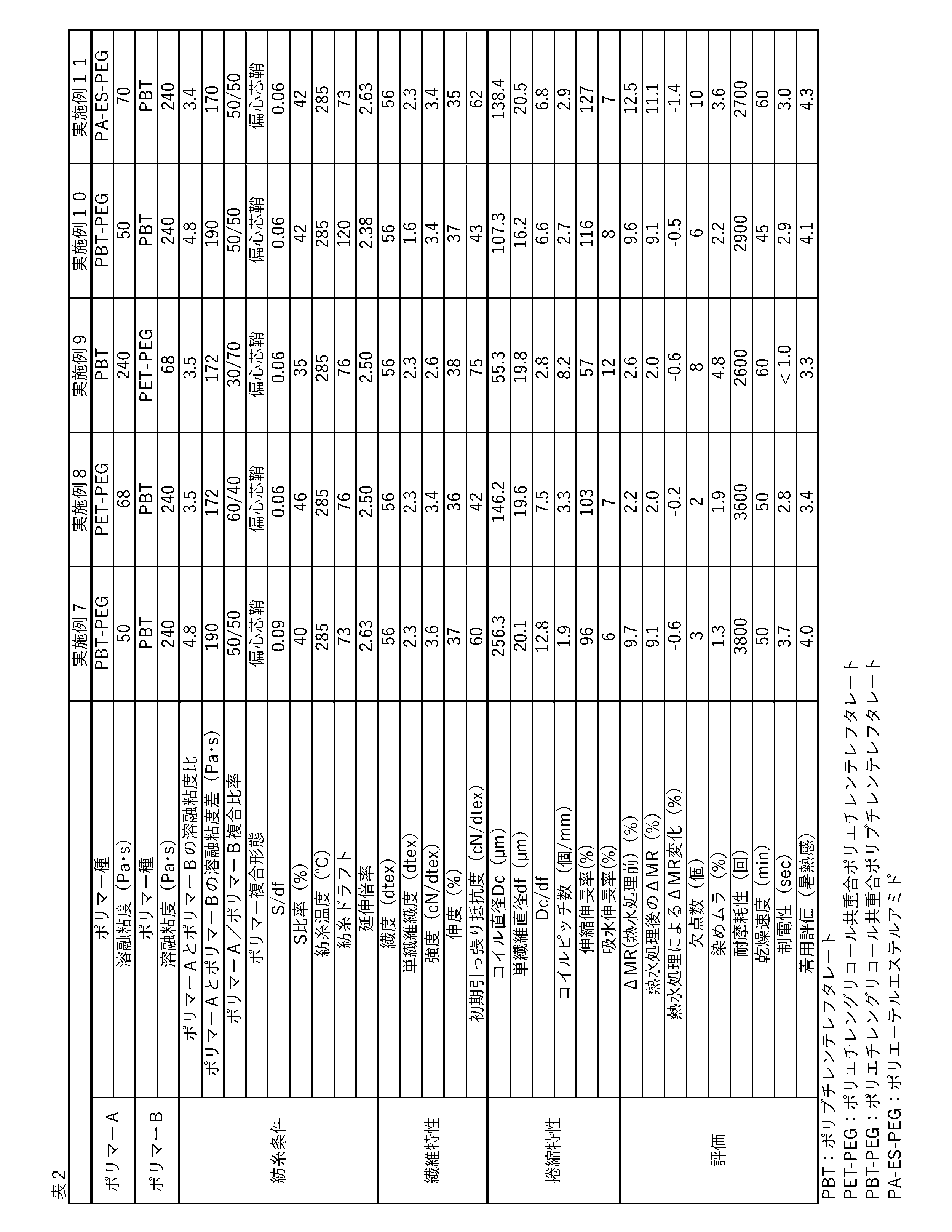
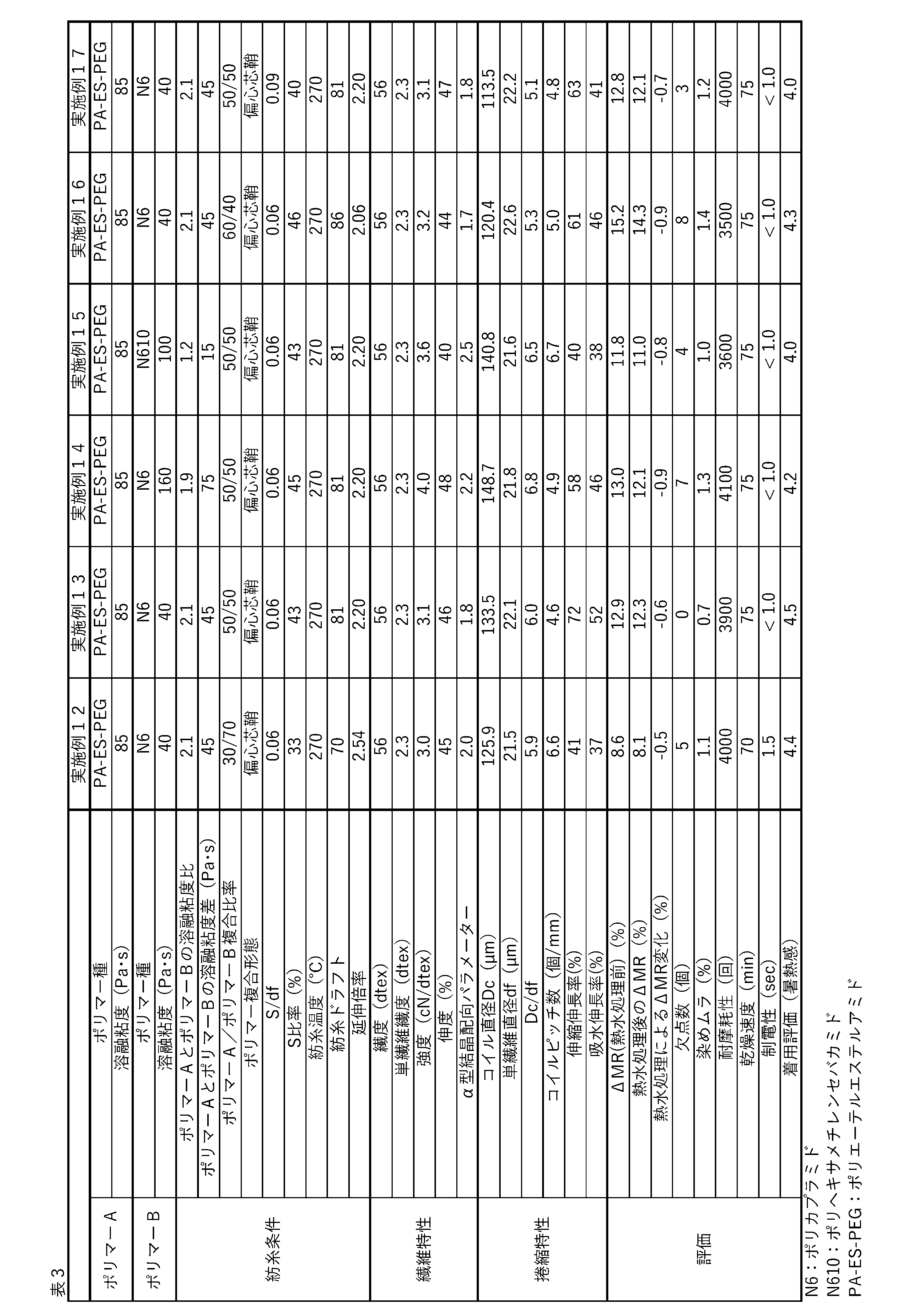
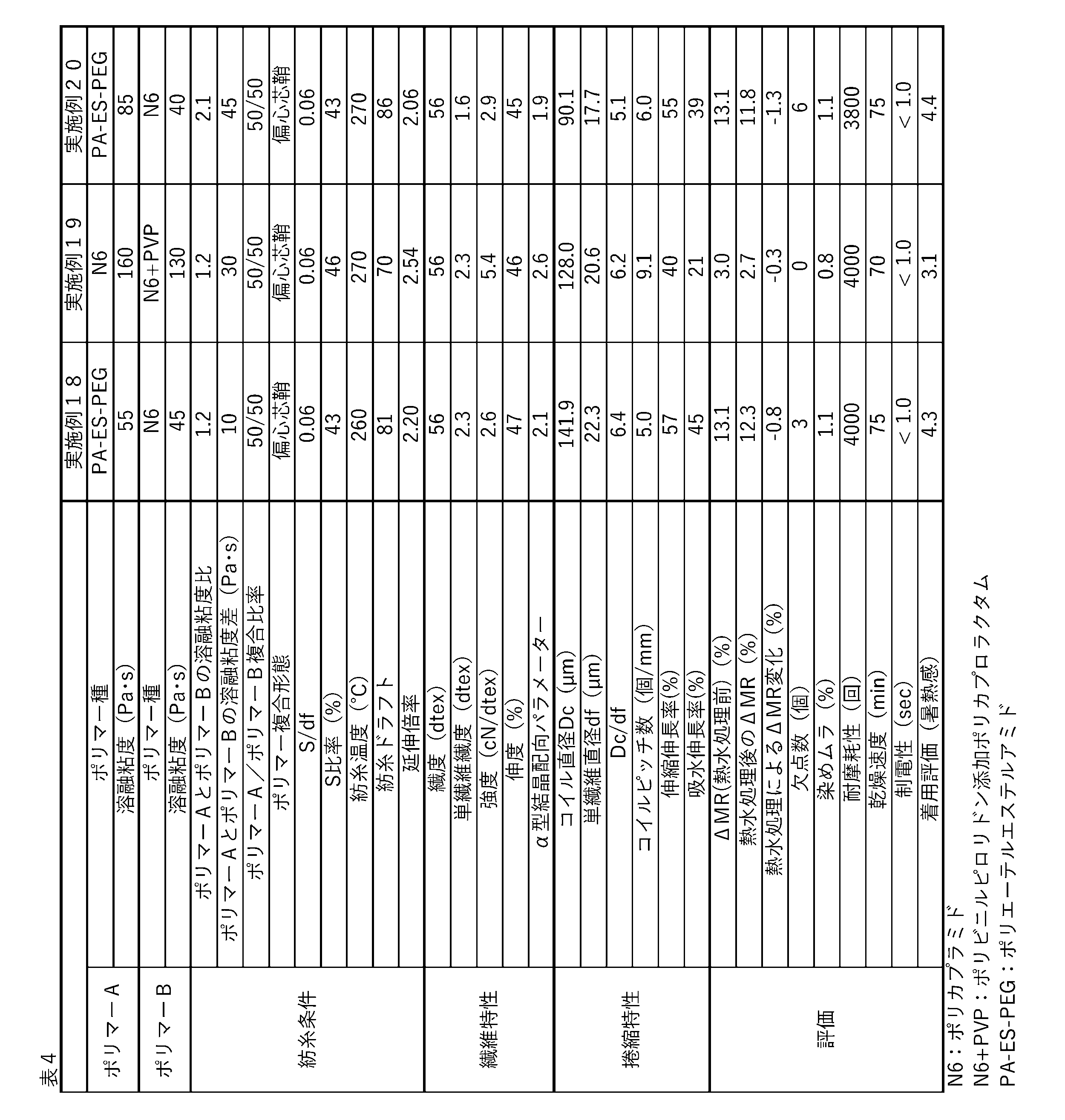
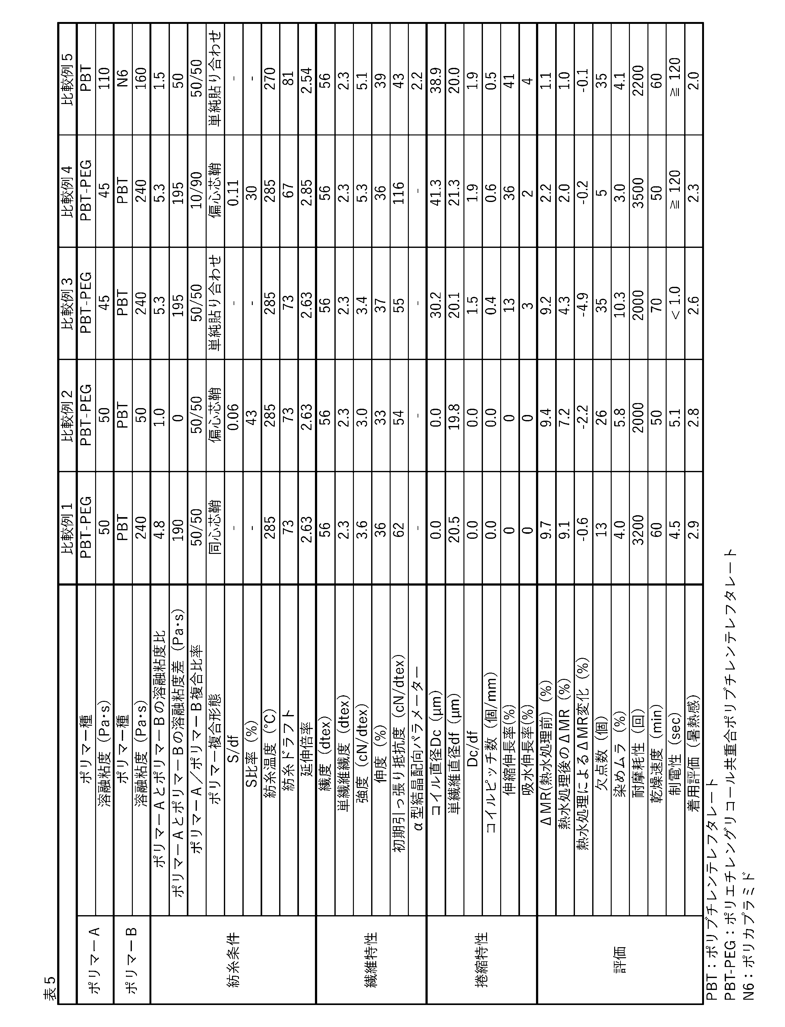
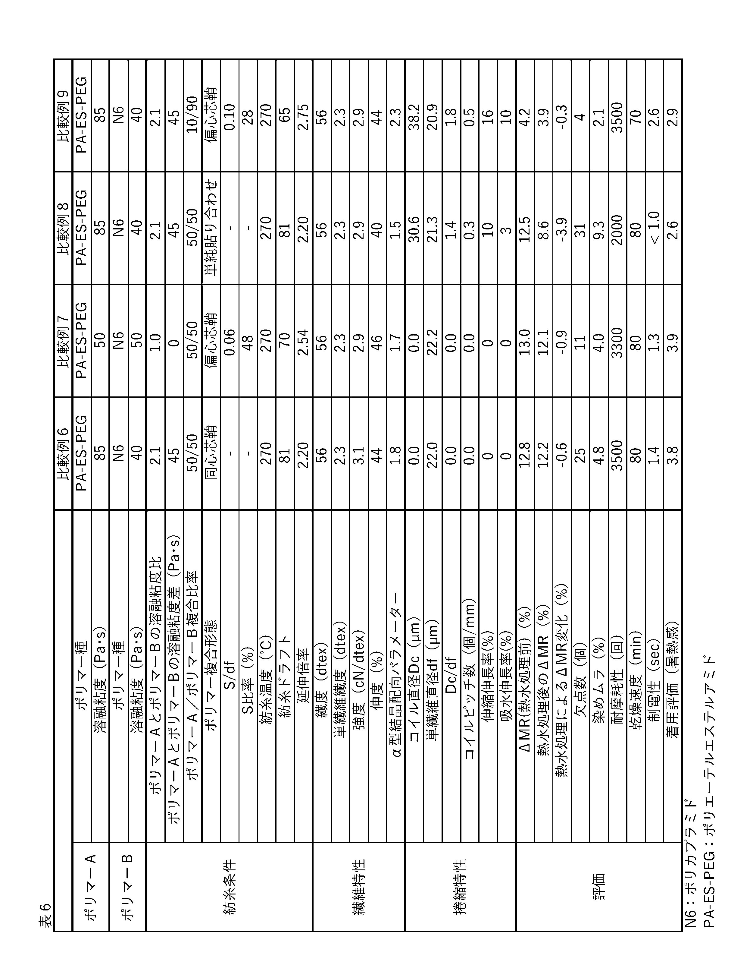


本出願は2022年2月14日出願の日本特許出願(特願2022-020215)に基づくものであり、その内容はここに参照として取り込まれる。
c 繊維横断面の中心
E ポリマーAとポリマーBの界面の任意の点
F ポリマーAとポリマーBの界面の接線に対する垂線と繊維表面の交点
M1、M2 捲縮繊維を構成する単繊維の捲縮形態における任意の隣り合う山の頂点
V 捲縮繊維を構成する単繊維の捲縮形態における谷の頂点
1 M1とM2を結んだ線と点Vの最短距離
2 コイル状の捲縮形態において任意の隣り合う山の頂点M1、M2間の距離
3 捲縮繊維を構成する単繊維の捲縮形態における繊維軸方向
4 ポリマーA
5 ポリマーB
6 ポリマーAとポリマーBの界面の接線
7 ポリマーAを覆っているポリマーBの最小となる厚み
8 単繊維直径
9 計量プレート
10 分配プレート
11 吐出プレート
Claims (4)
- ポリマーAおよびポリマーBの2種のポリマーからなる複合繊維であり、繊維軸方向にコイル状の捲縮形態を有し、コイル直径Dcと単繊維直径dfの比Dc/dfが2.0以上20.0以下、コイルピッチ数が1.0個/mm以上10.0個/mm以下であり、繊維横断面においてポリマーAがポリマーBで完全に覆われており、吸放湿パラメーターΔMRが2.0%以上である、捲縮繊維。
- 前記2種のポリマーのうち吸湿性の高いポリマーが、ポリマーAである、請求項1に記載の捲縮繊維。
- 前記2種のポリマーにおいて、前記2種のポリマーそれぞれの繰り返し単位を構成する主骨格中に同種の結合を有する、請求項1に記載の捲縮繊維。
- 請求項1~3のいずれか1項に記載の捲縮繊維を用いた繊維製品。
Priority Applications (2)
| Application Number | Priority Date | Filing Date | Title |
|---|---|---|---|
| CN202380020324.9A CN118647759A (zh) | 2022-02-14 | 2023-02-08 | 卷曲纤维 |
| JP2023510453A JPWO2023153459A1 (ja) | 2022-02-14 | 2023-02-08 |
Applications Claiming Priority (2)
| Application Number | Priority Date | Filing Date | Title |
|---|---|---|---|
| JP2022020215 | 2022-02-14 | ||
| JP2022-020215 | 2022-02-14 |
Publications (1)
| Publication Number | Publication Date |
|---|---|
| WO2023153459A1 true WO2023153459A1 (ja) | 2023-08-17 |
Family
ID=87564502
Family Applications (1)
| Application Number | Title | Priority Date | Filing Date |
|---|---|---|---|
| PCT/JP2023/004259 Ceased WO2023153459A1 (ja) | 2022-02-14 | 2023-02-08 | 捲縮繊維 |
Country Status (4)
| Country | Link |
|---|---|
| JP (1) | JPWO2023153459A1 (ja) |
| CN (1) | CN118647759A (ja) |
| TW (1) | TW202346670A (ja) |
| WO (1) | WO2023153459A1 (ja) |
Cited By (1)
| Publication number | Priority date | Publication date | Assignee | Title |
|---|---|---|---|---|
| JPWO2024157895A1 (ja) * | 2023-01-27 | 2024-08-02 |
Citations (6)
| Publication number | Priority date | Publication date | Assignee | Title |
|---|---|---|---|---|
| JP2000239918A (ja) * | 1999-02-22 | 2000-09-05 | Toray Ind Inc | 吸湿性に優れた扁平芯鞘複合繊維 |
| JP2003129352A (ja) * | 2001-10-26 | 2003-05-08 | Unitica Fibers Ltd | 伸縮性ポリアミド織物 |
| WO2009028564A1 (ja) * | 2007-08-31 | 2009-03-05 | Kuraray Kuraflex Co., Ltd. | 緩衝材用基材及びその用途 |
| JP2011162907A (ja) * | 2010-02-09 | 2011-08-25 | Toray Ind Inc | 捲縮糸および繊維構造体 |
| JP2019131941A (ja) * | 2018-01-31 | 2019-08-08 | 東レ株式会社 | 捲縮糸 |
| US20190360125A1 (en) * | 2018-05-22 | 2019-11-28 | Nano And Advanced Materials Institute Limited | Linear bi-component filament, fiber, or tape, and method of using thereof |
Family Cites Families (3)
| Publication number | Priority date | Publication date | Assignee | Title |
|---|---|---|---|---|
| JP2017214672A (ja) * | 2016-05-30 | 2017-12-07 | 東レ株式会社 | 吸湿性芯鞘複合糸が巻かれた繊維パッケージ |
| JP7505185B2 (ja) * | 2019-12-23 | 2024-06-25 | 東レ株式会社 | 紡績糸および繊維構造物 |
| JP7476619B2 (ja) * | 2020-03-31 | 2024-05-01 | 東レ株式会社 | ポリエステル複合繊維 |
-
2023
- 2023-02-08 JP JP2023510453A patent/JPWO2023153459A1/ja active Pending
- 2023-02-08 WO PCT/JP2023/004259 patent/WO2023153459A1/ja not_active Ceased
- 2023-02-08 CN CN202380020324.9A patent/CN118647759A/zh active Pending
- 2023-02-14 TW TW112105154A patent/TW202346670A/zh unknown
Patent Citations (6)
| Publication number | Priority date | Publication date | Assignee | Title |
|---|---|---|---|---|
| JP2000239918A (ja) * | 1999-02-22 | 2000-09-05 | Toray Ind Inc | 吸湿性に優れた扁平芯鞘複合繊維 |
| JP2003129352A (ja) * | 2001-10-26 | 2003-05-08 | Unitica Fibers Ltd | 伸縮性ポリアミド織物 |
| WO2009028564A1 (ja) * | 2007-08-31 | 2009-03-05 | Kuraray Kuraflex Co., Ltd. | 緩衝材用基材及びその用途 |
| JP2011162907A (ja) * | 2010-02-09 | 2011-08-25 | Toray Ind Inc | 捲縮糸および繊維構造体 |
| JP2019131941A (ja) * | 2018-01-31 | 2019-08-08 | 東レ株式会社 | 捲縮糸 |
| US20190360125A1 (en) * | 2018-05-22 | 2019-11-28 | Nano And Advanced Materials Institute Limited | Linear bi-component filament, fiber, or tape, and method of using thereof |
Cited By (3)
| Publication number | Priority date | Publication date | Assignee | Title |
|---|---|---|---|---|
| JPWO2024157895A1 (ja) * | 2023-01-27 | 2024-08-02 | ||
| WO2024157895A1 (ja) * | 2023-01-27 | 2024-08-02 | 東レ株式会社 | ポリアミド複合断面繊維、ポリアミドマルチフィラメント及びポリアミド複合断面仮撚加工糸 |
| JP7648000B2 (ja) | 2023-01-27 | 2025-03-18 | 東レ株式会社 | ポリアミド複合断面繊維、ポリアミドマルチフィラメント及びポリアミド複合断面仮撚加工糸 |
Also Published As
| Publication number | Publication date |
|---|---|
| TW202346670A (zh) | 2023-12-01 |
| CN118647759A (zh) | 2024-09-13 |
| JPWO2023153459A1 (ja) | 2023-08-17 |
Similar Documents
| Publication | Publication Date | Title |
|---|---|---|
| JP7135854B2 (ja) | 偏心芯鞘複合繊維および混繊糸 | |
| CN109415846B (zh) | 吸湿性优异的海岛型复合纤维、假捻丝和纤维结构体 | |
| JP7567986B2 (ja) | 複合口金及び複合繊維の製造方法 | |
| JP7135469B2 (ja) | 偏心芯鞘複合繊維を用いた織編物 | |
| JP3859672B2 (ja) | 複合繊維及びその製造方法 | |
| CN101010454A (zh) | 复合纤维 | |
| JP2025017421A (ja) | 複合仮撚加工糸 | |
| JP6090546B1 (ja) | 吸湿性芯鞘複合糸およびその製造方法 | |
| JP2017226941A (ja) | 織編物及びポリアミド芯鞘型混繊糸の元糸 | |
| CN118647759A (zh) | 卷曲纤维 | |
| JP7604891B2 (ja) | ポリアミド複合繊維および加工糸 | |
| JP7439960B2 (ja) | 複合繊維、マルチフィラメントおよび繊維製品 | |
| CN115803487A (zh) | 机织针织物及包含其的衣服 | |
| US20240360595A1 (en) | Composite fiber bundle and fiber product | |
| JP5357859B2 (ja) | 長短複合紡績糸 | |
| JP2008075224A (ja) | 嵩高性ポリエステル複合繊維糸 | |
| US20250188651A1 (en) | Composite false twisted yarn, woven fabric and clothing | |
| TW202223184A (zh) | 海島型複合纖維及含有海島型複合纖維之纖維製品 | |
| WO2023080184A1 (ja) | ポリエステル繊維および織物 | |
| HK40004617A (en) | Sea-islands type composite fiber having excellent moisture absorbability, textured yarn, and fiber structure | |
| JP2004323991A (ja) | 織物用複合繊維及びその製造法 | |
| HK40010518A (en) | Eccentric core-sheath composite fiber and combined filament yarn | |
| HK40010518B (en) | Eccentric core-sheath composite fiber and combined filament yarn | |
| JP2006083489A (ja) | 潜在捲縮性ポリエステル複合繊維糸条、織編物及びその製造方法 |
Legal Events
| Date | Code | Title | Description |
|---|---|---|---|
| WWE | Wipo information: entry into national phase |
Ref document number: 2023510453 Country of ref document: JP |
|
| 121 | Ep: the epo has been informed by wipo that ep was designated in this application |
Ref document number: 23752923 Country of ref document: EP Kind code of ref document: A1 |
|
| WWE | Wipo information: entry into national phase |
Ref document number: 202380020324.9 Country of ref document: CN |
|
| NENP | Non-entry into the national phase |
Ref country code: DE |
|
| 122 | Ep: pct application non-entry in european phase |
Ref document number: 23752923 Country of ref document: EP Kind code of ref document: A1 |