WO2023153329A1 - Dispositif d'entraînement pour véhicule - Google Patents
Dispositif d'entraînement pour véhicule Download PDFInfo
- Publication number
- WO2023153329A1 WO2023153329A1 PCT/JP2023/003570 JP2023003570W WO2023153329A1 WO 2023153329 A1 WO2023153329 A1 WO 2023153329A1 JP 2023003570 W JP2023003570 W JP 2023003570W WO 2023153329 A1 WO2023153329 A1 WO 2023153329A1
- Authority
- WO
- WIPO (PCT)
- Prior art keywords
- storage chamber
- oil
- opening
- case
- drain hole
- Prior art date
Links
Images


Classifications
-
- F—MECHANICAL ENGINEERING; LIGHTING; HEATING; WEAPONS; BLASTING
- F16—ENGINEERING ELEMENTS AND UNITS; GENERAL MEASURES FOR PRODUCING AND MAINTAINING EFFECTIVE FUNCTIONING OF MACHINES OR INSTALLATIONS; THERMAL INSULATION IN GENERAL
- F16H—GEARING
- F16H57/00—General details of gearing
- F16H57/04—Features relating to lubrication or cooling or heating
-
- H—ELECTRICITY
- H02—GENERATION; CONVERSION OR DISTRIBUTION OF ELECTRIC POWER
- H02K—DYNAMO-ELECTRIC MACHINES
- H02K7/00—Arrangements for handling mechanical energy structurally associated with dynamo-electric machines, e.g. structural association with mechanical driving motors or auxiliary dynamo-electric machines
- H02K7/10—Structural association with clutches, brakes, gears, pulleys or mechanical starters
- H02K7/116—Structural association with clutches, brakes, gears, pulleys or mechanical starters with gears
Definitions
- the present invention relates to a vehicular driving device that includes a case that accommodates a rotating electric machine that is a driving force source for wheels and a gear mechanism.
- Japanese Unexamined Patent Application Publication No. 2020-156296 discloses a vehicle drive system in which oil for lubricating (including cooling) a rotating electric machine (2) and gear mechanisms (4, 5) is accommodated inside a case (1) that accommodates them.
- Apparatus (1) is disclosed (in the background art, the numbers in parentheses are those of the referenced documents).
- the oil is stored in an oil sump (P) in the case (6), and part of the gears of the gear mechanism (4, 5) scrapes up the oil stored in the oil sump (P) and flows into the case (6).
- Oil is supplied to the bearings and the stator core (32) of the rotary electric machine (2) through a catch tank and an oil passage formed therein.
- the internal space of the case (6) is partitioned by a partition wall (61c) into a first accommodation chamber (81) that accommodates the rotating electric machine and a second accommodation chamber (82) that accommodates the gear mechanism.
- the partition wall (61c) is formed with an opening (68) that communicates with both storage chambers (81, 82). Oil can flow between the first storage chamber (81) and the second storage chamber (82) through this opening (68).
- the oil when oil can flow between two storage chambers, the oil may be biased in one of the storage chambers due to the inertia force associated with the tilt of the vehicle and the turning and acceleration of the vehicle. For example, if the oil is biased toward the first storage chamber (81) and the oil in the second storage chamber (82) decreases, the amount of oil scraped up by the gears will decrease, and the oil will flow through the catch tank and the oil passage. There is a risk that the supply will be inadequate. Further, in the case where the oil pump is housed in the first housing chamber (81), if the oil is biased toward the second housing chamber (82) and the oil in the first housing chamber (81) is reduced, Insufficient oil intake by the oil pump may occur. On the other hand, if the flow of oil between the two storage chambers is cut off and the oil is stored independently in each storage chamber, the drain holes for the respective storage chambers can be used when replacing the oil. is required, which may complicate the structure of the case.
- a vehicle drive device includes: a rotating electric machine that is a driving force source for wheels; an output member that is drivingly connected to the wheels; a gear mechanism that drives and connects the rotating electric machine and the output member;
- a vehicular drive device comprising a case that houses a rotating electric machine and the gear mechanism, wherein the case is partitioned by a partition wall portion of the case and includes a first housing chamber that houses the rotating electric machine and the gear.
- the gear mechanism supplies oil to a lubrication target location by raking up the oil inside the case, and the partition wall portion includes the first storage chamber and the second storage chamber.
- An opening communicating with the second storage chamber is formed, the opening allows the flow of oil from the first storage chamber to the second storage chamber, and allows oil to flow from the second storage chamber to the first storage chamber.
- a valve body is attached to regulate the flow of oil into the storage chamber.
- the partition wall portion that partitions the first storage chamber and the second storage chamber is formed with an opening that communicates the first storage chamber and the second storage chamber. is attached with a valve body so as to allow the flow of oil from the first storage chamber to the second storage chamber and to restrict the flow of oil from the second storage chamber to the first storage chamber. Therefore, even if the oil level is tilted due to the inclination of the vehicle or the inertial force due to turning or acceleration/deceleration, it is possible to limit the decrease in the oil level in the second storage chamber. That is, even if the oil surface is tilted, the gear mechanism accommodated in the second accommodation chamber scrapes up the oil inside the case, thereby supplying the oil to the lubrication target location.
- FIG. 10 is a diagram showing an example of the state of oil in the case when the vehicle drive device having the valve body in the opening is tilted;
- FIG. 10 is a diagram showing an example of the state of oil in the case when the vehicle drive device that does not have a valve body in the opening is tilted;
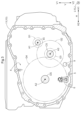
- Top view of the case body seen from the side of the first containment chamber Axial sectional view showing an example of a drain hole and a communication hole
- the vehicle drive device 100 includes a rotating electrical machine MG as a driving force source for wheels W, an output member OUT drivingly connected to the wheels W, and a rotating electrical machine MG. and an output member OUT, and a case 10 that accommodates the rotary electric machine MG and the gear mechanism TA.
- the case 10 includes at least a first storage chamber 1 and a second storage chamber 2 partitioned by a partition wall portion 4 of the case 10 .
- the rotating electric machine MG is accommodated in the first accommodation chamber 1 and the gear mechanism TA is accommodated in the second accommodation chamber 2 .
- the case 10 also includes a third storage chamber 3 that is partitioned from the first storage chamber 1 and the second storage chamber 2 by the peripheral wall portion 11a.
- the third accommodation chamber 3 accommodates an inverter INV that drives and controls the rotary electric machine MG.
- the rotating electric machine MG is arranged on the first axis A1, and the output member OUT is arranged on the second axis A2 parallel to the first axis A1.
- the gear mechanism TA is provided in a power transmission path between the rotating electrical machine MG and the output member OUT, and includes a plurality of gears G for drivingly connecting the rotating electrical machine MG and the output member OUT.
- the plurality of gears G also include a gear G that constitutes a counter gear mechanism CG, which will be described later.
- the counter gear mechanism CG is arranged on a third axis A3 which is parallel to the first axis A1 and the second axis A2.
- the gear mechanism TA also includes a differential gear mechanism DF that distributes the driving force transmitted from the rotary electric machine MG via the gears G to the pair of wheels W.
- the pair of output gears (side gears SG) of the differential gear mechanism DF correspond to the output member OUT.
- the wheel W and the output member OUT are connected via the output shaft DS.
- This output shaft DS can also be considered as an output member OUT.
- the pair of side gears SG of the differential gear mechanism DF correspond to the output member OUT and can also be considered to be included in the gear mechanism TA.
- driving connection refers to a state in which two rotating elements are connected so as to be able to transmit driving force, and the two rotating elements are connected so as to rotate integrally, or the two rotating elements It includes a state in which two rotating elements are connected so as to be able to transmit driving force via one or more transmission members.
- Such transmission members include various members that transmit rotation at the same speed or at different speeds, such as shafts, gear mechanisms, belts, and chains.
- the transmission member may include an engagement device for selectively transmitting rotation and driving force, such as a friction engagement device and a mesh type engagement device.
- an input gear G1 is connected to the rotor Rt of the rotary electric machine MG so as to rotate integrally with the rotor Rt.
- the input gear G1 is formed integrally with the input shaft IS on the outer peripheral side of the input shaft IS which is connected to the rotor shaft RS of the rotor Rt so as to rotate integrally with the rotor shaft RS.
- An input gear G1 is also included in the plurality of gears G that constitute the gear mechanism TA.
- the first axis A1, the second axis A2 and the third axis A3 are virtual axes different from each other, and are arranged parallel to each other as described above.
- the axial direction L is the direction parallel to the first axis A1. Since the first axis A1 and the second axis A2 are parallel to each other, the axial direction L is also parallel to the second axis A2. Further, since the third axis A3 is also parallel to the first axis A1 and the second axis A2, the axial direction L is also parallel to the third axis A3.
- first axial side L1 One side in the axial direction L (in this embodiment, the side on which the rotary electric machine MG is arranged with respect to the gear mechanism TA) is defined as the “first axial side L1”, and the opposite side is defined as the “second axial side L2”.
- the direction orthogonal to each of the first axis A1, second axis A2, and third axis A3 is defined as "radial direction R" with respect to each axis.
- the term “radial direction R” may simply be used.
- the direction along the vertical direction with the vehicle drive device 100 attached to the vehicle is defined as the "vertical direction V".
- the first vertical side V1, which is one side in the vertical direction V, is upward, and the second vertical side V2, which is the other side, is downward.
- the direction perpendicular to the axial direction L and the vertical direction V is referred to as the "width direction H".
- one side in the width direction H is called a width direction first side H1
- the other side is called a width direction second side H2.
- one direction of the radial direction R and the width direction H also coincide.
- terms relating to the direction, position, etc. of each member are concepts that include the state of having a difference due to an allowable manufacturing error.
- the direction of each member represents the direction when they are assembled in the vehicle drive system 100 .
- the width direction H corresponds to the longitudinal direction of the vehicle when the vehicle drive system 100 is attached to the vehicle.
- the case 10 includes a case main body 11 integrally formed to form the first storage chamber 1 , the second storage chamber 2 and the third storage chamber 3 .
- integrally molded refers to a unitary member formed of a common material, for example, as a single die casting.
- the case main body 11 may be composed of a plurality of members.
- the case 10 includes a first cover 10a that is joined to the case main body portion 11 from the first axial side L1, and a first cover 10a that is joined to the case main body portion 11 from the second axial side L2. It has a second cover 10b and a third cover 10c joined to the case main body 11 from the first vertical side V1.
- the third storage chamber 3 is positioned between the first storage chamber 1 and the second storage chamber 2 on the second side L2 in the axial direction from the first storage chamber 1 and on the first side V1 in the vertical direction from the second storage chamber 2. It is formed as a space partitioned against.
- the partition wall 4 partitions the first storage chamber 1 and the second storage chamber 2 in the axial direction L.
- the first storage chamber 1 is formed as a space surrounded by the case body 11 , the first cover 10 a and the partition wall 4 .
- the second storage chamber 2 is formed as a space surrounded by the case main body 11 , the second cover 10 b and the partition wall 4 .
- the third storage chamber 3 includes a peripheral wall portion 11a on the first vertical side V1 of the cylindrical case main body portion 11 relative to the second storage chamber 2, and a side wall erected on the first vertical side V1 from the peripheral wall portion 11a. It is formed as a space surrounded by the portion 11b and the third cover 10c.
- the rotating electrical machine MG is a rotating electrical machine (Motor/Generator) that operates with multi-phase alternating current (for example, 3-phase alternating current), and can function as both a motor and a generator.
- the rotary electric machine MG is powered by being supplied with power from a DC power supply (not shown), or supplies (regenerates) power generated by the inertial force of the vehicle to the DC power supply.
- the rotary electric machine MG has a stator St fixed to the case 10 and a rotor Rt rotatably supported inside the stator St in the radial direction R.
- the stator St includes a stator core and a stator coil Sc wound around the stator core, and the rotor Rt includes a rotor core and permanent magnets arranged in the rotor core.
- a rotor Rt of the rotary electric machine MG is connected to a rotor shaft RS, the rotor shaft RS is connected to an input shaft IS, and an input gear G1 is formed integrally with the input shaft IS on the outside in the radial direction R.
- the input gear G1 may be formed of a member separate from the input shaft IS and connected to the input shaft IS. That is, the rotor Rt is drivingly connected to the input gear G1 via the rotor shaft RS and the input shaft IS, and the input gear G1 rotates integrally with the rotor Rt. As will be described later, the input gear G1 is drivingly connected to the counter gear mechanism CG.
- the rotor shaft RS is rotatably supported with respect to the case 10 by a pair of first bearings B1, and the input shaft IS is rotatably supported with respect to the case 10 by a pair of second bearings B2.
- the pair of first bearings B1 are supported by the first cover 10a and the partition wall portion 4, respectively.
- the pair of second bearings B2 are respectively supported by the partition wall portion 4 and the second cover 10b.
- the counter gear mechanism CG is arranged on a third axis A3 parallel to the first axis A1 and the second axis A2, and drivingly connects the rotary electric machine MG and the differential gear mechanism DF via the input gear G1.
- the counter gear mechanism CG has two gears (first counter gear G2, second counter gear G3) connected by a shaft member (counter shaft CS). That is, the counter gear mechanism CG includes a first counter gear G2 arranged on the third shaft A3 and meshing with the input gear G1, and a differential gear mechanism DF which rotates integrally with the first counter gear G2. and a second counter gear G3 that meshes with the differential input gear G4.
- the counter shaft CS is rotatably supported with respect to the case 10 by a pair of third bearings B3.
- the third bearing B3 is supported by the partition wall portion 4 and the second cover 10b.
- the differential gear mechanism DF includes a differential case DC, a pair of pinion gears PG, and a pair of side gears SG.
- the pair of pinion gears PG and the pair of side gears SG are both bevel gears, and the differential gear mechanism DF of the present embodiment is a bevel gear type differential gear mechanism.
- the differential gear mechanism DF may also have a different configuration, for example a planetary gear differential gear mechanism.
- the differential case DC is a hollow member that houses a pair of pinion gears PG and a pair of side gears SG.
- the differential case DC is rotatably supported with respect to the case 10 by a pair of fourth bearings B4.
- the pair of fourth bearings B4 are respectively supported by the partition wall portion 4 and the second cover 10b.
- the differential case DC and the differential input gear G4 are connected so as to rotate integrally.
- the pair of pinion gears PG are arranged to face each other with a gap in the radial direction R with respect to the second axis A2.
- a pinion shaft PS is supported by the differential case DC so as to rotate integrally with the differential case DC, and a pair of pinion gears PG are attached to the pinion shaft PS.
- Each of the pair of pinion gears PG is rotatable (rotating) about the pinion shaft PS and rotatable (revolving) about the second axis A2.
- a pair of side gears SG are in mesh with the pair of pinion gears PG.
- the pair of side gears SG are arranged to face each other across the pinion shaft PS with a gap in the axial direction L so as to rotate about the second axis A2.
- Each side gear SG is drivingly connected to a pair of output shafts DS, respectively, and each output shaft DS is drivingly connected to a pair of wheels W, respectively.
- the first side gear S1 which is one of the pair of side gears SG, is connected to the connecting shaft JT
- the connecting shaft JT is connected to the first output shaft DS1, which is one of the pair of output shafts DS.
- a shaft DS1 is connected to one of a pair of wheels W.
- the connecting shaft JT is connected to rotate integrally with the first side gear S1 at one end side, extends in the axial direction L within the first housing chamber 1, and forms the first housing chamber 1 at the other end side.
- first output shaft DS1 is connected to the connecting shaft JT so as to rotate integrally, and the other end is supported by a member (not shown) inside the vehicle.
- a first seal member B6 supported by the first cover 10a is provided on the other end side of the first output shaft DS1.
- a second side gear S2, which is the other of the pair of side gears SG, is connected to a second output shaft DS2, which is the other of the pair of output shafts DS, and the second output shaft DS2 is connected to the other of the pair of wheels W.
- One end of the second output shaft DS2 is connected to rotate integrally with the second side gear S2, and the other end is supported by a member (not shown) inside the vehicle.
- a second seal member B7 supported by a second cover 10b forming the second housing chamber 2 is provided on the other end side of the second output shaft DS2.
- the differential gear mechanism DF outputs torque transmitted from the rotor Rt via the input gear G1, the counter gear mechanism CG (first counter gear G2, second counter gear G3), and the differential input gear G4.
- the driving force is distributed to a pair of side gears SG as members OUT and transmitted to a pair of wheels W.
- the vehicle drive device 100 can transmit the torque of the rotary electric machine MG to the wheels W to drive the vehicle.
- the connecting shaft JT can also be considered as the output member OUT.
- the rotary electric machine MG and the gear mechanism TA that constitute the vehicle drive device 100 are lubricated with oil (including cooling).
- oil including cooling
- the bearings (B1 to B5), the seal members (B6, B7), the stator coil Sc of the rotary electric machine MG, and the like are lubricated and cooled by oil.
- the lubricating oil is a mechanical type (not shown) that is driven by one or more of the driving force sources of the wheels W (including the above-described rotating electrical machine MG and an internal combustion engine if a separate internal combustion engine is provided).
- the vehicle drive system 100 is formed with oil passages to lubrication target locations, and oil is supplied from these oil pumps.
- the oil passages from the oil pump are formed for all lubrication target locations, the oil passages may become complicated and the vehicle drive device 100 may become large. Further, when the number of oil passages increases, it may be necessary to increase the discharge capacity of the oil pump.
- oil is supplied from the oil pump to a portion of the vehicle drive device 100 (for example, the stator coil Sc of the rotary electric machine MG in this embodiment) to be lubricated. is supplied, and lubrication of other lubrication target locations (eg, gear G and bearings (B1 to B5) in this embodiment) is often performed using the oil after lubricating the lubrication target location.
- the oil used for lubrication drops due to gravity and is stored in the case 10 (an oil reservoir located at the bottom of the case 10).
- the first counter gear G2 and the differential input gear G4 are used as rotating members for raking up the oil from the oil pool on the bottom of the case 10 .
- the differential input gear G4 whose tooth surface is positioned closest to the second side V2 in the vertical direction mainly functions as the gear G for scraping.
- the gear mechanism TA rakes up the oil inside the case 10 to supply the oil to the lubrication target location.
- the parts to be lubricated by raking of the gear mechanism TA (here, mainly the differential input gear G4) are the gears G and bearings (B1 to B5) constituting the gear mechanism TA.
- lubrication target locations exist in both the first storage chamber 1 and the second storage chamber 2 . Therefore, the lubricated oil drops in the first storage chamber 1 and the second storage chamber 2 and accumulates at the bottom of each.
- the raking gear G is arranged in the second storage chamber 2 as described above.
- an oil pump may be arranged in the first housing chamber 1 . Therefore, it is preferable that both storage chambers are appropriately filled with oil.
- the partition wall portion 4 that partitions the first storage chamber 1 and the second storage chamber 2 so that the oil can flow between the first storage chamber 1 and the second storage chamber 2 has a As shown in 3 and the like, an opening 5 that communicates the first storage chamber 1 and the second storage chamber 2 is formed. As shown in FIGS. 3 to 8, the opening 5 allows oil to flow from the first storage chamber 1 to the second storage chamber 2, and allows oil to flow from the second storage chamber 2 to the first storage chamber 1.
- a valve body 6 is attached so as to regulate the flow of oil to.
- the valve body 6 includes a plate 61, a fixed portion 62, a hinge portion 63, and a conical portion 64. are connected to each other so as to be able to swing relative to each other.
- the fixed portion 62 is fixed to the partition wall portion 4 by a fastening member 69 from the second storage chamber 2 side. Therefore, the valve body 6 is arranged such that the plate 61 swings while the fixing portion 62 and the hinge portion 63 are fixed to the surface (mounting surface 42) of the partition wall portion 4 on the side of the second housing chamber 2. It is attached to the partition wall portion 4 .
- the plate 61 has an area larger than that of the opening 5, and a conical portion 64 is formed in the central portion of the plate 61. As shown in FIG.
- the conical portion 64 is formed to protrude toward the first housing chamber 1 side (protrudes to the portion of the plate 61 surrounding the central portion) with the valve body 6 attached to the partition wall portion 4 .
- the valve body 6 is in a posture (first It is configured to take the posture P1).
- first posture P1 As shown in FIG. 5, the valve body 6 is in the first posture P1, as shown in FIG. It can be freely circulated to and from the second storage chamber 2 . In other words, bidirectional oil flow is allowed between the first storage chamber 1 and the second storage chamber 2 .
- the opening portion 5 is closed by the valve body 6 (the plate 61 and the conical portion 64), as indicated by the broken line in FIG. be
- the fluid pressure presses the plate 61 in the direction of the partition wall portion 4, so that the flow from the second storage chamber 2 to the first storage chamber 2 is prevented.
- Oil flow to chamber 1 is blocked by valve body 6 .
- the plate 61 is pushed away from the partition wall 4 by the fluid pressure.
- the opening 5 is opened when the force pressing against 4 is exceeded. Therefore, the oil flows from the first storage chamber 1 to the second storage chamber 2 without being blocked by the valve body 6 .
- the angle (opening angle ⁇ ) between the first attitude P1 and the second attitude P2 is about 5 to 10 degrees.
- the locations to be lubricated in the vehicle drive device 100 are present in both the first accommodation chamber 1 and the second accommodation chamber 2 .
- the differential input gear G4 by raking up oil from the oil pool at the bottom of the case 10, especially from the oil pool at the bottom of the second storage chamber 2, by the differential input gear G4, the input gear G1, first counter gear G2, second counter gear G3, first bearing B1, second bearing B2, third bearing B3, fourth bearing B4, fifth bearing B5, first sealing member B6, second sealing member B7 etc. can be lubricated.
- the stator coil Sc of the rotary electric machine MG can be cooled via a catch tank and an oil passage (not shown).
- oil that lubricates the first bearing B1 and oil that cools the stator coil Sc drops into the first storage chamber 1 and is stored in an oil reservoir at the bottom of the first storage chamber 1 .
- the oil stored in the first storage chamber 1 flows into the oil reservoir of the second storage chamber 2 through the opening 5 of the partition wall 4 .
- the oil when the oil can flow between the two storage chambers in this way, the oil may be biased in one of the storage chambers due to the inertia force associated with the inclination of the vehicle, turning, acceleration, etc. of the vehicle.
- the oil when the oil is concentrated on the side of the first storage chamber 1 and the oil in the second storage chamber 2 decreases, the amount of oil raked up by the gear G decreases, and the oil flows through the catch tank and the oil passage. In some cases, the oil supply to the lubrication target location becomes insufficient.
- both the differential input gear G4 and the first counter gear G2 are positioned above the level of the accumulated oil LQ, and are in a state in which they cannot rake up the oil.
- the opening 5 is provided with the valve body 6 as described above. As shown in FIG. 6 , the opening 5 is closed by the valve body 6 when the vehicle drive device 100 is tilted toward the first side L1 in the axial direction. As a result, the flow of oil from the second storage chamber 2 to the first storage chamber 1 is blocked, the amount of oil flowing out to the first storage chamber 1 is suppressed, and the oil sufficient to be scraped up by the gear G is not supplied to the first storage chamber 1. 2 Stay in Containment Chamber 2. In the example shown in FIG. 6 , part of the tooth surface of the differential input gear G4 and all of the tooth surface of the first counter gear G2 are immersed in the oil LQ accumulated in the second housing chamber 2 . Therefore, in the example shown in FIG. 6, the differential input gear G4 and the first counter gear G2 can rake up the oil.
- the opening 5 formed in the partition wall 4 that partitions the first storage chamber 1 and the second storage chamber 2 allows oil to flow from the first storage chamber 1 to the second storage chamber 2.
- the valve body 6 is attached so as to restrict the flow of oil from the second storage chamber 2 to the first storage chamber 1, the oil level is lowered by inertial force due to inclination of the vehicle and turning or acceleration/deceleration. Even if it is tilted, it is possible to limit the lowering of the oil level in the second housing chamber 2 . Further, by restricting the lowering of the oil level in the second housing chamber 2, the gear G can rake up the oil to appropriately supply the lubrication target location.
- the rotating electrical machine MG is accommodated in the first accommodation chamber 1, and the gear mechanism TA is accommodated in the second accommodation chamber 2.
- the oil level in the second storage chamber 2 is suppressed.
- lubricating (cooling) oil is supplied to each part of the vehicle drive device 100 by raking up the gear G included in the gear mechanism TA housed in the second housing chamber 2, the oil surface of the gear is G, it is possible to prevent the gear G from impeding the raking up of the oil. That is, when the configuration of the present embodiment is applied to a configuration in which the gear mechanism TA is accommodated in the second accommodation chamber 2, the gear G can rake up the oil to properly lubricate each part.
- the vehicle drive device 100 includes an oil pump (electric oil pump) (not shown) that supplies oil to the rotary electric machine MG, and a strainer (not shown) that removes impurities from the oil sucked by the oil pump.
- the strainer is housed in the second housing chamber 2 .
- An oil pump is also housed in the second housing chamber 2 .
- the partition wall portion 4 is formed with a strainer arrangement hole 9 in which a strainer for removing impurities from the oil sucked by the oil pump is arranged.
- a valve body may be arranged in this strainer arrangement hole 9 as well.
- the oil stored inside the case 10 deteriorates due to contamination with dust caused by bearing friction and the like, and changes in composition (for example, oxidation) due to contact with high-temperature members such as the stator coil Sc. Since degraded oil deteriorates the lubricating performance and cooling performance, the oil in the case 10 is periodically replaced.
- the drain hole communicating with the first storage chamber 1 and the second If a drain hole communicating with the housing chamber 2 is provided, the structure of the case 10 becomes complicated, and the cost may increase. Also, when replacing the oil, it is necessary to remove the oil from two locations, which may increase the number of man-hours and raise the maintenance cost.
- the structure of the case 10 can be simplified and the number of parts can be reduced as compared with the case where drain holes are provided in each of the first storage chamber 1 and the second storage chamber 2 .
- the drain hole 7 is blocked by a drain plug 79, the oil in both the first storage chamber 1 and the second storage chamber 2 can be drained simply by pulling out this one drain plug 79, so the oil can be drained. It is possible to improve the efficiency of the work for
- the communication hole 8 is formed inside the bottom wall portion 21 .
- the communication hole 8 is formed in the first opening 81 that opens to the side surface of the drain hole 7 and the opposing surface of the bottom wall portion 21 facing the second storage chamber 2 (second storage chamber facing surface 22). and a second opening 82 that opens.
- the communication hole 8 is formed so as to communicate between the first opening 81 and the second opening 82 . That is, when the vehicle drive system 100 is mounted on the vehicle, the drain hole 7 and the communication hole 8 can be provided at a low position in the case 10 , so that the oil in the case 10 can be properly drained through the drain hole 7 . can be discharged.
- the position of the lower end of the first opening 81 (communication portion lower end position Z2) is the opening of the drain hole 7 on the side of the first containing chamber 1 (drain opening 71). ) (drain opening position Z1) (vertically second side V2).
- the oil in the second housing chamber 2 can be discharged until the lower position (the lower end position Z2 of the communicating portion) of the communicating hole 8 reaches the oil level.
- the opening 5 formed in the partition wall 4 is located at a position lower than the drain opening 71 that is the opening of the drain hole 7 on the side of the first storage chamber 1 , the oil is discharged through the opening 5 . flows into the second storage chamber 2 . Oil can be discharged from the second storage chamber 2 through the communication hole 8 and the drain hole 7 .
- the drain opening 71 is preferably arranged at the lowest position in the first storage chamber 1, but even if such an arrangement is difficult, the oil in the first storage chamber 1 can be properly drained. can.
- the drain hole 7 is blocked with the drain plug 79 fixed to the drain hole 7 as shown by the dashed line in FIG. Not only is the communication blocked, but the communication between the second storage chamber 2 and the drain hole 7 via the communication hole 8 is also blocked. That is, when the drain plug 79 is fixed to the drain hole 7, communication between the first storage chamber 1 and the second storage chamber 2 through the communication hole 8 is blocked. Therefore, with the drain plug 79 fixed to the drain hole 7, it is possible to restrict the flow of oil between the first storage chamber 1 and the second storage chamber 2 via the communication hole 8. .
- the vehicle drive device 100 having a three-axis structure in which the three axes of the first axis A1, the second axis A2, and the third axis A3 are arranged in parallel has been described as an example.
- the device 100 may have, for example, a two-axis configuration in which two axes, a first axis A1 and a second axis A2, are arranged in parallel.
- the vehicle drive device 100 has a configuration in which one or more axes different from the first axis A1, the second axis A2, and the third axis A3 are further arranged in parallel, and four or more axes are arranged in parallel. good too.
- the vehicle drive device 100 may have a uniaxial configuration in which the rotary electric machine MG, the gear G, and the differential gear mechanism DF are arranged on the same shaft.
- the vehicle drive system 100 including the rotary electric machine MG as the drive force source for the wheels W was exemplified.
- a hybrid drive device including both the engine and the rotary electric machine MG for example, various types of hybrid drive devices such as a so-called 1-motor parallel system and a 2-motor split system) may be used.
- the first housing chamber 1 houses the rotary electric machine MG
- the second housing chamber 2 houses the gear mechanism TA.
- the gear mechanism TA may be accommodated in the first accommodation chamber 1 and the rotary electric machine MG may be accommodated in the second accommodation chamber 2 .
- an oil pump may be accommodated in the second accommodation chamber 2 together with the rotary electric machine MG, and a valve body 6 may be provided to block the opening 5 so that the oil pump can sufficiently suck in oil.
- the bottom wall portion 21 of the first storage chamber 1 is provided with the second storage chamber facing surface 22 , and the second opening 82 of the communication hole 8 opens to the second storage chamber facing surface 22 .
- the partition wall portion 4 is continuous with the bottom wall portion 21, and the second opening portion 82 is provided on the surface (mounting surface 42) of the second storage chamber 2 in the partition wall portion 4, and the partition wall portion 4 and the bottom A communication hole 8 may be formed inside the wall portion 21 .
- the position of the lower end of the first opening 81 corresponds to the position of the opening (drain opening 71) of the drain hole 7 on the side of the first storage chamber 1 (drain opening position).
- Z1) is exemplified below (vertically second side V2) (see FIG. 9). This is because the position of the bottom of the second storage chamber 2 in the vertical direction V (lowermost position Z3 of the second storage portion) is the position of the bottom of the first storage chamber 1 in the vertical direction V (the drain opening position in the example of FIG. 9). It is particularly useful when it is lower (in the case of the vertical second side V2) than (approximately equal to Z1).
- the configuration is not limited to such a configuration.
- the position of the bottom of the second storage chamber 2 in the vertical direction V is the position of the bottom of the first storage chamber 1 in the vertical direction V.
- drain opening position Z1 in the case of the vertical direction first side V1
- the position of the lower end of the first opening 81 (communication portion lower end position Z2) side opening (drain opening 71) position
- drain opening position Z1 (vertical direction first side V1).
- the drain hole 7 is formed in the bottom wall portion 21 of the first storage chamber 1 to communicate the first storage chamber 1 with the outside of the case 10.
- the form provided with the communication hole 8 which connects the 2nd storage chamber 2 and the drain hole 7 was illustrated.
- a drain hole (not shown) may be formed in the bottom wall portion (no reference numeral) of the second storage chamber 2 to communicate between the first storage chamber 1 and the outside of the case 10. .
- a drain plug is also inserted into this drain hole and fixed detachably.
- this drain hole is formed in the bottom wall portion of the second storage chamber 2 , it communicates the first storage chamber 1 with the outside of the case 10 and communicates the second storage chamber 2 with the outside of the case 10 . It will be. That is, the bottom wall portion of the second storage chamber 2 is formed with a drain hole that communicates the first storage chamber 1 with the outside of the case 10 and communicates the second storage chamber 2 with the outside of the case 10 . there is Therefore, when the vehicle drive system 100 is mounted on the vehicle, the oil in the case 10 is drained from the first storage chamber 1 and the second storage chamber 2 through the drain hole formed at a low position in the case 10. can be discharged properly.
- the opening 5 formed between the first storage chamber 1 and the second storage chamber is provided with the valve body 6 so that the second storage chamber 2 can be opened from the first storage chamber 2 by providing the valve body 6 .
- the flow of oil to chamber 1 is regulated.
- the drain hole formed in the bottom wall portion of the second storage chamber 2 also serves as a drain hole that communicates the first storage chamber 1 with the outside of the case 10 . Therefore, when the vehicle drive system 100 is mounted on the vehicle, the oil in the case 10 is drained from the first storage chamber 1 and the second storage chamber 2 through the drain hole formed at a low position in the case 10. can be discharged properly.
- a vehicle drive system includes a rotating electric machine (MG) as a driving force source for a wheel (W), an output member (OUT) drivingly connected to the wheel (W), and the rotating A vehicle comprising: a gear mechanism (TA) drivingly connecting an electric machine (MG) and an output member (OUT); and a case (10) housing the rotating electric machine (MG) and the gear mechanism (TA).
- MG rotating electric machine
- OUT output member
- TA gear mechanism
- the case (10) is partitioned by a partition wall (4) of the case (10), and includes a first accommodation chamber (1) that accommodates the rotating electric machine (MG) and the a second housing chamber (2) housing a gear mechanism (TA), the gear mechanism (TA) raking up the oil inside the case (10) to supply oil to a lubrication target location;
- the partition wall (4) is formed with an opening (5) that communicates between the first storage chamber (1) and the second storage chamber (2). Permitting the flow of oil from the first storage chamber (1) to the second storage chamber (2) and restricting the flow of oil from the second storage chamber (2) to the first storage chamber (1)
- the valve body (6) is attached as follows.
- the partition wall portion that partitions the first storage chamber and the second storage chamber is formed with an opening that communicates the first storage chamber and the second storage chamber. is attached with a valve body so as to allow the flow of oil from the first storage chamber to the second storage chamber and to restrict the flow of oil from the second storage chamber to the first storage chamber. Therefore, even if the oil level is tilted due to the inclination of the vehicle or the inertial force due to turning or acceleration/deceleration, it is possible to limit the decrease in the oil level in the second storage chamber. That is, even if the oil surface is tilted, the gear mechanism accommodated in the second accommodation chamber scrapes up the oil inside the case, thereby supplying the oil to the lubrication target location.
- the vehicle drive system (100) includes an oil pump that supplies oil to the rotating electrical machine (MG), and a strainer that removes impurities from the oil that is sucked by the oil pump. It is suitable if it is accommodated in the accommodation chamber (2).
- the oil supplied to the rotating electric machine (MG) is supplied to the rotating electric machine (MG) through the strainer provided in the second storage chamber (2) in which the oil level is restricted from lowering. It can be sucked by an oil pump.
- the vehicle drive device (100) includes a drain hole provided in the bottom wall portion (21) of the first accommodation chamber (1) for communicating the first accommodation chamber (1) with the outside of the case (10). (7) is formed, and a drain plug (79) is inserted into and detachably fixed to the drain hole (7) to communicate the second storage chamber (2) and the drain hole (7). It is preferable to have a communication hole (8).
- each of the first storage chamber (1) and the second storage chamber (2) has an oil drain hole (drain hole (7) of the first storage chamber (1) and a second storage chamber separate from it).
- the structure of the case (10) can be simplified and the number of parts can be reduced.
- the drain hole (7) is blocked by a drain plug (79), but by removing this one drain plug (79), both the first storage chamber (1) and the second storage chamber (2) can be drained. Since the oil can be discharged, the efficiency of the work for discharging the oil can also be improved.
- the bottom wall portion (21) has a second storage chamber facing surface (22) facing the second storage chamber (2), and the bottom wall portion (21)
- the communication hole (8) is formed in the interior of the, and the communication hole (8) is connected to the first opening (81) opening on the side surface of the drain hole (7) and the second storage chamber facing surface (22) It is preferable that a second opening (82) that opens to the .
- the drain hole (7) and the communication hole (8) can be provided at a low position in the case (10).
- the oil in the case (10) can be properly discharged through (7).
- the lower end (Z2) of the first opening (81) is located further than the opening (71) of the drain hole (7) on the side of the first storage chamber (1). It is preferably arranged on the lower side (V2).
- the oil in the first storage chamber (1) is properly discharged through the drain hole (7), and the oil in the second storage chamber (2) is discharged through the opening (5). Even if the flow of oil to the 1 storage chamber (1) is restricted by the valve body (6), the communication hole (8) and the drain hole (7) connected to the side surface (78) of the drain hole (7) ) to be properly discharged.
- the vehicle drive system (100) is configured such that the drain plug (79) is fixed to the drain hole (7), and the second storage chamber (2) and the drain plug (2) are connected through the communication hole (8).
- the communication with the drain hole (7) is blocked.
- the drain plug (79) when the drain plug (79) is fixed to the drain hole (7), the drain hole (7) is blocked and the first storage chamber (1) is separated from the outside of the case (10). Not only is the communication blocked, but the communication between the second storage chamber (2) and the drain hole (7) via the communication hole (8) is also blocked. That is, when the drain plug (79) is fixed to the drain hole (7), communication between the first storage chamber (1) and the second storage chamber (2) through the communication hole (8) is also blocked. Therefore, when the drain plug (79) is fixed to the drain hole (7), instead of discharging the oil from the case (10), the first storage chamber (1) and the first storage chamber (1) are connected via the communication hole (8). It is possible to limit the flow of oil to and from the 2 storage chamber (2).
- a drain hole is formed in the bottom wall portion of the second accommodation chamber (2) to communicate the first accommodation chamber (1) with the outside of the case (10). It is preferable to have
- this drain hole is formed in the bottom wall of the second storage chamber (2), it communicates the first storage chamber (1) with the outside of the case (10), and also connects the second storage chamber (2) with the outside. It communicates with the outside of the case (10). Therefore, when the vehicle drive device (100) is mounted on the vehicle, the drain hole formed at a low position in the case (10) allows the first storage chamber (1) and the second storage chamber (2) to flow through the drain hole. ) can appropriately discharge the oil in the case (10).
Landscapes
- Engineering & Computer Science (AREA)
- General Engineering & Computer Science (AREA)
- Mechanical Engineering (AREA)
- Power Engineering (AREA)
- General Details Of Gearings (AREA)
Abstract
Selon l'invention, une machine électrique tournante et un mécanisme d'engrenage sont reçus dans un boîtier qui comprend une première chambre de réception (1) et une seconde chambre de réception (2) qui sont séparées par une partie paroi de séparation (4). Le mécanisme d'engrenage fournit une huile à une partie cible de lubrification en raclant l'huile dans le boîtier. Une ouverture (5) par le biais de laquelle la première chambre de réception (1) et la seconde chambre de réception (2) sont en communication l'une avec l'autre est formée dans la partie paroi de séparation (4). Un élément de soupape (6) est fixé au niveau de l'ouverture (5) de façon à permettre l'écoulement de l'huile de la première chambre de réception (1) vers la seconde chambre de réception (2) et à limiter l'écoulement de l'huile de la seconde chambre de réception (2) vers la première chambre de réception (1).
Applications Claiming Priority (2)
| Application Number | Priority Date | Filing Date | Title |
|---|---|---|---|
| JP2022-019677 | 2022-02-10 | ||
| JP2022019677 | 2022-02-10 |
Publications (1)
| Publication Number | Publication Date |
|---|---|
| WO2023153329A1 true WO2023153329A1 (fr) | 2023-08-17 |
Family
ID=87564364
Family Applications (1)
| Application Number | Title | Priority Date | Filing Date |
|---|---|---|---|
| PCT/JP2023/003570 WO2023153329A1 (fr) | 2022-02-10 | 2023-02-03 | Dispositif d'entraînement pour véhicule |
Country Status (1)
| Country | Link |
|---|---|
| WO (1) | WO2023153329A1 (fr) |
Citations (5)
| Publication number | Priority date | Publication date | Assignee | Title |
|---|---|---|---|---|
| JPS549731Y2 (fr) * | 1974-10-02 | 1979-05-08 | ||
| JPS5524508U (fr) * | 1978-08-02 | 1980-02-16 | ||
| JPS62163658U (fr) * | 1986-04-07 | 1987-10-17 | ||
| JP2003169448A (ja) * | 2001-12-03 | 2003-06-13 | Nissan Motor Co Ltd | ハイブリッド車両の駆動装置 |
| JP2008089016A (ja) * | 2006-09-29 | 2008-04-17 | Toyota Motor Corp | 動力伝達装置および車両 |
-
2023
- 2023-02-03 WO PCT/JP2023/003570 patent/WO2023153329A1/fr unknown
Patent Citations (5)
| Publication number | Priority date | Publication date | Assignee | Title |
|---|---|---|---|---|
| JPS549731Y2 (fr) * | 1974-10-02 | 1979-05-08 | ||
| JPS5524508U (fr) * | 1978-08-02 | 1980-02-16 | ||
| JPS62163658U (fr) * | 1986-04-07 | 1987-10-17 | ||
| JP2003169448A (ja) * | 2001-12-03 | 2003-06-13 | Nissan Motor Co Ltd | ハイブリッド車両の駆動装置 |
| JP2008089016A (ja) * | 2006-09-29 | 2008-04-17 | Toyota Motor Corp | 動力伝達装置および車両 |
Similar Documents
| Publication | Publication Date | Title |
|---|---|---|
| CN109790914B (zh) | 车辆用驱动装置 | |
| JP6664302B2 (ja) | 車両用駆動装置 | |
| JP3705193B2 (ja) | ハイブリッド車両の駆動装置 | |
| JP6551389B2 (ja) | ハイブリッド車両の潤滑構造 | |
| CN110274008B (zh) | 车辆用动力传递装置 | |
| JP2024037813A (ja) | モータユニット | |
| JP7400365B2 (ja) | モータユニット | |
| JP2022136861A (ja) | 伝達機構装置および駆動装置 | |
| JP2022136854A (ja) | 駆動装置 | |
| JP2020118264A (ja) | 車両用動力伝達装置 | |
| CN112088262A (zh) | 马达单元和车辆驱动装置 | |
| JP2022136857A (ja) | 伝達機構装置および駆動装置 | |
| JP7456382B2 (ja) | モータユニット | |
| CN112020817A (zh) | 马达单元和马达单元的控制方法 | |
| WO2023153329A1 (fr) | Dispositif d'entraînement pour véhicule | |
| JP7280723B2 (ja) | 車両用駆動伝達装置 | |
| CN113597732A (zh) | 车用驱动装置 | |
| JP2022103151A (ja) | 車両用駆動装置 | |
| WO2024018963A1 (fr) | Dispositif de transmission d'entraînement de véhicule | |
| JP7477718B2 (ja) | 車両用駆動装置 | |
| WO2024004840A1 (fr) | Dispositif d'entraînement pour un véhicule | |
| JP7238961B2 (ja) | 左右輪駆動装置 | |
| JP7477717B2 (ja) | 車両用駆動装置 | |
| JP7480755B2 (ja) | 車両用駆動装置 | |
| WO2023054349A1 (fr) | Dispositif d'entraînement de véhicule |
Legal Events
| Date | Code | Title | Description |
|---|---|---|---|
| 121 | Ep: the epo has been informed by wipo that ep was designated in this application |
Ref document number: 23752794 Country of ref document: EP Kind code of ref document: A1 |