WO2023153329A1 - Drive device for vehicle - Google Patents
Drive device for vehicle Download PDFInfo
- Publication number
- WO2023153329A1 WO2023153329A1 PCT/JP2023/003570 JP2023003570W WO2023153329A1 WO 2023153329 A1 WO2023153329 A1 WO 2023153329A1 JP 2023003570 W JP2023003570 W JP 2023003570W WO 2023153329 A1 WO2023153329 A1 WO 2023153329A1
- Authority
- WO
- WIPO (PCT)
- Prior art keywords
- storage chamber
- oil
- opening
- case
- drain hole
- Prior art date
Links
Images


Classifications
-
- F—MECHANICAL ENGINEERING; LIGHTING; HEATING; WEAPONS; BLASTING
- F16—ENGINEERING ELEMENTS AND UNITS; GENERAL MEASURES FOR PRODUCING AND MAINTAINING EFFECTIVE FUNCTIONING OF MACHINES OR INSTALLATIONS; THERMAL INSULATION IN GENERAL
- F16H—GEARING
- F16H57/00—General details of gearing
- F16H57/04—Features relating to lubrication or cooling or heating
-
- H—ELECTRICITY
- H02—GENERATION; CONVERSION OR DISTRIBUTION OF ELECTRIC POWER
- H02K—DYNAMO-ELECTRIC MACHINES
- H02K7/00—Arrangements for handling mechanical energy structurally associated with dynamo-electric machines, e.g. structural association with mechanical driving motors or auxiliary dynamo-electric machines
- H02K7/10—Structural association with clutches, brakes, gears, pulleys or mechanical starters
- H02K7/116—Structural association with clutches, brakes, gears, pulleys or mechanical starters with gears
Landscapes
- Engineering & Computer Science (AREA)
- General Engineering & Computer Science (AREA)
- Mechanical Engineering (AREA)
- Power Engineering (AREA)
- General Details Of Gearings (AREA)
Abstract
A rotary electric machine and a gear mechanism are accommodated in a case which comprises a first accommodation chamber (1) and a second accommodation chamber (2) that are partitioned by a partition wall part (4). The gear mechanism supplies an oil to a lubrication target part by scraping up the oil in the case. An opening (5) through which the first accommodation chamber (1) and the second accommodation chamber (2) are in communication with each other is formed in the partition wall part (4). A valve element (6) is attached at the opening (5) so as to allow flow of the oil from the first accommodation chamber (1) to the second accommodation chamber (2) and restrict flow of the oil from the second accommodation chamber (2) to the first accommodation chamber (1).
Description
本発明は、車輪の駆動力源である回転電機と、ギヤ機構とを収容するケースを備えた車両用駆動装置に関する。
The present invention relates to a vehicular driving device that includes a case that accommodates a rotating electric machine that is a driving force source for wheels and a gear mechanism.
特開2020-156296号公報には、回転電機(2)及びギヤ機構(4,5)を収容するケース(1)の内部にこれらを潤滑する(冷却も含む)油が収容された車両用駆動装置(1)が開示されている(背景技術において括弧内の符号は参照する文献のもの。)。油は、ケース(6)内の油溜り(P)に貯留され、ギヤ機構(4,5)のギヤの一部が油溜り(P)に貯留された油を掻き上げて、ケース(6)内に形成されたキャッチタンクや油路を介して軸受や回転電機(2)のステータコア(32)に油が供給される。ケース(6)の内部空間は、隔壁(61c)によって、回転電機を収容する第1の収容室(81)と、ギヤ機構を収容する第2の収容室(82)とに区画されている。隔壁(61c)には、両収容室(81,82)を連通する開口部(68)が形成されている。油は、この開口部(68)を通って、第1の収容室(81)と第2の収容室(82)との間で通流可能である。
Japanese Unexamined Patent Application Publication No. 2020-156296 discloses a vehicle drive system in which oil for lubricating (including cooling) a rotating electric machine (2) and gear mechanisms (4, 5) is accommodated inside a case (1) that accommodates them. Apparatus (1) is disclosed (in the background art, the numbers in parentheses are those of the referenced documents). The oil is stored in an oil sump (P) in the case (6), and part of the gears of the gear mechanism (4, 5) scrapes up the oil stored in the oil sump (P) and flows into the case (6). Oil is supplied to the bearings and the stator core (32) of the rotary electric machine (2) through a catch tank and an oil passage formed therein. The internal space of the case (6) is partitioned by a partition wall (61c) into a first accommodation chamber (81) that accommodates the rotating electric machine and a second accommodation chamber (82) that accommodates the gear mechanism. The partition wall (61c) is formed with an opening (68) that communicates with both storage chambers (81, 82). Oil can flow between the first storage chamber (81) and the second storage chamber (82) through this opening (68).
上述したように、2つの収容室の間で油が通流可能な場合、車両の傾きや、車両の旋回や加速度等に伴う慣性力によって何れかの収容室に油が偏ることがある。例えば、第1の収容室(81)の側に油が偏り第2の収容室(82)の油が少なくなると、ギヤによって掻き上げられる油が減少し、キャッチタンクや油路を介した油の供給が不十分となるおそれがある。また、第1の収容室(81)にオイルポンプが収容されているような場合、第2の収容室(82)の側に油が偏り第1の収容室(81)の油が少なくなると、オイルポンプによる油の吸入が不十分となるおそれがある。一方、2つの収容室の間での油の通流を遮断し、それぞれの収容室で独立して油を収容するようにすると、油を交換する場合などにそれぞれの収容室に対してドレン孔が必要となり、ケースの構造が複雑になるおそれがある。
As described above, when oil can flow between two storage chambers, the oil may be biased in one of the storage chambers due to the inertia force associated with the tilt of the vehicle and the turning and acceleration of the vehicle. For example, if the oil is biased toward the first storage chamber (81) and the oil in the second storage chamber (82) decreases, the amount of oil scraped up by the gears will decrease, and the oil will flow through the catch tank and the oil passage. There is a risk that the supply will be inadequate. Further, in the case where the oil pump is housed in the first housing chamber (81), if the oil is biased toward the second housing chamber (82) and the oil in the first housing chamber (81) is reduced, Insufficient oil intake by the oil pump may occur. On the other hand, if the flow of oil between the two storage chambers is cut off and the oil is stored independently in each storage chamber, the drain holes for the respective storage chambers can be used when replacing the oil. is required, which may complicate the structure of the case.
上記背景に鑑みて、ケースに形成された複数の収容室の何れかに油が偏ることが抑制された車両用駆動装置の提供が望まれる。
In view of the above background, it is desirable to provide a vehicle drive system in which the oil is prevented from biasing toward one of the plurality of housing chambers formed in the case.
上記課題に鑑みた車両用駆動装置は、車輪の駆動力源である回転電機と、前記車輪に駆動連結される出力部材と、前記回転電機と前記出力部材とを駆動連結するギヤ機構と、前記回転電機及び前記ギヤ機構を収容するケースと、を備えた車両用駆動装置であって、前記ケースは、前記ケースの区画壁部により区画され、前記回転電機を収容する第1収容室と前記ギヤ機構を収容する第2収容室とを備え、前記ギヤ機構は、前記ケースの内部の油を掻き上げることで潤滑対象箇所へ油を供給し、前記区画壁部には、前記第1収容室と前記第2収容室とを連通する開口部が形成され、前記開口部には、前記第1収容室から前記第2収容室への油の流れを許容し、前記第2収容室から前記第1収容室への油の流れを規制するように弁体が取り付けられている。
In view of the above-described problems, a vehicle drive device includes: a rotating electric machine that is a driving force source for wheels; an output member that is drivingly connected to the wheels; a gear mechanism that drives and connects the rotating electric machine and the output member; A vehicular drive device comprising a case that houses a rotating electric machine and the gear mechanism, wherein the case is partitioned by a partition wall portion of the case and includes a first housing chamber that houses the rotating electric machine and the gear. The gear mechanism supplies oil to a lubrication target location by raking up the oil inside the case, and the partition wall portion includes the first storage chamber and the second storage chamber. An opening communicating with the second storage chamber is formed, the opening allows the flow of oil from the first storage chamber to the second storage chamber, and allows oil to flow from the second storage chamber to the first storage chamber. A valve body is attached to regulate the flow of oil into the storage chamber.
この構成によれば、第1収容室と第2収容室とを区画する区画壁部には、第1収容室と第2収容室とを連通する開口部が形成されており、この開口部には、第1収容室から第2収容室への油の流れを許容し、第2収容室から第1収容室への油の流れを規制するように弁体が取り付けられている。そのため、車両の傾きや、旋回又は加減速による慣性力によって油面が傾いた場合であっても、第2収容室の油面の低下を制限することができる。即ち、油面が傾いた場合であっても、第2収容室に収容されたギヤ機構により、ケースの内部の油を掻き上げることで潤滑対象箇所へ油を供給することができる。このように、本構成によれば、ケースに形成された複数の収容室の何れかに油が偏ることが抑制された車両用駆動装置を提供することができる。
According to this configuration, the partition wall portion that partitions the first storage chamber and the second storage chamber is formed with an opening that communicates the first storage chamber and the second storage chamber. is attached with a valve body so as to allow the flow of oil from the first storage chamber to the second storage chamber and to restrict the flow of oil from the second storage chamber to the first storage chamber. Therefore, even if the oil level is tilted due to the inclination of the vehicle or the inertial force due to turning or acceleration/deceleration, it is possible to limit the decrease in the oil level in the second storage chamber. That is, even if the oil surface is tilted, the gear mechanism accommodated in the second accommodation chamber scrapes up the oil inside the case, thereby supplying the oil to the lubrication target location. As described above, according to this configuration, it is possible to provide a vehicle drive device in which the oil is prevented from biasing toward any one of the plurality of storage chambers formed in the case.
車両用駆動装置のさらなる特徴と利点は、図面を参照して説明する例示的且つ非限定的な実施形態についての以下の記載から明確となる。
Further features and advantages of the vehicle drive will become clear from the following description of exemplary and non-limiting embodiments, which are explained with reference to the drawings.
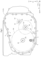
以下、本発明の実施形態を図面に基づいて説明する。図1及び図2に示すように、本実施形態に係る車両用駆動装置100は、車輪Wの駆動力源である回転電機MGと、車輪Wに駆動連結される出力部材OUTと、回転電機MGと出力部材OUTとを駆動連結するギヤ機構TAと、回転電機MG及びギヤ機構TAを収容するケース10とを備えている。図1に示すように、ケース10は、ケース10の区画壁部4により区画された第1収容室1と第2収容室2とを少なくとも備えている。後述するように、本実施形態では、第1収容室1に回転電機MGが収容され、第2収容室2にギヤ機構TAが収容されている。また、本実施形態では、ケース10は、第1収容室1及び第2収容室2に対して周壁部11aにより区画された第3収容室3も備えている。第3収容室3には、回転電機MGを駆動制御するインバータINVが収容されている。
Hereinafter, embodiments of the present invention will be described based on the drawings. As shown in FIGS. 1 and 2, the vehicle drive device 100 according to the present embodiment includes a rotating electrical machine MG as a driving force source for wheels W, an output member OUT drivingly connected to the wheels W, and a rotating electrical machine MG. and an output member OUT, and a case 10 that accommodates the rotary electric machine MG and the gear mechanism TA. As shown in FIG. 1 , the case 10 includes at least a first storage chamber 1 and a second storage chamber 2 partitioned by a partition wall portion 4 of the case 10 . As will be described later, in the present embodiment, the rotating electric machine MG is accommodated in the first accommodation chamber 1 and the gear mechanism TA is accommodated in the second accommodation chamber 2 . In this embodiment, the case 10 also includes a third storage chamber 3 that is partitioned from the first storage chamber 1 and the second storage chamber 2 by the peripheral wall portion 11a. The third accommodation chamber 3 accommodates an inverter INV that drives and controls the rotary electric machine MG.
図1及び図2に示すように、回転電機MGは第1軸A1上に配置され、出力部材OUTは第1軸A1と互いに平行な別軸である第2軸A2上に配置されている。ギヤ機構TAは、回転電機MGと出力部材OUTとの間の動力伝達経路に設けられて、回転電機MGと出力部材OUTとを駆動連結する複数のギヤGを備えて構成されている。複数のギヤGには、後述するカウンタギヤ機構CGを構成するギヤGも含まれる。カウンタギヤ機構CGは、第1軸A1及び第2軸A2と互いに平行な別軸である第3軸A3上に配置されている。また、ギヤ機構TAは、回転電機MGから複数のギヤGを介して伝達される駆動力を一対の車輪Wに分配する差動歯車機構DFも含む。詳細は、後述するが、この差動歯車機構DFの一対の出力ギヤ(サイドギヤSG)が出力部材OUTに相当する。本実施形態では、車輪Wと出力部材OUTとが、出力軸DSを介して連結されている。この出力軸DSを出力部材OUTと考えることもできる。また、差動歯車機構DFの一対のサイドギヤSGは、出力部材OUTに相当すると共に、ギヤ機構TAに含まれると考えることもできる。
As shown in FIGS. 1 and 2, the rotating electric machine MG is arranged on the first axis A1, and the output member OUT is arranged on the second axis A2 parallel to the first axis A1. The gear mechanism TA is provided in a power transmission path between the rotating electrical machine MG and the output member OUT, and includes a plurality of gears G for drivingly connecting the rotating electrical machine MG and the output member OUT. The plurality of gears G also include a gear G that constitutes a counter gear mechanism CG, which will be described later. The counter gear mechanism CG is arranged on a third axis A3 which is parallel to the first axis A1 and the second axis A2. The gear mechanism TA also includes a differential gear mechanism DF that distributes the driving force transmitted from the rotary electric machine MG via the gears G to the pair of wheels W. As shown in FIG. Although the details will be described later, the pair of output gears (side gears SG) of the differential gear mechanism DF correspond to the output member OUT. In this embodiment, the wheel W and the output member OUT are connected via the output shaft DS. This output shaft DS can also be considered as an output member OUT. Also, the pair of side gears SG of the differential gear mechanism DF correspond to the output member OUT and can also be considered to be included in the gear mechanism TA.
尚、本願において「駆動連結」とは、2つの回転要素が駆動力を伝達可能に連結された状態を指し、当該2つの回転要素が一体的に回転するように連結された状態、或いは当該2つの回転要素が1つ又は2つ以上の伝動部材を介して駆動力を伝達可能に連結された状態を含む。このような伝動部材としては、回転を同速で又は変速して伝達する各種の部材、例えば、軸、歯車機構、ベルト、チェーン等が含まれる。なお、伝動部材として、回転及び駆動力を選択的に伝達する係合装置、例えば、摩擦係合装置、噛み合い式係合装置等が含まれていても良い。
In the present application, "driving connection" refers to a state in which two rotating elements are connected so as to be able to transmit driving force, and the two rotating elements are connected so as to rotate integrally, or the two rotating elements It includes a state in which two rotating elements are connected so as to be able to transmit driving force via one or more transmission members. Such transmission members include various members that transmit rotation at the same speed or at different speeds, such as shafts, gear mechanisms, belts, and chains. The transmission member may include an engagement device for selectively transmitting rotation and driving force, such as a friction engagement device and a mesh type engagement device.
詳細は後述するが、図1に示すように、回転電機MGのロータRtには、ロータRtと一体回転するように、入力ギヤG1が連結されている。本実施形態では、入力ギヤG1は、ロータRtのロータ軸RSと一体回転するようにロータ軸RSに連結された入力軸ISの外周側に、入力軸ISと一体的に形成されている。ギヤ機構TAを構成する複数のギヤGには、入力ギヤG1も含まれる。
Although the details will be described later, as shown in FIG. 1, an input gear G1 is connected to the rotor Rt of the rotary electric machine MG so as to rotate integrally with the rotor Rt. In this embodiment, the input gear G1 is formed integrally with the input shaft IS on the outer peripheral side of the input shaft IS which is connected to the rotor shaft RS of the rotor Rt so as to rotate integrally with the rotor shaft RS. An input gear G1 is also included in the plurality of gears G that constitute the gear mechanism TA.
第1軸A1、第2軸A2及び第3軸A3は、互いに異なる仮想軸であり、上述したように互いに平行に配置されている。以下の説明においては、第1軸A1に平行な方向を軸方向Lとする。第1軸A1と第2軸A2とは互いに平行であるから、軸方向Lは第2軸A2にも平行な方向である。また、第3軸A3も、第1軸A1及び第2軸A2と互いに平行であるから、軸方向Lは第3軸A3にも平行な方向である。軸方向Lにおける一方側(本実施形態では、ギヤ機構TAに対して回転電機MGが配置される側)を「軸方向第1側L1」とし、その反対側を「軸方向第2側L2」とする。
The first axis A1, the second axis A2 and the third axis A3 are virtual axes different from each other, and are arranged parallel to each other as described above. In the following description, the axial direction L is the direction parallel to the first axis A1. Since the first axis A1 and the second axis A2 are parallel to each other, the axial direction L is also parallel to the second axis A2. Further, since the third axis A3 is also parallel to the first axis A1 and the second axis A2, the axial direction L is also parallel to the third axis A3. One side in the axial direction L (in this embodiment, the side on which the rotary electric machine MG is arranged with respect to the gear mechanism TA) is defined as the "first axial side L1", and the opposite side is defined as the "second axial side L2". and
また、上記の第1軸A1、第2軸A2、及び第3軸A3のそれぞれに直交する方向を、各軸を基準とした「径方向R」とする。尚、どの軸を基準とするかを区別する必要がない場合やどの軸を基準とするかが明らかである場合には、単に「径方向R」と記す場合がある。また、車両用駆動装置100が車両に取り付けられた状態で鉛直方向に沿う方向を「上下方向V」とする。また、本実施形態では、上下方向Vの一方側である上下方向第1側V1が上方であり、他方側である上下方向第2側V2が下方である。水平面に平行な状態で車両用駆動装置100が車両に取り付けられる場合には、径方向Rの1方向と上下方向Vとが一致する。
Also, the direction orthogonal to each of the first axis A1, second axis A2, and third axis A3 is defined as "radial direction R" with respect to each axis. When there is no need to distinguish which axis should be used as a reference, or when it is clear which axis should be used as a reference, the term "radial direction R" may simply be used. Further, the direction along the vertical direction with the vehicle drive device 100 attached to the vehicle is defined as the "vertical direction V". Further, in the present embodiment, the first vertical side V1, which is one side in the vertical direction V, is upward, and the second vertical side V2, which is the other side, is downward. When the vehicle drive device 100 is attached to the vehicle in parallel with the horizontal plane, one direction of the radial direction R and the vertical direction V coincide with each other.
また、軸方向L及び上下方向Vに直交する方向を「幅方向H」と称する。また、幅方向Hの一方側を幅方向第1側H1、他方側を幅方向第2側H2と称する。上下方向Vと同様に、径方向Rの1方向と幅方向Hとも一致する。尚、以下の説明では、各部材についての方向や位置等に関する用語は、製造上許容され得る誤差による差異を有する状態をも含む概念である。また、各部材についての方向は、それらが車両用駆動装置100に組み付けられた状態での方向を表す。本実施形態では、幅方向Hは、車両用駆動装置100が車両に取り付けられた状態での車両の前後方向に相当する。
Also, the direction perpendicular to the axial direction L and the vertical direction V is referred to as the "width direction H". In addition, one side in the width direction H is called a width direction first side H1, and the other side is called a width direction second side H2. As with the vertical direction V, one direction of the radial direction R and the width direction H also coincide. In the following description, terms relating to the direction, position, etc. of each member are concepts that include the state of having a difference due to an allowable manufacturing error. Also, the direction of each member represents the direction when they are assembled in the vehicle drive system 100 . In the present embodiment, the width direction H corresponds to the longitudinal direction of the vehicle when the vehicle drive system 100 is attached to the vehicle.
本実施形態では、ケース10は、第1収容室1と第2収容室2と第3収容室3とを形成するように一体成形されたケース本体部11を備えている。ここで、「一体成形」とは、例えば1つの金型鋳造品(die casting)として、共通の材料により形成された一体部材のことを言う。当然ながら、ケース本体部11は複数の部材によって構成されていてもよい。また、ケース10は、ケース本体部11に加えて、軸方向第1側L1からケース本体部11に接合される第1カバー10aと、軸方向第2側L2からケース本体部11に接合される第2カバー10bと、上下方向第1側V1からケース本体部11に接合される第3カバー10cとを備えている。第3収容室3は、概ね第1収容室1よりも軸方向第2側L2、及び第2収容室2よりも上下方向第1側V1において、第1収容室1及び第2収容室2に対して区画された空間として形成されている。
In this embodiment, the case 10 includes a case main body 11 integrally formed to form the first storage chamber 1 , the second storage chamber 2 and the third storage chamber 3 . As used herein, "integrally molded" refers to a unitary member formed of a common material, for example, as a single die casting. As a matter of course, the case main body 11 may be composed of a plurality of members. In addition to the case main body portion 11, the case 10 includes a first cover 10a that is joined to the case main body portion 11 from the first axial side L1, and a first cover 10a that is joined to the case main body portion 11 from the second axial side L2. It has a second cover 10b and a third cover 10c joined to the case main body 11 from the first vertical side V1. The third storage chamber 3 is positioned between the first storage chamber 1 and the second storage chamber 2 on the second side L2 in the axial direction from the first storage chamber 1 and on the first side V1 in the vertical direction from the second storage chamber 2. It is formed as a space partitioned against.
ケース10、具体的には筒状のケース本体部11の内部には、上下方向V及び幅方向Hに沿って延在し、第1収容室1と第2収容室2とを区画する区画壁部4が形成されている(図1、図3、図8等参照)。区画壁部4は、第1収容室1と第2収容室2とを軸方向Lに区画している。第1収容室1は、ケース本体部11と、第1カバー10aと、区画壁部4とに囲われた空間として形成されている。第2収容室2は、ケース本体部11と、第2カバー10bと、区画壁部4とに囲われた空間として形成されている。第3収容室3は、筒状のケース本体部11における第2収容室2よりも上下方向第1側V1の周壁部11aと、周壁部11aから上下方向第1側V1に立設された側壁部11bと、第3カバー10cとに囲まれた空間として形成されている。
Inside the case 10, specifically, the cylindrical case main body 11, there is a partition wall extending along the vertical direction V and the width direction H to partition the first storage chamber 1 and the second storage chamber 2. A portion 4 is formed (see FIGS. 1, 3, 8, etc.). The partition wall 4 partitions the first storage chamber 1 and the second storage chamber 2 in the axial direction L. As shown in FIG. The first storage chamber 1 is formed as a space surrounded by the case body 11 , the first cover 10 a and the partition wall 4 . The second storage chamber 2 is formed as a space surrounded by the case main body 11 , the second cover 10 b and the partition wall 4 . The third storage chamber 3 includes a peripheral wall portion 11a on the first vertical side V1 of the cylindrical case main body portion 11 relative to the second storage chamber 2, and a side wall erected on the first vertical side V1 from the peripheral wall portion 11a. It is formed as a space surrounded by the portion 11b and the third cover 10c.
回転電機MGは、複数相の交流(例えば3相交流)により動作する回転電機(Motor/Generator)であり、電動機としても発電機としても機能することができる。回転電機MGは、不図示の直流電源から電力の供給を受けて力行し、又は、車両の慣性力により発電した電力を直流電源に供給する(回生する)。図1に示すように、回転電機MGは、ケース10に固定されたステータStと、当該ステータStの径方向Rの内側に回転可能に支持されたロータRtとを有する。ステータStは、ステータコアとステータコアに巻き回されたステータコイルScとを含み、ロータRtは、ロータコアとロータコアに配置された永久磁石とを含む。
The rotating electrical machine MG is a rotating electrical machine (Motor/Generator) that operates with multi-phase alternating current (for example, 3-phase alternating current), and can function as both a motor and a generator. The rotary electric machine MG is powered by being supplied with power from a DC power supply (not shown), or supplies (regenerates) power generated by the inertial force of the vehicle to the DC power supply. As shown in FIG. 1, the rotary electric machine MG has a stator St fixed to the case 10 and a rotor Rt rotatably supported inside the stator St in the radial direction R. The stator St includes a stator core and a stator coil Sc wound around the stator core, and the rotor Rt includes a rotor core and permanent magnets arranged in the rotor core.
回転電機MGのロータRtはロータ軸RSに連結され、ロータ軸RSは入力軸ISに連結され、入力軸ISには径方向Rの外側に入力ギヤG1が一体的に形成されている。当然ながら、入力ギヤG1は入力軸ISとは別部材によって形成されて入力軸ISに連結されていてもよい。即ち、ロータRtは、ロータ軸RS、入力軸ISを介して入力ギヤG1に駆動連結されており、入力ギヤG1はロータRtと一体的に回転する。後述するように、入力ギヤG1は、カウンタギヤ機構CGに駆動連結されている。ロータ軸RSは一対の第1軸受B1によりケース10に対して回転可能に支持され、入力軸ISは一対の第2軸受B2によりケース10に対して回転可能に支持されている。一対の第1軸受B1は、第1カバー10a及び区画壁部4によりそれぞれ支持されている。一対の第2軸受B2は、区画壁部4及び第2カバー10bによりそれぞれ支持されている。
A rotor Rt of the rotary electric machine MG is connected to a rotor shaft RS, the rotor shaft RS is connected to an input shaft IS, and an input gear G1 is formed integrally with the input shaft IS on the outside in the radial direction R. Of course, the input gear G1 may be formed of a member separate from the input shaft IS and connected to the input shaft IS. That is, the rotor Rt is drivingly connected to the input gear G1 via the rotor shaft RS and the input shaft IS, and the input gear G1 rotates integrally with the rotor Rt. As will be described later, the input gear G1 is drivingly connected to the counter gear mechanism CG. The rotor shaft RS is rotatably supported with respect to the case 10 by a pair of first bearings B1, and the input shaft IS is rotatably supported with respect to the case 10 by a pair of second bearings B2. The pair of first bearings B1 are supported by the first cover 10a and the partition wall portion 4, respectively. The pair of second bearings B2 are respectively supported by the partition wall portion 4 and the second cover 10b.
カウンタギヤ機構CGは、第1軸A1及び第2軸A2と平行な第3軸A3上に配置され、入力ギヤG1を介して回転電機MGと差動歯車機構DFとを駆動連結している。本実施形態では、カウンタギヤ機構CGは、軸部材(カウンタ軸CS)によって連結された2つのギヤ(第1カウンタギヤG2、第2カウンタギヤG3)を有する。即ち、カウンタギヤ機構CGは、第3軸A3上に配置され、入力ギヤG1に噛み合う第1カウンタギヤG2と、この第1カウンタギヤG2と一体的に回転すると共に、後述する差動歯車機構DFの差動入力ギヤG4に噛み合う第2カウンタギヤG3とを備えている。カウンタ軸CSは、一対の第3軸受B3によってケース10に対して回転可能に支持されている。第3軸受B3は、区画壁部4及び第2カバー10bによりそれぞれ支持されている。
The counter gear mechanism CG is arranged on a third axis A3 parallel to the first axis A1 and the second axis A2, and drivingly connects the rotary electric machine MG and the differential gear mechanism DF via the input gear G1. In this embodiment, the counter gear mechanism CG has two gears (first counter gear G2, second counter gear G3) connected by a shaft member (counter shaft CS). That is, the counter gear mechanism CG includes a first counter gear G2 arranged on the third shaft A3 and meshing with the input gear G1, and a differential gear mechanism DF which rotates integrally with the first counter gear G2. and a second counter gear G3 that meshes with the differential input gear G4. The counter shaft CS is rotatably supported with respect to the case 10 by a pair of third bearings B3. The third bearing B3 is supported by the partition wall portion 4 and the second cover 10b.
差動歯車機構DFは、差動ケースDCと、一対のピニオンギヤPGと、一対のサイドギヤSGとを備えている。一対のピニオンギヤPG及び一対のサイドギヤSGは、いずれも傘歯車であり、本実施形態の差動歯車機構DFは傘歯車式の差動歯車機構である。当然ながら、差動歯車機構DFは、これとは別の構成、例えば遊星歯車式の差動歯車機構であってもよい。差動ケースDCは、一対のピニオンギヤPG及び一対のサイドギヤSGを収容する中空の部材である。本実施形態では、差動ケースDCは、一対の第4軸受B4により、ケース10に対して回転可能に支持されている。本実施形態では、一対の第4軸受B4は、区画壁部4及び第2カバー10bによりそれぞれ支持されている。
The differential gear mechanism DF includes a differential case DC, a pair of pinion gears PG, and a pair of side gears SG. The pair of pinion gears PG and the pair of side gears SG are both bevel gears, and the differential gear mechanism DF of the present embodiment is a bevel gear type differential gear mechanism. Of course, the differential gear mechanism DF may also have a different configuration, for example a planetary gear differential gear mechanism. The differential case DC is a hollow member that houses a pair of pinion gears PG and a pair of side gears SG. In this embodiment, the differential case DC is rotatably supported with respect to the case 10 by a pair of fourth bearings B4. In this embodiment, the pair of fourth bearings B4 are respectively supported by the partition wall portion 4 and the second cover 10b.
差動ケースDCと差動入力ギヤG4とは、一体的に回転するように連結されている。一対のピニオンギヤPGは、第2軸A2を基準とした径方向Rに間隔を空けて、互いに対向するように配置されている。差動ケースDCには、差動ケースDCと一体的に回転するようにピニオンシャフトPSが支持されており、一対のピニオンギヤPGは、ピニオンシャフトPSに取り付けられている。一対のピニオンギヤPGのそれぞれは、ピニオンシャフトPSを中心として回転(自転)可能、かつ、第2軸A2を中心として回転(公転)可能である。一対のピニオンギヤPGには一対のサイドギヤSGが噛み合っている。一対のサイドギヤSGは、第2軸A2を回転軸心として回転するように、互いに軸方向Lに間隔を空けて、ピニオンシャフトPSを挟んで対向するように配置されている。
The differential case DC and the differential input gear G4 are connected so as to rotate integrally. The pair of pinion gears PG are arranged to face each other with a gap in the radial direction R with respect to the second axis A2. A pinion shaft PS is supported by the differential case DC so as to rotate integrally with the differential case DC, and a pair of pinion gears PG are attached to the pinion shaft PS. Each of the pair of pinion gears PG is rotatable (rotating) about the pinion shaft PS and rotatable (revolving) about the second axis A2. A pair of side gears SG are in mesh with the pair of pinion gears PG. The pair of side gears SG are arranged to face each other across the pinion shaft PS with a gap in the axial direction L so as to rotate about the second axis A2.
それぞれのサイドギヤSGは、一対の出力軸DSのそれぞれに駆動連結され、それぞれの出力軸DSは一対の車輪Wにそれぞれ駆動連結されている。本実施形態では、一対のサイドギヤSGの一方である第1サイドギヤS1が連結軸JTに連結され、連結軸JTが一対の出力軸DSの一方である第1出力軸DS1に連結され、第1出力軸DS1が一対の車輪Wの内の一方に連結されている。連結軸JTは、一端側において第1サイドギヤS1と一体的に回転するように連結され、第1収容室1内を軸方向Lに延在して、他端側において第1収容室1を形成する第1カバー10aに支持された第5軸受B5によってケース10に対して回転可能に支持されている。第1出力軸DS1は、一端側が連結軸JTと一体的に回転するように連結され、他端側は車両内の不図示の部材により支持されている。第1出力軸DS1の他端側には、第1カバー10aに支持された第1シール部材B6が備えられている。一対のサイドギヤSGの他方である第2サイドギヤS2は、一対の出力軸DSの他方である第2出力軸DS2に連結され、第2出力軸DS2が一対の車輪Wの内の他方に連結されている。第2出力軸DS2は、一端側において第2サイドギヤS2と一体的に回転するように連結され、他端側は車両内の不図示の部材により支持されている。第2出力軸DS2の他端側には、第2収容室2を形成する第2カバー10bに支持された第2シール部材B7が備えられている。
Each side gear SG is drivingly connected to a pair of output shafts DS, respectively, and each output shaft DS is drivingly connected to a pair of wheels W, respectively. In this embodiment, the first side gear S1, which is one of the pair of side gears SG, is connected to the connecting shaft JT, and the connecting shaft JT is connected to the first output shaft DS1, which is one of the pair of output shafts DS. A shaft DS1 is connected to one of a pair of wheels W. As shown in FIG. The connecting shaft JT is connected to rotate integrally with the first side gear S1 at one end side, extends in the axial direction L within the first housing chamber 1, and forms the first housing chamber 1 at the other end side. It is rotatably supported with respect to the case 10 by the fifth bearing B5 supported by the first cover 10a. One end of the first output shaft DS1 is connected to the connecting shaft JT so as to rotate integrally, and the other end is supported by a member (not shown) inside the vehicle. A first seal member B6 supported by the first cover 10a is provided on the other end side of the first output shaft DS1. A second side gear S2, which is the other of the pair of side gears SG, is connected to a second output shaft DS2, which is the other of the pair of output shafts DS, and the second output shaft DS2 is connected to the other of the pair of wheels W. there is One end of the second output shaft DS2 is connected to rotate integrally with the second side gear S2, and the other end is supported by a member (not shown) inside the vehicle. A second seal member B7 supported by a second cover 10b forming the second housing chamber 2 is provided on the other end side of the second output shaft DS2.
このように差動歯車機構DFは、ロータRtから、入力ギヤG1、カウンタギヤ機構CG(第1カウンタギヤG2、第2カウンタギヤG3)、差動入力ギヤG4を介して伝達されたトルクを出力部材OUTとしての一対のサイドギヤSGに分配し、一対の車輪Wに駆動力を伝達する。これにより、車両用駆動装置100は、回転電機MGのトルクを車輪Wに伝達させて車両を走行させることができる。尚、サイドギヤSG、出力軸DSの他、連結軸JTを出力部材OUTと考えることもできる。
Thus, the differential gear mechanism DF outputs torque transmitted from the rotor Rt via the input gear G1, the counter gear mechanism CG (first counter gear G2, second counter gear G3), and the differential input gear G4. The driving force is distributed to a pair of side gears SG as members OUT and transmitted to a pair of wheels W. Accordingly, the vehicle drive device 100 can transmit the torque of the rotary electric machine MG to the wheels W to drive the vehicle. In addition to the side gear SG and the output shaft DS, the connecting shaft JT can also be considered as the output member OUT.
ところで、車両用駆動装置100を構成する回転電機MG、ギヤ機構TAは、油によって潤滑されている(冷却も含む)。具体的には、上述したそれぞれの軸受(B1~B5)、シール部材(B6,B7)、回転電機MGのステータコイルScなど(潤滑対象箇所と総称する)が油によって潤滑・冷却される。潤滑用の油は、車輪Wの駆動力源(上述した回転電機MG、別途内燃機関等を備える場合には内燃機関も含む)の1つ以上を駆動力源として駆動される不図示の機械式オイルポンプ、並びに、車輪Wの駆動力源とは別の駆動力源(例えば回転電機MGとは別の回転電機(モータ))により駆動される不図示の電動オイルポンプの少なくとも一方から車両用駆動装置100に供給される。車両用駆動装置100には、潤滑対象箇所への油路が形成され、これらのオイルポンプからの油が供給される。但し、全ての潤滑対象箇所に対してオイルポンプからの油路を形成すると、油路が複雑化し、車両用駆動装置100が大型化する可能性がある。また、油路が多くなると、オイルポンプの吐出能力を高くする必要が生じる場合がある。
By the way, the rotary electric machine MG and the gear mechanism TA that constitute the vehicle drive device 100 are lubricated with oil (including cooling). Specifically, the bearings (B1 to B5), the seal members (B6, B7), the stator coil Sc of the rotary electric machine MG, and the like (generically referred to as lubrication target locations) are lubricated and cooled by oil. The lubricating oil is a mechanical type (not shown) that is driven by one or more of the driving force sources of the wheels W (including the above-described rotating electrical machine MG and an internal combustion engine if a separate internal combustion engine is provided). Vehicle driving from at least one of an oil pump and an electric oil pump (not shown) driven by a driving force source different from the driving force source of the wheels W (for example, a rotating electric machine (motor) different from the rotating electric machine MG) supplied to the device 100 . The vehicle drive system 100 is formed with oil passages to lubrication target locations, and oil is supplied from these oil pumps. However, if the oil passages from the oil pump are formed for all lubrication target locations, the oil passages may become complicated and the vehicle drive device 100 may become large. Further, when the number of oil passages increases, it may be necessary to increase the discharge capacity of the oil pump.
そこで、オイルポンプから直接的に油を供給するだけではなく、車両用駆動装置100の一部の潤滑対象箇所(例えば本実施形態では回転電機MGのステータコイルSc)に対してはオイルポンプから油を供給し、当該潤滑対象箇所を潤滑した後の油を使って他の潤滑対象箇所(例えば本実施形態ではギヤGや軸受(B1~B5))を潤滑することがしばしば行われる。潤滑に用いられた油は重力よって落下し、ケース10内(ケース10の底部に位置する油溜まり)に貯留される。そして、例えば、車両用駆動装置100が備える各種のギヤGなどの回転部材により、当該油溜まりの油を掻き上げたり、ギヤG等の回転部材に降りかかる油を遠心力によって飛ばしたりすることによって、他の潤滑対象箇所を潤滑するように構成される場合がある。本実施形態では、ケース10の底部の油溜まりから油を掻き上げる回転部材として、第1カウンタギヤG2や差動入力ギヤG4が用いられる。本実施形態では、歯面が最も上下方向第2側V2に位置する差動入力ギヤG4が主として掻き上げ用のギヤGとして機能する。即ち、ギヤ機構TAは、ケース10の内部の油を掻き上げることで潤滑対象箇所へ油を供給する。本実施形態において、ギヤ機構TA(ここでは主として差動入力ギヤG4)の掻き上げによる潤滑対象箇所は、ギヤ機構TAを構成する各ギヤG、軸受(B1~B5)である。
Therefore, in addition to supplying oil directly from the oil pump, oil is supplied from the oil pump to a portion of the vehicle drive device 100 (for example, the stator coil Sc of the rotary electric machine MG in this embodiment) to be lubricated. is supplied, and lubrication of other lubrication target locations (eg, gear G and bearings (B1 to B5) in this embodiment) is often performed using the oil after lubricating the lubrication target location. The oil used for lubrication drops due to gravity and is stored in the case 10 (an oil reservoir located at the bottom of the case 10). Then, for example, by using a rotating member such as various gears G provided in the vehicle drive device 100 to rake up the oil in the oil pool, or by using a centrifugal force to blow off the oil falling on the rotating member such as the gear G, It may be configured to lubricate other locations to be lubricated. In this embodiment, the first counter gear G2 and the differential input gear G4 are used as rotating members for raking up the oil from the oil pool on the bottom of the case 10 . In the present embodiment, the differential input gear G4 whose tooth surface is positioned closest to the second side V2 in the vertical direction mainly functions as the gear G for scraping. That is, the gear mechanism TA rakes up the oil inside the case 10 to supply the oil to the lubrication target location. In this embodiment, the parts to be lubricated by raking of the gear mechanism TA (here, mainly the differential input gear G4) are the gears G and bearings (B1 to B5) constituting the gear mechanism TA.
上述したように、本実施形態では、潤滑対象箇所は、第1収容室1及び第2収容室2の双方に存在する。従って、潤滑後の油は、第1収容室1及び第2収容室2の中で落下しそれぞれの底部に溜まる。掻き上げ用のギヤGは上述したように第2収容室2に配置されている。また、第1収容室1にはオイルポンプが配置されている場合がある。従って、両収容室に適切に油が溜まることが好ましい。このため、第1収容室1と第2収容室2との間で油が通流可能なように、第1収容室1と第2収容室2とを区画する区画壁部4には、図3等に示すように、第1収容室1と第2収容室2とを連通する開口部5が形成されている。そして、この開口部5には、図3から図8に示すように、第1収容室1から第2収容室2への油の流れを許容し、第2収容室2から第1収容室1への油の流れを規制するように弁体6が取り付けられている。
As described above, in this embodiment, lubrication target locations exist in both the first storage chamber 1 and the second storage chamber 2 . Therefore, the lubricated oil drops in the first storage chamber 1 and the second storage chamber 2 and accumulates at the bottom of each. The raking gear G is arranged in the second storage chamber 2 as described above. Also, an oil pump may be arranged in the first housing chamber 1 . Therefore, it is preferable that both storage chambers are appropriately filled with oil. For this reason, the partition wall portion 4 that partitions the first storage chamber 1 and the second storage chamber 2 so that the oil can flow between the first storage chamber 1 and the second storage chamber 2 has a As shown in 3 and the like, an opening 5 that communicates the first storage chamber 1 and the second storage chamber 2 is formed. As shown in FIGS. 3 to 8, the opening 5 allows oil to flow from the first storage chamber 1 to the second storage chamber 2, and allows oil to flow from the second storage chamber 2 to the first storage chamber 1. A valve body 6 is attached so as to regulate the flow of oil to.
弁体6は、図4に示すように、プレート61と、固定部62と、蝶番部63と、錐状部64とを備えている、プレート61と固定部62とは、蝶番部63を介して相対的に揺動可能に連結されている。固定部62は、第2収容室2の側から締結部材69により区画壁部4に固定される。従って、弁体6は、固定部62及び蝶番部63が区画壁部4の第2収容室2の側の面(取り付け面42)に固定された状態で、プレート61が揺動するように、区画壁部4に取り付けられている。プレート61は、開口部5よりも大きな面積を有しており、プレート61の中央部に錐状部64が形成されている。錐状部64は、弁体6が区画壁部4に取り付けられた状態で第1収容室1の側に突出する(プレート61における中央部を囲む部分に対して突出する)ように形成されている。
As shown in FIG. 4, the valve body 6 includes a plate 61, a fixed portion 62, a hinge portion 63, and a conical portion 64. are connected to each other so as to be able to swing relative to each other. The fixed portion 62 is fixed to the partition wall portion 4 by a fastening member 69 from the second storage chamber 2 side. Therefore, the valve body 6 is arranged such that the plate 61 swings while the fixing portion 62 and the hinge portion 63 are fixed to the surface (mounting surface 42) of the partition wall portion 4 on the side of the second housing chamber 2. It is attached to the partition wall portion 4 . The plate 61 has an area larger than that of the opening 5, and a conical portion 64 is formed in the central portion of the plate 61. As shown in FIG. The conical portion 64 is formed to protrude toward the first housing chamber 1 side (protrudes to the portion of the plate 61 surrounding the central portion) with the valve body 6 attached to the partition wall portion 4 . there is
図5に示すように、弁体6は、車両が傾いておらず水平状態であるとき、即ち車両用駆動装置100が水平姿勢であるとき、プレート61が区画壁部4から離れる姿勢(第1姿勢P1)となるように構成されている。弁体6が第1姿勢P1であるときには、図5に示すように開口部5は弁体6(プレート61及び錐状部64)によって塞がれることなく、油は、第1収容室1と第2収容室2との間で、自在に流通することができる。つまり、第1収容室1と第2収容室2との間で、双方向の油の流れが許容される。
As shown in FIG. 5, the valve body 6 is in a posture (first It is configured to take the posture P1). When the valve body 6 is in the first posture P1, as shown in FIG. It can be freely circulated to and from the second storage chamber 2 . In other words, bidirectional oil flow is allowed between the first storage chamber 1 and the second storage chamber 2 .
一方、プレート61が区画壁部4に接している姿勢(第2姿勢P2)では、図5に破線で示すように、開口部5は弁体6(プレート61及び錐状部64)によって塞がれる。ここで、第2収容室2から第1収容室1へ油が流れようとした場合、流体圧によってプレート61が区画壁部4の方向に押圧されるため、第2収容室2から第1収容室1への油の流れは、弁体6によって遮断される。第1収容室1から第2収容室2へ油が流れようとした場合には、流体圧によってプレート61が区画壁部4から離れる方向に押圧されるため、流体圧がプレート61を区画壁部4に押しつける力を上回ると開口部5は開放される。従って、第1収容室1から第2収容室2への油の流れは、弁体6によって遮断されることなく、油が流通する。本実施形態では、第1姿勢P1と第2姿勢P2との間の角度(開き角θ)は5~10度程度である。
On the other hand, in the posture (second posture P2) in which the plate 61 is in contact with the partition wall portion 4, the opening portion 5 is closed by the valve body 6 (the plate 61 and the conical portion 64), as indicated by the broken line in FIG. be Here, when the oil tries to flow from the second storage chamber 2 to the first storage chamber 1, the fluid pressure presses the plate 61 in the direction of the partition wall portion 4, so that the flow from the second storage chamber 2 to the first storage chamber 2 is prevented. Oil flow to chamber 1 is blocked by valve body 6 . When the oil tries to flow from the first storage chamber 1 to the second storage chamber 2, the plate 61 is pushed away from the partition wall 4 by the fluid pressure. The opening 5 is opened when the force pressing against 4 is exceeded. Therefore, the oil flows from the first storage chamber 1 to the second storage chamber 2 without being blocked by the valve body 6 . In this embodiment, the angle (opening angle θ) between the first attitude P1 and the second attitude P2 is about 5 to 10 degrees.
ところで、上述したように、車両用駆動装置100における潤滑対象箇所は、第1収容室1及び第2収容室2の双方に存在する。例えば、ケース10の底部の油溜まり、特に第2収容室2の底部の油溜まりから、差動入力ギヤG4によって油を掻き上げることで、不図示のキャッチタンクや油路を介して、入力ギヤG1、第1カウンタギヤG2、第2カウンタギヤG3、第1軸受B1、第2軸受B2、第3軸受B3、第4軸受B4、第5軸受B5、第1シール部材B6、第2シール部材B7等を潤滑することができる。また、同様に、不図示のキャッチタンクや油路を介して、回転電機MGのステータコイルScを冷却することができる。例えば第1軸受B1を潤滑した油、ステータコイルScを冷却した油は、第1収容室1内に落下し、第1収容室1の底部の油溜まりに貯留される。そして、区画壁部4の開口部5を介して、第1収容室1に貯留された油は第2収容室2の油溜まりへと流れる。このようにケース10内を油が循環することで、回転電機MG及びギヤ機構TAが適切に潤滑され続ける。
By the way, as described above, the locations to be lubricated in the vehicle drive device 100 are present in both the first accommodation chamber 1 and the second accommodation chamber 2 . For example, by raking up oil from the oil pool at the bottom of the case 10, especially from the oil pool at the bottom of the second storage chamber 2, by the differential input gear G4, the input gear G1, first counter gear G2, second counter gear G3, first bearing B1, second bearing B2, third bearing B3, fourth bearing B4, fifth bearing B5, first sealing member B6, second sealing member B7 etc. can be lubricated. Similarly, the stator coil Sc of the rotary electric machine MG can be cooled via a catch tank and an oil passage (not shown). For example, oil that lubricates the first bearing B1 and oil that cools the stator coil Sc drops into the first storage chamber 1 and is stored in an oil reservoir at the bottom of the first storage chamber 1 . The oil stored in the first storage chamber 1 flows into the oil reservoir of the second storage chamber 2 through the opening 5 of the partition wall 4 . By circulating the oil in the case 10 in this way, the rotary electric machine MG and the gear mechanism TA continue to be appropriately lubricated.
但し、このように2つの収容室の間で油が通流可能な場合、車両の傾きや、車両の旋回や加速度等に伴う慣性力によって何れかの収容室に油が偏ることがある。例えば、図7に示すように、第1収容室1の側に油が偏り第2収容室2の油が少なくなると、ギヤGによって掻き上げられる油が減少し、キャッチタンクや油路を介した潤滑対象箇所への油の供給が不十分となる場合がある。図7の例では、差動入力ギヤG4も第1カウンタギヤG2も、溜まった油LQの油面よりも上方に位置しており、掻き上げができない状態となっている。
However, when the oil can flow between the two storage chambers in this way, the oil may be biased in one of the storage chambers due to the inertia force associated with the inclination of the vehicle, turning, acceleration, etc. of the vehicle. For example, as shown in FIG. 7, when the oil is concentrated on the side of the first storage chamber 1 and the oil in the second storage chamber 2 decreases, the amount of oil raked up by the gear G decreases, and the oil flows through the catch tank and the oil passage. In some cases, the oil supply to the lubrication target location becomes insufficient. In the example of FIG. 7, both the differential input gear G4 and the first counter gear G2 are positioned above the level of the accumulated oil LQ, and are in a state in which they cannot rake up the oil.
しかし、本実施形態では、上述したように開口部5に弁体6を備えている。図6に示すように、車両用駆動装置100が軸方向第1側L1に傾いた場合、開口部5が弁体6によって塞がれる。これにより、第2収容室2から第1収容室1への油の流れが遮断され、第1収容室1に流出する油の量が抑制されて、ギヤGによる掻き上げに十分な油が第2収容室2にとどまる。図6に示す例では、差動入力ギヤG4の歯面の一部、第1カウンタギヤG2の歯面の全てが、第2収容室2に溜まった油LQに浸かっている。従って、図6に示す例では、差動入力ギヤG4及び第1カウンタギヤG2により油の掻き上げが可能である。
However, in this embodiment, the opening 5 is provided with the valve body 6 as described above. As shown in FIG. 6 , the opening 5 is closed by the valve body 6 when the vehicle drive device 100 is tilted toward the first side L1 in the axial direction. As a result, the flow of oil from the second storage chamber 2 to the first storage chamber 1 is blocked, the amount of oil flowing out to the first storage chamber 1 is suppressed, and the oil sufficient to be scraped up by the gear G is not supplied to the first storage chamber 1. 2 Stay in Containment Chamber 2. In the example shown in FIG. 6 , part of the tooth surface of the differential input gear G4 and all of the tooth surface of the first counter gear G2 are immersed in the oil LQ accumulated in the second housing chamber 2 . Therefore, in the example shown in FIG. 6, the differential input gear G4 and the first counter gear G2 can rake up the oil.
このように、第1収容室1と第2収容室2とを区画する区画壁部4に形成された開口部5に、第1収容室1から第2収容室2への油の流れを許容し、第2収容室2から第1収容室1への油の流れを規制するように弁体6が取り付けられていることで、車両の傾きや、旋回又は加減速による慣性力によって油面が傾いた場合であっても、第2収容室2の油面の低下を制限することができる。そして、第2収容室2の油面の低下が制限されることによって、ギヤGの掻き上げによって、潤滑対象箇所に適切に油を供給することができる。
In this manner, the opening 5 formed in the partition wall 4 that partitions the first storage chamber 1 and the second storage chamber 2 allows oil to flow from the first storage chamber 1 to the second storage chamber 2. However, since the valve body 6 is attached so as to restrict the flow of oil from the second storage chamber 2 to the first storage chamber 1, the oil level is lowered by inertial force due to inclination of the vehicle and turning or acceleration/deceleration. Even if it is tilted, it is possible to limit the lowering of the oil level in the second housing chamber 2 . Further, by restricting the lowering of the oil level in the second housing chamber 2, the gear G can rake up the oil to appropriately supply the lubrication target location.
上述したように、本実施形態では、第1収容室1に回転電機MGが収容され、第2収容室2にギヤ機構TAが収容されている。本実施形態によれば、車両の傾きや旋回又は加減速による慣性力によって油面が傾いた場合であっても、第2収容室2内の油面の低下が抑制される。例えば、第2収容室2に収容されるギヤ機構TAに含まれるギヤGの掻き上げによって、車両用駆動装置100の各部に潤滑(冷却)用の油が供給される場合、油面が当該ギヤGよりも低くなり、当該ギヤGによる油の掻き上げが妨げられることを抑制することができる。つまり、第2収容室2にギヤ機構TAが収容されているような構成において本実施形態の構成が適用されると、ギヤGによる油の掻き上げによって各部の潤滑を適切に行うことができる。
As described above, in the present embodiment, the rotating electrical machine MG is accommodated in the first accommodation chamber 1, and the gear mechanism TA is accommodated in the second accommodation chamber 2. According to the present embodiment, even when the oil level is tilted due to the inertial force due to tilting, turning, acceleration or deceleration of the vehicle, a decrease in the oil level in the second storage chamber 2 is suppressed. For example, when lubricating (cooling) oil is supplied to each part of the vehicle drive device 100 by raking up the gear G included in the gear mechanism TA housed in the second housing chamber 2, the oil surface of the gear is G, it is possible to prevent the gear G from impeding the raking up of the oil. That is, when the configuration of the present embodiment is applied to a configuration in which the gear mechanism TA is accommodated in the second accommodation chamber 2, the gear G can rake up the oil to properly lubricate each part.
尚、本実施形態では、車両用駆動装置100は、回転電機MGに油を供給する不図示のオイルポンプ(電動オイルポンプ)と、オイルポンプが吸引する油から不純物を取り除く不図示のストレーナとを備えている。ストレーナは、第2収容室2に収容されている。尚、オイルポンプも、第2収容室2に収容されている。図3及び図8に示すように、区画壁部4には、オイルポンプが吸入する油から不純物を取り除くストレーナが配置されるストレーナ配置孔9が形成されている。図示は省略しているが、このストレーナ配置孔9にも弁体が配置されてもよい。
In the present embodiment, the vehicle drive device 100 includes an oil pump (electric oil pump) (not shown) that supplies oil to the rotary electric machine MG, and a strainer (not shown) that removes impurities from the oil sucked by the oil pump. I have. The strainer is housed in the second housing chamber 2 . An oil pump is also housed in the second housing chamber 2 . As shown in FIGS. 3 and 8, the partition wall portion 4 is formed with a strainer arrangement hole 9 in which a strainer for removing impurities from the oil sucked by the oil pump is arranged. Although not shown, a valve body may be arranged in this strainer arrangement hole 9 as well.
ところで、ケース10の内部に貯留される油は、軸受の摩擦等によって生じる粉塵の混入や、ステータコイルScなどの高温部材に接したことによる組成の変化(例えば酸化)などにより劣化する。劣化を生じた油では、潤滑性能や冷却性能が低下することから、定期的にケース10内の油が交換される。この際、弁体6によって第1収容室1と第2収容室2との間の油の流れが制限される可能性を考慮して、第1収容室1に連通するドレン孔と、第2収容室2に連通するドレン孔とをそれぞれ設けるとケース10の構造が複雑化し、コストが上昇する場合がある。また、油を交換する際にも、2箇所から油を抜く作業が必要となり、工数が増加して整備コストが上昇する場合がある。
By the way, the oil stored inside the case 10 deteriorates due to contamination with dust caused by bearing friction and the like, and changes in composition (for example, oxidation) due to contact with high-temperature members such as the stator coil Sc. Since degraded oil deteriorates the lubricating performance and cooling performance, the oil in the case 10 is periodically replaced. At this time, considering the possibility that the flow of oil between the first storage chamber 1 and the second storage chamber 2 is restricted by the valve body 6, the drain hole communicating with the first storage chamber 1 and the second If a drain hole communicating with the housing chamber 2 is provided, the structure of the case 10 becomes complicated, and the cost may increase. Also, when replacing the oil, it is necessary to remove the oil from two locations, which may increase the number of man-hours and raise the maintenance cost.
このため、本実施形態では、図9に示すように、第1収容室1の底壁部21に、第1収容室1とケース10の外部とを連通するドレン孔7が形成されると共に、第2収容室2とドレン孔7とを連通する連通孔8を備えている。尚、ドレン孔7には、ドレンプラグ79が挿入されて着脱可能に固定される。このようなドレン孔7と連通孔8とを備えることにより、第1収容室1及び第2収容室2に収容された油を1つのドレン孔7から排出することができる。本実施形態のように、開口部5に弁体6が取り付けられていても、油を排出する際には、ドレン孔7と第2収容室2とを連通する連通孔8を介して、第2収容室2の油の排出が妨げられない。第1収容室1と第2収容室2とのそれぞれにドレン孔を設ける場合に比べて、ケース10の構造の簡略化と部品点数の削減を図ることができる。ドレン孔7はドレンプラグ79により塞がれているが、この1つのドレンプラグ79を抜くだけで第1収容室1と第2収容室2との双方の油を排出できるため、油を排出するための作業の効率も高めることができる。
Therefore, in this embodiment, as shown in FIG. 9, a drain hole 7 is formed in the bottom wall portion 21 of the first storage chamber 1 to communicate the first storage chamber 1 with the outside of the case 10. A communication hole 8 that communicates the second storage chamber 2 and the drain hole 7 is provided. A drain plug 79 is inserted into the drain hole 7 and fixed detachably. By providing the drain hole 7 and the communication hole 8 as described above, the oil stored in the first storage chamber 1 and the second storage chamber 2 can be discharged from the single drain hole 7 . Even if the valve body 6 is attached to the opening 5 as in the present embodiment, when the oil is discharged, the drain hole 7 and the second storage chamber 2 are connected to each other through the communication hole 8 . 2. The discharge of oil from the storage chamber 2 is not hindered. The structure of the case 10 can be simplified and the number of parts can be reduced as compared with the case where drain holes are provided in each of the first storage chamber 1 and the second storage chamber 2 . Although the drain hole 7 is blocked by a drain plug 79, the oil in both the first storage chamber 1 and the second storage chamber 2 can be drained simply by pulling out this one drain plug 79, so the oil can be drained. It is possible to improve the efficiency of the work for
また、図9に示すように、連通孔8は、底壁部21の内部に形成されている。具体的には、連通孔8は、ドレン孔7の側面に開口する第1開口部81と、底壁部21の第2収容室2に面する対向面(第2収容室対向面22)に開口する第2開口部82とを備えている。そして、連通孔8は、第1開口部81と第2開口部82との間を連通するように形成されている。即ち、車両用駆動装置100が車両に搭載された状態において、ケース10における低い位置にドレン孔7並びに連通孔8を設けることができるので、ドレン孔7を介してケース10内の油を適切に排出することができる。
Further, as shown in FIG. 9, the communication hole 8 is formed inside the bottom wall portion 21 . Specifically, the communication hole 8 is formed in the first opening 81 that opens to the side surface of the drain hole 7 and the opposing surface of the bottom wall portion 21 facing the second storage chamber 2 (second storage chamber facing surface 22). and a second opening 82 that opens. The communication hole 8 is formed so as to communicate between the first opening 81 and the second opening 82 . That is, when the vehicle drive system 100 is mounted on the vehicle, the drain hole 7 and the communication hole 8 can be provided at a low position in the case 10 , so that the oil in the case 10 can be properly drained through the drain hole 7 . can be discharged.
また、図9に示すように、本実施形態では、第1開口部81の下端の位置(連通部下端位置Z2)が、ドレン孔7における第1収容室1の側の開口(ドレン開口部71)の位置(ドレン開口位置Z1)よりも下側(上下方向第2側V2)に配置されている。このような構成により、第1収容室1の油は、ドレン孔7を介して適切に排出され、第2収容室2の油は、開口部5を介した第1収容室1への油の流れが弁体6によって規制されている状態であっても、ドレン孔7の側面78につながる連通孔8及びドレン孔7を介して適切に排出される。また、第2収容室対向面22に開口する第2開口部82の下端がドレン孔7における第1収容室1の側の開口(ドレン開口部71)よりも下側に配置されていることで、第2収容室2の油を、連通孔8における低い位置(連通部下端位置Z2)が油面となるまで排出することができる。
As shown in FIG. 9, in the present embodiment, the position of the lower end of the first opening 81 (communication portion lower end position Z2) is the opening of the drain hole 7 on the side of the first containing chamber 1 (drain opening 71). ) (drain opening position Z1) (vertically second side V2). With such a configuration, the oil in the first storage chamber 1 is properly discharged through the drain hole 7, and the oil in the second storage chamber 2 flows through the opening 5 into the first storage chamber 1. Even when the flow is restricted by the valve body 6 , the fluid is properly discharged through the communication hole 8 connected to the side surface 78 of the drain hole 7 and the drain hole 7 . In addition, since the lower end of the second opening 82 that opens to the surface 22 facing the second storage chamber is arranged below the opening (drain opening 71) of the drain hole 7 on the side of the first storage chamber 1, , the oil in the second housing chamber 2 can be discharged until the lower position (the lower end position Z2 of the communicating portion) of the communicating hole 8 reaches the oil level.
尚、区画壁部4に形成されている開口部5が、ドレン孔7における第1収容室1の側の開口であるドレン開口部71よりも低い位置にある場合、開口部5を介して油が第2収容室2に流れる。そして、第2収容室2から連通孔8及びドレン孔7を介して油を排出可能である。ドレン開口部71は、第1収容室1における最も低い位置に配置されることが好ましいが、そのような配置が困難であった場合でも、第1収容室1の油を適切に排出することができる。
If the opening 5 formed in the partition wall 4 is located at a position lower than the drain opening 71 that is the opening of the drain hole 7 on the side of the first storage chamber 1 , the oil is discharged through the opening 5 . flows into the second storage chamber 2 . Oil can be discharged from the second storage chamber 2 through the communication hole 8 and the drain hole 7 . The drain opening 71 is preferably arranged at the lowest position in the first storage chamber 1, but even if such an arrangement is difficult, the oil in the first storage chamber 1 can be properly drained. can.
また、本実施形態では、図9に破線で示すように、ドレン孔7にドレンプラグ79が固定された状態で、ドレン孔7が塞がれて第1収容室1とケース10の外部との連通が遮断されるだけではなく、連通孔8を介した第2収容室2とドレン孔7との連通も遮断される。即ち、ドレン孔7にドレンプラグ79が固定された状態では、連通孔8による第1収容室1と第2収容室2との連通が遮断される。従って、ドレン孔7にドレンプラグ79が固定された状態で、連通孔8を介して第1収容室1と第2収容室2との間での油が通流することを制限することができる。
Further, in the present embodiment, the drain hole 7 is blocked with the drain plug 79 fixed to the drain hole 7 as shown by the dashed line in FIG. Not only is the communication blocked, but the communication between the second storage chamber 2 and the drain hole 7 via the communication hole 8 is also blocked. That is, when the drain plug 79 is fixed to the drain hole 7, communication between the first storage chamber 1 and the second storage chamber 2 through the communication hole 8 is blocked. Therefore, with the drain plug 79 fixed to the drain hole 7, it is possible to restrict the flow of oil between the first storage chamber 1 and the second storage chamber 2 via the communication hole 8. .
〔その他の実施形態〕
以下、その他の実施形態について説明する。尚、以下に説明する各実施形態の構成は、それぞれ単独で適用されるものに限られず、矛盾が生じない限り、他の実施形態の構成と組み合わせて適用することも可能である。 [Other embodiments]
Other embodiments will be described below. The configuration of each embodiment described below is not limited to being applied alone, and can be applied in combination with the configuration of other embodiments as long as there is no contradiction.
(1)上記においては、第1軸A1、第2軸A2、第3軸A3の3軸が平行に配置された3軸構成の車両用駆動装置100を例示して説明したが、車両用駆動装置100は、例えば第1軸A1及び第2軸A2の2軸が平行に配置された2軸構成であってもよい。また、車両用駆動装置100は、第1軸A1、第2軸A2、第3軸A3とは異なる1つの軸以上がさらに平行に配置され、4軸以上が平行に配置された構成であってもよい。また、車両用駆動装置100は、回転電機MGと、ギヤGと、差動歯車機構DFとが同一の軸に配置された一軸構成であってもよい。
(1) In the above description, the vehicle drive device 100 having a three-axis structure in which the three axes of the first axis A1, the second axis A2, and the third axis A3 are arranged in parallel has been described as an example. The device 100 may have, for example, a two-axis configuration in which two axes, a first axis A1 and a second axis A2, are arranged in parallel. Further, the vehicle drive device 100 has a configuration in which one or more axes different from the first axis A1, the second axis A2, and the third axis A3 are further arranged in parallel, and four or more axes are arranged in parallel. good too. Further, the vehicle drive device 100 may have a uniaxial configuration in which the rotary electric machine MG, the gear G, and the differential gear mechanism DF are arranged on the same shaft.
(2)上記においては、車輪Wの駆動力源として回転電機MGを備えた車両用駆動装置100を例示して説明したが、車両用駆動装置100は、車両の車輪Wの駆動力源として内燃機関及び回転電機MGの双方を備えたハイブリッド駆動装置(例えば、いわゆる1モータパラレル方式や2モータスプリット式等の各種形式のハイブリッド駆動装置)であってもよい。
(2) In the above description, the vehicle drive system 100 including the rotary electric machine MG as the drive force source for the wheels W was exemplified. A hybrid drive device including both the engine and the rotary electric machine MG (for example, various types of hybrid drive devices such as a so-called 1-motor parallel system and a 2-motor split system) may be used.
(3)上記においては、第1収容室1に回転電機MGが収容され、第2収容室2にギヤ機構TAが収容される形態を例示した。しかし、第1収容室1にギヤ機構TAが収容され、第2収容室2に回転電機MGが収容されてもよい。例えば、第2収容室2に回転電機MGと共にオイルポンプが収容され、当該オイルポンプが十分に油を吸入できるように、開口部5を塞ぐ弁体6が設けられる構成であってもよい。
(3) In the above description, the first housing chamber 1 houses the rotary electric machine MG, and the second housing chamber 2 houses the gear mechanism TA. However, the gear mechanism TA may be accommodated in the first accommodation chamber 1 and the rotary electric machine MG may be accommodated in the second accommodation chamber 2 . For example, an oil pump may be accommodated in the second accommodation chamber 2 together with the rotary electric machine MG, and a valve body 6 may be provided to block the opening 5 so that the oil pump can sufficiently suck in oil.
(4)上記においては、第1収容室1の底壁部21に第2収容室対向面22が備えられており、第2収容室対向面22に連通孔8の第2開口部82が開口し、底壁部21の内部に連通孔8が形成されている形態を例示した。しかし、底壁部21に区画壁部4が連続しており、区画壁部4における第2収容室2の面(取り付け面42)に第2開口部82が設けられ、区画壁部4及び底壁部21の内部に連通孔8が形成されていてもよい。
(4) In the above, the bottom wall portion 21 of the first storage chamber 1 is provided with the second storage chamber facing surface 22 , and the second opening 82 of the communication hole 8 opens to the second storage chamber facing surface 22 . , and the form in which the communicating hole 8 is formed inside the bottom wall portion 21 is illustrated. However, the partition wall portion 4 is continuous with the bottom wall portion 21, and the second opening portion 82 is provided on the surface (mounting surface 42) of the second storage chamber 2 in the partition wall portion 4, and the partition wall portion 4 and the bottom A communication hole 8 may be formed inside the wall portion 21 .
(5)上記においては、第1開口部81の下端の位置(連通部下端位置Z2)が、ドレン孔7における第1収容室1の側の開口(ドレン開口部71)の位置(ドレン開口位置Z1)よりも下側(上下方向第2側V2)に配置されている形態を例示した(図9参照)。これは、第2収容室2の底の上下方向Vの位置(第2収容部最下部位置Z3)が、第1収容室1の底の上下方向Vの位置(図9の例ではドレン開口位置Z1にほぼ等しい)よりも低い場合(上下方向第2側V2の場合)に特に有用である。例えば、開口部5を介して第2収容室2から第1収容室1を経てドレン孔7から油を排出する場合に比べて、多くの油を第2収容室2から排出することができる。しかし、そのような構成に限らず、例えば、第2収容室2の底の上下方向Vの位置(第2収容部最下部位置Z3)が、第1収容室1の底の上下方向Vの位置(ドレン開口位置Z1)よりも高い場合(上下方向第1側V1の場合)などでは、第1開口部81の下端の位置(連通部下端位置Z2)が、ドレン孔7における第1収容室1の側の開口(ドレン開口部71)の位置(ドレン開口位置Z1)よりも上側(上下方向第1側V1)に配置されていてもよい。
(5) In the above, the position of the lower end of the first opening 81 (communication portion lower end position Z2) corresponds to the position of the opening (drain opening 71) of the drain hole 7 on the side of the first storage chamber 1 (drain opening position). Z1) is exemplified below (vertically second side V2) (see FIG. 9). This is because the position of the bottom of the second storage chamber 2 in the vertical direction V (lowermost position Z3 of the second storage portion) is the position of the bottom of the first storage chamber 1 in the vertical direction V (the drain opening position in the example of FIG. 9). It is particularly useful when it is lower (in the case of the vertical second side V2) than (approximately equal to Z1). For example, more oil can be drained from the second storage chamber 2 than when the oil is drained from the second storage chamber 2 via the opening 5, the first storage chamber 1, and the drain hole 7. However, the configuration is not limited to such a configuration. For example, the position of the bottom of the second storage chamber 2 in the vertical direction V (second storage portion lowermost position Z3) is the position of the bottom of the first storage chamber 1 in the vertical direction V. (drain opening position Z1) (in the case of the vertical direction first side V1), etc., the position of the lower end of the first opening 81 (communication portion lower end position Z2) side opening (drain opening 71) position (drain opening position Z1) (vertical direction first side V1).
(6)上記においては、ドレン孔7にドレンプラグ79が固定された状態では、連通孔8による第1収容室1と第2収容室2との連通が遮断される形態を例示した。しかし、ドレン孔7にドレンプラグ79が固定された状態でも、連通孔8により第1収容室1と第2収容室2とが連通する形態を妨げるものではない。連通孔8の断面積は区画壁部4の開口部5の開口面積に比べて小さい。また、走行中の車両の傾斜や慣性力は比較的短い時間で回復することも多い。このため、連通孔8を通って第2収容室2から第1収容室1へ流れる油は限定的となることも多く、ドレン孔7にドレンプラグ79が固定された状態で、連通孔8が塞がれていなくてもよい。
(6) In the above description, when the drain plug 79 is fixed to the drain hole 7, communication between the first storage chamber 1 and the second storage chamber 2 through the communication hole 8 is blocked. However, even when the drain plug 79 is fixed to the drain hole 7 , the form in which the first storage chamber 1 and the second storage chamber 2 communicate with each other through the communication hole 8 is not prevented. The cross-sectional area of the communication hole 8 is smaller than the opening area of the opening 5 of the partition wall 4 . In addition, the inclination and inertial force of the running vehicle are often recovered in a relatively short time. Therefore, the amount of oil that flows from the second storage chamber 2 to the first storage chamber 1 through the communication hole 8 is often limited. It does not have to be blocked.
(7)上記においては、図9を参照して上述したように、第1収容室1の底壁部21に、第1収容室1とケース10の外部とを連通するドレン孔7が形成され、第2収容室2とドレン孔7とを連通する連通孔8を備える形態を例示した。しかし、この形態に限らず、第2収容室2の底壁部(符号無し)に、第1収容室1とケース10の外部とを連通するドレン孔(不図示)が形成されていてもよい。尚、このドレン孔にも、ドレンプラグが挿入されて着脱可能に固定される。このドレン孔は、第2収容室2の底壁部に形成されるので、第1収容室1とケース10の外部とを連通すると共に、第2収容室2とケース10の外部とを連通することになる。即ち、第2収容室2の底壁部には、第1収容室1とケース10の外部とを連通すると共に、第2収容室2とケース10の外部とを連通するドレン孔が形成されている。従って、車両用駆動装置100が車両に搭載された状態において、ケース10における低い位置に形成された当該ドレン孔を介して、第1収容室1及び第2収容室2からケース10内の油を適切に排出することができる。
(7) In the above, as described above with reference to FIG. 9, the drain hole 7 is formed in the bottom wall portion 21 of the first storage chamber 1 to communicate the first storage chamber 1 with the outside of the case 10. , the form provided with the communication hole 8 which connects the 2nd storage chamber 2 and the drain hole 7 was illustrated. However, without being limited to this form, a drain hole (not shown) may be formed in the bottom wall portion (no reference numeral) of the second storage chamber 2 to communicate between the first storage chamber 1 and the outside of the case 10. . A drain plug is also inserted into this drain hole and fixed detachably. Since this drain hole is formed in the bottom wall portion of the second storage chamber 2 , it communicates the first storage chamber 1 with the outside of the case 10 and communicates the second storage chamber 2 with the outside of the case 10 . It will be. That is, the bottom wall portion of the second storage chamber 2 is formed with a drain hole that communicates the first storage chamber 1 with the outside of the case 10 and communicates the second storage chamber 2 with the outside of the case 10 . there is Therefore, when the vehicle drive system 100 is mounted on the vehicle, the oil in the case 10 is drained from the first storage chamber 1 and the second storage chamber 2 through the drain hole formed at a low position in the case 10. can be discharged properly.
(8)上記においては、図9を参照して上述したように、第1収容室1の底壁部21に、第1収容室1とケース10の外部とを連通するドレン孔7が形成され、第2収容室2とドレン孔7とを連通する連通孔8を備える形態を例示した。また、図示は省略したが、第2収容室2の底壁部に、第1収容室1とケース10の外部とを連通するドレン孔が形成されていてもよいことを説明した。しかし、これらの形態に限らず、第2収容室2の底壁部(符号無し)に、第2収容室2とケース10の外部とを連通するドレン孔(不図示)が形成されていてもよい。このドレン孔にも、ドレンプラグが挿入されて着脱可能に固定される。図5等を参照して上述したように、第1収容室1と第2収容室との間に形成された開口部5は、弁体6を備えることによって第2収容室2から第1収容室1への油の流れが規制されている。しかし、第1収容室1から第2収容室2への油の流れは弁体6によって規制されないため、油は開口部5を介して第1収容室1から第2収容室2へ流れる。即ち、第2収容室2の底壁部に形成された当該ドレン孔は、第1収容室1とケース10の外部とを連通するドレン孔でもある。従って、車両用駆動装置100が車両に搭載された状態において、ケース10における低い位置に形成された当該ドレン孔を介して、第1収容室1及び第2収容室2からケース10内の油を適切に排出することができる。
(8) In the above, as described above with reference to FIG. , the form provided with the communication hole 8 which connects the 2nd storage chamber 2 and the drain hole 7 was illustrated. Also, although not shown, it has been explained that a drain hole may be formed in the bottom wall portion of the second storage chamber 2 to allow the first storage chamber 1 and the outside of the case 10 to communicate with each other. However, not limited to these forms, even if a drain hole (not shown) communicating the second storage chamber 2 and the outside of the case 10 is formed in the bottom wall portion (no reference numeral) of the second storage chamber 2 good. A drain plug is also inserted into this drain hole and fixed detachably. As described above with reference to FIG. 5 and the like, the opening 5 formed between the first storage chamber 1 and the second storage chamber is provided with the valve body 6 so that the second storage chamber 2 can be opened from the first storage chamber 2 by providing the valve body 6 . The flow of oil to chamber 1 is regulated. However, since the flow of oil from the first storage chamber 1 to the second storage chamber 2 is not restricted by the valve body 6 , the oil flows from the first storage chamber 1 to the second storage chamber 2 through the opening 5 . That is, the drain hole formed in the bottom wall portion of the second storage chamber 2 also serves as a drain hole that communicates the first storage chamber 1 with the outside of the case 10 . Therefore, when the vehicle drive system 100 is mounted on the vehicle, the oil in the case 10 is drained from the first storage chamber 1 and the second storage chamber 2 through the drain hole formed at a low position in the case 10. can be discharged properly.
〔実施形態の概要〕
以下、上記において説明した車両用駆動装置(100)の概要について簡単に説明する。 [Outline of embodiment]
An overview of the vehicle drive system (100) described above will be briefly described below.
以下、上記において説明した車両用駆動装置(100)の概要について簡単に説明する。 [Outline of embodiment]
An overview of the vehicle drive system (100) described above will be briefly described below.
1つの態様として、車両用駆動装置(100)は、車輪(W)の駆動力源である回転電機(MG)と、前記車輪(W)に駆動連結される出力部材(OUT)と、前記回転電機(MG)と前記出力部材(OUT)とを駆動連結するギヤ機構(TA)と、前記回転電機(MG)及び前記ギヤ機構(TA)を収容するケース(10)と、を備えた車両用駆動装置(100)であって、前記ケース(10)は、前記ケース(10)の区画壁部(4)により区画され、前記回転電機(MG)を収容する第1収容室(1)と前記ギヤ機構(TA)を収容する第2収容室(2)とを備え、前記ギヤ機構(TA)は、前記ケース(10)の内部の油を掻き上げることで潤滑対象箇所へ油を供給し、前記区画壁部(4)には、前記第1収容室(1)と前記第2収容室(2)とを連通する開口部(5)が形成され、前記開口部(5)には、前記第1収容室(1)から前記第2収容室(2)への油の流れを許容し、前記第2収容室(2)から前記第1収容室(1)への油の流れを規制するように弁体(6)が取り付けられている。
As one aspect, a vehicle drive system (100) includes a rotating electric machine (MG) as a driving force source for a wheel (W), an output member (OUT) drivingly connected to the wheel (W), and the rotating A vehicle comprising: a gear mechanism (TA) drivingly connecting an electric machine (MG) and an output member (OUT); and a case (10) housing the rotating electric machine (MG) and the gear mechanism (TA). In the drive device (100), the case (10) is partitioned by a partition wall (4) of the case (10), and includes a first accommodation chamber (1) that accommodates the rotating electric machine (MG) and the a second housing chamber (2) housing a gear mechanism (TA), the gear mechanism (TA) raking up the oil inside the case (10) to supply oil to a lubrication target location; The partition wall (4) is formed with an opening (5) that communicates between the first storage chamber (1) and the second storage chamber (2). Permitting the flow of oil from the first storage chamber (1) to the second storage chamber (2) and restricting the flow of oil from the second storage chamber (2) to the first storage chamber (1) The valve body (6) is attached as follows.
この構成によれば、第1収容室と第2収容室とを区画する区画壁部には、第1収容室と第2収容室とを連通する開口部が形成されており、この開口部には、第1収容室から第2収容室への油の流れを許容し、第2収容室から第1収容室への油の流れを規制するように弁体が取り付けられている。そのため、車両の傾きや、旋回又は加減速による慣性力によって油面が傾いた場合であっても、第2収容室の油面の低下を制限することができる。即ち、油面が傾いた場合であっても、第2収容室に収容されたギヤ機構により、ケースの内部の油を掻き上げることで潤滑対象箇所へ油を供給することができる。このように、本構成によれば、ケースに形成された複数の収容室の何れかに油が偏ることが抑制された車両用駆動装置を提供することができる。
According to this configuration, the partition wall portion that partitions the first storage chamber and the second storage chamber is formed with an opening that communicates the first storage chamber and the second storage chamber. is attached with a valve body so as to allow the flow of oil from the first storage chamber to the second storage chamber and to restrict the flow of oil from the second storage chamber to the first storage chamber. Therefore, even if the oil level is tilted due to the inclination of the vehicle or the inertial force due to turning or acceleration/deceleration, it is possible to limit the decrease in the oil level in the second storage chamber. That is, even if the oil surface is tilted, the gear mechanism accommodated in the second accommodation chamber scrapes up the oil inside the case, thereby supplying the oil to the lubrication target location. As described above, according to this configuration, it is possible to provide a vehicle drive device in which the oil is prevented from biasing toward any one of the plurality of storage chambers formed in the case.
また、車両用駆動装置(100)は、前記回転電機(MG)に油を供給するオイルポンプと、前記オイルポンプが吸引する油から不純物を取り除くストレーナと、を備え、前記ストレーナが、前記第2収容室(2)に収容されていると好適である。
In addition, the vehicle drive system (100) includes an oil pump that supplies oil to the rotating electrical machine (MG), and a strainer that removes impurities from the oil that is sucked by the oil pump. It is suitable if it is accommodated in the accommodation chamber (2).
この構成によれば、油面が傾斜した場合であっても、油面の低下が制限された第2収容室(2)に備えられたストレーナを介して回転電機(MG)に供給する油をオイルポンプにより吸引することができる。
According to this configuration, even if the oil level is inclined, the oil supplied to the rotating electric machine (MG) is supplied to the rotating electric machine (MG) through the strainer provided in the second storage chamber (2) in which the oil level is restricted from lowering. It can be sucked by an oil pump.
また、車両用駆動装置(100)は、前記第1収容室(1)の底壁部(21)に、前記第1収容室(1)と前記ケース(10)の外部とを連通するドレン孔(7)が形成され、前記ドレン孔(7)には、ドレンプラグ(79)が挿入されて着脱可能に固定され、前記第2収容室(2)と前記ドレン孔(7)とを連通する連通孔(8)を備えると好適である。
Further, the vehicle drive device (100) includes a drain hole provided in the bottom wall portion (21) of the first accommodation chamber (1) for communicating the first accommodation chamber (1) with the outside of the case (10). (7) is formed, and a drain plug (79) is inserted into and detachably fixed to the drain hole (7) to communicate the second storage chamber (2) and the drain hole (7). It is preferable to have a communication hole (8).
このようなドレン孔(7)と連通孔(8)とを備えることにより、第1収容室(1)及び第2収容室(2)に収容された油を1つのドレン孔(7)から排出することができる。つまり、開口部(5)に弁体(6)が取り付けられていても、油を排出する際には、ドレン孔(7)と第2収容室(2)とを連通する連通孔(8)を介して、第2収容室(2)の油も排出させることができる。即ち、開口部(5)に取り付けられた弁体(6)によって第2収容室(2)からの油の排出が妨げられることがない。このため、第1収容室(1)と第2収容室(2)とのそれぞれに油抜きの孔(第1収容室(1)のドレン孔(7)と、それとは別の第2収容室(2)のドレン孔)を設ける場合に比べて、ケース(10)の構造の簡略化と部品点数の削減を図ることができる。ドレン孔(7)はドレンプラグ(79)により塞がれているが、この1つのドレンプラグ(79)を抜くだけで第1収容室(1)と第2収容室(2)との双方の油を排出できるため、油を排出するための作業の効率も高めることができる。
By providing such a drain hole (7) and a communication hole (8), the oil contained in the first storage chamber (1) and the second storage chamber (2) is discharged from one drain hole (7). can do. That is, even if the valve body (6) is attached to the opening (5), the communication hole (8) that communicates the drain hole (7) and the second storage chamber (2) is required when discharging the oil. The oil in the second storage chamber (2) can also be drained via the . That is, the valve body (6) attached to the opening (5) does not prevent oil from being discharged from the second storage chamber (2). For this reason, each of the first storage chamber (1) and the second storage chamber (2) has an oil drain hole (drain hole (7) of the first storage chamber (1) and a second storage chamber separate from it). Compared to the case (2) of providing the drain hole), the structure of the case (10) can be simplified and the number of parts can be reduced. The drain hole (7) is blocked by a drain plug (79), but by removing this one drain plug (79), both the first storage chamber (1) and the second storage chamber (2) can be drained. Since the oil can be discharged, the efficiency of the work for discharging the oil can also be improved.
また、車両用駆動装置(100)は、前記底壁部(21)が、前記第2収容室(2)に面する第2収容室対向面(22)を備え、前記底壁部(21)の内部に前記連通孔(8)が形成され、前記連通孔(8)が、前記ドレン孔(7)の側面に開口する第1開口部(81)と前記第2収容室対向面(22)に開口する第2開口部(82)とを備えていると共に、前記第1開口部(81)と前記第2開口部(82)との間を連通するように形成されていると好適である。
Further, in the vehicle drive device (100), the bottom wall portion (21) has a second storage chamber facing surface (22) facing the second storage chamber (2), and the bottom wall portion (21) The communication hole (8) is formed in the interior of the, and the communication hole (8) is connected to the first opening (81) opening on the side surface of the drain hole (7) and the second storage chamber facing surface (22) It is preferable that a second opening (82) that opens to the .
この構成によれば、車両用駆動装置(100)が車両に搭載された状態において、ケース(10)における低い位置にドレン孔(7)並びに連通孔(8)を設けることができるので、ドレン孔(7)を介してケース(10)内の油を適切に排出することができる。
According to this configuration, when the vehicle drive device (100) is mounted on the vehicle, the drain hole (7) and the communication hole (8) can be provided at a low position in the case (10). The oil in the case (10) can be properly discharged through (7).
また、車両用駆動装置(100)は、前記第1開口部(81)の下端(Z2)が、前記ドレン孔(7)における前記第1収容室(1)の側の開口(71)よりも下側(V2)に配置されていると好適である。
Further, in the vehicle drive device (100), the lower end (Z2) of the first opening (81) is located further than the opening (71) of the drain hole (7) on the side of the first storage chamber (1). It is preferably arranged on the lower side (V2).
このような構成により、第1収容室(1)の油は、ドレン孔(7)を介して適切に排出され、第2収容室(2)の油は、開口部(5)を介した第1収容室(1)への油の流れが弁体(6)によって規制されている状態であっても、ドレン孔(7)の側面(78)につながる連通孔(8)及びドレン孔(7)を介して適切に排出される。
With such a configuration, the oil in the first storage chamber (1) is properly discharged through the drain hole (7), and the oil in the second storage chamber (2) is discharged through the opening (5). Even if the flow of oil to the 1 storage chamber (1) is restricted by the valve body (6), the communication hole (8) and the drain hole (7) connected to the side surface (78) of the drain hole (7) ) to be properly discharged.
また、車両用駆動装置(100)は、前記ドレン孔(7)に前記ドレンプラグ(79)が固定された状態で、前記連通孔(8)を介した前記第2収容室(2)と前記ドレン孔(7)との連通が遮断されると好適である。
Further, the vehicle drive system (100) is configured such that the drain plug (79) is fixed to the drain hole (7), and the second storage chamber (2) and the drain plug (2) are connected through the communication hole (8). Advantageously, the communication with the drain hole (7) is blocked.
この構成によれば、ドレン孔(7)にドレンプラグ(79)が固定された状態では、ドレン孔(7)が塞がれて第1収容室(1)とケース(10)の外部との連通が遮断されるだけではなく、連通孔(8)を介した第2収容室(2)とドレン孔(7)との連通も遮断される。即ち、ドレン孔(7)にドレンプラグ(79)が固定された状態では、連通孔(8)による第1収容室(1)と第2収容室(2)との連通も遮断される。従って、ケース(10)から油を排出する場合ではなく、ドレン孔(7)にドレンプラグ(79)が固定された状態では、連通孔(8)を介して第1収容室(1)と第2収容室(2)との間で油が通流することを制限することができる。
According to this configuration, when the drain plug (79) is fixed to the drain hole (7), the drain hole (7) is blocked and the first storage chamber (1) is separated from the outside of the case (10). Not only is the communication blocked, but the communication between the second storage chamber (2) and the drain hole (7) via the communication hole (8) is also blocked. That is, when the drain plug (79) is fixed to the drain hole (7), communication between the first storage chamber (1) and the second storage chamber (2) through the communication hole (8) is also blocked. Therefore, when the drain plug (79) is fixed to the drain hole (7), instead of discharging the oil from the case (10), the first storage chamber (1) and the first storage chamber (1) are connected via the communication hole (8). It is possible to limit the flow of oil to and from the 2 storage chamber (2).
また、車両用駆動装置(100)は、前記第2収容室(2)の底壁部に、前記第1収容室(1)と前記ケース(10)の外部とを連通するドレン孔が形成されていると好適である。
Further, in the vehicle drive device (100), a drain hole is formed in the bottom wall portion of the second accommodation chamber (2) to communicate the first accommodation chamber (1) with the outside of the case (10). It is preferable to have
このドレン孔は、第2収容室(2)の底壁部に形成されるので、第1収容室(1)とケース(10)の外部とを連通すると共に、第2収容室(2)とケース(10)の外部とを連通することになる。従って、車両用駆動装置(100)が車両に搭載された状態において、ケース(10)における低い位置に形成された当該ドレン孔を介して、第1収容室(1)及び第2収容室(2)からケース(10)内の油を適切に排出することができる。
Since this drain hole is formed in the bottom wall of the second storage chamber (2), it communicates the first storage chamber (1) with the outside of the case (10), and also connects the second storage chamber (2) with the outside. It communicates with the outside of the case (10). Therefore, when the vehicle drive device (100) is mounted on the vehicle, the drain hole formed at a low position in the case (10) allows the first storage chamber (1) and the second storage chamber (2) to flow through the drain hole. ) can appropriately discharge the oil in the case (10).
1:第1収容室、2:第2収容室、4:区画壁部、5:開口部、6:弁体、7:ドレン孔、8:連通孔、10:ケース、21:底壁部、22:第2収容室対向面、71:ドレン開口部(ドレン孔における第1収容室の側の開口)、78:側面、79:ドレンプラグ、81:第1開口部、82:第2開口部、100:車両用駆動装置、G:ギヤ、MG:回転電機、OUT:出力部材、TA:ギヤ機構、W:車輪、Z1:ドレン開口位置(ドレン孔における第1収容室の側の開口の位置)、Z2:連通部下端位置(第2開口部の下端)
1: first storage chamber, 2: second storage chamber, 4: partition wall, 5: opening, 6: valve body, 7: drain hole, 8: communication hole, 10: case, 21: bottom wall, 22: surface facing the second storage chamber, 71: drain opening (opening of the drain hole on the side of the first storage chamber), 78: side surface, 79: drain plug, 81: first opening, 82: second opening , 100: vehicle driving device, G: gear, MG: rotary electric machine, OUT: output member, TA: gear mechanism, W: wheel, Z1: drain opening position (the position of the opening on the side of the first housing chamber in the drain hole ), Z2: Lower end position of communicating portion (lower end of second opening)
Claims (7)
- 車輪の駆動力源である回転電機と、
前記車輪に駆動連結される出力部材と、
前記回転電機と前記出力部材とを駆動連結するギヤ機構と、
前記回転電機及び前記ギヤ機構を収容するケースと、を備えた車両用駆動装置であって、
前記ケースは、前記ケースの区画壁部により区画され、前記回転電機を収容する第1収容室と前記ギヤ機構を収容する第2収容室とを備え、
前記ギヤ機構は、前記ケースの内部の油を掻き上げることで潤滑対象箇所へ油を供給し、
前記区画壁部には、前記第1収容室と前記第2収容室とを連通する開口部が形成され、
前記開口部には、前記第1収容室から前記第2収容室への油の流れを許容し、前記第2収容室から前記第1収容室への油の流れを規制するように弁体が取り付けられている、車両用駆動装置。 a rotating electrical machine that is a driving force source for the wheels;
an output member drivingly connected to the wheel;
a gear mechanism drivingly connecting the rotating electric machine and the output member;
A vehicle drive device comprising: a case that houses the rotating electric machine and the gear mechanism,
The case is partitioned by a partition wall portion of the case, and includes a first accommodation chamber that accommodates the rotating electric machine and a second accommodation chamber that accommodates the gear mechanism,
The gear mechanism supplies oil to a lubrication target location by raking up oil inside the case,
The partition wall is formed with an opening that communicates with the first storage chamber and the second storage chamber,
A valve body is provided in the opening so as to allow the flow of oil from the first storage chamber to the second storage chamber and to restrict the flow of oil from the second storage chamber to the first storage chamber. Vehicle drive, installed. - 前記回転電機に油を供給するオイルポンプと、
前記オイルポンプが吸引する油から不純物を取り除くストレーナと、を備え、
前記ストレーナは、前記第2収容室に収容されている、請求項1に記載の車両用駆動装置。 an oil pump that supplies oil to the rotating electric machine;
a strainer that removes impurities from the oil sucked by the oil pump,
2. The vehicle drive device according to claim 1, wherein said strainer is accommodated in said second accommodation chamber. - 前記第1収容室の底壁部に、前記第1収容室と前記ケースの外部とを連通するドレン孔が形成され、
前記ドレン孔には、ドレンプラグが挿入されて着脱可能に固定され、
前記第2収容室と前記ドレン孔とを連通する連通孔を備える、請求項1又は2に記載の車両用駆動装置。 A drain hole communicating between the first storage chamber and the outside of the case is formed in the bottom wall portion of the first storage chamber,
A drain plug is inserted into and detachably fixed to the drain hole,
3. The vehicle drive device according to claim 1, further comprising a communication hole that communicates said second housing chamber with said drain hole. - 前記底壁部は、前記第2収容室に面する第2収容室対向面を備え、
前記底壁部の内部に前記連通孔が形成され、
前記連通孔は、前記ドレン孔の側面に開口する第1開口部と前記第2収容室対向面に開口する第2開口部とを備えていると共に、前記第1開口部と前記第2開口部との間を連通するように形成されている、請求項3に記載の車両用駆動装置。 The bottom wall portion has a second storage chamber facing surface facing the second storage chamber,
The communicating hole is formed inside the bottom wall,
The communication hole has a first opening opening on the side surface of the drain hole and a second opening opening on the surface facing the second storage chamber, and the first opening and the second opening are provided. 4. The vehicular drive system according to claim 3, wherein the vehicular drive system is formed so as to communicate between and. - 前記第1開口部の下端が、前記ドレン孔における前記第1収容室の側の開口よりも下側に配置されている、請求項4に記載の車両用駆動装置。 5. The vehicle driving device according to claim 4, wherein the lower end of the first opening is arranged below the opening of the drain hole on the side of the first storage chamber.
- 前記ドレン孔に前記ドレンプラグが固定された状態で、前記連通孔を介した前記第2収容室と前記ドレン孔との連通が遮断される、請求項3から5の何れか一項に記載の車両用駆動装置。 6. The apparatus according to any one of claims 3 to 5, wherein communication between said second housing chamber and said drain hole via said communicating hole is blocked in a state in which said drain plug is fixed to said drain hole. Vehicle drive.
- 前記第2収容室の底壁部に、前記第1収容室と前記ケースの外部とを連通するドレン孔が形成されている、請求項1又は2に記載の車両用駆動装置。 The vehicle driving device according to claim 1 or 2, wherein a drain hole is formed in the bottom wall portion of the second accommodation chamber to communicate the first accommodation chamber with the outside of the case.
Applications Claiming Priority (2)
| Application Number | Priority Date | Filing Date | Title |
|---|---|---|---|
| JP2022-019677 | 2022-02-10 | ||
| JP2022019677 | 2022-02-10 |
Publications (1)
| Publication Number | Publication Date |
|---|---|
| WO2023153329A1 true WO2023153329A1 (en) | 2023-08-17 |
Family
ID=87564364
Family Applications (1)
| Application Number | Title | Priority Date | Filing Date |
|---|---|---|---|
| PCT/JP2023/003570 WO2023153329A1 (en) | 2022-02-10 | 2023-02-03 | Drive device for vehicle |
Country Status (1)
| Country | Link |
|---|---|
| WO (1) | WO2023153329A1 (en) |
Citations (5)
| Publication number | Priority date | Publication date | Assignee | Title |
|---|---|---|---|---|
| JPS549731Y2 (en) * | 1974-10-02 | 1979-05-08 | ||
| JPS5524508U (en) * | 1978-08-02 | 1980-02-16 | ||
| JPS62163658U (en) * | 1986-04-07 | 1987-10-17 | ||
| JP2003169448A (en) * | 2001-12-03 | 2003-06-13 | Nissan Motor Co Ltd | Driver for hybrid vehicle |
| JP2008089016A (en) * | 2006-09-29 | 2008-04-17 | Toyota Motor Corp | Power transmission device and vehicle |
-
2023
- 2023-02-03 WO PCT/JP2023/003570 patent/WO2023153329A1/en unknown
Patent Citations (5)
| Publication number | Priority date | Publication date | Assignee | Title |
|---|---|---|---|---|
| JPS549731Y2 (en) * | 1974-10-02 | 1979-05-08 | ||
| JPS5524508U (en) * | 1978-08-02 | 1980-02-16 | ||
| JPS62163658U (en) * | 1986-04-07 | 1987-10-17 | ||
| JP2003169448A (en) * | 2001-12-03 | 2003-06-13 | Nissan Motor Co Ltd | Driver for hybrid vehicle |
| JP2008089016A (en) * | 2006-09-29 | 2008-04-17 | Toyota Motor Corp | Power transmission device and vehicle |
Similar Documents
| Publication | Publication Date | Title |
|---|---|---|
| CN109790914B (en) | Vehicle drive device | |
| JP6664302B2 (en) | Vehicle drive system | |
| JP3705193B2 (en) | Drive device for hybrid vehicle | |
| JP6551389B2 (en) | Hybrid vehicle lubrication structure | |
| CN110274008B (en) | Power transmission device for vehicle | |
| JP2024037813A (en) | motor unit | |
| JP7400365B2 (en) | motor unit | |
| JP7052746B2 (en) | Vehicle power transmission device | |
| JP2022136861A (en) | Transmission mechanism device and drive device | |
| JP2022136854A (en) | Drive device | |
| JP2022136857A (en) | Transmission mechanism device and drive unit | |
| JP7456382B2 (en) | motor unit | |
| WO2023153329A1 (en) | Drive device for vehicle | |
| JP7280723B2 (en) | Vehicle drive transmission device | |
| JP2022103151A (en) | Vehicle drive device | |
| WO2024018963A1 (en) | Vehicular driving transmission device | |
| JP7477718B2 (en) | Vehicle drive device | |
| WO2024004840A1 (en) | Drive device for vehicle | |
| JP7238961B2 (en) | left and right wheel drive | |
| JP7477717B2 (en) | Vehicle drive device | |
| JP7480755B2 (en) | Vehicle drive device | |
| WO2023054349A1 (en) | Vehicular drive device | |
| JP7437566B2 (en) | Vehicle drive system | |
| WO2023190421A1 (en) | Vehicular drive device | |
| JP2024003505A (en) | Vehicle drive device |
Legal Events
| Date | Code | Title | Description |
|---|---|---|---|
| 121 | Ep: the epo has been informed by wipo that ep was designated in this application |
Ref document number: 23752794 Country of ref document: EP Kind code of ref document: A1 |