WO2023153094A1 - 情報処理装置および代表座標導出方法 - Google Patents
情報処理装置および代表座標導出方法 Download PDFInfo
- Publication number
- WO2023153094A1 WO2023153094A1 PCT/JP2022/047378 JP2022047378W WO2023153094A1 WO 2023153094 A1 WO2023153094 A1 WO 2023153094A1 JP 2022047378 W JP2022047378 W JP 2022047378W WO 2023153094 A1 WO2023153094 A1 WO 2023153094A1
- Authority
- WO
- WIPO (PCT)
- Prior art keywords
- connected component
- processing unit
- image
- extraction processing
- pixels
- Prior art date
- Legal status (The legal status is an assumption and is not a legal conclusion. Google has not performed a legal analysis and makes no representation as to the accuracy of the status listed.)
- Ceased
Links
Images


Classifications
-
- G—PHYSICS
- G06—COMPUTING OR CALCULATING; COUNTING
- G06T—IMAGE DATA PROCESSING OR GENERATION, IN GENERAL
- G06T7/00—Image analysis
- G06T7/70—Determining position or orientation of objects or cameras
-
- G—PHYSICS
- G06—COMPUTING OR CALCULATING; COUNTING
- G06T—IMAGE DATA PROCESSING OR GENERATION, IN GENERAL
- G06T7/00—Image analysis
-
- G—PHYSICS
- G06—COMPUTING OR CALCULATING; COUNTING
- G06T—IMAGE DATA PROCESSING OR GENERATION, IN GENERAL
- G06T7/00—Image analysis
- G06T7/70—Determining position or orientation of objects or cameras
- G06T7/73—Determining position or orientation of objects or cameras using feature-based methods
-
- A—HUMAN NECESSITIES
- A63—SPORTS; GAMES; AMUSEMENTS
- A63F—CARD, BOARD, OR ROULETTE GAMES; INDOOR GAMES USING SMALL MOVING PLAYING BODIES; VIDEO GAMES; GAMES NOT OTHERWISE PROVIDED FOR
- A63F13/00—Video games, i.e. games using an electronically generated display having two or more dimensions
- A63F13/20—Input arrangements for video game devices
- A63F13/21—Input arrangements for video game devices characterised by their sensors, purposes or types
- A63F13/211—Input arrangements for video game devices characterised by their sensors, purposes or types using inertial sensors, e.g. accelerometers or gyroscopes
-
- A—HUMAN NECESSITIES
- A63—SPORTS; GAMES; AMUSEMENTS
- A63F—CARD, BOARD, OR ROULETTE GAMES; INDOOR GAMES USING SMALL MOVING PLAYING BODIES; VIDEO GAMES; GAMES NOT OTHERWISE PROVIDED FOR
- A63F13/00—Video games, i.e. games using an electronically generated display having two or more dimensions
- A63F13/20—Input arrangements for video game devices
- A63F13/21—Input arrangements for video game devices characterised by their sensors, purposes or types
- A63F13/213—Input arrangements for video game devices characterised by their sensors, purposes or types comprising photodetecting means, e.g. cameras, photodiodes or infrared cells
-
- G—PHYSICS
- G06—COMPUTING OR CALCULATING; COUNTING
- G06T—IMAGE DATA PROCESSING OR GENERATION, IN GENERAL
- G06T2207/00—Indexing scheme for image analysis or image enhancement
- G06T2207/30—Subject of image; Context of image processing
- G06T2207/30204—Marker
-
- G—PHYSICS
- G06—COMPUTING OR CALCULATING; COUNTING
- G06T—IMAGE DATA PROCESSING OR GENERATION, IN GENERAL
- G06T2207/00—Indexing scheme for image analysis or image enhancement
- G06T2207/30—Subject of image; Context of image processing
- G06T2207/30244—Camera pose
Definitions
- the present disclosure relates to technology for detecting marker images included in captured images.
- Patent Document 1 discloses an information processing apparatus that identifies representative coordinates of marker images from an image of a device having a plurality of markers and derives position information and orientation information of the device using the representative coordinates of the marker images. .
- An information processing apparatus disclosed in Patent Document 1 identifies a first bounding box surrounding an area in which pixels having a first luminance or more are continuous in a captured image, and specifies a second bounding box having a second luminance higher than the first luminance within the first bounding box.
- a second bounding box surrounding an area in which pixels having brightness equal to or higher than the brightness are continuous is specified, and representative coordinates of the marker image are derived based on the pixels inside the first bounding box or inside the second bounding box.
- Patent Document 2 discloses an input device provided with a plurality of light emitting parts and a plurality of operating members.
- the light-emitting unit of the input device is photographed by a camera provided in the head-mounted device, and the position and orientation of the input device are calculated based on the detected position of the light-emitting unit.
- the information processing device synchronizes the movements of the player characters and game objects in the game space with changes in the position and orientation of the device to be tracked, thereby realizing intuitive operations by the user.
- a device is provided with a plurality of illuminated markers for the purpose of estimating the position and orientation of the device, and the information processing apparatus identifies representative coordinates of a plurality of marker images included in an image of the device, and identifies the representative coordinates of the device.
- the position and orientation of the device in the real space can be estimated. In order to estimate the position and orientation of the device with high accuracy, it is necessary to be able to appropriately detect each marker image in the captured image.
- an object of the present disclosure is to provide a technique for appropriately detecting a marker image in a captured image.
- the device may be an input device having an operation member, but may also be a device that does not have an operation member and is simply a tracking target.
- an information processing apparatus includes a captured image acquisition unit that acquires an image of a device having a plurality of markers, and a marker image of the device based on the marker image in the captured image.
- an estimation processing unit for estimating position information and orientation information has a marker image coordinate specifying unit that specifies representative coordinates of the marker image from the captured image, and a position/orientation deriving unit that derives the position information and orientation information of the device using the representative coordinates of the marker image.
- the marker image coordinate specifying unit includes: a first extraction processing unit that extracts a plurality of first connected components of eight neighboring pixels from the photographed image; a second extraction processing unit that extracts a component; and a representative marker image based on the pixels of the first connected component extracted by the first extraction processing unit and/or the pixels of the second connected component extracted by the second extraction processing unit. and a representative coordinate derivation unit for deriving coordinates.
- Another aspect of the present disclosure is a method of deriving representative coordinates, comprising the steps of: acquiring an image of a device with a plurality of markers; extracting from the first connected component a second connected component of a plurality of four neighboring pixels; and based on the pixels of the first connected component and/or the pixels of the second connected component, a marker image and deriving representative coordinates.
- FIG. 2 is a diagram showing functional blocks of an input device;
- FIG. It is a figure which shows the functional block of an information processing apparatus.
- FIG. 4 is a diagram showing an example of a captured frame image;
- FIG. 4 is a diagram for explaining the order of reading line data of an image;
- FIG. 4 is a diagram for explaining connectivity of pixels;
- FIG. 4 is a diagram showing a plurality of pixels in a captured image;
- FIG. 4B shows a bounding box surrounding the first connected component;
- FIG. 4B shows a bounding box surrounding another first connected component;
- FIG. 4 is a diagram showing an example of bounding boxes extracted from a captured image;
- FIG. 10 is a diagram showing an example of erroneously extracting two marker images as one first connected component;
- 8 is a flow chart showing a process of extracting a plurality of second connected components from a first connected component;
- FIG. 4 is a diagram illustrating an example of a captured image including bounding box regions; It is a figure which shows the object area
- FIG. 4B shows a bounding box surrounding the second connected component; It is a figure which shows the flowchart which shows the derivation
- FIG. 4 is a diagram showing an example of bounding boxes extracted from a captured image;
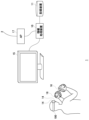
- FIG. 1 shows a configuration example of an information processing system 1 in an embodiment.
- the information processing system 1 includes an information processing device 10, a recording device 11, a head mounted display (HMD) 100, an input device 16 operated by a user's fingers, and an output device 15 for outputting images and sounds.
- Output device 15 may be a television.
- the information processing device 10 is connected to an external network 2 such as the Internet via an access point (AP) 17 .
- the AP 17 has the functions of a wireless access point and router, and the information processing device 10 may be connected to the AP 17 by a cable or by a known wireless communication protocol.
- the recording device 11 records applications such as system software and game software.
- the information processing device 10 may download game software from the content server to the recording device 11 via the network 2 .
- the information processing device 10 executes game software and supplies game image data and audio data to the HMD 100 .
- the information processing device 10 and the HMD 100 may be connected by a known wireless communication protocol, or may be connected by a cable.
- the HMD 100 is a display device that displays an image on a display panel positioned in front of the user's eyes when worn by the user.
- the HMD 100 separately displays a left-eye image on the left-eye display panel and a right-eye image on the right-eye display panel. These images constitute parallax images viewed from left and right viewpoints, and achieve stereoscopic vision. Since the user views the display panel through an optical lens, the information processing apparatus 10 supplies the HMD 100 with parallax image data corrected for optical distortion caused by the lens.
- a user wearing the HMD 100 does not need the output device 15, but by preparing the output device 15, another user can view the display image of the output device 15.
- the information processing apparatus 10 may cause the output device 15 to display the same image as the image viewed by the user wearing the HMD 100, or may cause the output device 15 to display a different image. For example, when a user wearing an HMD and another user play a game together, the output device 15 may display a game image from the viewpoint of the character of the other user.
- the information processing apparatus 10 and the input device 16 may be connected by a known wireless communication protocol, or may be connected by a cable.
- the input device 16 has a plurality of operation members such as operation buttons, and the user operates the operation members with fingers while holding the input device 16 .
- the input device 16 is used as a game controller.
- the input device 16 has an attitude sensor (IMU: Inertial Measurement Unit) including a triaxial acceleration sensor and a triaxial gyro sensor, and transmits sensor data to the information processing apparatus 10 at a predetermined cycle (800 Hz, for example).
- IMU Inertial Measurement Unit
- the game of the embodiment handles not only the operation information of the operation members of the input device 16, but also the position, posture, movement, etc. of the input device 16 as operation information, and reflects the movement of the player character in the virtual three-dimensional space.
- the operation information of the operation member may be used as information for moving the player character
- the operation information such as the position, posture and movement of the input device 16 may be used as information for moving the arm of the player character.
- the movement of the input device 16 is reflected in the movement of the player character with the weapon, thereby realizing intuitive operations for the user and increasing the sense of immersion in the game.
- the input device 16 In order to track the position and orientation of the input device 16, the input device 16 is provided with a plurality of markers (light emitting units) that can be captured by the imaging device 14 mounted on the HMD 100.
- the information processing apparatus 10 analyzes the captured image of the input device 16, estimates position information and orientation information of the input device 16 in real space, and provides the estimated position information and orientation information to the game.
- a plurality of imaging devices 14 are mounted on the HMD 100 .
- the plurality of imaging devices 14 are attached at different positions on the front surface of the HMD 100 in different postures so that the total imaging range, which is the sum of the respective imaging ranges, includes the entire field of view of the user.
- the imaging device 14 comprises an image sensor capable of acquiring images of the markers of the input device 16 .
- the imaging device 14 has a visible light sensor such as a CCD (Charge Coupled Device) sensor or a CMOS (Complementary Metal Oxide Semiconductor) sensor used in general digital video cameras.
- the marker emits non-visible light imaging device 14 has a non-visible light sensor.
- a plurality of imaging devices 14 capture images in front of the user at a predetermined cycle (for example, 120 frames/second) at synchronized timing, and transmit image data of the input device 16 captured to the information processing device 10 .
- the information processing device 10 identifies the positions of the multiple marker images of the input device 16 included in the captured image. Although one input device 16 may be photographed by a plurality of imaging devices 14 at the same timing, the mounting positions and mounting orientations of the imaging devices 14 are known, so the information processing device 10 synthesizes a plurality of captured images. to identify the position of the marker image.
- the three-dimensional shape of the input device 16 and the position coordinates of the plurality of markers arranged on its surface are known, and the information processing apparatus 10 calculates the position coordinates of the input device 16 based on the distribution of the marker images in the captured image. and pose estimation.
- the positional coordinates of the input device 16 may be positional coordinates in a three-dimensional space with the reference position as the origin, and the reference position may be positional coordinates (latitude, longitude) set before the start of the game.
- the information processing apparatus 10 of the embodiment has a function of estimating the position coordinates and orientation of the input device 16 using sensor data detected by the orientation sensor of the input device 16 . Therefore, the information processing apparatus 10 of the embodiment may perform tracking processing of the input device 16 with high accuracy using the estimation result based on the captured image captured by the imaging device 14 and the estimation result based on the sensor data. In this case, the information processing apparatus 10 applies a state estimation technique using a Kalman filter and integrates the estimation result based on the captured image and the estimation result based on the sensor data to obtain the position coordinates of the input device 16 at the current time. and pose may be specified with high accuracy.
- FIG. 2 shows an example of the external shape of the HMD 100.
- the HMD 100 is composed of an output mechanism section 102 and a mounting mechanism section 104 .
- the mounting mechanism unit 104 includes a mounting band 106 that is worn by the user and wraps around the head to fix the HMD 100 to the head.
- the mounting band 106 has a material or structure whose length can be adjusted according to the circumference of the user's head.
- the output mechanism unit 102 includes a housing 108 shaped to cover the left and right eyes when the user wears the HMD 100, and has a display panel inside that faces the eyes when the HMD 100 is worn.
- the display panel may be a liquid crystal panel, an organic EL panel, or the like.
- the housing 108 further includes a pair of left and right optical lenses positioned between the display panel and the user's eyes to expand the viewing angle of the user.
- the HMD 100 may further include speakers and earphones at positions corresponding to the ears of the user, and may be configured to connect external headphones.
- a plurality of imaging devices 14a, 14b, 14c, and 14d are provided on the front outer surface of the housing 108. Based on the front direction of the user's face, the imaging device 14a is attached to the upper right corner of the front outer surface so that the camera optical axis faces diagonally upward to the right, and the imaging device 14b is installed so that the camera optical axis faces diagonally upward to the left.
- the imaging device 14c is attached to the lower right corner of the front outer surface so that the camera optical axis is directed diagonally downward to the right, and the imaging device 14d is installed so that the camera optical axis is diagonally downward to the left. It is mounted in the lower left corner of the front side outer surface facing up.
- the HMD 100 transmits sensor data detected by the orientation sensor and image data captured by the imaging device 14 to the information processing device 10 and receives game image data and game audio data generated by the information processing device 10 .
- FIG. 3 shows the functional blocks of the HMD 100.
- the control unit 120 is a main processor that processes and outputs various data such as image data, audio data, sensor data, and commands.
- Storage unit 122 temporarily stores data, instructions, and the like processed by control unit 120 .
- the orientation sensor 124 acquires sensor data regarding the movement of the HMD 100 .
- the attitude sensor 124 includes at least a triaxial acceleration sensor and a triaxial gyro sensor. The attitude sensor 124 detects the value (sensor data) of each axis component at a predetermined cycle (800 Hz, for example).
- the communication control unit 128 transmits data output from the control unit 120 to the external information processing device 10 by wired or wireless communication via a network adapter or an antenna.
- the communication control unit 128 also receives data from the information processing device 10 and outputs the data to the control unit 120 .
- control unit 120 When the control unit 120 receives game image data and game sound data from the information processing device 10, the control unit 120 supplies the data to the display panel 130 for display, and also supplies the data to the sound output unit 132 for sound output.
- the display panel 130 includes a left-eye display panel 130a and a right-eye display panel 130b, and each display panel displays a pair of parallax images.
- the control unit 120 also causes the communication control unit 128 to transmit sensor data from the attitude sensor 124 , audio data from the microphone 126 , and captured image data from the imaging device 14 to the information processing device 10 .
- FIG. 4(a) shows the shape of the input device 16a for the left hand.
- the input device 16a for the left hand includes a case body 20, a plurality of operation members 22a, 22b, 22c, and 22d operated by a user (hereinafter referred to as "operation members 22" unless otherwise specified), and a case body 20. and a plurality of markers 30 for emitting light to the outside.
- the marker 30 may have an exit surface with a circular cross section.
- the operation member 22 may include an analog stick for tilting operation, a push button, or the like.
- the case body 20 has a grip portion 21 and a curved portion 23 that connects the top portion of the case body and the bottom portion of the case body. The user operates the operation members 22a, 22b, 22c, and 22d with the thumb of the left hand while gripping the grip portion 21. As shown in FIG.
- FIG. 4(b) shows the shape of the input device 16b for the right hand.
- the input device 16b for the right hand includes a case body 20, a plurality of operation members 22e, 22f, 22g, and 22h operated by the user (hereinafter referred to as "operation members 22" unless otherwise specified), and the case body 20. and a plurality of markers 30 for emitting light to the outside.
- the operation member 22 may include an analog stick for tilting operation, a push button, or the like.
- the case body 20 has a grip portion 21 and a curved portion 23 that connects the top portion of the case body and the bottom portion of the case body. The user operates the operation members 22e, 22f, 22g, and 22h with the thumb of the right hand while gripping the grip portion 21. As shown in FIG.
- FIG. 5 shows the shape of the input device 16b for the right hand.
- the input device 16b has operation members 22i and 22j in addition to the operation members 22e, 22f, 22g and 22h shown in FIG. 4(b). While gripping the grip portion 21, the user operates the operation member 22i with the index finger of the right hand and operates the operation member 22j with the middle finger.
- the input device 16a and the input device 16b will be referred to as the "input device 16" unless otherwise distinguished.
- the operation member 22 provided on the input device 16 is equipped with a touch sensing function that recognizes a finger just by touching it without pressing it.
- the operating members 22f, 22g, 22j may comprise capacitive touch sensors.
- the touch sensor may be mounted on another operation member 22, but is preferably mounted on an operation member that does not come into contact with the mounting surface when the input device 16 is placed on a table or the like.
- the marker 30 is a light emitting portion that emits light to the outside of the case body 20.
- the surface of the case body 20 includes a resin portion that diffuses and emits light from a light source such as an LED (Light Emitting Diode) element to the outside. .
- the marker 30 is captured by the imaging device 14 and used for estimating the position and orientation of the input device 16 . Since the image pickup device 14 photographs the space at a predetermined cycle (for example, 120 frames/second), the marker 30 emits light in synchronization with the periodic image pickup timing of the image pickup device 14, and the non-exposure period by the image pickup device 14. It is preferable to suppress unnecessary power consumption by turning off the light.
- the image captured by the imaging device 14 is used for tracking processing of the input device 16 and tracking processing (SLAM) of the HMD 100. Therefore, an image captured at 60 frames/second is used for the tracking process of the input device 16, and another image captured at 60 frames/second is used for the process of simultaneously performing self-position estimation and environment map creation of the HMD 100. may be used.
- FIG. 6 shows an example of part of an image of the input device 16 captured.
- This image is a photographed image of the input device 16b held in the right hand, and includes images of a plurality of markers 30 emitting light.
- the communication control unit 128 transmits image data captured by the imaging device 14 to the information processing device 10 at predetermined intervals.
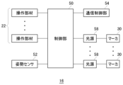
- FIG. 7 shows functional blocks of the input device 16.
- the control unit 50 receives operation information input to the operation member 22 and also receives sensor data acquired by the attitude sensor 52 .
- the attitude sensor 52 acquires sensor data regarding the movement of the input device 16 and includes at least a three-axis acceleration sensor and a three-axis gyro sensor.
- the attitude sensor 52 detects the value (sensor data) of each axial component at a predetermined cycle (800 Hz, for example).
- the control unit 50 supplies the received operation information and sensor data to the communication control unit 54 .
- the communication control unit 54 transmits operation information and sensor data output from the control unit 50 to the information processing device 10 by wired or wireless communication via a network adapter or an antenna.
- the communication control unit 54 also acquires a light emission instruction from the information processing device 10 .
- the input device 16 includes multiple light sources 58 for lighting multiple markers 30 .
- Light source 58 may be an LED element that emits light in a predetermined color.
- the control unit 50 causes the light source 58 to emit light based on the light emission instruction acquired from the information processing device 10 and lights the marker 30 .
- one light source 58 is provided for one marker 30 in the example shown in FIG. 7 , one light source 58 may light a plurality of markers 30 .
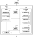
- FIG. 8 shows functional blocks of the information processing device 10 .
- the information processing device 10 includes a processing unit 200 and a communication unit 202 , and the processing unit 200 includes an acquisition unit 210 , a game execution unit 220 , an image signal processing unit 222 , an estimation processing unit 230 and a marker information holding unit 250 .
- the communication unit 202 receives operation information of the operation member 22 and sensor data transmitted from the input device 16 and supplies the information to the acquisition unit 210 .
- the communication unit 202 also receives captured image data and sensor data transmitted from the HMD 100 and supplies the data to the acquisition unit 210 .
- the acquisition unit 210 includes a captured image acquisition unit 212 , a sensor data acquisition unit 214 and an operation information acquisition unit 216 .
- the estimation processing unit 230 includes a marker image coordinate specifying unit 232, a marker image coordinate extracting unit 240, and a position/orientation deriving unit 242.
- the marker image coordinate specifying unit 232 includes a first extraction processing unit 234, a second extraction processing unit 236, and a It has a representative coordinate derivation unit 238 .
- the estimation processing unit 230 estimates position information and orientation information of the input device 16 based on the marker image included in the captured image.
- the estimation processing unit 230 estimates the position information and orientation information of the input device 16 estimated from the marker image included in the captured image, and the sensor data detected by the input device 16. By inputting the position information and orientation information of the input device 16 to the Kalman filter, the position information and orientation information of the input device 16 may be estimated with high accuracy.
- the estimation processing unit 230 supplies the estimated position information and orientation information of the input device 16 to the game execution unit 220 .
- the information processing device 10 includes a computer, and various functions shown in FIG. 8 are realized by the computer executing programs.
- a computer includes, as hardware, a memory for loading a program, one or more processors for executing the loaded program, an auxiliary storage device, and other LSIs.
- a processor is composed of a plurality of electronic circuits including semiconductor integrated circuits and LSIs, and the plurality of electronic circuits may be mounted on one chip or may be mounted on a plurality of chips.
- the functional blocks shown in FIG. 8 are realized by cooperation of hardware and software, and therefore those skilled in the art will understand that these functional blocks can be realized in various forms by hardware alone, software alone, or a combination thereof. It is understood.
- the photographed image acquisition unit 212 acquires image data obtained by photographing the input device 16 having a plurality of markers 30 and supplies the image data to the image signal processing unit 222 .
- the image signal processing unit 222 performs image signal processing such as noise reduction and optical correction (shading correction) on the image data, and supplies captured image data with high image quality to the estimation processing unit 230 .
- the captured image acquisition unit 212 supplies the horizontal line data of the image to the image signal processing unit 222 line by line.
- the image signal processing unit 222 of the embodiment is configured by hardware, stores several lines of image data in a line buffer, and performs image quality enhancement processing on the several lines of image data stored in the line buffer. , supplies the high-quality line data to the estimation processing unit 230 .
- the sensor data acquisition unit 214 acquires sensor data transmitted from the input device 16 and the HMD 100 and supplies it to the estimation processing unit 230 .
- the operation information acquisition unit 216 acquires operation information transmitted from the input device 16 and supplies it to the game execution unit 220 .
- the game execution unit 220 progresses the game based on the operation information and the position/orientation information of the input device 16 .
- the marker image coordinate specifying unit 232 specifies two-dimensional coordinates (hereinafter also referred to as "marker image coordinates") that represent the image of the marker 30 included in the captured image.
- the marker image coordinate specifying unit 232 may specify a region in which pixels having luminance values equal to or greater than a predetermined value are continuous, calculate the coordinates of the center of gravity of the pixel region, and use them as the representative coordinates of the marker image. A method of deriving representative coordinates by the marker image coordinate specifying unit 232 will be described later.
- a method of solving a PNP (Perspective n-Point) problem is known as a method of estimating the position and orientation of an imaging device that has taken an image of an object whose three-dimensional shape and size are known.
- the marker image coordinate extraction unit 240 extracts N (N is an integer equal to or greater than 3) two-dimensional marker image coordinates in the captured image
- the position/orientation derivation unit 242 extracts the coordinates extracted by the marker image coordinate extraction unit 240.
- the position information and orientation information of the input device 16 are derived from the N marker image coordinates and the three-dimensional coordinates of the N markers in the three-dimensional model of the input device 16 .
- the position and orientation derivation unit 242 estimates the position and orientation of the imaging device 14 using the following (Equation 1), and derives position information and orientation information of the input device 16 in the three-dimensional space based on the estimation results. .
- (u, v) are the marker image coordinates in the captured image
- (X, Y, Z) are the three-dimensional space of the marker 30 when the three-dimensional model of the input device 16 is in the reference position and orientation.
- the marker information holding unit 250 holds the 3D coordinates of each marker in the 3D model in the reference position and the reference orientation, and the position/posture derivation unit 242 obtains the 3D coordinates of each marker from the marker information holding unit 250. Read to get (X, Y, Z).
- (f x , f y ) is the focal length of the imaging device 14 and (c x , c y ) is the image principal point, both of which are internal parameters of the imaging device 14 .
- a matrix whose elements are r 11 to r 33 and t 1 to t 3 is a rotation/translation matrix.
- (u, v), (f x , f y ), (c x , c y ), and (X, Y, Z) are known in (Equation 1), and the position/orientation derivation unit 242 calculates N markers Solving the equations for 30 gives their common rotation-translation matrix.
- the position and orientation derivation unit 242 derives the position information and orientation information of the input device 16 based on the angle and translation amount represented by this matrix.
- the process of estimating the position and orientation of the input device 16 is performed by solving the P3P problem, so the position and orientation derivation unit 242 obtains three marker image coordinates and three are used to derive the position and orientation of the input device 16 .
- the information processing apparatus 10 generates the world coordinates of the three-dimensional real space by SLAM technology, and therefore the position/orientation derivation unit 242 derives the position and orientation of the input device 16 in the world coordinate system.
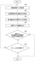
- FIG. 9 is a flowchart showing position and orientation estimation processing by the estimation processing unit 230.
- the photographed image obtaining unit 212 sequentially obtains line data of images obtained by photographing the input device 16 ( S ⁇ b>10 ), and supplies the line data to the image signal processing unit 222 .
- the captured image acquisition unit 212 performs binning processing (processing for combining four pixels into one pixel) on the acquired two line data, and supplies the data to the image signal processing unit 222 .
- the image signal processing unit 222 stores several lines of line data in a line buffer and performs image signal processing such as noise reduction and optical correction (S12).
- the image signal processing unit 222 supplies the line data subjected to the image signal processing to the marker image coordinate specifying unit 232, and the marker image coordinate specifying unit 232 specifies the representative coordinates of the multiple marker images included in the captured image (S14). .
- the line data subjected to image signal processing and the representative coordinates of the specified marker image are temporarily stored in a memory (not shown).
- the marker image coordinate extraction unit 240 extracts arbitrary three marker image coordinates from among the plurality of marker image coordinates specified by the marker image coordinate specifying unit 232.
- the marker information holding unit 250 holds the three-dimensional coordinates of each marker in the three-dimensional model of the input device 16 in the reference position and the reference orientation.
- the position/orientation derivation unit 242 reads the 3D coordinates of the markers in the 3D model from the marker information storage unit 250 and solves the P3P problem using (Equation 1). After identifying the rotation/translation matrix common to the three extracted marker image coordinates, the position/orientation derivation unit 242 uses the marker image coordinates of the input device 16 other than the extracted three marker image coordinates to calculate the reprojection error. Calculate
- the marker image coordinate extraction unit 240 extracts a predetermined number of combinations of three marker image coordinates.
- the position/orientation deriving unit 242 identifies a rotation/translation matrix for each combination of the extracted three marker image coordinates, and calculates each reprojection error. Then, the position/orientation derivation unit 242 identifies the rotation/translation matrix with the smallest reprojection error from among the predetermined number of reprojection errors, and derives the position information and orientation information of the input device 16 (S16).
- the position/orientation derivation unit 242 supplies the derived position information and orientation information of the input device 16 to the game execution unit 220 .
- the position/orientation estimation process is performed at the tracking image capturing cycle (60 frames/second) of the input device 16 (N in S18).
- the position/orientation estimation processing by the estimation processing unit 230 ends (Y in S18).
- the photographed image of the embodiment is a gray scale image, and the brightness of each pixel is represented by 8 bits and has a brightness value of 0-255.
- the marker image is captured as a high-luminance image as shown in FIG.
- FIG. 10 is a flow chart showing the process by which the first extraction processing unit 234 extracts connected components of eight neighboring pixels from the captured image.
- the first extraction processing unit 234 acquires line data that has undergone image signal processing from the image signal processing unit 222 (S20).
- the first extraction processing unit 234 performs a process of extracting connected components of eight neighboring pixels from the captured image (S22).
- FIG. 11 shows an example of a captured frame image.
- the bright object included in the lower part of the image is the illuminated marker 30 .
- the image signal processing unit 222 supplies the horizontal line data of the frame image to the first extraction processing unit 234 in order from the top in the vertical direction.
- the line data supplied from the image signal processing section 222 may be sequentially stored in a memory (not shown).
- FIG. 12 is a diagram for explaining the order of reading line data of an image.
- the first extraction processing unit 234 receives the horizontal line data of the frame image in order from the top, and performs processing for extracting connected components of eight neighboring pixels.
- FIG. 13(a) is a diagram for explaining 8 neighboring pixels.
- CCL Connected-component labeling
- pixels present around one pixel P up, down, left, right, and four diagonal directions
- the two pixels are said to be 8-neighboring, and a set of pixels connected by 8-neighboring is defined as In this embodiment, it is called "first connected component”.
- the first extraction processing unit 234 is configured by hardware, and when two or three line data are input from the image signal processing unit 222, it performs processing for extracting connected components of eight neighboring pixels.
- the second extraction processing unit 236 of the embodiment performs processing for extracting connected components of four neighboring pixels by software calculation.
- FIG. 13B is a diagram for explaining four neighboring pixels. With one pixel P as the center, the pixels present in the vertical and horizontal directions are referred to as "four neighboring pixels". 4 Neighboring pixels do not include pixels existing in the diagonal direction. In a binary image, when two pixels with the same value exist within 4-neighborhood of each other, the two pixels are said to be 4-adjacent, and a set of pixels connected by 4-neighborhood is defined as In this embodiment, it is called a "second connected component".
- the processing function of the second extraction processing unit 236 is realized by software calculation by DSP. A process of extracting components is performed.
- the connected component of 8 neighboring pixels includes pixels connected in an oblique direction.
- the size of the 8-neighboring connected component is greater than or equal to the size of the 4-neighboring connected component
- the number of extracted 8-neighboring connected components is equal to or less than the number of 4-neighboring connected components extracted.
- the first extraction processing unit 234 searches for an area in which pixels having a first brightness or more are connected in the vicinity of eight pixels in the captured image.
- the first luminance may be a luminance value of 128.
- FIG. 14 shows an example of multiple pixels in a captured image.
- pixels with the highest luminance value of 255 are expressed in white, and pixels with the lowest luminance value of 0 are expressed in black.
- priority is given to visibility, and the luminance representation of each pixel is reversed (black and white are reversed). Therefore, in FIGS. 14 to 16 and 20 to 22, black expresses a luminance value of 255 (the highest luminance value) and white expresses a luminance value of 0 (the lowest luminance value).
- the first extraction processing unit 234 finds an area in which pixels of the first luminance or higher are connected in 8 neighborhoods, it extracts it as the first connected component of the 8 neighborhood pixels (S22), and draws a bounding box surrounding the first connected component. Specify (S24).
- FIG. 15 shows a bounding box 80a surrounding the first connected component 78a of the extracted 8 neighboring pixels.
- a bounding box 80a is identified as the smallest rectangle that encloses the first connected component 78a of eight neighboring pixels.
- the first extraction processing unit 234 performs the extraction processing of the first connected component for each line data of the image, when the first connected component 78a is extracted, another first connected component shown below is extracted. not aware of its existence. After identifying the bounding box 80a, the first extraction processing unit 234 outputs the coordinate information (bounding box information) of the bounding box 80a to a memory (not shown) for storage (S26).
- the first extraction processing unit 234 determines whether the number of extracted first connected components is within a predetermined upper limit (S28).
- the upper limit may be set to 256.
- the position/orientation estimation process is performed at the tracking image capturing cycle (60 frames/second) of the input device 16. Therefore, when the number of extracted first connected components becomes enormous, the position/orientation estimation process is performed. It becomes difficult to complete within the period. Therefore, an upper limit is set for the number of first connected components extracted by the first extraction processing unit 234, and when the number of extracted first connected components exceeds the upper limit (N in S28), the first extraction processing unit 234 ) to forcibly terminate the extraction process of the first connected component.
- steps S20 to S26 are repeatedly performed until processing of one frame of the captured image is completed (N of S30).
- FIG. 16 shows a bounding box 80b surrounding another first connected component 78b extracted at S22.
- a bounding box 80b is identified as the smallest rectangle that encloses the first connected component 78b of eight neighboring pixels.
- the first extraction processing section 234 outputs the coordinate information of the bounding box 80b to the memory. When the processing of one frame of the captured image ends (Y of S30), the first extraction processing section 234 starts processing the next frame image.
- FIG. 17 shows an example of bounding boxes extracted from a captured image.
- the first extraction processing unit 234 extracts a plurality of first connected components of 8 neighboring pixels from the photographed image, and outputs information of bounding boxes surrounding each of the plurality of first connected components to a memory for storage.
- the bounding box of the marker image is specified on the lower side of the captured image
- the bounding box of the light source image such as illumination light is specified on the upper side of the captured image.
- the user operates the input device 16 at a position close to the HMD 100, so a bounding box surrounding a large marker image is identified below the captured image.
- the first extraction processing unit 234 may erroneously extract a plurality of marker images as one first connected component.
- FIG. 18 shows an example of erroneously extracting two marker images as one first connected component.
- the first extraction processing unit 234 extracts the two marker images as one first connected component, and extracts the two marker images.
- a bounding box surrounding the image is specified. Therefore, the second extraction processing unit 236 of the embodiment has a function of separating a plurality of marker images included in the bounding box specified by the first extraction processing unit 234 .
- FIG. 19 is a flowchart showing the process of extracting the second connected components of a plurality of four neighboring pixels from the first connected components included in the bounding box by the second extraction processing unit 236 .
- the second extraction processing unit 236 investigates whether the first connected component extracted by the first extraction processing unit 234 can be separated into a plurality of second connected components of four neighboring pixels.
- the first connected component is discarded and replaced with a plurality of separated second connected components, and if it cannot be separated, the original first connected component is maintained.
- the second extraction processing unit 236 acquires the bounding box information (coordinate information) specified by the first extraction processing unit 234 from the memory (S40). At this time, the second extraction processing unit 236 also acquires the captured image data including the bounding box and its periphery from the memory storing the captured image data (S42).
- FIG. 20 shows an example of a captured image including the area of the bounding box 80a.
- the width and height of the captured image area to be acquired are approximately twice the width and height of the bounding box 80a, and are set such that the center position of the image area substantially coincides with the center position of the bounding box 80a.
- the second extraction processing unit 236 checks the contrast between the bounding box 80a identified by the first extraction processing unit 234 and its surroundings (S44). If the bounding box 80a contains the mark image, the average brightness within the bounding box 80a is high, while the average brightness outside the bounding box 80a is relatively low. Therefore, the second extraction processing unit 236 calculates the average brightness in the bounding box 80a and the average brightness in the area outside the bounding box 80a among the acquired image areas, and obtains the brightness ratio.
- the second extraction processing unit 236 calculates the average brightness B1 of pixels within the bounding box 80a and the average brightness B2 of pixels within the image area outside the bounding box 80a. If the luminance ratio (B1/B2) is less than the predetermined value (N in S44), the second extraction processing unit 236 determines that the first connected component included in the bounding box 80a is not to be separated, and Stop the separation process of the first connected component.
- the predetermined value may be 3, for example. At this time, the second extraction processing unit 236 may determine that the bounding box 80a does not contain the marker image and discard the bounding box 80a.
- the second extraction processing section 236 checks whether the size and shape of the bounding box 80a satisfy predetermined conditions (S46). Specifically, the second extraction processing unit 236 determines whether the number of pixels x in the horizontal direction and the number of pixels y in the vertical direction satisfy the following conditions 1 to 4. (Condition 1) Xmin ⁇ x ⁇ Xmax (Condition 2) Ymin ⁇ y ⁇ Ymax (Condition 3) x/y ⁇ Aspect_Thresh (Condition 4) y/x ⁇ Aspect_Thresh
- Conditions 1 and 2 specify that the size of the bounding box 80a is within a predetermined range, that is, the bounding box 80a is neither too large nor too small.
- each marker image is always small (if each marker image is large, it is unlikely that a plurality of marker images are extracted as one first connected component). no), and the number of pixels x and the number of pixels y are less than Xmax and Ymax, respectively. If the bounding box 80a is too small, it is unlikely that it contains the marker image. Therefore, the bounding box 80a with the number of pixels x and the number of pixels y equal to or larger than Xmin and Ymin, respectively, is targeted for investigation.
- Conditions 3 and 4 are conditions for excluding the elongated bounding box 80a from the investigation target.
- the second extraction processing unit 236 determines that the size and shape of the bounding box 80a do not satisfy any of the conditions 1 to 4 (N of S46), the first connected component included in the bounding box 80a is separated. It is determined that it is not a target, and the separation processing of the first connected component is stopped.
- the second extraction processing unit 236 determines that the size and shape of the bounding box 80a satisfy all conditions 1 to 4 (Y in S46), it separates the first connected component included in the bounding box 80a. process for Specifically, the second extraction processing unit 236 searches the first connected component for a four-neighboring connected region, and extracts the second connected component of the four-neighboring pixels.
- FIG. 21 shows a target area for extracting the second connected components of four neighboring pixels.
- This target area is an area obtained by extending the bounding box 80a by one pixel to both sides in the horizontal direction and both sides in the vertical direction.
- the second extraction processing unit 236 searches for an area in which pixels having the second luminance or more are connected in four neighborhoods.
- the second luminance may be the same as the first luminance, but may be higher than the first luminance, for example the second luminance may have a luminance value of 160.
- the second extraction processing unit 236 finds a region in which pixels of the second brightness or more are connected in four neighborhoods, it extracts the second connected component of the four neighborhood pixels (S48), and draws a bounding box surrounding the second connected component. Identify (S50). If the second extraction processing unit 236 does not extract a plurality of second connected components from the first connected component (N in S52), the second extraction processing unit 236 determines that the first connected component included in the bounding box 80a is not to be separated, The separation processing of the first connected component is stopped.
- the second extraction processing unit 236 extracts a plurality of second connected components from the first connected component (Y in S52), the second extraction processing unit 236 replaces the first connected component 78a included in the bounding box 80a with a plurality of second connected components. Separate into connected components (S54).
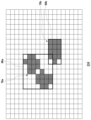
- FIG. 22 shows a bounding box surrounding the second connected component of the extracted four neighboring pixels.
- the second extraction processing unit 236 extracts three second connected components 82a, 82b, 82c from the target region shown in FIG. Identify.
- the second extraction processing unit 236 assigns the label value 1 to the second connected component 82a, the label value 2 to the second connected component 82b, and the label value 3 to the second connected component 82c according to the CCL algorithm. are doing. Since the second connected component 82c labeled with the label value 3 includes pixels outside the bounding box 80a, the second extraction processing unit 236 determines that the second connected component 82c is recognizing that it is not separate from
- the first connected component 78a connected in the vicinity of 8 is separated into the second connected component 82a and the second connected component 82b in the vicinity of 4.
- the second extraction processing unit 236 converts the first connected component 78a extracted by the first extraction processing unit 234 into the second connected component 82a and the second connected component 82b. Replace with the second connected component 82b. Specifically, the second extraction processing unit 236 discards the first connected component 78a and extracts the second The connecting component 82a and the second connecting component 82b may be substituted. This processing makes it possible to separate the two marker images that have been erroneously extracted as one first connected component 78a. When the first connected component 78a is separated into a predetermined number (for example, 3 or 4) or more, the second extraction processing unit 236 determines that the separation process is not appropriate, and extracts the first connected component 78a. may be maintained.
- the second extraction processing unit 236 investigates whether or not separable first connected components are included in all bounding boxes identified by the first extraction processing unit 234 (N of S56).
- the representative coordinate deriving unit 238 extracts the pixels of the first connected component and/or the second Based on the pixels of the second connected component extracted by the extraction processing unit 236, a process of deriving the representative coordinates of the marker image is performed.
- FIG. 23 shows a flowchart showing the process of deriving the representative coordinates.
- the representative coordinate derivation unit 238 uses the bounding box specified by the first extraction processing unit 234 and the bounding box specified by the second extraction processing unit 236 to derive the representative coordinates of the marker image.
- the representative coordinate derivation unit 238 checks whether the bounding box identified by the first extraction processing unit 234 and the second extraction processing unit 236 includes the marker image against several criteria. First, the representative coordinate derivation unit 238 acquires bounding box information (S60), and checks whether the size of the bounding box is within a predetermined range (S62). If the bounding box is too large (N of S62), the first connected component or the second connected component included in the bounding box is not the captured image of the marker 30 . Therefore, the representative coordinate derivation unit 238 discards the bounding box that is too large.
- S60 bounding box information
- S62 predetermined range
- the second extraction processing unit 236 checks whether the shape of the connected components of the high-brightness pixels included in the bounding box is elongated ( S64). Since the marker 30 has an output surface with a circular cross section, the marker image has a shape close to a circle and does not have an elongated shape. If the shape of the connected component of the high-brightness pixels is a long shape (Y of S64), the high-brightness lighting body included in the bounding box is not the marker 30. Therefore, the representative coordinate derivation unit 238 discard the box.
- the representative coordinate derivation unit 238 confirms the contrast between the specified bounding box and its surroundings (S66). This contrast confirmation process may be the same process as the process shown in S44 of FIG. 19, for example. If the ratio of the average brightness within the bounding box and the average brightness within the predetermined area outside the bounding box is less than the predetermined value (N of S66), the representative coordinate derivation unit 238 discards the bounding box.
- the representative coordinate derivation unit 238 recognizes that the bounding box contains a marker image, Based on this, the representative coordinates of the marker image are derived (S68).
- the representative coordinates may be barycentric coordinates.
- the third luminance may be lower than the first luminance, for example a luminance value of 64.
- the representative coordinate derivation unit 238 calculates the brightness average position in the X-axis direction and the Y-axis direction, and derives the representative coordinates (u, v). At this time, it is preferable that the representative coordinate derivation unit 238 derives the representative coordinates (u, v) by adding the pixel value of each pixel having the third luminance or higher to determine the luminance centroid position.
- the upper limit is set for the number of first connected components that can be extracted by the first extraction processing unit 234.
- the first extraction processing unit 234 forcibly terminates the extraction processing of the first connected components.
- the separation process described above may be performed on the first connected component of .
- FIG. 24 shows an example of the bounding box extracted by the first extraction processing unit 234 in the captured image.
- This photographed image includes a blind that is attached to the inside of the window for purposes such as sunshade and blindness.
- the blinds photographed here are Venetian blinds with multiple horizontal slats arranged vertically, and are a type of blinds often used in offices.
- the first extraction processing unit 234 of the embodiment is configured by hardware that sequentially acquires line data of an image and extracts the first connected components of eight neighboring pixels.
- the arrows shown in FIG. 24 indicate the order in which the line data of the image are read from the image sensor of the imaging device 14, and the first extraction processing unit 234 extracts the first connected component based on the read line data. Take action.
- the first extraction processing unit 234 sequentially performing the extraction processing of the first connected components from the top to the bottom of the captured image, before finishing the processing of all the image data, The number of extracted first connected components has reached the upper limit (256), and the process of extracting the first connected components has been forcibly terminated.
- the marker image obtained by photographing the marker 30 of the input device 16 exists in the lower left of the image. is not extracted.
- the input device 16 is photographed by the image sensor of the imaging device 14 mounted on the HMD 100. Therefore, when the user is playing the game normally, the input device 16 has an angle of view Photographed on the bottom side of the inside. Therefore, in the HMD 100 , the control unit 120 may read the image data from the image sensor of the imaging device 14 by flipping it upside down, and transmit the read image data from the communication control unit 128 to the information processing device 10 .
- the photographed image acquisition unit 212 acquires the image data read out from the image sensor after being vertically inverted. Therefore, the captured image acquisition unit 212 sequentially acquires the line data of the captured image from the bottom of the image, and supplies the line data to the estimation processing unit 230 via the image signal processing unit 222 .
- the first extraction processing unit 234 can extract the first connected component in which pixels having a predetermined brightness or more are continuous from the image data read out from the image sensor after being vertically inverted, and the number of the extracted first connected components is It is possible to increase the possibility of extracting the first connected component corresponding to the marker image existing on the lower side of the captured image before reaching the upper limit number.
- the present disclosure has been described above based on the examples. It should be understood by those skilled in the art that the above embodiments are examples, and that various modifications can be made to combinations of each component and each treatment process, and such modifications are also within the scope of the present disclosure. .
- the information processing apparatus 10 performs the estimation process in the embodiment, the functions of the information processing apparatus 10 may be provided in the HMD 100 and the HMD 100 may perform the estimation process. That is, the HMD 100 may be the information processing device 10 .
- the imaging device 14 is attached to the HMD 100 in the embodiment, the imaging device 14 may be attached to a position other than the HMD 100 as long as it can capture the marker image.
- the present disclosure can be used in the technical field of detecting marker images included in captured images.
Landscapes
- Engineering & Computer Science (AREA)
- Computer Vision & Pattern Recognition (AREA)
- Physics & Mathematics (AREA)
- General Physics & Mathematics (AREA)
- Theoretical Computer Science (AREA)
- Image Analysis (AREA)
- Length Measuring Devices By Optical Means (AREA)
Priority Applications (1)
| Application Number | Priority Date | Filing Date | Title |
|---|---|---|---|
| US18/727,673 US20250095193A1 (en) | 2022-02-14 | 2022-12-22 | Information processing apparatus and representative coordinate derivation method |
Applications Claiming Priority (2)
| Application Number | Priority Date | Filing Date | Title |
|---|---|---|---|
| JP2022-020559 | 2022-02-14 | ||
| JP2022020559A JP7777002B2 (ja) | 2022-02-14 | 2022-02-14 | 情報処理装置および代表座標導出方法 |
Publications (1)
| Publication Number | Publication Date |
|---|---|
| WO2023153094A1 true WO2023153094A1 (ja) | 2023-08-17 |
Family
ID=87564251
Family Applications (1)
| Application Number | Title | Priority Date | Filing Date |
|---|---|---|---|
| PCT/JP2022/047378 Ceased WO2023153094A1 (ja) | 2022-02-14 | 2022-12-22 | 情報処理装置および代表座標導出方法 |
Country Status (3)
| Country | Link |
|---|---|
| US (1) | US20250095193A1 (https=) |
| JP (1) | JP7777002B2 (https=) |
| WO (1) | WO2023153094A1 (https=) |
Cited By (1)
| Publication number | Priority date | Publication date | Assignee | Title |
|---|---|---|---|---|
| WO2025148572A1 (zh) * | 2024-01-09 | 2025-07-17 | 腾讯科技(深圳)有限公司 | 目标检测方法、装置、电子设备及存储介质 |
Citations (4)
| Publication number | Priority date | Publication date | Assignee | Title |
|---|---|---|---|---|
| JP2003030628A (ja) * | 2001-07-18 | 2003-01-31 | Fujitsu Ltd | 相対位置計測装置 |
| JP2004213589A (ja) * | 2003-01-09 | 2004-07-29 | Mitsubishi Electric Corp | 特定部分姿勢推定装置 |
| WO2015019573A1 (ja) * | 2013-08-08 | 2015-02-12 | パナソニック インテレクチュアル プロパティ コーポレーション オブ アメリカ | 情報処理装置の制御方法および画像処理方法 |
| JP2020181322A (ja) * | 2019-04-24 | 2020-11-05 | 株式会社ソニー・インタラクティブエンタテインメント | 情報処理装置および代表座標導出方法 |
Family Cites Families (4)
| Publication number | Priority date | Publication date | Assignee | Title |
|---|---|---|---|---|
| JP5365440B2 (ja) * | 2009-09-15 | 2013-12-11 | 富士ゼロックス株式会社 | 画像処理装置及び画像処理プログラム |
| JP5600524B2 (ja) * | 2010-08-27 | 2014-10-01 | キヤノン株式会社 | 画像処理装置、画像処理方法、プログラム、および記憶媒体 |
| US9262583B2 (en) * | 2013-03-29 | 2016-02-16 | Case Western Reserve University | Image similarity-based finite element model registration |
| CA3230414A1 (en) * | 2021-09-20 | 2023-03-23 | Hetalkumar Meghrajbhai DESAI | Methods and apparatuses for detecting anomalies when filling a container with fluid |
-
2022
- 2022-02-14 JP JP2022020559A patent/JP7777002B2/ja active Active
- 2022-12-22 US US18/727,673 patent/US20250095193A1/en active Pending
- 2022-12-22 WO PCT/JP2022/047378 patent/WO2023153094A1/ja not_active Ceased
Patent Citations (4)
| Publication number | Priority date | Publication date | Assignee | Title |
|---|---|---|---|---|
| JP2003030628A (ja) * | 2001-07-18 | 2003-01-31 | Fujitsu Ltd | 相対位置計測装置 |
| JP2004213589A (ja) * | 2003-01-09 | 2004-07-29 | Mitsubishi Electric Corp | 特定部分姿勢推定装置 |
| WO2015019573A1 (ja) * | 2013-08-08 | 2015-02-12 | パナソニック インテレクチュアル プロパティ コーポレーション オブ アメリカ | 情報処理装置の制御方法および画像処理方法 |
| JP2020181322A (ja) * | 2019-04-24 | 2020-11-05 | 株式会社ソニー・インタラクティブエンタテインメント | 情報処理装置および代表座標導出方法 |
Cited By (1)
| Publication number | Priority date | Publication date | Assignee | Title |
|---|---|---|---|---|
| WO2025148572A1 (zh) * | 2024-01-09 | 2025-07-17 | 腾讯科技(深圳)有限公司 | 目标检测方法、装置、电子设备及存储介质 |
Also Published As
| Publication number | Publication date |
|---|---|
| JP7777002B2 (ja) | 2025-11-27 |
| JP2023117801A (ja) | 2023-08-24 |
| US20250095193A1 (en) | 2025-03-20 |
Similar Documents
| Publication | Publication Date | Title |
|---|---|---|
| JP7248490B2 (ja) | 情報処理装置、デバイスの位置および姿勢の推定方法 | |
| CN109146965B (zh) | 信息处理装置、计算机可读介质和头戴式显示装置 | |
| CN110047104A (zh) | 对象检测和跟踪方法、头戴式显示装置和存储介质 | |
| JP7367689B2 (ja) | 情報処理装置、情報処理方法、及び記録媒体 | |
| JP6768933B2 (ja) | 情報処理装置、情報処理システム、および画像処理方法 | |
| JP7198149B2 (ja) | 情報処理装置およびデバイス情報導出方法 | |
| JP7353773B2 (ja) | 複数のマーカを備えたデバイス | |
| WO2023153094A1 (ja) | 情報処理装置および代表座標導出方法 | |
| JP6499993B2 (ja) | 情報処理装置、情報処理システム、および情報処理方法 | |
| JP7288792B2 (ja) | 情報処理装置およびデバイス情報導出方法 | |
| US12260490B2 (en) | Three-dimensional image processing apparatus, system, and method thereof | |
| JP7812241B2 (ja) | 情報処理装置および代表座標導出方法 | |
| JP2024106855A (ja) | 情報処理装置およびデバイス位置取得方法 | |
| JP7719010B2 (ja) | 情報処理装置およびデバイス位置推定方法 | |
| JP2023019059A (ja) | 撮像装置及び撮像システム | |
| JP7710386B2 (ja) | 情報処理装置、デバイス速度推定方法およびデバイス位置推定方法 | |
| US20240257391A1 (en) | Information processing apparatus and device information derivation method | |
| JP6930011B2 (ja) | 情報処理装置、情報処理システム、および画像処理方法 | |
| JP7634069B2 (ja) | 複数のマーカを備えたデバイス | |
| WO2023157338A1 (ja) | 情報処理装置およびデバイス位置推定方法 |
Legal Events
| Date | Code | Title | Description |
|---|---|---|---|
| 121 | Ep: the epo has been informed by wipo that ep was designated in this application |
Ref document number: 22926108 Country of ref document: EP Kind code of ref document: A1 |
|
| WWE | Wipo information: entry into national phase |
Ref document number: 18727673 Country of ref document: US |
|
| NENP | Non-entry into the national phase |
Ref country code: DE |
|
| 122 | Ep: pct application non-entry in european phase |
Ref document number: 22926108 Country of ref document: EP Kind code of ref document: A1 |
|
| WWP | Wipo information: published in national office |
Ref document number: 18727673 Country of ref document: US |