WO2023149437A1 - 管理システム - Google Patents
管理システム Download PDFInfo
- Publication number
- WO2023149437A1 WO2023149437A1 PCT/JP2023/003102 JP2023003102W WO2023149437A1 WO 2023149437 A1 WO2023149437 A1 WO 2023149437A1 JP 2023003102 W JP2023003102 W JP 2023003102W WO 2023149437 A1 WO2023149437 A1 WO 2023149437A1
- Authority
- WO
- WIPO (PCT)
- Prior art keywords
- chip
- gaming
- game
- chips
- payout
- Prior art date
- Legal status (The legal status is an assumption and is not a legal conclusion. Google has not performed a legal analysis and makes no representation as to the accuracy of the status listed.)
- Ceased
Links
Images


























Classifications
-
- G—PHYSICS
- G07—CHECKING-DEVICES
- G07F—COIN-FREED OR LIKE APPARATUS
- G07F17/00—Coin-freed apparatus for hiring articles; Coin-freed facilities or services
- G07F17/32—Coin-freed apparatus for hiring articles; Coin-freed facilities or services for games, toys, sports, or amusements
- G07F17/3244—Payment aspects of a gaming system, e.g. payment schemes, setting payout ratio, bonus or consolation prizes
- G07F17/3248—Payment aspects of a gaming system, e.g. payment schemes, setting payout ratio, bonus or consolation prizes involving non-monetary media of fixed value, e.g. casino chips of fixed value
-
- G—PHYSICS
- G06—COMPUTING OR CALCULATING; COUNTING
- G06K—GRAPHICAL DATA READING; PRESENTATION OF DATA; RECORD CARRIERS; HANDLING RECORD CARRIERS
- G06K17/00—Methods or arrangements for effecting co-operative working between equipments covered by two or more of main groups G06K1/00 - G06K15/00, e.g. automatic card files incorporating conveying and reading operations
- G06K17/0022—Methods or arrangements for effecting co-operative working between equipments covered by two or more of main groups G06K1/00 - G06K15/00, e.g. automatic card files incorporating conveying and reading operations arrangements or provisions for transferring data to distant stations, e.g. from a sensing device
- G06K17/0025—Methods or arrangements for effecting co-operative working between equipments covered by two or more of main groups G06K1/00 - G06K15/00, e.g. automatic card files incorporating conveying and reading operations arrangements or provisions for transferring data to distant stations, e.g. from a sensing device the arrangement consisting of a wireless interrogation device in combination with a device for optically marking the record carrier
-
- G—PHYSICS
- G07—CHECKING-DEVICES
- G07F—COIN-FREED OR LIKE APPARATUS
- G07F17/00—Coin-freed apparatus for hiring articles; Coin-freed facilities or services
- G07F17/32—Coin-freed apparatus for hiring articles; Coin-freed facilities or services for games, toys, sports, or amusements
- G07F17/3202—Hardware aspects of a gaming system, e.g. components, construction, architecture thereof
- G07F17/3216—Construction aspects of a gaming system, e.g. housing, seats, ergonomic aspects
- G07F17/322—Casino tables, e.g. tables having integrated screens, chip detection means
-
- G—PHYSICS
- G06—COMPUTING OR CALCULATING; COUNTING
- G06F—ELECTRIC DIGITAL DATA PROCESSING
- G06F16/00—Information retrieval; Database structures therefor; File system structures therefor
- G06F16/20—Information retrieval; Database structures therefor; File system structures therefor of structured data, e.g. relational data
- G06F16/25—Integrating or interfacing systems involving database management systems
- G06F16/252—Integrating or interfacing systems involving database management systems between a Database Management System and a front-end application
-
- G—PHYSICS
- G06—COMPUTING OR CALCULATING; COUNTING
- G06K—GRAPHICAL DATA READING; PRESENTATION OF DATA; RECORD CARRIERS; HANDLING RECORD CARRIERS
- G06K19/00—Record carriers for use with machines and with at least a part designed to carry digital markings
- G06K19/04—Record carriers for use with machines and with at least a part designed to carry digital markings characterised by the shape
- G06K19/041—Constructional details
- G06K19/047—Constructional details the record carrier being shaped as a coin or a gambling token
-
- G—PHYSICS
- G06—COMPUTING OR CALCULATING; COUNTING
- G06K—GRAPHICAL DATA READING; PRESENTATION OF DATA; RECORD CARRIERS; HANDLING RECORD CARRIERS
- G06K19/00—Record carriers for use with machines and with at least a part designed to carry digital markings
- G06K19/06—Record carriers for use with machines and with at least a part designed to carry digital markings characterised by the kind of the digital marking, e.g. shape, nature, code
- G06K19/067—Record carriers with conductive marks, printed circuits or semiconductor circuit elements, e.g. credit or identity cards also with resonating or responding marks without active components
- G06K19/07—Record carriers with conductive marks, printed circuits or semiconductor circuit elements, e.g. credit or identity cards also with resonating or responding marks without active components with integrated circuit chips
- G06K19/0723—Record carriers with conductive marks, printed circuits or semiconductor circuit elements, e.g. credit or identity cards also with resonating or responding marks without active components with integrated circuit chips the record carrier comprising an arrangement for non-contact communication, e.g. wireless communication circuits on transponder cards, non-contact smart cards or RFIDs
-
- G—PHYSICS
- G06—COMPUTING OR CALCULATING; COUNTING
- G06K—GRAPHICAL DATA READING; PRESENTATION OF DATA; RECORD CARRIERS; HANDLING RECORD CARRIERS
- G06K7/00—Methods or arrangements for sensing record carriers, e.g. for reading patterns
- G06K7/10—Methods or arrangements for sensing record carriers, e.g. for reading patterns by electromagnetic radiation, e.g. optical sensing; by corpuscular radiation
- G06K7/10009—Methods or arrangements for sensing record carriers, e.g. for reading patterns by electromagnetic radiation, e.g. optical sensing; by corpuscular radiation sensing by radiation using wavelengths larger than 0.1 mm, e.g. radio-waves or microwaves
- G06K7/10297—Methods or arrangements for sensing record carriers, e.g. for reading patterns by electromagnetic radiation, e.g. optical sensing; by corpuscular radiation sensing by radiation using wavelengths larger than 0.1 mm, e.g. radio-waves or microwaves arrangements for handling protocols designed for non-contact record carriers such as RFIDs NFCs, e.g. ISO/IEC 14443 and 18092
-
- G—PHYSICS
- G06—COMPUTING OR CALCULATING; COUNTING
- G06K—GRAPHICAL DATA READING; PRESENTATION OF DATA; RECORD CARRIERS; HANDLING RECORD CARRIERS
- G06K7/00—Methods or arrangements for sensing record carriers, e.g. for reading patterns
- G06K7/10—Methods or arrangements for sensing record carriers, e.g. for reading patterns by electromagnetic radiation, e.g. optical sensing; by corpuscular radiation
- G06K7/10009—Methods or arrangements for sensing record carriers, e.g. for reading patterns by electromagnetic radiation, e.g. optical sensing; by corpuscular radiation sensing by radiation using wavelengths larger than 0.1 mm, e.g. radio-waves or microwaves
- G06K7/10366—Methods or arrangements for sensing record carriers, e.g. for reading patterns by electromagnetic radiation, e.g. optical sensing; by corpuscular radiation sensing by radiation using wavelengths larger than 0.1 mm, e.g. radio-waves or microwaves the interrogation device being adapted for miscellaneous applications
-
- G—PHYSICS
- G06—COMPUTING OR CALCULATING; COUNTING
- G06Q—INFORMATION AND COMMUNICATION TECHNOLOGY [ICT] SPECIALLY ADAPTED FOR ADMINISTRATIVE, COMMERCIAL, FINANCIAL, MANAGERIAL OR SUPERVISORY PURPOSES; SYSTEMS OR METHODS SPECIALLY ADAPTED FOR ADMINISTRATIVE, COMMERCIAL, FINANCIAL, MANAGERIAL OR SUPERVISORY PURPOSES, NOT OTHERWISE PROVIDED FOR
- G06Q50/00—Information and communication technology [ICT] specially adapted for implementation of business processes of specific business sectors, e.g. utilities or tourism
- G06Q50/10—Services
-
- G—PHYSICS
- G06—COMPUTING OR CALCULATING; COUNTING
- G06Q—INFORMATION AND COMMUNICATION TECHNOLOGY [ICT] SPECIALLY ADAPTED FOR ADMINISTRATIVE, COMMERCIAL, FINANCIAL, MANAGERIAL OR SUPERVISORY PURPOSES; SYSTEMS OR METHODS SPECIALLY ADAPTED FOR ADMINISTRATIVE, COMMERCIAL, FINANCIAL, MANAGERIAL OR SUPERVISORY PURPOSES, NOT OTHERWISE PROVIDED FOR
- G06Q50/00—Information and communication technology [ICT] specially adapted for implementation of business processes of specific business sectors, e.g. utilities or tourism
- G06Q50/34—Betting or bookmaking, e.g. Internet betting
-
- G—PHYSICS
- G07—CHECKING-DEVICES
- G07F—COIN-FREED OR LIKE APPARATUS
- G07F17/00—Coin-freed apparatus for hiring articles; Coin-freed facilities or services
- G07F17/32—Coin-freed apparatus for hiring articles; Coin-freed facilities or services for games, toys, sports, or amusements
- G07F17/3225—Data transfer within a gaming system, e.g. data sent between gaming machines and users
- G07F17/3232—Data transfer within a gaming system, e.g. data sent between gaming machines and users wherein the operator is informed
- G07F17/3234—Data transfer within a gaming system, e.g. data sent between gaming machines and users wherein the operator is informed about the performance of a gaming system, e.g. revenue, diagnosis of the gaming system
-
- G—PHYSICS
- G07—CHECKING-DEVICES
- G07F—COIN-FREED OR LIKE APPARATUS
- G07F17/00—Coin-freed apparatus for hiring articles; Coin-freed facilities or services
- G07F17/32—Coin-freed apparatus for hiring articles; Coin-freed facilities or services for games, toys, sports, or amusements
- G07F17/3241—Security aspects of a gaming system, e.g. detecting cheating, device integrity, surveillance
-
- G—PHYSICS
- G07—CHECKING-DEVICES
- G07F—COIN-FREED OR LIKE APPARATUS
- G07F17/00—Coin-freed apparatus for hiring articles; Coin-freed facilities or services
- G07F17/32—Coin-freed apparatus for hiring articles; Coin-freed facilities or services for games, toys, sports, or amusements
- G07F17/326—Game play aspects of gaming systems
- G07F17/3272—Games involving multiple players
- G07F17/3276—Games involving multiple players wherein the players compete, e.g. tournament
Definitions
- the present invention relates to a management system for managing gaming chips on a game table.
- games are played using gaming chips.
- a player places a bet by placing gaming chips on the betting area of the game table.
- a player who wins the game receives gaming chips paid out by the dealer, and a player who loses the game receives gaming chips from the dealer.
- a chip tray is provided in front of the dealer. The dealer pays out gaming chips from the chip tray to the player who has won the game, and stores gaming chips collected from the player who has lost the game in the chip tray.
- a gaming chip incorporates an RFID tag storing information that can specify the value of the gaming chip, and an RFID antenna for reading the RFID tag is provided in the betting area and the chip tray.
- an RFID antenna for reading the RFID tag
- the amount bet, the amount collected, the amount paid out, etc. can be grasped.
- a means for determining the game result for example, in the case of baccarat, the game result can be determined by reading the rank of the cards distributed with the shoe
- the amount to be collected is collected or paid out. It is possible to determine whether the amount to be paid has been paid out, and to detect fraud and mistakes in collection and payment.
- the above frauds and mistakes can also be detected by photographing gaming chips with a camera and recognizing the type (value) of gaming chips in the betting area and chip tray through image recognition using neural networks. Traceability can also be realized by marking the chip ID on the side surface of the gaming chip and recognizing the chip ID by image recognition.
- An object of the present invention is to provide a management system that is useful for electronically grasping transactions of gaming chips in a casino, especially at a game table.
- a management system is a management system for a game table for playing a game using a gaming chip with a built-in RFID tag, wherein the game table includes a chip tray for accommodating a dealer's gaming chip and a game table. a betting area for placing gaming chips to bet on, a collecting area and a payout area separate from the betting area and the chip tray, and RFID tags of gaming chips collected after losing a game are placed in the collecting area. It has a collection reading means for reading, and a payout reading means for reading, in the payout area, the RFID tag of the gaming chip to be paid out to the player who won the game.
- both the collection area and the payout area may be located between the betting area and the chip tray, and the collecting and reading means may read chips before chips are collected from the betting area and put into the chip tray. and the payout reading means may read the RFID tag of the gaming chip before being taken out from the chip tray and paid out to the betting area.
- the above management system may further comprise collection determination means for determining whether gaming chips to be collected from the betting area have been collected from the betting area and read by the collection reading means.
- the RFID tag may store information for specifying the amount of the gaming chips
- the management system further includes a gaming chip provided on the game table and a bet on the game.
- a bet determination means for determining a bet target and a bet amount of chips and a game result determination means for determining a game result may be provided, and the recovery determination means determines whether the amount of gaming chips read by the recovery reading means is , it may be determined whether or not the collected amount matches the amount determined based on the bet object and bet amount determined by the bet determination means and the game result determined by the game result determination means.
- the recovery reading means may read the RFID tag of the gaming chip to be recovered in the recovery area for each bet in which the game is lost, and the recovery determination means may read the RFID tag of the gaming chip to be recovered in the recovery area for each bet in which the game is lost. It may be determined whether or not the amount of gaming chips read by the recovery reading means matches the bet amount of the player.
- the collection determination means determines whether or not the total bet amount of the gaming chips read by the collection reading means for a plurality of bets resulting in a loss in the game matches the total bet amount of the plurality of players. You can judge.
- the RFID tag may store information for specifying the amount of the gaming chips, and determines whether or not the amount of gaming chips to be paid out has been read by the payout reading means.
- a payout determination means may be further provided.
- the above management system may further comprise bet determination means for determining a bet target and bet amount of gaming chips bet on the game, and game result determination means for determining a game result, which are provided on the game table. and the payout determination means determines that the amount of gaming chips read by the payout reading means is based on the bet object and bet amount determined by the bet determination means and the game result determined by the game result determination means. It may be determined whether or not the payout amount matches the determined payout amount.
- the management system described above may further include exchange determination means for determining that money is being exchanged based on the reading of the RFID tag of the gaming chip by the collection reading means and the payout reading means.
- the exchange determination means determines that there are gaming chips in the collection area and the payout area at the same time, based on the timing at which the recovery reading means and the payout reading means read the RFID tags of the gaming chips. It may be determined that the exchange is being performed when the exchange is performed.
- the RFID tag may store information for specifying the amount of the gaming chips, and the exchange determination means, when determining that the exchange is being performed, reads the recovered It may be determined whether or not the total amount of gaming chips read by the means matches the total amount of gaming chips read by the payout reading means.
- the exchange determination means determines that the exchange is being performed
- the gaming chips read by the recovery reading means and the payout reading means are the gaming chips presented by the player. and whether or not it is a gaming chip paid out from the chip tray.
- the above management system determines that the total amount of gaming chips read by the collection reading means and the total amount of gaming chips read by the payout reading means do not match, an alert to that effect is output. It may further comprise a device.
- the above management system notifies the gaming chips to that effect.
- An alert device that outputs an alert may be further provided.
- the collection reading means may comprise a collection antenna installed in the collection area, and a collection reader for controlling the collection antenna and decoding a signal received by the collection antenna
- the payout reading means may comprise a payout antenna installed in the payout area, and a payout reading device for controlling the payout antenna and decoding a signal received by the payout antenna.
- the collection reading device and the dispensing reading device may read at independent timings.
- the collection reader and the dispensing reader may be the same device.
- the same device may alternately read the collection area and the payout area by alternately using the collection antenna and the payout antenna.
- the above management system is a jamming antenna that restricts the collection antenna from reading RFID tags of gaming chips in the payout area and/or restricts the payout antenna from reading RFID tags of gaming chips in the collection area.
- a jamming antenna may also be provided.
- the collection reading means does not read the RFID tags of the gaming chips in the payout area and/or the payout reading means does not read the RFID tags of the gaming chips in the collection area.
- a collection area and the dispensing area may be arranged at a distance from each other.
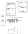
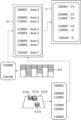
- FIG. 1 is a schematic diagram showing the overall configuration of a casino according to the first embodiment of the present invention.
- FIG. 2 is a perspective view of the gaming chip according to the first embodiment of the invention.
- FIG. 3 is a block diagram showing the configuration of the gaming chip management system according to the first embodiment of the invention.
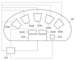
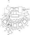
- FIG. 4 is a schematic diagram showing the configuration of the game table according to the first embodiment of the present invention.
- FIG. 5 is a diagram showing how the gaming chip is moved according to the first embodiment of the present invention.
- FIG. 6 is a diagram showing an example of data in the chip management database updated by the first method of managing movement of gaming chips according to the first embodiment of the present invention.
- FIG. 7 is a diagram showing an example of data in the chip management database updated by the second method of managing movement of gaming chips according to the first embodiment of the present invention.
- FIG. 8 is a diagram showing an example of data in the chip management database updated by the fourth method of managing movement of gaming chips according to the first embodiment of the present invention.
- FIG. 9 is a diagram showing an example of data in the chip management database updated by the fifth method of managing movement of gaming chips according to the first embodiment of the present invention.
- FIG. 10 is a diagram showing an example of data in the chip management database updated by the fourth method of managing movement of gaming chips according to the first embodiment of the present invention.
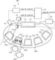
- FIG. 11 is a diagram showing the configuration of a management system according to the second embodiment of this invention.
- FIG. 12 is a diagram for explaining image recognition in an image captured by the camera according to the second embodiment of the present invention.
- FIG. 13A is a diagram showing another example of the gaming chip according to the second embodiment of the invention.
- FIG. 13B is a diagram showing still another example of the gaming chip according to the second embodiment of the invention.
- FIG. 14 is a diagram showing an example of an image captured by the camera according to the second embodiment of the invention.
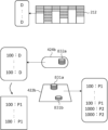
- FIG. 15 is a table showing an example of data stored in the database according to the second embodiment of the invention.
- FIG. 16 is a diagram showing an overall outline of a fraud detection system in a game arcade having a plurality of game tables according to the third embodiment of the present invention.
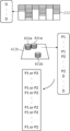
- FIG. 17A is a diagram showing details of a chip tray according to the third embodiment of the invention.
- FIG. 17B is a diagram showing another example of the chip tray according to the third embodiment of the invention.
- FIG. 18 is an enlarged view of a mark explaining dirt on a card ascertained in the third embodiment of the present invention.
- FIG. 19 is an explanatory diagram showing a simplified image of the exchange state of bills and chips grasped in the third embodiment of the present invention.
- FIG. 20 is an explanatory diagram showing how the dealer collects the chips won by the casino in the baccarat game according to the third embodiment of the present invention.
- FIG. 21 is an explanatory diagram showing how the dealer makes payments to the winning customers (game participants) in the baccarat game according to the third embodiment of the present invention.
- FIG. 22 is an explanatory diagram showing how winning customers (game participants) receive chips and payments in a baccarat game according to the third embodiment of the present invention.
- FIG. 23A is an explanatory diagram of an image to be subjected to image analysis of collection of chips won by the casino by the dealer in the fraud detection system according to the third embodiment of the present invention.
- FIG. 23B is an explanatory diagram of an image to be subjected to image analysis of collection of chips won by the casino by the dealer in the fraud detection system according to the third embodiment of the present invention.
- FIG. 23C is an explanatory diagram of an image to be subjected to image analysis of recovery of chips won by the casino side by the dealer in the fraud detection system according to the third embodiment of the present invention.
- FIG. 23A is an explanatory diagram of an image to be subjected to image analysis of collection of chips won by the casino by the dealer in the fraud detection system according to the third embodiment of the present invention.
- FIG. 23B is an explanatory diagram of an image to be subject
- FIG. 24 is an explanatory diagram of an image to be subjected to image analysis of fraudulent collection of chips in the fraud detection system according to the third embodiment of the present invention.
- FIG. 25A is an explanatory diagram of an image to be subjected to image analysis of collection of chips won by a game participant in the fraud detection system according to the third embodiment of the present invention.
- FIG. 25B is an explanatory diagram of an image to be subjected to image analysis of collection of chips won by a game participant in the fraud detection system according to the third embodiment of the present invention.
- FIG. 25C is an explanatory diagram of an image to be subjected to image analysis of collection of chips won by a game participant in the fraud detection system according to the third embodiment of the present invention.
- FIG. 25A is an explanatory diagram of an image to be subjected to image analysis of collection of chips won by a game participant in the fraud detection system according to the third embodiment of the present invention.
- FIG. 25B is an explanatory diagram of an image to be subjected to image
- FIG. 25D is an explanatory diagram of an image to be subjected to image analysis of collection of chips won by a game participant in the fraud detection system according to the third embodiment of the present invention.
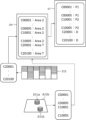
- FIG. 26 is a diagram showing the configuration of the management system of the first example of the fourth embodiment of this invention.
- FIG. 27 is a diagram illustrating an example of update of variation information in the first example of the fourth embodiment of this invention.
- FIG. 28 is a diagram illustrating an example of update of variation information in the first example of the fourth embodiment of this invention.
- FIG. 29 is a diagram illustrating an example of update of variation information in the first example of the fourth embodiment of this invention.
- FIG. 30 is a diagram showing the configuration of the management system of the second example of the fourth embodiment of this invention.
- FIG. 31 is a diagram showing the configuration of the management system of the third example of the fourth embodiment of this invention.
- FIG. 32 is a diagram illustrating an example of database update in the third example of the fourth embodiment of this invention.
- FIG. 33 is a diagram illustrating an example of database update in the third example of the fourth embodiment of this invention.
- FIG. 34 is a diagram illustrating an example of database update in the third example of the fourth embodiment of this invention.
- FIG. 35 is a diagram showing the configuration of the management system of the fourth example of the fourth embodiment of this invention.
- FIG. 36 is a diagram showing the configuration of the management system of the fifth example of the fourth embodiment of this invention.
- FIG. 37 is a diagram showing the configuration of the management system of the sixth example of the fourth embodiment of this invention.
- FIG. 38 is a diagram illustrating an example of update of variation information in the sixth example of the fourth embodiment of this invention.
- FIG. 39 is a diagram illustrating an example of update of variation information in the sixth example of the fourth embodiment of this invention.
- FIG. 40 is a diagram illustrating an example of update of variation information in the sixth example of the fourth embodiment of this invention.
- FIG. 41 is a diagram illustrating an example of update of variation information in the sixth example of the fourth embodiment of this invention.
- FIG. 42 is a diagram showing the configuration of the management system of the seventh example of the fourth embodiment of this invention.
- FIG. 43 is a diagram illustrating an example of database update in the seventh example of the fourth embodiment of this invention.
- FIG. 44 is a diagram illustrating an example of database update in the seventh example of the fourth embodiment of this invention.
- FIG. 44 is a diagram illustrating an example of database update in the seventh example of the fourth embodiment of this invention.
- FIG. 45 is a diagram illustrating an example of database update in the seventh example of the fourth embodiment of this invention.
- FIG. 46 is a diagram illustrating an example of database update in the seventh example of the fourth embodiment of this invention.
- FIG. 47 is a diagram illustrating an example of database update in the seventh example of the fourth embodiment of this invention.
- FIG. 48 is a diagram showing the configuration of the management system of the eighth example of the fourth embodiment of this invention.
- FIG. 49 is a diagram showing the configuration of the management system of the ninth example of the fourth embodiment of this invention.
- FIG. 50 is a diagram illustrating an example of updating variation information in the ninth example of the fourth embodiment of this invention.
- FIG. 51 is a diagram illustrating an example of update of variation information in the ninth example of the fourth embodiment of this invention.
- FIG. 52 is a diagram illustrating an example of update of variation information in the ninth example of the fourth embodiment of this invention.
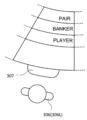
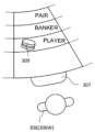
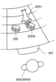
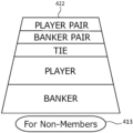
- FIG. 53 is a diagram showing an example of a bet area in the eleventh example of the fourth embodiment of this invention.
- FIG. 54A is a diagram showing another example of the betting area in the eleventh example of the fourth embodiment of this invention.
- FIG. 54B is a diagram showing another example of the bet area in the eleventh example of the fourth embodiment of this invention.
- Gaming chips are brought into the casino through a cage in the casino, and gaming chips to be discarded are also taken out of the cage.
- Conventional gaming chip tracing systems cannot always monitor the movement of all gaming chips within a casino, including movement of gaming chips within cages and movement between cages and locations within the casino.
- the present embodiment provides a cage system for monitoring movement of gaming chips in the cage and movement between the cage and each location in the casino, and a cage system including the system for managing gaming chips in the casino. gaming chip management system.
- a cage system is a cage system that manages movement of gaming chips within a cage of a casino hall, the cage is divided into a plurality of locations including cashiers, and the gaming chips have chip IDs.
- the cage system comprises first reading means for reading the chip ID from the RFID tag of the gaming chip moving between the plurality of locations; a second reading means for reading the chip ID from the RFID tag of the gaming chip, and a record for recording the chip ID read by the first reading means and the second reading means as a movement history of the gaming chip. means.
- the recording means may record the destination and/or origin of movement together with the chip ID in the movement history. With this configuration, it is possible to ascertain whether the movement is being performed accurately.
- the above cage system may further comprise management means for determining whether or not the movement is appropriate based on the movement history. With this configuration, inappropriate movement can be detected.
- the management means records, in the recording means, that the gaming chip has a movement history that does not match a predetermined possibility of movement history, indicating that it is illegal or suspected to be illegal. good.
- the above cage system may further comprise third reading means for reading the chip ID from the RFID tag of the gaming chip entering the cage from the casino hall. This configuration allows full control over the gaming chips in the cage.
- the management means provides an alert when the destination is recorded in the history of movement of the gaming chips leaving the casino hall and the gaming chips are not received at the destination. may be issued or recorded. With this configuration, it can be detected that movement from the cage to a predetermined location in the casino hall has not been completed normally.
- the management means may issue the alert or make the record when the gaming chip is not received at the destination within a predetermined time.
- a gaming chip management system includes any one of the cage systems described above and fourth reading means installed on a game table for reading the chip ID from the RFID tag of the gaming chip. are doing. With this configuration, it is possible to manage gaming chips in a casino hall containing cages.
- the management means may calculate the total amount of gaming chips owned by the player in the casino hall. With this configuration, it is possible to grasp the total liability of the casino in real time.
- the management means may record date and time information in the movement history. With this configuration, the movement history can be recorded in more detail.
- the management means may detect suspicious movement of the gaming chips based on the date and time information. With this configuration, various suspicious movements can be detected.
- the management means may record information about staff involved in the movement in the movement history. This configuration allows identification of the staff involved in any inappropriate movement.
- FIG. 1 is a schematic diagram showing the overall configuration of a casino according to the first embodiment of the present invention.
- a casino hall 1 is provided with a cage 10 and a plurality of game tables 42-45.
- the floor on which the game tables 42-45 are provided may be divided into a VIP floor and a public floor.
- Cage 10 is a room that only security staff can enter.
- Cage 10 is divided into vault 11 , main bank chamber 12 , F/C bank chamber 13 and cashier chamber 14 .
- the vault 11 is provided with a gate 21 leading to the outside of the cage 10, a gate 22 is provided between the vault 11 and the main bank chamber 12, and a gate 22 is provided between the main bank chamber 12 and the F/C bank chamber 13.
- a gate 23 is provided, a gate 25 is provided between the main bank room 12 and the cashier room 14, and the F/C bank room 13 has a gate leading to the casino hall 1 in which game tables 42 to 45 are placed. 24 are provided.
- Gates (windows) 26 to 28 leading to the casino hall 1 are provided in the cashier room 14 .
- Each of the gates 21 to 25 may allow the passage of people and gaming chips, or may allow only gaming chips to pass through and may be provided with a separate door for the entry and exit of people. Windows 26-28 are open to the extent that gaming chips can be exchanged for cash.
- a vault staff 31 is arranged in the vault 11, a main bank staff 32 is arranged in the main bank room 12, and an F/C bank staff 33 is arranged in the F/C bank room 13, In the cashier room 14, cashier staffs 34-36 are arranged corresponding to the windows 26-28.
- Game tables 42-45 are installed in the casino hall 1, and one dealer 52-55 is placed on each game table 42-45. Although only four game tables are shown in the example of FIG. 1, more game tables are actually arranged in the casino hall 1.
- FIG. A pit manager 56 is arranged for a plurality of adjacent game tables 42 .
- FIG. 1 there are players 61 to 69 in casino hall 1.
- a player in the casino hall 1 can purchase gaming chips or redeem gaming chips via any of the windows 26 to 28 like the player 61 shown in FIG.
- a player who has purchased gaming chips at the cage 10 can bet the gaming chips at the game tables 42 to 45 and enjoy the game.
- the dealer collects the gaming chips, and when the player wins the game, the dealer pays out according to the rules of the game and the bet amount. In this way, the number of gaming chips possessed by the player increases or decreases depending on the game.
- the player can purchase (buy-in) gaming chips at the cage 10 again. Also, the player can redeem (buy out) the gaming chips at the cage 10 when finishing playing.
- gaming chips are collected from the player who lost the game, and gaming chips are paid to the player who won the game.
- the number of gaming chips held by the dealer (casino) at the game table increases or decreases.
- a gaming chip carrying staff 51 receives gaming chips from the gate 24 of the F/C bank room 13, carries them to the game table, and replenishes the game table. Replenishing the gaming table with gaming chips in this way is also called "filling".
- the gaming chip carrying staff 51 carries the gaming chips from the game table to the cage 10 , and the gaming chips are stored in the F/C bank room 13 through the gate 24 . Returning the gaming chips from the game table to the cage 10 in this way is also called "credit".
- each room in the cage 10 and each game table are called locations.
- FIG. 2 is a perspective view of the gaming chip according to the first embodiment of the invention.
- a $100 gaming chip is shown in FIG.
- the gaming chip 70 has a disk shape, and a denomination (“$100” in FIG. 1) is indicated on both sides.
- a plurality of layers are laminated in the order of a white layer, a colored layer, and a white layer in the thickness direction, and a striped pattern is formed by sandwiching the colored layer between the white layers on the side surface.
- the color of the colored layer differs depending on the denomination, and therefore the denomination of the chip can be determined by determining the color of the colored layer.
- An RFID tag 71 is embedded inside the gaming chip 70 .
- the RFID tag 71 stores information on the chip ID and denomination of the chip.
- the RFID tag 71 may be writable, in which case the current location or owner information of the gaming chip may be recorded in the RFID tag 71, and the past location or owner information may be recorded on the RFID tag 71. history may be recorded.
- the gaming chip 70 may be configured by press-bonding a plurality of plate materials, or may be configured by resin molding.
- FIG. 3 is a block diagram showing the configuration of the chip management system according to the first embodiment of the present invention.
- a chip management system 1000 comprises a cage system 501 and a plurality of table systems 502 .
- a table system 502 is provided for each game table.
- the cage system 501 includes a chip management computer 100 and a chip management database 101 for integrally managing chips in the cage 10 and in the casino hall 1 .
- the cage system 501 also includes a vault computer 111 installed in the vault 11, and a vault card reader 112 and a vault chip reader 113 connected thereto.
- the cage system 501 also includes a main bank computer 121 installed in the main bank room 12, and a main bank card reader 122 and a main bank chip reader 123 connected thereto.
- the cage system 501 also has an F/C bank computer 131 installed in the F/C bank room 13, and an F/C bank card reader 132 and an F/C bank chip reader 133 connected thereto.
- the cage system 501 also includes a cashier computer 141 installed corresponding to each of the windows 26 to 28 in the cashier room 14, and a cashier card reader 142 and a cashier chip reader 143 connected thereto.
- the table system 502 comprises a table computer 151, a table card reader 152, a collection table chip reader 1531, a payout table chip reader 1532, a chip tray chip reader 154, and a plurality of betting area chip readers 155 connected thereto. . Although only one table system 502 is shown in FIG. 3, a plurality of table systems 502 are provided corresponding to a plurality of game tables.
- the above-mentioned "reader” includes an antenna, and a reading device that controls the antenna to transmit radio waves to the RFID tag and decodes the signal received by the antenna to acquire the information of the RFID tag. is.
- Vault computer 111 , main bank computer 121 , F/C bank computer 131 , cashier computer 141 , table computer 151 , and tip management database 101 are each connected to tip management computer 100 .
- the chip management computer 100, other computers, and the chip management database 101 may be connected by wire or wirelessly via a local network.
- the chip management computer 100 and the chip management database 101 may be installed on a wide area network (for example, the Internet) and connected to other computers via the wide area network. That is, the chip management computer 100 and the chip management database 101 may be installed in the cloud rather than in the casino.
- An input device (not shown) is connected to each of the computers 100, 111, 121, 131, 141, and 151 for receiving operation input by the corresponding staff.
- Input devices are, for example, keyboards, mice, buttons, touch pads, touch panels, and voice input devices.
- the functions of each computer may be integrated into the chip management computer 100, leaving only these input devices and communication devices at their corresponding locations.
- various signals (for example, an input signal input to the input device, a signal read by the chip reader, etc.) can be directly exchanged between the input device, card reader, chip reader, and the chip management computer 100 at each location. ) may be transmitted.
- the card readers 112, 122, 132, 142, 152 at each location read staff IDs or player IDs from ID cards possessed by staff or players. Specifically, vault card reader 112, main bank card reader 122, and F/C bank card reader 132 read the staff ID from the corresponding staff ID card, and cashier card reader 142 reads the staff ID from the cashier staff ID card. Along with reading the staff ID, the player ID of the player who purchases the gaming chips at the cashier or redeems the gaming chips is read. The table card reader 152 also reads the staff ID of the corresponding dealer and the player ID of the player who plays.
- the chip readers 113 , 123 , 133 , 143 , 153 , 155 at each location read information from the RFID tag 71 of the gaming chip 70 and write information to the RFID tag 71 .
- each of the chip leaders 113, 123, 133, 143, 153 when the gaming chip 70 moves from another location to the location and when the gaming chip moves from the location to another location (that is, the (when the gaming chip 70 leaves the location), the RFID tag 71 is read.
- FIG. 4 is a schematic diagram showing the configuration of the game table according to the first embodiment of the present invention.
- FIG. 4 illustrates the game table 42 .
- a game table 42 is provided with a plurality of play positions.
- the game table 42 has, on its table surface, a plurality of betting areas corresponding to a plurality of playing positions, a chip tray for accommodating the chips of the dealer, and a dealer area for reading and writing information to and from the RFID tag 71 of the gaming chip 70. and an ID card area for reading the ID cards of the dealer and players.
- the chip tray is provided with a chip tray antenna 514 for reading the RFID tag 71 of the gaming chip 70 housed therein.
- Each of the plurality of betting areas is provided with betting area antennas 515a to 515e inside the table surface for reading the RFID tags 71 of the gaming chips 70 placed there.
- a collection dealer antenna 5131 and a payout dealer antenna 5132 for reading the RFID tag 71 of the gaming chip 70 placed there are provided inside the table surface.
- An ID card antenna 512 is provided inside the table surface in the ID card area.
- Each of the antennas 512 to 515 is connected to the table computer 151 and transmits read signals to the table computer 151.
- the table computer 151 acquires various information stored in the RFID tag 71 or ID card by decoding the signal from each antenna.
- the staff assigned to each location will have their card ID read by the corresponding card reader before going to work.
- the computer at each location transmits the read staff ID and the date and time to the chip management computer 100 .
- the tip management computer 100 stores the staff ID read by the card reader of each location in the tip management database 101 together with the location and date information.
- the chip management database 101 stores a player table, chip table, game table table, staff table, and movement history table.
- the player table stores registration information of the player.
- the player table records player IDs, various player attributes, and player statuses such as VIP, suspicion, and blacklist for each player.
- the chip table records chip ID, denomination, type, manufacturing information, and chip status such as valid, missing, stolen, and invalid.
- a table ID, a game type, and the like are recorded in the game table table.
- the staff table records staff IDs, attributes of various staff members, and the like.
- the movement history table records the location of the gaming chip 70 or the history of the owner.
- FIG. 5 is a diagram showing how the gaming chip is moved according to the first embodiment of the present invention. As shown in Figure 5, each location, except the vault, has the potential for multiple sources of movement when gaming chips are coming in, and multiple destinations when leaving. There is a possibility of The chip management system of this embodiment recognizes these movements. For that purpose, the following several techniques can be adopted.
- First method In the first method, when a gaming chip 70 arrives at a computer at each location, the source of the movement is specified in the computer at the location, and the specified chip ID and the chip ID of the incoming gaming chip 70 are used for chip management. When the gaming chip 70 moves out from each location, the computer 100 reports to the chip management computer 100 the information of the location, that is, the information of the movement source and the chip ID of the gaming chip 70 .
- the main bank computer 121 reads the chip ID of the gaming chip 70 with the main bank chip reader 123 and reads the chip ID. It also reports to the chip management computer 100 that it will leave the main bank chamber 12 together. The chip management computer 100 updates the chip management database 101 according to this report.
- the F/C bank staff 33 operates the input device of the F/C bank computer 131 to transfer the gaming chip 70 to the main bank.
- the chip ID of the gaming chip 70 is read by the F/C bank chip reader 133 while inputting the designation that the gaming chip 70 came from the room 12 (moving source).
- the F/C bank computer 131 reports to the chip management computer 100 the specification that the transfer source is the main bank chamber 12 together with the read chip ID.
- the chip management computer 100 updates the chip management database 101 according to this report.
- FIG. 6 is a diagram showing an example of data in the chip management database updated by the first method of managing movement of gaming chips according to the first embodiment of the present invention.
- the example of FIG. 6 shows the movement history of the gaming chip 70 whose chip ID is "24825".
- the chip management database 101 stores chip ID 601, entry/exit information 602, source information 603, destination information 604, and date/time 605 of the gaming chip 70 as information on the movement history of the gaming chip 70.
- the information of the movement source is obtained (history H61), and for the gaming chip 70 entering the location, Since the information on the source and destination of the movement is obtained (history H62), it is confirmed that the gaming chip 70 has certainly left the main bank room 12 and has been received in the F/C bank room 13 based on the history H61 and H62. I can confirm.
- the dealer reads the chip ID of the gaming chip 70 with the table chip reader 153 of the game table, , and designates the F/C bank room 13 as the destination (designates credit).
- the table computer 151 reports to the chip management computer 100 the chip ID, the F/C bank room 13 as the transfer destination, and the table ID of table-4 as the transfer source.
- the chip management computer 100 updates the chip management database 101 according to this report.
- the F/C bank staff 33 reads the chip ID of this gaming chip 70 with the F/C bank chip reader 133 .
- the F/C bank computer 131 reports to the chip management computer 100 that the read chip ID and the F/C bank chamber 13 are entered.
- the chip management computer 100 updates the chip management database 101 according to this report.
- FIG. 7 is a diagram showing an example of data in the chip management database updated by the second method of managing movement of gaming chips according to the first embodiment of the present invention.
- the example of FIG. 7 also shows the movement history of the gaming chip 70 whose chip ID is "24825".
- the chip management database 101 stores chip ID 601, entry/exit information 602, source information 603, destination information 604, and date/time 605 of the gaming chip 70 as information on the movement history of the gaming chip 70.
- the gaming chip 70 leaving the location the information of the movement source and the movement destination is obtained (history H71), and the gaming chip 70 entering the location is obtained. Since the information on the destination is obtained (history H72), it is confirmed that the gaming chip 70 has certainly left the table-4 and has been received in the F/C bank room 13 based on the history H71 and H72. can.
- a third method is a combination of the first and second methods. That is, in the computer at each location, when the gaming chip 70 enters, the source is specified, and when the gaming chip 70 leaves, the destination is specified.
- the staff at each location uses the input device of the computer at each location to specify whether the gaming chip 70 is going out or coming in, and the chip of the gaming chip 70 read by the chip reader. The designation is reported to the chip management computer 100 together with the ID.
- the tip management computer 100 updates the entry/exit information and location information in the tip management database 101 based on this report.
- FIG. 8 is a diagram showing an example of data in the chip management database updated by the fourth method of managing movement of gaming chips according to the first embodiment of the present invention.
- the chip management database 101 stores a chip ID 601, entry/exit information 602, location information 606, and date/time 605 of the gaming chip as information on the movement history of the gaming chip 70 .
- the entry/exit information 602 and the location information 606 are recorded as shown in FIG. Received in room 12 can be confirmed.
- a fifth method records only the location information. That is, the staff at each location reads the chip ID of the gaming chip 70 with a chip reader at that location and reports it to the chip management computer 100 when the gaming chip 70 is at that location. The chip management computer 100 updates the chip management database 101 according to this report. The staff at each location may read the chip ID when the gaming chip 70 moves to the location, or may read the chip ID when the gaming chip 70 moves from the location. Alternatively, the chip ID may be read at arbitrary timing.
- FIG. 9 is a diagram showing an example of data in the chip management database updated by the fifth method of managing movement of gaming chips according to the first embodiment of the present invention.
- the chip management database 101 stores, as information on the movement history of the gaming chip 70, information on the chip ID 601, location information 606, and date and time 605 of the gaming chip.
- the gaming chip 70 Since the location information 606 is recorded as shown in FIG. 9 also by the fifth method, the gaming chip 70 has certainly come out of the vault 11 and received in the main bank room 12 based on the history H91 and history H92. can confirm that
- the movement of the gaming chip 70 within the cage 10 is performed using the fourth or fifth method, and the movement from the F/C bank chamber 13 to the game table is performed using the second method in which the destination is specified at the source.
- the first method of designating the movement source at the movement destination may be used.
- the cashier computer 141 reads the chip ID of the gaming chip 70 with the cashier chip reader 143 and reads the chip ID of the gaming chip 70 from the cashier card.
- the player ID is read from the ID card of the player by the reader 142, and the designation of the player who is the destination is reported to the chip management computer 100 together with the read chip ID.
- the chip management computer 100 updates the chip management database 101 according to this report.
- the cashier computer 141 reads the chip ID of the gaming chip 70 with the cashier chip reader 143 and reads the chip ID of the gaming chip 70 from the cashier card.
- the player ID is read from the ID card of the player by the reader 142, and the designation of the player who is the transfer source is reported to the chip management computer 100 together with the read chip ID.
- the chip management computer 100 updates the chip management database 101 according to this report.
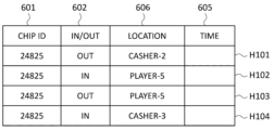
- FIG. 10 is a diagram showing an example of data in the chip management database updated by the fourth method of managing movement of gaming chips according to the first embodiment of the present invention.
- player-5 purchases gaming chips 70 at cashier-2 (history H101, H102), and then player-5 redeems the gaming chips 70 at cashier-3 (history H103, H102). H104).
- the entry/exit information 602 may be set to N/A, and only the information of the movement source (cashier) and the movement destination (player) may be recorded.
- the cashier staff when receiving the gaming chips 70 from the player, the cashier staff designates the reception, reads the chip ID of the gaming chips 70 using the cashier chip reader 143, and sends the gaming chips 70 to the player.
- the cashier chip reader 143 may be used to read the chip ID of the gaming chip 70 after designating the handing over.
- a player who has purchased the gaming chip 70 can play the game on the game table.
- the ID card of the player is first read by the table card reader 152 having the ID card antenna 512 .
- the player's playing position is specified. This makes it possible to recognize which player is in which betting area.
- the betting area antennas 515a to 515e combine a plurality of betting areas into one betting area without distinguishing between player positions, and use one or more antennas to read the gaming chips 70 placed in the one betting area. It may be an antenna. Also, the antenna in the betting area may be omitted.
- the chip tray antenna 514 reads the chip IDs of the gaming chips 70 accommodated in the chip tray before collection, and also reads the chip IDs of the gaming chips 70 accommodated in the chip tray after collection.
- the table computer 151 recognizes the chip ID of the gaming chip 70 newly brought into the chip tray (that is, collected from the player) by comparing the chip IDs of the chip trays before and after collection.
- the table computer 151 reports to the chip management computer 100 the chip ID read by the chip tray antenna 514 along with designation that the gaming chip 70 collected from the player is to be moved to the chip tray of the game table.
- the chip management computer 100 updates the chip management database 101 according to this report.
- the table computer 151 collects each bet gaming chip 70.
- the gaming chip 70 is stored in the chip management database 101 according to the determination. You may update the movement history to the effect of moving to. By such an update and the subsequent update to the effect that it has been received in the chip tray, it is possible to confirm whether the gaming chips 70 to be collected have certainly been collected in the chip tray.
- the chip tray continues to receive movement. If no history is recorded, it becomes clear that the gaming chips 70 to be collected have not been correctly collected.
- the chip ID read from the chip tray before and after collection is compared to grasp the chip ID newly brought into the chip tray due to collection.
- a collection chip area is specially provided to temporarily accommodate the chip tray collected in the tray, and an antenna independent of the other chip tray portions is provided in the collection chip area, so that the chip ID of the collected gaming chips 70 can be obtained. You may try to understand it.
- the chip ID of the gaming chip 70 to be collected is specified by having the collection dealer antenna 5131 read the RFID tag 71 in the collection area while the gaming chip 70 to be collected is being moved from the betting area to the chip tray.
- the player wins the game he/she receives a payout of gaming chips 70.
- the dealer first places the gaming chips 70 to be paid out to the player from the chip tray in the payout area of the game table.
- the payout dealer antenna 5132 reads the chip ID from the RFID tag 71 of the gaming chip 70 in the payout area. Since the table computer 151 knows which player is playing in each betting area, it associates the gaming chips 70 to be paid out with the players to be paid out (the location information of the gaming chips 70 to be paid out is linked to the relevant player). player).
- the method of identifying the chip ID of the gaming chip 70 to be paid out and linking it to the player is not limited to the above.
- the chip ID of the gaming chip 70 to be paid out may be specified and linked to the player who receives the payout.
- the chip ID of the gaming chip 70 may be read by the betting area antenna 515 of the betting area.
- the chip ID (linked to the player) of the wagered gaming chip 70 (linked to the player) is read together with the chip ID of the gaming chip 70 paid out (linked to the dealer or casino).
- the chip management computer 100 associates the chip ID of the gaming chip 70 that has been paid out with the player associated with the chip ID of the gaming chip 70 that has been bet.
- an antenna and a reading area for reading the RFID tag 71 of the gaming chip 70 to be paid out may be provided for each player position. Such antennas and reading areas may be placed between the betting area and the dealer at each player position. Also in this case, since it is known which player is at each player position, the gaming chips 70 to be paid out can be associated with the player ID. In this case, the dealer first places the gaming chips 70 to be paid out in the reading area of the corresponding player position, reads them with the antenna there, and then moves the gaming chips 70 to be paid out to the side of the betting chips in the betting area. Alternatively, the game chips 70 to be paid out placed by the dealer in the reading area may be taken by the corresponding player.
- the table computer 151 reports to the chip management computer 100 the combination of the chip ID of the gaming chips 70 to be paid out and the player ID of the player to be paid out. In response to this report, the chip management computer 100 updates the movement history in the chip management database 101 to the effect that the gaming chip 70 on the game table has been moved to the player.
- the RFID tag 71 of the gaming chip 70 taken out from the chip tray may be once read by the payout dealer antenna 5132 to specify the chip ID of the gaming chip 70 to be paid out.
- each movement history of each gaming chip 70 not only the location information but also the staff ID of the staff involved in the movement at that location may be recorded. .
- the location information is a player ID or a casino, the location information can also be called owner information.
- the status information of the gaming chip 70 may be recorded as "valid”, “invalid”, “missing”, “suspicious”, “non-exchangeable”, “non-playable”, and the like. Also, a flag may be used to indicate whether it is valid or invalid.
- each movement history record may have the chip ID of each gaming chip 70 as well as information on its denomination.
- the movement history of each gaming chip 70 can be recorded in the chip management database 101 by reading the chip ID at each location.
- the chip management computer 100 can implement various functions described below.
- the chip management computer 100 monitors the movement of the gaming chips 70 between the F/C bank room 13 and the game table and issues an alert if there is a problem. That is, the chip management computer 100 starts timing when it receives a report from the F/C bank computer 131 that a certain gaming chip 70 has moved out of the F/C bank room 13 with any game table as the destination. do. If the chip management computer 100 does not receive a report to the effect that the gaming chip 70 has been received from the table computer 151 of the destination game table within a predetermined time (for example, 5 minutes), it issues an alert.
- a predetermined time for example, 5 minutes
- This alert may be sent to the dealer of the game table in question, the pit manager managing the game table in question, or the like.
- the chip management computer 100 may update the status of the gaming chip 70 in the chip management database 101 to "missing", “not redeemable”, “not playable”, or the like.
- the chip management computer 100 when the chip management computer 100 receives a report from the F/C bank computer 131 that a certain gaming chip 70 has left the F/C bank room 13 after specifying one of the game tables as the destination, An alert may also be issued when a report to the effect that the gaming chip 70 has been received is received from the table computer 151 of a game table other than the game table designated as the destination. Also, in this case, the chip management computer 100 may update the status of the gaming chip 70 in the chip management database 101 to "wrong destination", "not redeemable”, "not playable”, or the like.
- the chip management computer 100 refers to the chip management database 101 and issues an alert if there is inappropriate gaming chip 70 movement.
- the movement of the gaming chip 70 is limited to the patterns shown in FIG. 5, and movement patterns other than these are inappropriate movements. Therefore, every time the chip management database 101 is updated, the chip management computer 100 determines whether or not the movement associated with the update is appropriate.
- the gaming chips 70 do not move directly from the vault 11 to the cashier room 14, and for example, do not move from the cashier room 14 to the player. If the gaming chips 70 are not collected at the game table and their movement history is found, the chip management computer 100 determines that the movement is inappropriate. Also, if the gaming chips 70 that are supposed to be in the possession of a certain player are exchanged by another player at the cashier, the possibility of money laundering is suspected. Thus, the chip management computer 100 detects inappropriate movement and issues an alert.
- the chip management computer 100 refers to the chip management database 101, extracts only the gaming chips 70 possessed by one of the players in the latest movement history information, and calculates the total amount thereof. By calculating, it has a function of calculating the total amount of gaming chips 70 possessed by all players at that point in time, that is, the casino's debt balance at that point of time.
- the total amount of player chips is the total amount of all gaming chips 70 on the cage 10 and the total amount of all gaming chips 70 on the game table from the total amount of all gaming chips managed by the chip management database 101. may be calculated as the amount after subtracting
- the chip management computer 100 refers to the chip management database 101, extracts the gaming chips 70 on each game table, and detects the number of chips for each denomination.
- the F/C bank computer 131 in the F/C bank room 13 and the F/C bank computer 131 and A notification may be issued to the table computer 151 of the game table. This notification specifies the number of gaming chips 70 to be replenished for each denomination or the total amount of gaming chips 70 to be replenished for each denomination.
- the chip management computer 100 extracts the gaming chips 70 on each game table by referring to the chip management database 101, and detects the total number of gaming chips 70 on the game table. . Then, when the total number is equal to or greater than a predetermined number close to the upper limit that can be accommodated in the game table, the F/C bank room 13 is instructed to collect (credit) the gaming chips 70 from the table.
- a notification may be issued to the bank computer 131 and the table computer 151 of the game table in question. This notification specifies the number of gaming chips 70 to be replenished for each denomination or the total amount of gaming chips 70 to be replenished for each denomination.
- a similar notification may be issued. For example, when the number of gaming chips 70 in a certain window of the cashier room 14 is low, a notification prompting the cashier computer 141 and the main bank computer 121 to replenish the cashier room 14 with gaming chips 70 is issued. you can
- a notification prompting the user to move is issued to both the destination and the source.
- the staff instructs the location computer via the input device whether or not to accept the move suggestion, and the location computer indicates that one of the destination and source locations is If the offer is accepted, the move order may be communicated to the other location.
- the F/C bank staff 33 uses the F/C bank chip reader 133 of the F/C bank room 13 to move it.
- the F/C bank computer 131 reports the read chip ID to the chip management computer 100 .
- the chip management computer 100 stores the chip IDs (transfer source chip IDs) of a plurality of gaming chips 70 related to fill, and refers to the chip management database 101 based on the report to acquire the denominations of those chip IDs.
- the chip management computer 100 grasps the transfer source chip ID, the total number of gaming chips 70 related to fill (transfer source total number), and the transfer source total amount based on the information from the F/C bank computer 131. It will be.
- the dealer When the gaming chip 70 is brought to the game table, the dealer reads the chip ID of the gaming chip 70 carried by the table chip reader of the game table, and the table computer 151 sends the read chip IDs to the chip management computer 100.
- the tip management computer 100 stores the plurality of tip IDs (destination tip IDs), refers to the tip management database 101 based on the report, acquires the denominations of the tip IDs, and sends them to Phil.
- the total amount (transfer destination total amount) of the gaming chips 70 is grasped.
- the chip management computer 100 based on the information from the table computer 151, grasps the destination chip ID, the total number of gaming chips 70 related to fill (movement destination total number), and the destination total amount. .
- the chip management computer 100 compares the source chip ID and the destination chip ID and determines whether they completely match. In addition, the tip management computer 100 compares the transfer source total amount and the transfer destination total amount, and determines whether or not they match. Further, the chip management computer 100 compares the total number of chips at the transfer source and the total number of chips at the transfer destination, and determines whether or not they match. If there is a discrepancy in any of the above comparisons, chip management computer 100 determines that the move was not performed correctly and issues an alert.
- the case of moving a plurality of gaming chips 70 from the game table to the F/C bank room 13 is as follows.
- the dealer uses the payout table chip reader 1532 of the game table to read the chip ID of the gaming chips 70 to be moved.
- the table computer 151 reports the read chip ID to the chip management computer 100 .
- the chip management computer 100 stores the chip IDs (transfer source chip IDs) of a plurality of gaming chips 70 related to credit, and refers to the chip management database 101 based on the report to acquire the denominations of those chip IDs. Then, the total amount of the gaming chips 70 related to the credit (total transfer amount) is grasped.
- the chip management computer 100 based on the information from the table computer 151, grasps the transfer source chip ID, the total number of gaming chips 70 related to credit (transfer source total number), and the transfer source total amount. .
- the F/C bank staff 33 reads the chip ID of the transported gaming chip 70 by the F/C bank chip reader 133, and the F/C bank computer 131 reports the read multiple chip IDs to the chip management computer 100 .
- the chip management computer 100 stores the plurality of chip IDs (destination chip IDs), refers to the chip management database 101 based on the report, acquires the denominations of the chip IDs, and converts them to credit.
- the total amount (transfer destination total amount) of the gaming chips 70 is grasped. Thereby, the chip management computer 100 grasps the transfer destination chip ID, the total number of gaming chips 70 related to the credit (transfer destination total number), and the transfer destination total amount based on the information from the F/C bank computer 131. It will be.
- the chip management computer 100 compares the source chip ID and the destination chip ID and determines whether they completely match. In addition, the tip management computer 100 compares the transfer source total amount and the transfer destination total amount, and determines whether or not they match. Further, the chip management computer 100 compares the total number of chips at the transfer source and the total number of chips at the transfer destination, and determines whether or not they match. If there is a discrepancy in any of the above comparisons, chip management computer 100 determines that the move was not performed correctly and issues an alert.
- the total amount and the total number may be calculated for each denomination amount of the gaming chips 70 and compared.
- the source total amount and the destination total amount may be calculated as "$600 in $10 chips, $400 in $100 chips".
- the tip management computer 100 when the tip management computer 100 notifies the transfer destination or the transfer source to prompt the transfer, the notification is compared with the total amount of the transfer source, the notification is compared with the total amount of the transfer destination, and the notification and the transfer are compared. By performing at least one of comparison with the original total number of sheets and comparison between the notification and the destination total number of sheets, it may be determined whether the movement has been performed correctly.
- the F/C bank chip reader 133 directs the gaming chips 70 toward the game table.
- the chip IDs of the gaming chips 70 carried by the F/C bank computer 131 are reported to the chip management computer 100 .
- the chip management computer 100 calculates the reported total amount of gaming chips 70 (fill total amount) by referring to the chip management database 101 .
- the chip management computer 100 refers to the chip management database 101, extracts the gaming chips 70 on the game table before the filling, and calculates the total amount (existing total amount). Then, the chip management computer 100 adds the total filled amount to the calculated existing total amount to calculate the theoretical total amount of the gaming chips 70 on the game table after filling (theoretical total amount after filling).
- the recovery table chip reader 1531 of the game table reads the chip ID of the brought gaming chip 70, and the table computer 151 reads the chip ID. Report to management computer 100 .
- the chip management computer 100 refers to the chip management database 101 for the reported chip ID, acquires the denomination, and calculates the actual total amount (actual filled total amount) of the gaming chips 70 in the chip tray.
- the table computer 151 The total amount of gaming chips 70 on the entire game table including the chip tray and such a storage area (but not including the player's gaming chips placed in the betting area) is calculated as the total amount after the actual fill.
- the chip management computer 100 compares the theoretical total amount after filling and the actual total amount after filling, and issues an alert if the two do not match. With this configuration, it is possible to confirm whether or not the amount of gaming chips 70 is correctly increased on the game table by Phil.
- the chip IDs of all the gaming chips 70 leaving the F/C bank room 13 are grasped, and on the game table, all the gaming chips 70 moved from the F/C bank room 13 Therefore, if the theoretical total amount after filling and the actual total amount after filling do not match, the chip ID of the gaming chip 70 that caused the mismatch can be grasped.
- the chip management computer 100 changes the status of the gaming chip 70 that caused the mismatch to a status such as "invalid", “non-exchangeable", or "non-playable”.
- the theoretical total amount after filling and the actual total amount after filling are compared.
- the theoretical total number of gaming chips 70 after filling theoretical total number after filling
- the actual total number of gaming chips 70 after filling total number after actual filling
- the payout table chip reader 1532 carries them toward the F/C bank room 13.
- the chip IDs of chips 70 are read and their chip IDs reported from table computer 151 to chip management computer 100 .
- the chip management computer 100 refers to the chip management database 101 to calculate the reported total amount of gaming chips 70 (total credit amount).
- the chip management computer 100 refers to the chip management database 101, extracts the gaming chips 70 on the game table before the credit, and calculates the total amount (existing total amount). Then, the chip management computer 100 subtracts the total credit amount from the calculated existing total amount to calculate the theoretical total amount (theoretical total amount after credit) of the gaming chips 70 on the game table after the credit.
- the chip tray chip reader 154 of the game table reads the chip ID of the gaming chip 70 stored at the game table,
- the table computer 151 reports to the chip management computer 100 .
- the chip management computer 100 refers to the chip management database 101 for the reported chip ID, obtains the denomination, and calculates the actual total amount (actual total amount after credit) of the gaming chips 70 in the chip tray.
- the table computer 151 The total amount of gaming chips 70 on the entire game table including the chip tray and such a storage area (but not including the player's gaming chips placed in the betting area) is calculated as the total amount after actual credits.
- the chip management computer 100 compares the theoretical total amount after credit and the actual total amount after credit, and issues an alert if the two do not match. With this configuration, it is possible to confirm whether the gaming chips 70 are correctly reduced on the game table by the credit.
- the chip IDs of all the gaming chips 70 transferred from the game table to the F/C bank room 13 are grasped, and in the F/C bank room 13 as well, all the gaming chips 70 transferred from the game table are identified. Therefore, when the theoretical total amount after credit and the actual total amount after credit do not match, the chip ID of the gaming chip 70 that caused the mismatch can be grasped.
- the chip management computer 100 changes the status of the gaming chip 70 that caused the mismatch to a status such as "invalid", “non-exchangeable", or "non-playable”.
- the theoretical total amount after credit and the actual total amount after credit are compared.
- excess It may be determined whether credit has been completed without deficit.
- the payout table chip reader 1532 by reading the gaming chips 70 carried to the F/C bank room 13 by the payout table chip reader 1532, the total amount of credit is grasped, and the existing total amount (the gaming chips 70 on the game table before the credit is executed) is read.
- the theoretical total post-credit amount was calculated by subtracting the total credit amount from the total amount of credits, the following may be substituted for this. That is, when the chip management computer 100 issues a notice prompting credit to the game table and the game table grants credit in response to this notice, the total amount of gaming chips 70 related to the credit specified in this notice
- the theoretical total amount after credit may be calculated by subtracting the total credit amount from the existing total amount, using the total number of sheets (which may be specified for each denomination amount) as the total credit amount.
- the chip management computer 100 After calculating the theoretical total credit amount, the chip management computer 100 compares the theoretical total amount after credit with the actual total amount after credit (actual total amount of gaming chips 70 after credit on the game table). , to see if a specified amount or number of gaming chips 70 have left the gaming table for credit.
- the door of the cage 10 is locked to prevent arbitrary intrusion of people, and the staff can enter and exit the room by satisfying the security conditions. In addition, similar entry/exit security is implemented between each room in the cage 10 .
- Staff working within the cage 10 are required to authenticate upon entering and leaving the cage 10 or assigned room.
- the chip management computer 100 verifies whether or not inappropriate gaming chips 70 have been moved since the staff entered the room until then when the staff is authenticated to leave.
- the chip management computer 100 cooperates with the locking system and does not permit exit if there is improper movement of the gaming chips 70 .
- the chip management computer 100 verifies whether or not there has been an inappropriate movement of the gaming chips 70 since the dealer arrived at the game table, and issues an alert if there is an inappropriate movement. do. Also, when the dealer changes, the chip management computer 100 checks whether there are gaming chips 70 that should be on the game table after the dealer leaves the table and before the next dealer comes to the table. That is, it verifies whether the dealer leaving the table has taken the gaming chip 70 out of the game table, and issues an alert if there is a problem.
- the gaming chips 70 may be stored in a place other than the chip tray on the game table.
- the chip trays may be doubled, the supplementary gaming chips 70 may be stored in the lower chip tray, and the supplementary gaming chips 70 may be stored in a cabinet provided on the game table.
- the gaming table is also equipped with an antenna for reading the RFID tags 71 of the gaming chips 70 so stored, and the table computer 151 reads the RFID tags 71 of all gaming chips 70 on the gaming table. should always be readable.
- the chip management computer 100 verifies the history of gaming chip purchases and redemptions for each player and issues alerts in the event of suspicious activity. For example, if a predetermined amount or more of gaming chips 70 are purchased and a predetermined amount or more of gaming chips 70 are exchanged for money within a predetermined period of time, such behavior is regarded as suspicious behavior and an alert is issued. In addition, if the gaming chip 70 is about to be converted into money without being used on the game table after the gaming chip 70 was purchased, and if the amount of the gaming chip 70 exceeds a predetermined amount, such an action is alerted as a suspicious action. is issued. Alternatively, an alert is issued for a player who purchases a predetermined amount of gaming chips 70 or more within a predetermined period of time as suspicious behavior.
- a gaming chip 70 may be enabled within the cage 10 .
- the chip management database 101 has a table storing chip IDs of valid gaming chips 70, and the chip management computer 100 reads the chip ID of the gaming chip 70 at the cashier or at the chip reader of the game table. Then, it verifies whether the chip ID is valid by referring to the table.
- the game chip 70 is brought out of the cage 10 after the invalidation process is performed within the cage 10 . Accordingly, even if the gaming chip 70 taken out of the cage 10 for disposal is stolen, such gaming chip 70 cannot be used at the cashier or the game table, thereby ensuring security.
- an unregistered player can purchase the gaming chip 70 and use the gaming chip 70 to play a game on the game table.
- a common anonymous player ID is used for unregistered players.
- the gaming chip 70 can be traced without interruption even if it moves to an unregistered player while the gaming chip 70 moves from place to place until it returns to the cage 10 after leaving the cage 10 . .
- a cashier window may be provided with a display device for displaying the total amount of gaming chips 70 and the result of verification of validity.
- the cashier staff puts the gaming chips 70 to be given to the player or the gaming chips 70 to be received from the player on the cashier chip reader 143 .
- the cashier chip reader 143 reads the denomination and status stored in the RFID tag 71 of the gaming chip 70 (usually a plurality).
- the cashier computer 141 displays the sum of the denomination amounts read by the cashier chip reader 143 on the display device. In addition to the total amount, the number of gaming chips 70 of each denomination may be displayed.
- the cashier computer 141 displays an error on the display device when there is a gaming chip 70 whose status is not valid among the read RFID tags 71, and displays when the status of all the gaming chips 70 is valid. Give the device a pass indication or nothing. In addition to the status, whether or not there has been an inappropriate movement history may be displayed. As a result, the gaming chips 70 can be delivered after the cashier staff and the player have agreed that the gaming chips to be given to the player or received from the player are valid and the total amount.
- the chip management computer 100 verifies whether the read chip ID is a valid chip ID. , the validity of the chip ID may be confirmed, and an alert may be issued when there is a problem.
- a table of valid chip IDs is recorded in the chip management database 101, and the chip management computer 100 refers to this table to verify whether the chip ID read at each location is valid. .
- the chip ID may be encrypted.
- the chip management computer 100 flags the relevant player, gaming chip 70, or movement history record as abnormal and may be recorded.
- the configuration of the rooms of the cage 10 is not limited to the one described above, and the number of rooms and the arrangement of the rooms may be arbitrary.
- the game table may be a table for playing baccarat, blackjack, or other card games, and may include locations for playing other games, such as roulette, in addition to the game table.
- Each of the above computers includes a processor and memory, and the processor executes a computer program stored in the memory to perform the above operations.
- the program may be provided to the computer by a non-temporary storage medium, or may be provided to the computer in the form of download. Communication between computers may be wired or wireless.
- each card reader reads an ID card to identify staff and players at each location. Staff and players may be specified.
- each room in the cage 10 and the game table are used as examples of locations to manage the movement of the gaming chip 70 between locations.
- the game table has a chip tray in which the dealer stores collected chips and pays out chips therefrom, a cabinet that stores gaming chips on the table, and a chip tray that consists of two stages.
- Each of the chip trays in the upper and lower stages of can be the locations of the above embodiments, and the movement of the gaming chips 70 between the respective locations can be managed in the same manner as described above.
- the chip ID, the total amount, and/or the total number of gaming chips 70 taken out from a cabinet of a certain game table are grasped, and the chip ID, the total amount, and/or the total number are kept in the chip tray of the game table for a predetermined time. You may make it issue an alert when it did not move inside. Further, for example, in a certain double chip tray, it is possible to detect that the gaming chips 70 taken out from the lower chip tray have moved to the upper chip tray, or that the gaming chips 70 taken out from the upper chip tray have moved to the lower chip tray. You can check it.
- the gaming chips 70 carried from the F/C bank room 13 to the game table are read using the dealer antenna 513, the bed area antenna 515, or the chip tray antenna 514.
- the chip tray is provided with a button so that the start and end of the filling operation can be recognized.
- the increased gaming chips 70 are recognized as filled gaming chips 70 .
- the gaming chips 70 carried to the F/C bank room 13 are read by the collection dealer antenna 5131, the payout dealer antenna 5132, the betting area antenna 515, or the chip tray antenna 514.
- the chip tray is provided with a button so that the start and end of the credit operation can be recognized, and the gaming chips 70 on the chip tray before credit and the gaming chips 70 after credit are compared to determine the amount of gaming reduced by credit.
- the chip 70 is recognized as a gaming chip 70 to be credited.
- the chip management computer 100 may be capable of outputting the chip inventory (chip ID) at each location (cage, chip tray, etc.).
- the chip management computer 100 may specify a past point in time and output the inventory at that point in time.
- an alert may be issued when a suspicious gaming chip (a gaming chip with a flag) is about to be redeemed at the cashier.
- the chip management database 101 may be able to store the redemption history of each player. Also, the chip management computer 100 may be capable of outputting the chip ID that the player should have.
- Information such as the chipset, casino information, location information, and the possibility of redemption may be written in the RFID tag 71 .
- information may be stored in the chip management database 101 in association with the chip ID.
- the chip management computer 100 or the computer at each location may check whether the gaming chip 70 should be at that location based on the information when the RFID tag 71 is read at that location.
- a set (chipset) of usable gaming chips 70 and types of gaming chips may be set for each area. For example, when the RFID tag 71 is read at a game table, the table computer 151 or the chip management computer 100 checks whether the chipset should be used at the game table.
- a gaming chip 70 that has been used for a certain number of years may be flagged in association with the chip ID.
- a gaming chip 70 that has passed a certain number of years from the start of use can be collected by identifying the location.
- a signal is output when the chip ID is detected at the cashier or at the game table.
- the table computer 151 or the chip management computer may issue a warning to the staff (monitor) when a player with potentially stolen gaming chips 70 arrives at the table.
- the cashier computer 141 or the chip management computer 100 detects chips that are purchased and then redeemed without being played in order to prevent money laundering.
- the cashier associates the player's photo with the chip ID when the amount of money above the threshold is exchanged or chips are purchased.
- a unique ID is given to anonymous players (players who do not have a member card) to trace chips. For anonymous players, their faces are photographed at the time of chip purchase, and the face image is associated with the player ID and registered in the chip management database 101. Afterwards, at each location (table, cashier, etc.), the player is identified by face recognition. An ID may be specified.
- Chip management computer 100 may invalidate the status of any chips associated with a blacklisted player.
- the chip management computer 100 associates a unique ID issued on the spot and/or a player ID associated with the gaming chip 70 when a player without a member card bets the gaming chip 70 at the game table.
- a play is recorded in the chip management database 101. - ⁇ At this time, the face image or the ID obtained by face recognition may be associated with the play. Further, when the member card is recognized later, the play record may be recorded in association with the member card ID.
- FIG. 11 is a diagram showing the configuration of a management system according to the second embodiment of this invention.
- the management system 2000 is a system that manages the gaming chip 70 on the game table 42 for playing a game using the gaming chip 70 containing the RFID tag 71 .
- the game table 42 includes a chip tray 421 for accommodating the dealer's gaming chips 70, betting areas 422a to 422e for placing gaming chips to bet on the game, and betting areas 422a to 422e and the chip tray 421. It has a collection area 423a and a payout area 423b. The collection area 423a and the payout area 423b are both located between the betting areas 422a to 422e and the chip tray 421.
- a recovery dealer antenna 5131 is embedded in the recovery area 423a for reading the RFID tag 71 of the gaming chip 70 recovered after losing the game in the recovery area 423a.
- a payout dealer antenna 5132 is embedded for reading, in the payout area 423b, the RFID tag 71 of the gaming chip 70 to be paid out to the player who won the game.
- the collection dealer antenna 5131 reads the RFID tag 71 of the gaming chip 70 before it is collected from the betting areas 422 a to 422 e and put into the chip tray 421 .
- the payout dealer antenna 5132 reads the RFID tag 71 of the gaming chip 70 before it is taken out from the chip tray 421 and paid out to the betting areas 422a to 422e.
- the chip tray 421 is provided with a chip tray antenna 514 for reading the RFID tag 71 of the gaming chip 70 housed in the chip tray 421.
- the collection dealer antenna 5131, the payout dealer antenna 5132, and the chip tray antenna 514 are connected to the first reader 81, respectively.
- the first reader 81 controls the collection dealer antenna 5131, the payout dealer antenna 5132, and the chip tray antenna 514, respectively, to transmit radio waves to the RFID tag 71, decode the signal received by each antenna, and read the RFID tag 71. Get information about In the present embodiment, the collection dealer antenna 5131, the dispensing dealer antenna 5132, and the chip tray antenna 514 are connected to the same first reader 81, so the first reader 81 is time-divisionally connected to the collection dealer antenna 5131. , payout dealer antenna 5132, and chip tray antenna 514 are respectively controlled to perform reading.
- the collection dealer antenna 5131, the payout dealer antenna 5132, and the chip tray antenna 514 may be connected to separate reading devices. In this case, reading by the collection dealer antenna 5131, the payout dealer antenna 5132, and the chip tray antenna 514 may be performed independently, and each antenna can perform reading at arbitrary timing.
- Bet area antennas 515a to 515e are embedded in the bet areas 422a to 422e, respectively.
- the betting area antennas 515a-515e read the RFID tags 71 of the gaming chips 70 placed on the respective betting areas 422a-422e.
- the bed area antennas 515a to 515e are connected to the second reader 82 respectively.
- Cameras 91 and 92 are installed on the game table 42 .
- the cameras 91 and 92 capture the gaming chips 70 placed on the bet areas 422a to 422e from different angles to generate images.
- Cameras 91 and 92 photograph the table surface of the game table 42 from obliquely above.
- Cameras 91 and 92 also photograph players participating in the game.
- the cameras 91 and 92 are connected to an image recognition device 83 respectively.
- the image recognition device 83 recognizes the position, type, and number of gaming chips 70 placed on the betting areas 422a to 422e by performing image recognition processing on the images generated by the cameras 91 and 92. Further, the image recognition device 83 performs image recognition processing on the images generated by the cameras 91 and 92 to generate a skeletal model of the player participating in the game. Note that the image recognition device 83 for recognizing the gaming chip 70 and the image recognition device 83 for generating the skeleton model of the player may be separate devices. Also, the camera that generates the image for recognizing the gaming chip 70 and the camera that generates the image for generating the skeleton model of the player may be separate cameras.
- the game table 42 is provided with an electronic shoe 94 as a card distribution device and a game result determination device.
- the electronic shoe 94 has a mechanism by which playing cards are pulled out one by one by the operation of the dealer.
- the electronic shoe 94 reads the rank of the drawn playing card. For this reason, the playing card is marked with a code mark indicating the rank, and the electronic shoe 94 is provided with an optical sensor for reading this code mark.
- the electronic shoe 94 is provided with a camera that captures the rank notation of the drawn playing card to generate an image, and an image recognition device that recognizes the rank notation by performing image recognition on this image. good too.
- the electronic shoe 94 is equipped with a processor that determines the game result according to the rules of the baccarat game based on the rank of the drawn playing cards.
- the electronic shoe 94 is also provided with buttons for the dealer to operate.
- game results such as player win, banka win, tie, player pair, banka pair, lucky 6, etc. are determined based only on the rank of the playing cards drawn out from the electronic shoe 94 in order.
- the electronic shoe 94 recognizes the button operation, recognizes the start or end of the game, and recognizes the rank of the playing cards drawn in one game and the drawing order.
- the game table 42 is further provided with a cash slot 93 for inserting cash.
- the cash slot 93 is provided with a cash sensor 931 for detecting cash passing therethrough.
- the management system 2000 further comprises a management device 84.
- the management device 84 is connected to the first reader 81 , the second reader 82 , the image recognition device 83 and the electronic shoe 94 .
- the management device 84 acquires the reading result of the RFID tag 71 of the gaming chip 70 by the first reading device 81 and the second reading device 82, the image recognition result by the image recognition device 83, and the game result by the electronic shoe 94. Based on this, the movement of the gaming chips 70 on the gaming table 42 is managed.
- the management device 84 determines whether or not the gaming chips 70 to be collected from the betting areas 422a to 422e have been collected from the betting areas 422a to 422e and read by the collection dealer antenna 5131. FIG. Specifically, the management device 84 determines whether or not the amount of the gaming chips 70 read by the collecting dealer antenna 5131 matches the amount to be collected. The management device 84 determines the amount to be collected based on the bet object, the bet amount, and the game result.
- the management system 2000 grasps the bet target and the bet amount.
- the bet target and bet amount are recognized using the cameras 91 and 92 and the image recognition device 83 .
- the image recognition device 83 determines bet objects and bet amounts of the gaming chips 70 bet on the betting areas 422a to 422e. In the betting areas 422a to 422e of each player position, player (P), banker (B), tie (T), player pair (PP), and banker pair (BP) are provided as bet objects.
- FIG. 12 is a diagram explaining image recognition in an image captured by the camera according to the second embodiment of the present invention.
- the example in FIG. 12 is an image captured by the camera 91 .
- An image 901 shows a betting area, gaming chips placed on the betting area, and a player.
- the image recognition device 83 performs image recognition processing for detecting gaming chips on the image 901 to detect gaming chips from the image 901 .
- a neural network can be used for this image recognition processing.
- the detected stack of gaming chips is surrounded by rectangular frames c1 and c2.
- the image recognition device 83 further detects the skeleton to generate skeleton models sm1 and sm2 of the player.
- the image recognition device 83 further performs face detection of the player to extract face areas f1 and f2.
- Neural networks can also be used for these skeleton detection and face detection.
- the image recognition device 83 determines the position where the gaming chip stack is placed, that is, the gaming Recognize the bet object on which the stack of chips is bet. As shown in FIG. 12, since the gaming chip that the player is moving is also recognized, the image recognition device 83 receives a signal indicating that the first playing card of the game has been pulled out from the electronic shoe 94. The game chip may be detected from the image at that time. At the timing when the first playing card is drawn out, the player cannot touch the bet gaming chips, and the positions of the gaming chips are fixed. As the image recognition processing, segmentation may be performed to specify the area of the stack of gaming chips. A betting object on which the stack of gaming chips is bet is recognized based on the position of the .
- the image recognition device 83 may further recognize the type of each gaming chip forming the stack by image recognition. As shown in FIG. 12, the side surface of the gaming chip 70 is provided with a colored layer indicating the denomination (type). , the type and number of gaming chips 70 included in the stack can be recognized.
- the type and number of gaming chips in each of the betting areas 422a-422e may be recognized by the betting area antennas 515a-515e and the second reader . That is, the positions (bet targets) of the gaming chips bet on the betting areas 422a to 422e are recognized by the cameras 91 and 92 and the image recognition device 83, and the types and numbers are determined by the betting area antennas 515a to 515e and the second reader. 82.
- the chip ID when the chip ID is written on the side surface of the gaming chip 70, the chip ID may be recognized by recognizing the images generated by the cameras 91 and 92 with the image recognition device 83.
- FIG. 13A is a diagram showing another example of the gaming chip according to the second embodiment of the invention
- FIG. 13B is a diagram showing still another example of the gaming chip according to the second embodiment of the invention.
- FIG. 4 is a diagram showing;
- the gaming chips 70′ and 70′′ have side IDs, which are identification information, written on the sides thereof.
- the side ID is represented by the presence or absence of a plurality of dots (dot pattern).
- the side ID is represented by the presence or absence of dots in a dot row consisting of 8 dots, so it is possible to represent 2 to the 8th power of information.
- the side ID is represented by a numeric string.
- the side ID may be represented by a matrix pattern, barcode, or character string.
- the side ID is represented within a range of 1 ⁇ 6 or less in the circumferential direction of the side surface of the gaming chip.
- a plurality of side IDs are written at predetermined intervals in the circumferential direction on the side surface of the gaming chip.
- the side ID may be a unique ID that uniquely identifies each gaming chip, or information indicating the group (e.g., value) to which each gaming chip belongs, that is, information that may overlap with other gaming chips. good too.
- the side ID when the side ID is represented by a string of numbers, the side ID may be a unique ID, and when the side ID is represented by a dot pattern (dot string), the side ID is information about the group to which it belongs. can be
- the side surfaces of the gaming chips 70' and 70'' are divided into three layers in the thickness direction.
- the first layer and the third layer have different colors according to the value of the gaming chip, and the second layer (center line) in the middle has any value regardless of the value of the gaming chip.
- Gaming chips are also a common color (eg, black).
- the side ID can be marked by printing or laser engraving.
- the gaming chips 70' and 70'' have built-in RFID tags.
- the RFID tag records at least a unique ID that uniquely identifies the gaming chip and information on the group (for example, value) to which the gaming chip belongs.
- the unique ID stored in the RFID tag and the unique ID written as the side ID are the same ID. Those two IDs may be associated in a database.
- the gaming chips 70' and 70'' have built-in capsules, and the RFID tags are accommodated in the capsules. Also, on the outside of the capsule, a decal is affixed with information on the value of the gaming chip, information on the casino where it is used, and the like.
- a unique ID that uniquely identifies the gaming chip is printed on the capsule. The unique ID printed on this capsule may be the same as or different from the unique ID stored in the RFID tag. If the unique ID printed on the capsule and the unique ID stored in the RFID tag are different, the unique IDs may be associated and stored in the database.
- a unique ID may be printed on the chip surface under the decal. Also, the unique ID may be printed on the surface of the chip with invisible ink such as UV ink or infrared absorbing ink.
- FIG. 14 is a diagram showing an example of an image captured by the camera according to the second embodiment of the present invention.
- multiple stacks of gaming chips placed on multiple betting areas are shown.
- the sides of the chip are also observable in the images of the cameras 91 and 92 .
- the image recognition device 83 receives the captured images generated by the cameras 91 and 92 and performs image recognition on them, thereby recognizing at least the position, type, and side ID information of each of the plurality of gaming chips. do.
- the image recognition device 83 performs image recognition at least partially using a neural network image recognition engine.
- the stack of gaming chips exists at an arbitrary location.
- the image recognition device 83 uses another neural network to extract the colored layer (center line) of each of the plurality of gaming chips from the extracted portion of the stack.
- the image recognition device 83 further determines the value of each gaming chip based on the extracted colors above and below the center line.
- the image recognition device 83 further reads the side ID from the center line portion, acquires the side ID information by decoding the dot pattern in the case of FIG. 13A, and decodes the number in the case of FIG. 13B. By doing so, the information of the side ID is acquired.
- FIG. 15 is a table showing an example of data stored in the database according to the second embodiment of the present invention.
- the database 85 stores information on the denomination (type), owner, and status for each chip ID represented by the side ID.
- the denominations are, for example, $10, $50, $100, $500, and the like.
- the player ID is stored as owner information
- the gaming chip 70 is owned by the casino, information indicating that the owner is the casino is stored.
- Information such as valid, invalid, and doubtful is stored as the status.
- the management device 84 can know the face value, owner, and status of each gaming chip 70. .
- the management device 84 calculates the total amount of gaming chips bet on each bet target, that is, the bet amount, based on the value and number of gaming chips recognized as described above.
- the management device 84 uses the cameras 91 and 92 and the image recognition device 83 to determine the amount of gaming chips bet on each betting target, or obtains the amount of gaming chips bet on each betting target.
- the device 83 is used to recognize the position of the gaming chip 70, and the bet area antennas 515a to 515e and the second reader 82 are used to recognize the bet amount of each of the bet areas 422a to 422e. Using the area antennas 515a to 515e and the second reader 82, the position, type, and number of gaming chips 70 can also be recognized.
- the management device 84 recognizes the bet objects and bet amounts in each of the betting areas 422a to 422e based on the information on the position, type, and number of bets obtained from the second reading device 82.
- the management device 84 determines the number of gaming chips 70 bet on each of the betting areas 422a to 422e based on the information on the betting objects and betting amounts recognized as described above and the information on the game result obtained from the electronic shoe 94. It is determined whether the stack has won or lost the game, the stack of gaming chips 70 that has lost is determined to be the stack to be collected, and the stack of gaming chips 70 that has won is determined at the redemption rate defined for the bet object. Based on this, the amount of gaming chips 70 to be paid out is obtained.
- the dealer When the game result is determined, the dealer first collects the losing gaming chips (that is, the losing bet) for each player. At this time, a stack of gaming chips 70 collected from a certain player (losing bet stack) is placed in the collection area 423a and read by the collection dealer antenna 5131. FIG. After that, the stack of gaming chips 70 is accommodated in the chip tray 421 . After that, another stack of gaming chips 70 (losing bet stack) is recovered and placed in the recovery area 423 a , read by the recovery dealer antenna 5131 , and stored in the chip tray 421 . This is done for all stacks of gaming chips 70 that have lost (losing bet stacks). At this time, the dealer collects the losing gaming chips 70 in the order of the player position (for example, in the order of the player position number).
- the management device 84 functions as recovery determination means, and the amount and chip ID of the gaming chips 70 read by the recovery dealer antenna 5131 in the recovery area 423a for each bet that loses the game are read in the betting areas 422a to 422e. Determines whether or not it matches the chip ID and the amount of the losing bet stack bet on either.
- the management device 84 sets the amount of the gaming chips 70 to be collected determined by the betting object, the bet amount, and the game result as the amount of the lost bet stack.
- the management device 84 uses the amount and chip ID of the gaming chips 70 that are no longer read from the bet areas 422a to 422e as the amount and chip ID of the losing bet stack and the amount and chip ID read in the recovery area 423a. It may be determined whether the
- the management device 84 determines that the increased amount of the gaming chips 70 in the chip tray 421 read using the chip tray antenna 514 is the total amount of the losing bet stack and the chip ID; That is, it is determined whether the total amount to be collected matches the chip ID. In addition, the management device 84 collects the increased amount of the gaming chips 70 in the chip tray 421 read using the chip tray antenna 514 and the added chip ID in the collection area 423a each time a losing bet stack is collected. It is determined whether the amount of gaming chips 70 read by the dealer antenna 5131 and the chip ID match the total amount and chip ID for all collections.
- the management device 84 obtains the total amount of the gaming chips 70 in the chip tray 421 read by the chip tray antenna 514 and the chip IDs before starting the collection, and completes the collection. After that, the total amount of gaming chips 70 in the chip tray 421 and the chip ID read again by the chip tray antenna 514 are obtained, and the difference between them is obtained to calculate the increased amount and the added chip ID.
- the collection operation by the dealer does not have to be the method of reading each stack in the collection area 423a and storing it in the chip tray 421 as described above. For example, one stack at a time may be moved to the collection area 423 a in order, and after collecting all the losing bet stacks in the collection area 423 a , they may be accommodated in the chip tray 421 . In this case, every time a newly collected gaming chip 70 is added to the collection area 423a, the management device 84 collects the added information based on the information read by the collection dealer antenna 5131. It may also be acquired as information of the gaming chip 70 .
- the collection order is known as described above. stack total and chip ID are also known.
- the management device 84 stores the known total amount and chip ID of the gaming chips 70 to be collected (to be read by the collection dealer antenna 5131) and the total amount and chip ID of the gaming chips 70 actually read by the collection dealer antenna 5131. is compared to determine whether collection was performed correctly.
- the management device 84 outputs or records the player position or player information of the bet stack involved in such fraudulent withdrawals, if the withdrawals are not performed correctly.
- the management device 84 functions as payout determination means, and determines whether or not the amount of gaming chips 70 to be paid out has been read by the payout dealer antenna 5132 for each bet that wins the game.
- the management device 84 regards the payout amount calculated from the bet amount of the winning gaming chips and the redemption rate defined for the bet object as the amount to be paid out, which is read by the payout dealer antenna 5132 in the payout area 423b. It is determined whether the amount of the gaming chip 70 matches. Also in the payout, if there are a plurality of winning bet stacks, the dealer pays out the gaming chips 70 in order of the player position (for example, in order of the player position number from the smallest).
- the management device 84 compares the known total amount with the total amount of gaming chips 70 actually read by the payout dealer antenna 5132 to determine if there is a mismatch. If so, identify and output or record the player position or player involved in the discrepancy.
- the management device 84 may further determine whether the amount of gaming chips added to the betting areas 422a to 422e matches the amount of gaming chips 70 read by the payout dealer antenna 5132 in the payout area 423b. . By this determination, it can be confirmed whether the gaming chips 70 placed in the payout area 423b have been paid to the correct player position.
- the management device 84 determines that the amount of decrease in the gaming chips 70 in the chip tray 421 read using the chip tray antenna 514 matches the total amount to be paid out. determine whether there is In addition, the management device 84 reads the reduced amount of gaming chips in the chip tray 421 read using the chip tray antenna 514 with the payout dealer antenna 5132 in the payout area 423b each time a winning bet stack is paid out. It is determined whether the amount of gaming chips 70 obtained matches the total amount for all payouts.
- the management device 84 acquires the total amount of the gaming chips 70 in the chip tray 421 read by the chip tray antenna 514 before starting the payout after all the collection is completed, and all After the payout is completed, the total amount of gaming chips 70 in the chip tray 421 read by the chip tray antenna 514 is obtained again, and the difference between them is obtained to calculate the amount of decrease.
- the management device 84 may determine whether or not the amount of increase/decrease calculated from the bet target, bet amount, and game result matches the actual amount of increase/decrease in the chip tray 421, or The amount of increase or decrease is obtained by adding or subtracting the total amount of gaming chips 70 read by the collection dealer antenna 5131 in the collection area 423a and the total amount of gaming chips 70 read by the payout dealer antenna 5132 in the payout area 423b. It may be determined whether the obtained increase/decrease amount matches the actual increase/decrease amount in the chip tray 421 .
- the management device 84 specifies the gaming chips 70 to be collected based on the bet target, the bet amount, and the game result, and the gaming chips 70 are read by the collection dealer antenna 5131 in the collection area 423a. Determine if the amount and/or chip ID of gaming chips 70 is the amount and chip ID to be collected. In addition, the management device 84 ensures that the amounts and/or chip IDs of the gaming chips 70 that cannot be read by the betting area antennas 515a to 515e of the betting area 422a are read by the collecting dealer antenna 5131 of the collecting area 423a. It is determined whether or not the amount and/or the chip ID of the gaming chip 70 match.
- the management device 84 stores the amount and/or the chip ID of the gaming chips 70 read by the collection dealer antenna 5131 in the collection area 423a as the amount and/or the chip ID of the gaming chips 70 added to the chip tray 421. Alternatively, it is determined whether or not it matches the chip ID.
- the management device 84 specifies the amount of gaming chips 70 to be paid out based on the bet target, the bet amount, and the game result, and the number of gaming chips 70 read by the payout dealer antenna 5132 in the payout area 423b. Determine whether the amount is the amount to be paid out. In addition, the management device 84 controls the amount of gaming chips 70 paid out from the chip tray 421 and decreased in the chip tray 421 and/or the amount of gaming chips 70 whose chip ID is read by the payout dealer antenna 5132. and/or determine whether it matches the chip ID.
- the management device 84 adds the gaming chip amount and/or the chip ID read by the payout dealer antenna 5132 of the payout area 423b to the betting areas 422a to 422e and adds them to the betting area antennas 515a to 515e. It is determined whether or not the amount and/or the chip ID of the gaming chip 70 read in .
- the management device 84 determines whether the exchange, that is, the equivalence exchange between the gaming chips presented by the player and the gaming chips presented by the dealer, has been correctly performed. For this reason, the management device 84 recognizes that the exchange transaction is being performed when the exchange is being performed.
- a currency exchange transaction is started when the player places his or her own gaming chips 70 requesting currency exchange in the collection area 423a and informs the dealer of the intention of currency exchange.
- the dealer puts gaming chips 70 equivalent (but different in denomination (type)) to the gaming chips presented by the player and placed in the collection area 423a in the payout area 423b. That is, in the exchange transaction, the gaming chips 70 paid out by the player exist in the collection area 423a, and the gaming chips 70 paid out by the dealer exist in the payout area 423b at the same time.
- the management device 84 detects the gaming chips 70 at the collection dealer antenna 5131 in the collection area 423a and the payout dealer antenna 5132 in the payout area 423b at the same time or at the same time within a predetermined time interval. , and the exchange mode is activated. In the exchange mode, when the management device 84 determines that an exchange transaction is being performed, the total amount of gaming chips 70 read in the collection area 423a and the total amount of gaming chips 70 read in the payout area 423b are displayed. By comparing and determining whether the two are equal, it is determined whether the exchange is performed correctly.
- the management device 84 determines whether the number of gaming chips 70 read in the collection area 423a is different from the number of gaming chips 70 read in the payout area 423b, and activates the exchange mode. Alternatively, it may be determined whether the exchange was performed correctly. In addition, the management device 84 refers to the database 85 for the gaming chip 70 read in the recovery area 423a, identifies the owner, confirms that it is any player ID, and then pays out the chip. The database 85 is referenced for the gaming chip 70 read in the area 423b to identify its owner, confirm that it is in the casino, activate the exchange mode, or confirm that the exchange has been properly performed. You can judge whether
- the recovery area 423a is the area in which the gaming chips 70 put out by the player are to be placed at the time of exchange
- the payout area 423b is the area in which the gaming chips 70 put out by the dealer are to be placed.
- the area where the gaming chips 70 paid by the player should be placed may be the payout area 423b
- the area where the gaming chips 70 paid by the dealer should be placed may be the collecting area 423a.
- the gaming chips 70 issued by the player are placed in the collection area 423a
- the gaming chips 70 issued by the dealer are placed in the payout area 423b
- the gaming chips 70 delivered by the player are placed in the payout area 423b.
- the gaming chips 70 provided by the dealer may be placed in the collection area 423a. That is, without fixing the places where the gaming chips 70 paid out by the player and the gaming chips 70 paid out by the dealer should be placed, one is placed in one of the collection area 423a and the payout area 423b, and the other is placed in the collection area 423a and the payout area. It may be placed on the other side of area 423b.
- the management device 84 may activate the exchange mode when it detects that the gaming chips 70 are present in the collection area 423a and the payout area 423b at the same time.
- the total amount of gaming chips 70 placed in the collection area 423a and the total amount of gaming chips 70 placed in the payout area 423b are compared, and the two are equal and/or the gaming chips placed in the collection area 423a are compared.
- the number of chips 70 and the number of gaming chips 70 placed in the payout area 423b are compared, and if the two are equal, it may be determined that the exchange mode has been activated or the exchange has been properly performed.
- the management device 84 compares the total amount of gaming chips 70 placed in the collection area 423a and the total amount of gaming chips 70 placed in the payout area 423b, and if the two do not match, the alert device 86 to output an alert. In addition, the management device 84 determines that the owner of the gaming chip 70 read in either the collection area 423a or the payout area 423b is one of the player IDs, and the other of the collection area 423a or the payout area 423b.
- the alert device 86 is controlled to output an alert. In this case, the alert device 86 specifically warns that there is no exchange between the player and the casino.
- the alert device 86 may include a voice output device and output an alert by sound, may include a lamp and output an alert by turning on the lamp, or may include a display device and output an alert on a display screen. good.
- the management device 84 starts the exchange mode when it detects that the gaming chips 70 are present in the collection area 423a and the payout area 423b at the same time.
- the exchange mode may be activated.
- the management device activates the exchange mode when it is detected that gaming chips 70 owned by a player and gaming chips 70 owned by a non-player are placed in the collection area 423a and the payout area 423b.
- the chip IDs of all the gaming chips 70 leaving the F/C bank room 13 are grasped, and on the game table 42, the F / Detect the chip IDs of all the gaming chips 70 moved from the C bank room 13 . This compares the theoretical chip ID and total amount of all gaming chips 70 to be filled with the chip ID and total amount of all gaming chips 70 actually filled.
- the dealer reads the RFID tag 71 of the filled gaming chip 70 moved from the F/C bank room 13 to the game table 42 with the recovery dealer antenna 5131 in the recovery area 423 a and then stores it in the chip tray 421 .
- the chip tray antenna 514 of the chip tray 421 reads the RFID tag 71 of the gaming chip 70 accommodated in the chip tray 421 after filling.
- the management device 84 acquires the chip IDs and the total amount of all the gaming chips 70 that have left the F/C bank room 13, and stores these together with the chip IDs and the total amount of the gaming chips 70 read by the recovery dealer antenna 5131. compare. Also, in the fill transaction, the management device 84 stores the chip IDs and the total amount of the RFID tags 71 of the gaming chips 70 placed in the recovery area 423 a and read by the recovery dealer antenna 5131 and the gaming chips 70 on the chip tray 421 . By being accommodated, the chip ID and total amount of the gaming chips 70 newly added to the chip tray 421 are compared.
- the management device 84 determines that there is a mismatch in any of these comparisons, it controls the alert device 86 to output an alert. In this case, the alert device 86 specifically warns that the fill transaction has not been performed correctly.
- the chip IDs of all the gaming chips 70 entering the F/C bank room 13 are grasped, and on the game table 42, the F / Detect the chip IDs of all gaming chips 70 that move to the C bank room 13 .
- the theoretical chip IDs and total amount of all credited gaming chips 70 are compared with the chip IDs and total amount of all actual credited gaming chips 70 .
- the management device 84 acquires the chip IDs and total amounts of all the gaming chips 70 entering the F/C bank room 13, and compares these with the chip IDs and total amounts of the gaming chips 70 read by the payout dealer antenna 5132. do. Also, in a credit transaction, the management device 84 stores the chip ID and total amount of the RFID tags 71 of the gaming chips 70 placed in the payout area 423b and read by the payout dealer antenna 5132, By removing, the chip ID and total amount of the gaming chips 70 reduced from the chip tray 421 are compared.
- the management device 84 determines that there is a mismatch in any of these comparisons, it controls the alert device 86 to output an alert. In this case, the alert device 86 specifically warns that the credit transaction has not been performed correctly.
- the management device 84 sets the period after the game result is finalized and all settlements are completed and before the first playing card of the next game is withdrawn from the electronic shoe 94 as a fill transaction. and an inter-game period during which credit transactions may occur. During this period, the management device 84 reads the RFID tag 71 of the gaming chip 70 at the collection dealer antenna 5131 in the collection area 423a during the inter-game period. If not, it recognizes it as a fill transaction and activates fill mode.
- the management device 84 determines that the RFID tag 71 of the gaming chip 70 is read by the payout dealer antenna 5132 in the payout area 423b during the inter-game period, the exchange condition is not satisfied, and the chip buy-in condition described later is satisfied. If not satisfied, it is recognized as a credit transaction and the credit mode is activated.
- the amount of gaming chips 70 to be filled or credited may be specified in the management device 84 by the operator manually inputting the amount. In this case, the management device 84 determines whether or not the total amount of gaming chips 70 read in the collection area 423a or the payout area 423b is the specified amount.
- the player can purchase the gaming chips 70 at the cashier as described in the first embodiment, and can also purchase the gaming chips 70 from the dealer at the game table 42 .
- the dealer receives cash from the player, throws it into the cash slot 93, and gives the player gaming chips 70 equivalent to the cash.
- the dealer places the gaming chip 70 to be paid out to the player in the payout area 423 b , and the payout dealer antenna 5132 reads the RFID tag 71 of this gaming chip 70 .
- the cash sensor 931 provided in the cash slot 93 detects cash, it notifies the management device 84 of this.
- the management device 84 receives notification of cash detection from the cash sensor 931 and activates the chip buy-in mode.
- the management device 84 determines the chip ID and total amount of the gaming chips 70 read by the payout dealer antenna 5132. The management device 84 further compares the chip ID and the total amount of the gaming chips 70 removed from the chip tray 421 by this chip buy-in with the chip ID and the total amount of the gaming chips 70 read by the payout dealer antenna 5132, and finds a mismatch. If there is, the alert device 86 is controlled to output an alert.
- the cash sensor 931 only detects the presence of cash in the cash slot 93, but instead of the cash sensor 931, it may have a function to determine the denomination (amount) and authenticity of the cash.
- the management device 84 may determine whether the total amount of cash detected by the cash sensor 931 matches the total amount of gaming chips 70 placed in the payout area 423b. may control the alert device 86 to output an alert.
- the cash paid out by the player in the chip buy-in may be recognized by the cameras 91 and 92 and the image recognition device 83 .
- the management device 84 may compare the recognized total amount of cash with the total amount of gaming chips 70 read in the payout area 423b to determine whether the chip buy-in has been performed correctly. .
- the management device 84 compares the amount of cash recognized by the image recognition device 83 with the total amount of the gaming chips 70 paid out to the payout area 423b and read by the payout dealer antenna 5132, It may determine if the buy-in is done correctly.
- the recovery area 423a and the payout area 423b are provided adjacent to each other, and the recovery area 423a and the payout area 423b are located between the chip tray 421 and the betting areas 422a to 422e. .
- the RFID tags 71 of the gaming chips 70 in areas other than the area corresponding to each antenna may be read.
- the recovery dealer antenna 5131 may read the RFID tag 71 of the gaming chip 70 placed in the payout area 423b, or the payout dealer antenna 5132 may read the RFID tag 71 of the gaming chip 70 placed in the recovery area 423a.
- each area may be provided with a jamming antenna for blocking or transforming electromagnetic waves from antennas in other areas.
- a shield member may be installed between each area to block electromagnetic waves from other areas. Further, reading may be performed by shifting the reading timing between adjacent areas.
- the plurality of antennas described above may be installed at intervals that do not cause interference or erroneous reading without providing a jamming antenna or a shield member.
- the first reader 81 performs reading using the chip tray antenna 514, collection dealer antenna 5131, and payout dealer antenna 5132, and the second reader 82 reads a plurality of bet areas 422a. 422e, but the combination of the antenna and reader is not limited to this.
- each antenna may be provided with a reader, and all antennas may be controlled by one reader.
- the reader alternately uses the collection dealer antenna 5131 and the payout dealer antenna 5132 to read the collection area 423a and the payout area. 423b readings may alternate. Further, when the collection dealer antenna 5131 and the payout dealer antenna 5132 are controlled by separate reading devices, each reading device uses the collection dealer antenna 5131 and the payout dealer antenna 5132 at independent timings to read the collection area 423a. and the reading of the payout area 423b may be performed at independent timings.
- the gaming chips 70 are placed in the collection area 423a and the payout area 423b, and the collection dealer antenna 5131 and the payout dealer antenna 5132 are RFIDs of the gaming chips 70 placed in the collection area 423a and the payout area 423b.
- the collection dealer antenna 5131 and the payout dealer antenna 5132 may read the RFID tag 71 of the gaming chip 70 passing through the collection area 423a and the payout area 423b.
- the dealer takes out the gaming chips 70 from the chip tray 421 and places them in the payout area 423b while holding the gaming chips 70 to be paid out to the player. 422e.
- the dealer may position the gaming chips 70 to be collected from the betting areas 422a to 422e in the collecting area 423a while holding the gaming chips 70 in hand, have the collecting dealer antenna 5131 read them, and move them to the chip tray 421 as they are. .
- the management device 84 automatically recognizes that the exchange, fill transaction, credit transaction, or tip buy-in is being performed. In response to an operation input from (for example, an operation of a switch or a button), it may be recognized that exchange or the like is being performed accordingly.
- the present embodiment relates to a system for detecting fraudulent behavior in a game at amusement arcades, or mistakes or fraudulent behavior when betting or paying for gaming chips.
- the third embodiment can be used in combination with the second embodiment.
- a fraud detection system is a fraud detection system in a game arcade having a plurality of game tables, and includes a game recording device for recording the state of a game played at the game table as an image by a camera; An image analysis device for image analysis of the video of the state of the game played, a win/loss result determination device for determining the win/loss result of each game on the game table, and an image analysis result by the image analysis device and the win/loss result determination device. a control device for detecting cheating at the gaming table using the results of wins and losses, wherein the control device grasps the position, type and number of chips bet by each player via the image analysis device.
- the total amount of chips in the dealer's chip tray on the gaming table is grasped, and from the total amount of chips in the chip tray before settlement of each game, the position, type and number of chips bet by all players in the game and the relevant amount are calculated.
- the amount of increase or decrease in chips in the game calculated from the win/loss result of the game obtained by the win/loss result determination device is added or subtracted, and the total amount of chips that should be in the chip tray after settlement at the end of the game and the image. Comparing the actual total amount of chips in the chip tray at the end of the game, available via an analyzer, to determine if there is a difference between the expected total amount and the actual total amount.
- the control device grasps the position, type and number of chips bet by each player via the image analysis device, and when all the losing chips bet by each player are collected, , grasp the actual amount of chips in the chip tray, and add the increase in the chip tray in the game from the total amount of chips in the chip tray before settlement of each game, from the position, type and number of chips bet by the losing player.
- the expected total amount of chips in the chip tray and the actual total amount of chips in the relevant chip tray may be compared to determine whether there is a difference between the expected total amount and the actual total amount.
- the control device adds the chip tray increase in the game from the total amount of chips in the chip tray before settlement of each game, based on the position, type and number of chips bet by the losing player. Comparing the total amount of chips in the chip tray with the actual total amount of chips in the chip tray, determining that there is no difference between the total amount of chips that should be in the chip tray and the actual total amount of chips in the chip tray, and at the end of the game. The total amount that should be in the chip tray after settlement is compared with the actual total amount of chips in the chip tray at the end of the game obtained through the image analysis device, and the difference between the total amount that should be and the actual total amount is calculated. If it is determined that there is a difference, a payment error may be determined and a payment error signal may be generated to indicate the payment error.
- the chip tray is provided with a recovery chip tray for recovering and temporarily storing the chips bet by the losing player.
- the amount of chips that should be in the collection chip tray calculated from the position, type, and number of chips is compared with the actual total amount of chips in the collection chip tray, and the total amount that should be in the collection chip tray and the actual total amount are compared. It may be determined whether there is a difference between
- obtaining the actual amount of chips in the chip tray after settlement at the end of the game via the image analysis device includes: 1) when redemption for winning chips is completed; 2) when the cards used in the game are collected and discarded in the disposal area of the table; 3) When a predetermined button attached to the win/loss result determination device is pressed, 4) when the marker indicating victory or defeat is put back.
- the actual total amount of chips grasped in the dealer's chip tray at the gaming table is the amount of increase or decrease in chips calculated from the amount of chips bet by all players and the result of winning or losing the game.
- the control device determines an uncorresponding difference
- the game recording device adds an index or time to the acquired video so that the recording of the game in which the difference occurred can be analyzed by the game recording device.
- the chip collection scene or payment scene may be specified and played back.
- the image analysis device or the control device can bet even if a plurality of chips placed on the gaming table are partially or entirely hidden by the blind spot of the camera.
- the structure may be such that it is possible to obtain information on the type, number and position of the chips.
- the control device 1) Grasping the positions, types, and numbers of chips bet at each play position on the game table, and statistical data of the past games, including the win/loss history of each player obtained from the win/loss results of each game and the amount of chips obtained. or 2) at the playing position of the gaming table, the state in which the amount of chips bet when losing is smaller than the amount of chips betting when winning is the state of past games. extracted as a peculiar situation compared to statistical data, It may be a structure that allows
- the control device determines whether the amount of chips in the dealer's chip tray on the gaming table is determined by paying chips corresponding to the exchanged bills after bills and chips have been exchanged. It may be possible to compare and determine whether the payment amount has increased or decreased according to the amount or the payment amount of bills corresponding to the exchanged chips.
- control device further comprises a database that records the history of exchanging bills and chips. It may be possible to compare and determine whether or not the amount of the current tip has increased or decreased according to the payment amount of the tip corresponding to the exchanged bill or the total payment amount of the bill corresponding to the exchanged chip.
- control device may be capable of identifying the player at the play position extracted as the difference or peculiar situation via the image analysis device.
- control device has a warning function that, when the specified player leaves the seat and arrives at another game table, notifies the other game table of the existence of the specified player. you can
- control device further performs the following: 1) In each game, after the card is started to be drawn out, or after the dealer's operation to start the game and before the result of the game is displayed by the card distribution device; , whether there is no chip movement, 2) after the end of each game, whether the loser of the game participants did not take any chips while the dealer was collecting the chips bet by the loser; 3) after the end of each game, whether chips were added while the dealer was collecting the chips wagered by the loser of the game participants; 4) after the end of each game, whether the dealer has paid the position of the chips that the winner of the game was betting; 5) after each game, whether the winner of the game participants took the chips that were wagered and the chips that were paid; may be provided with a function of determining at least one of
- the win/loss result determination device is either a card distribution device that distributes cards at the game table, or a card distribution device that reads the cards distributed at the game table with a camera. It may be a control device that determines the result of winning or losing.
- the fraud detection system of the present embodiment it is possible to detect fraud in collecting and redeeming chips according to the outcome of the game.
- the rank and suit of the card can be determined by image analysis. Also, the total amount can be grasped together with the position. It can also detect fraud when exchanging bills and chips.
- FIG. 16 is a diagram showing the overall outline of the system.
- a fraud detection system in a game arcade having a plurality of game tables 304 detects the progress of a game played at the game table 304 by a plurality of players including the player 306 and the dealer 305 .
- a game recording device 311 that records video via a camera 302
- an image analysis device 312 that analyzes the recorded video of the progress of the game, and a card that determines and displays the winning/losing result of each game on the game table 304.
- a distribution device 303 is provided.
- the card distribution device 303 is a so-called electronic shoe that has already been used by those skilled in the art, and is pre-programmed with game rules. It has a structure. For example, in a baccarat game, the banker's win, the player's win, and a tie (tie) are basically determined by the rank of 2-3 cards, and the judgment result (win/loss result) is displayed by the result display lamp 313. .
- This fraud detection system further compares the actual card rank based on the image analysis result of the image analysis device 312 with the win/loss result determined by the card distribution device 303, A controller 314 is provided to detect a discrepancy between the rank totals and the winning/losing results, etc.).
- the card distribution device 303 has a structure capable of reading the rank (A, 2 to 10, J, Q, K) and suit (heart, spade, etc.) of the cards C manually distributed by the dealer 305.
- the image analysis device 312 and the control device 314 in this fraud detection system have a structure in which a computer, a program, and a memory, which are integrally or plurally configured, are combined.
- the image analysis device 312 and the control device 314 are artificial intelligence utilization type or deep learning that can obtain the information of the card rank even if the card C is distributed on the game table 304 and is bent or soiled by the player 306. have a structure. With a dirty card C, as shown in FIG. 18, a situation arises in which it is difficult to distinguish between a club and a spade. Even in such a case, the soot can be determined by image analysis and determination using an artificial intelligence-based computer or control system and deep learning (structure) technology.
- a control device 314 having an artificial intelligence type or deep learning structure allows each player 306 to place chips 309 at any position (player, banker, or pair) in the betting area 308 via the camera 302 and the image analysis device 312. It is possible to grasp the types of chips 309 (each chip 309 is assigned a different value for each color) and the number of bets. Chips 309 may not be vertically aligned and stacked staggered. In this case, when the camera 302 is positioned so as to photograph the stacked chips from the side (or when the orientation of the chips 309 is relatively blind), it is assumed that the chips 309 cannot be seen (in a blind spot). be.
- the control device 314 can analyze and grasp the total amount of chips 309 in the chip tray 317 of the dealer 305 of the gaming table 304 using the image analysis device 312, and after the game is finished and settled, the losing chips bet by each player 306 are displayed. Whether or not the total amount of chips 309 in the chip tray 317 has increased or decreased according to the collection of 309 and the amount of payment 309W for winning chips to the winning player 306W can be comparatively calculated according to the outcome of the game. Even if the total amount of chips 309 in the chip tray 317 is always ascertained by means such as RFID, whether or not the increase/decrease amount is correct is determined by the control device 314 through the image analysis device 312 based on the state of progress of the game. Determined by analyzing the video. These also utilize artificial intelligence utilization type or deep learning structure.
- the winning/losing result of the game information on which type of chip 309 was bet on which position (player, banker, or pair) in the betting area 308 and how many chips were bet, collection of losing chips, and redemption of winning chips 309 are provided. Since fraud and mistakes are detected based on the increase or decrease in the amount of chips 309 in the chip tray 317 after the game is over, the movement of the chips 309 after the game is over, that is, whether the bet chips 309 have moved to the player's side or whether the dealer has Fraud and mistakes can be detected without knowing whether the person has moved to the side.
- the outcome of the game can be determined according to the rules of baccarat by reading the rank of card C drawn out in the game in the card distribution device 303 .
- the result of the game can also be determined by photographing the game table 304 with the camera 302 , analyzing the image with the image analysis device 312 , and comparing the analysis result with the game rules with the control device 314 .
- the camera 302, the image analysis device 312, and the control device 314 constitute a winning/losing result determination device.
- Players at each play position 307 and information about how many chips 309 bet on which position (player, banker, or pair) in the betting area 308 can be obtained by viewing the chips 309 placed in the betting area 308 with the camera 302. It is obtained by photographing and analyzing the image for each play position 307 by the image analysis device 312 .
- the increase/decrease amount of the chips 309 in the chip tray 317 before and after collecting the losing chips 309 and redeeming the winning chips 309 is the amount of chips in the chip tray 317 before collecting the losing chips 309 and redeeming the winning chips 309 .
- 309 and the total amount of chips 309 in the chip tray 317 after collecting the losing chips 309 and redeeming the winning chips 309 can be detected by capturing an image of the chip tray 317 containing the chip 309 with the camera 302 and analyzing the image with the image analysis device 312 . Further, by embedding an RFID indicating the amount in the chip 309 and providing an RFID reader in the chip tray 317, the total amount of the chips 309 accommodated in the chip tray 317 may be detected.
- FIG. 17A is a diagram showing details of the chip tray of this embodiment
- FIG. 17B is a diagram showing another example of the chip tray.
- the chip tray 317 is provided with a collection chip tray 3171 for collecting and temporarily storing chips 309L bet by the losing player 306L and a redemption chip tray 3172 for storing chips 309W to be redeemed.
- the image analysis device 312 and the control device 314 grasp the position, type and number of chips 309L bet by the losing player 306L, and determine the increased amount of the chips 309L in the game (the amount of chips 309 that should be in the collected chip tray 3171). ). Furthermore, the image analysis device 312 and the control device 314 grasp the actual total amount of the chips 309 in the collected chip tray 3171 after collection, compare the actual total amount with the expected total amount, and determine whether or not there is a difference. judge.
- the redemption of chips 309W to the winning player 306W uses the chips 309 in the redemption chip tray 3172 to determine the actual amount of chips 309 in the collection chip tray 3171 after collection by the image analysis device 312 and the control device 314. Sufficient time can be reserved to grasp the
- the game table 304 has a discard area 341 and/or a discard slot 342 for discarding cards C used in the game. Each time the game ends, the cards C used in the game are collected, put into the discard area 341 or the discard slot 342 on the game table 304 and discarded.
- control device 314 calculates the balance of chips from the bet chip amount on the game table 304 and the winning/losing result of the game for each game, and calculates the amount of chips in the chip tray 317 after the game. Validate balance increases. Controller 314 issues an alarm or adds a record to the video captured by camera 302 if a difference is detected in this verification. Casino operators can follow up on the cause of the discrepancies by reviewing the video.
- the fraud detection system of this embodiment uses the total amount of chips 309 in the chip tray 317 before settlement of each game, the position, type, and number of chips 309 bet by all players 306 in the game, and the winning/losing result determination device.
- the amount of increase or decrease in chips in the game calculated from the obtained win/loss result of the game is added or subtracted, and the total amount of chips 309 in the chip tray 317 after settlement at the end of the game and the amount of chips 309 through the image analysis device 312
- the obtained actual total amount of chips 309 in the chip tray 317 at the end of the game is compared, and it is determined whether or not there is a difference between the expected total amount and the actual total amount.
- the control device 314 grasps the position, type and number of chips bet by each player via the image analysis device 312, and when all the losing chips bet by each player have been collected, the actual state of the chips in the chip tray. , and from the total amount of chips in the chip tray before settlement of each game, the increase in the chip tray 317 in the game is added from the position, type and number of chips bet by the losing player.
- the total amount of chips 309 that should be and the actual total amount of chips 309 in the chip tray 317 are compared to determine whether there is a difference between the total amount that should be and the actual total amount.
- the control device 314 adds the increase of the chip tray 317 in the game from the total amount of chips 309 in the chip tray 317 before settlement of each game to the position, type and number of chips 309 bet by the losing player. Comparing the total amount of chips 309 in the chip tray 317 with the actual total amount of chips 309 in the chip tray 317, determining that there is no difference between the total amount that should be and the actual total amount, and at the end of the game and the actual total amount of chips 309 in the chip tray 317 at the end of the game obtained through the image analysis device 312, and the difference between the ideal total amount and the actual total amount is calculated. If it is determined that there is a difference between them, it is determined that there is a payment error and a payment error signal is generated to inform the payment error.
- the chip tray 317 is provided with a collecting chip tray 3171 for collecting and temporarily storing the chips 309 bet by the losing player.
- the expected total amount of chips 309 in the recovery chip tray 3171 which is calculated by adding the increased amount of chips 309 in the game, is compared with the actual total amount of chips 309 in the recovery chip tray 3171. Determine whether there is a difference between
- the actual total amount of chips 309 grasped in the chip tray 317 of the dealer 305 of the gaming table 304 by the control device 314 is calculated from the amount of chips bet by all players and the win/loss result of the game.
- the game recording device 311 assigns an index or time to the acquired video so that the game recording device 311 can analyze the game record in which the above difference occurs.
- the collection scene or payment scene of the chip 309 can be specified and reproduced.
- the control device 314 obtains the total amount of chips in the chip tray 317 after settlement at the end of the game via the image analysis device 312.
- one of 4) occurs. 1) when the redemption for the winning chip 309 ends; 2) When the card C used in the game is collected and discarded in the discard area 341 or discard slot 342 of the table, 3) When a predetermined button attached to the winning/losing result determination device is pressed, 4) When the marker indicating victory or defeat is put back.
- control device 314 grasps the position (position bet on player, banker, or pair) and the amount (type and number) of chips bet at each play position 307 of the gaming table 304, and the result of winning or losing each game.
- the winning/losing history of each player 306 and the amount of chips obtained (amount won) are compared with statistical data of a large number of past games (big data) and extracted as a peculiar situation (set by the casino).
- It is possible artificial intelligence utilization type or deep learning structure Typically, when a winning amount of a certain amount (one million dollars) or more is generated, or at the playing position 307 of a certain game table 304, the betting chip amount is small when losing and the betting chip amount is large when winning.
- the control device 314 has an artificial intelligence utilization type or deep learning structure that can extract this as a peculiar situation by comparing it with past game statistical data (big data, etc.).
- control unit 314 of the fraud detection system (integrated with the image analysis unit 312) identifies individual players 306 at playing positions 307 that are either extracted as peculiar situations or have won more than a predetermined amount. is a possible structure.
- the identification of the player 306 is performed by obtaining an image of the face by extracting feature points or the like in the image analysis device 312 and assigning an identity number (ID or the like) to the face image.
- the control device 314 has a warning function of notifying the other game table of the presence of the specified player when the specified player 306 leaves the seat and arrives at another game table. Specifically, the pit manager who manages each game table 304 and the person in charge of each table (a dealer may be sufficient) are informed of this to further prevent the peculiar phenomenon.
- the control device 314 further comprises a database that records the history of the exchange of bills K and chips 309, and refers to the database at regular time intervals or in units of one day. It is determined by comparing whether the amount of the tip 309 has increased or decreased according to the payment amount of the tip 309 corresponding to the exchanged bill K or the total payment amount of the bill K corresponding to the exchanged chip 309. ⁇
- the winning/losing history and the amount of chips obtained (won amount) for each playing position 307 may be monitored without specifying the individual player 306 .
- tracking of the player 306 becomes impossible. It is possible to detect a peculiar situation such as a state in which a large amount of betting chips continues for several games. Then, when such a play position 307 is detected, there is a suspicion that there has been fraud or a mistake at that play position 307 . By verifying the video of the play position 307, fraud and mistakes can be found.
- the camera 302 is installed so as to photograph at least the chips 309 placed in the betting area 308 of the gaming table 304 .
- the image analysis device 312 analyzes the image captured by the camera 302 to determine whether chips were placed in the betting area 308 at each playing position 307, the player, the banker, or the tie, and the amount of chips placed. to detect.
- the card distribution device 303 also functions as a winning/losing result determination device, and determines the winning/losing result of the game. Based on the position (player, banker, or tie) in the betting area 308 where the chips 309 are placed and the game win/loss result, the control device 314 displays the winning/losing history and the amount of chips obtained (chip winnings) for each playing position 307.
- the control device 314 Play position 307 is identified as a play position suspected of cheating.
- the cheat detection system may generate an alarm (light, sound, or vibration) that is at least perceivable by the dealer at that time. As a result, it is possible to prevent the continuation of cheating by interrupting the subsequent game at least on the spot.
- the video captured and recorded by the camera 302 may be added with information indicating that a fraudulent act is suspected. This allows you to determine the cause of suspected cheating by reviewing the video.
- the fraud detection system in a game arcade having a game table further includes a function of inspecting when bills and chips are often exchanged at the game table 304 .
- a player 306 exchanges bills (cash, etc.) for gaming chips at a predetermined chip exchange before a game.
- bill cash, etc.
- he/she can continue the game by exchanging cash (bills) for chips 309 on the gaming table (baccarat table, etc.) without leaving the gaming table 304 .
- the card distribution device 303 is capable of detecting the start and end of card dealing (timing to determine victory or defeat) in order to determine the outcome of the game. For this reason, the card distribution device 303 detects a situation other than card dealing (dealing), and the control device 314 detects whether bills and chips 309 are exchanged on the game table 304 in a situation other than card dealing. Detect what is going on (shown in FIG. 19). Card dealing (or any other situation) can be detected based on information obtained from the operation of the card distribution device 303 or the dealer 305 .
- the control device 314 can analyze the image of the surface of the banknote K and recognize the number and amount of the banknotes. Furthermore, at the game table 304, whether or not the bill K to be exchanged with the chip 309 is genuine is determined by irradiating a black light to detect the authenticity mark G of the bill. As shown in FIG. 21, the control device 314 also analyzes and verifies this authenticity mark G, recognizes the total amount of genuine bills, and furthermore, a plurality of chips put out on the game table to be exchanged are captured by the camera 302. The total amount of chips K put out by the player on the game table 304 is compared with the total amount of chips 309 put out by the dealer 305, It has an artificial intelligence utilization type or deep learning structure that can determine whether the two amounts match.
- the control device 314 increases or decreases the total amount of chips 309 in the chip tray 317 of the dealer 305 on the gaming table 304 according to the payment amount of the chips corresponding to the exchanged bills after bills and chips are exchanged and cleared. It is an artificial intelligence utilization type or deep learning structure that can be compared and calculated whether it has been done or not. It is conceivable that the total amount of chips 309 in the chip tray 317 of the dealer 305 is always grasped in advance by the RFID of the chips 309 or the like. The total amount of chips 309 accommodated in the chip tray 317 can also be detected by photographing the chip tray 317 accommodating the chips 309 with the camera 302 and analyzing the image with the image analysis device 312 .
- control device 314 verifies whether the amount of chips 309 in the chip tray 317 before and after the exchange of bills and chips matches the amount of chips exchanged as a result of image analysis on the game table 304.
- the amount of bills paid may be input by the dealer 305 to the control device 314 by key input or the like, or the game table 304 on which the bills are paid is photographed by the camera 302, and the image analysis device 312 may be identified by analyzing the image at
- the controller 314 determines whether the amount of chips 309 deducted from the chip tray 317 due to the exchange of chips for bills matches the amount of bills paid by the player 306 to the dealer 305. . Furthermore, after bills are exchanged for chips and the settlement is made, the control device 314 calculates the amount of bills received by the dealer 305 (usually by key input, etc.) and the image analysis results of the image analysis device 312. It may be an intelligent control device capable of comparing and calculating the match or discrepancy of the amount of money, or may be an artificial intelligence utilization type or a deep learning structure.
- control device 314 compares the total amount of banknotes entered by the dealer on the game table 304 in charge of the dealer with the total amount of banknotes obtained by the image analysis result of the image analysis device 312 for match or discrepancy.
- Computable AI-powered or deep learning structures Computable AI-powered or deep learning structures.
- the control device 314 determines the payment amount of the chips 309 corresponding to the exchanged bills. , or increased or decreased according to the bill payment amount corresponding to the exchanged chip 309 is compared and determined.
- the control device 314 further has the following functions 1) to 5) in accordance with the rules of the baccarat game, and determines whether or not any dishonesty against the rules has occurred. i.e. 1) In each game, the result of winning or losing the game is displayed by the card distribution device 303 from the signal obtained from the card distribution device 303 to start drawing out the cards or from the game start operation by the dealer 305 pressing the start button. 16, the information obtained by the image analyzer 312 using the camera 302 is monitored for movement of the chip 309. 2) After the end of each game, while the dealer 305 is collecting the chips 309 bet by the loser of the game participants 306 (shown in FIG.
- the loser 306L does not illegally take the chips 309; It is monitored by the information obtained by the image analyzer 312 using the camera 302 .
- the information obtained by the image analysis device 312 using the camera 302 is used to monitor whether or not new chips 309 have been placed on the winning side that has not bet.
- the camera 302 is used to check whether the dealer 305 has correctly placed the payout chip 309W on the position of the chip 309 bet by the winner of the game participants 306 (shown in FIG. 21).
- the information obtained by the image analysis device 312 is used for monitoring. 5) After each game is over (dealer 305 operates card distribution device 303 to display the winning/losing result on display lamp 313), winner 306W of game participants 306 has bet chips 309 and has been paid. The information obtained by the image analyzer 312 using the camera 302 is monitored as to whether the tip 309W has been taken (shown in FIG. 22).
- the control device 314 analyzes the information obtained by the image analysis device 312 using the camera 302 as follows. That is, by using the analysis results of the image analysis device 312 to detect the hand movement of the dealer 305 and the game participant 306, the movement of the chip, or the movement of the hand and the movement of the chip, the above 1) to 5) , but the underlying analysis requires at least knowing who took the chip 309 .
- the analysis method will be described below with reference to FIGS. 23 to 25.
- the dealer 305 collects the chips 309 bet by the game participant 306L who lost the game.
- the camera 302 is used to analyze the information obtained by the image analysis device 312 to monitor whether or not it has been reliably collected.
- the change from the state where the bet chip 309 exists (FIG. 27A) to the state where it does not exist (FIG. 23C) is detected by image analysis.
- chips 309W are redeemed according to the rules of the game as shown in FIG. 25B for winning chips shown in FIG. 25A. 25A to 25B is detected, and at the same time whether the hand is the hand 305h of the dealer 305 is detected by image analysis. After that, as shown in FIG. 25C, the hand 306h of the winner 306W of the game participants 306 extends (moves) to the same betting area, and then it is checked whether all the chips 309 are gone (the state of FIG. 25D). Based on the result of the image analysis, the control device 314 inspects according to the rules of the game and determines whether or not there has been fraud.
- control device 314 is configured to determine whether the amount of chips paid to the winner by the dealer 305 is correct based on the amount wagered by the winner 306W of the game participants 306. Specific examples are shown below.
- the position and total amount of the chips 309 (whether the chips 309 were bet on the player side or the banker side betting area 308) can normally be read when the chips 309 are out of alignment or when the camera 302 is in a blind spot. Not expected.
- the control device 314 uses an existing artificial intelligence utilization type computer or control system, deep learning (structure) technology, self-learning function, etc., to hide due to the blind spot of the chip 309 (a part of one chip is hidden , or when the entire chip is hidden), and is configured to be able to accurately grasp the position, the number of chips, and the like. Furthermore, the structure for detecting the position and type of the chip 309 in the betting area 308 is not limited to this, and may be configured to detect by reading the ID embedded in the chip, for example.
- control device 314 determines the position (position bet on player, banker, or pair) and type (the chip 309 is colored) of the chip 309 bet by each player 306 via the camera 302 and the image analysis device 312 . different amounts are assigned to each player) and the number of bets, and which customer 306 bets on the player (if there are multiple customers 306 who bet on the player, the most which customer 306 bet the highest), which customer 306 bet on the banker (if more than one customer 306 bet on the banker, which customer 306 bet the highest); can be detected.
- control device 314 of the fraud detection system of this game uses the camera 302 to analyze and monitor the information obtained by the image analysis device 312 in accordance with the rules of the baccarat game.
- the monitoring shown in 1) to 5) above is performed, and it is determined whether or not there has been any fraud that violates the rules.
- the control device 314 turns on the abnormality display lamps provided on both the card distribution device 303 and the game table 304, and outputs the detection of fraud to the casino management department or the like by radio or wire.
- a monitor or a lamp may be provided at another location for warning or displaying in response to the determination result.
- an illegal act is detected by the control device 314, and at the time of detection or at an appropriate timing, a display signal is output to the display lamp 313 or an abnormality display lamp of the card distribution device 303, or a warning is issued.
- Card distribution may be blocked by activating the card distribution blocking function of the card distribution device 303 after the fraud or error is detected.
- the image analysis device 312 and the control device 314 are devices that utilize artificial intelligence or have a deep learning structure. of an image using a Scale-Invariant Feature Transform (SIFT) algorithm, a Convolutional Neural Network (CNN), deep learning, machine learning, or the like Analysis and various controls as described above may be performed.
- SIFT Scale-Invariant Feature Transform
- CNN Convolutional Neural Network
- These technologies are technologies that perform image recognition on captured images and recognize objects contained in the images. Recognizing objects is done.
- This deep learning technology generally recognizes an object with high accuracy by stacking multiple layers in an intermediate layer between an input layer and an output layer of a neural network.
- a convolutional neural network in particular has attracted attention because it has higher performance than conventional object recognition based on image feature values.
- a convolutional neural network learns a labeled recognition target image and recognizes the main target contained in the recognition target image.
- main objects When a plurality of main objects are present in the learning image, they are designated by area rectangles, and the images corresponding to the designated areas are labeled and learned.
- the target recognition process extracts candidate regions based on local features by performing edge extraction processing or the like on the recognition target image, and passes the candidate regions to the convolutional neural network. After inputting and extracting feature vectors, classification is performed, and the classified candidate region with the highest degree of certainty is obtained as a recognition result. Confidence is a quantity that indicates how much the similarity of an image subject learned with a certain image region and label is relatively higher than the similarity of other classes.
- a fourth embodiment of the present invention will be described below.
- the dealer pays the token for gaming to the player and possesses the token for gaming.
- the present invention relates to a system capable of ascertaining and recording to which player the ownership of game substitute money has been transferred when a person changes from a casino to a player.
- the fourth embodiment can be used in combination with the second embodiment.
- FIG. 26 is a diagram showing the configuration of the management system of the first example of the fourth embodiment of this invention.
- the management system 110 traces the holders of gaming tokens without using a database. For this reason, information on the holder is stored in the game substitute money.
- the management system 110 comprises a generally elliptical gaming table 4004 .
- a player 282 is positioned on one side (lower side in FIG. 26) of the gaming table 4004, and a dealer (not shown) is positioned on the opposite side.
- bet areas 422a to 422e (hereinafter collectively referred to as "bet areas 422") are defined for each of a plurality of play positions.
- the bet area 422 is an area for the player 282 to bet by placing the game token 283 .
- the substitute game money 283 has the same configuration as the game substitute money in the above embodiment. That is, the game substitute money 283 is embedded with an RFID tag having a non-rewritable area for storing fixed information and a rewritable area for storing variable information.
- the RFID tag stores, as fixed information, a chip ID (identification information) that uniquely identifies the game substitute money 283 .
- the RFID tag stores, as variable information, a user ID that uniquely identifies the holder of the game substitute money 283 .
- a common user ID is assigned to the casino or the dealer, and if the casino owns the gaming token 283 (including the case that it is stored in the chip tray 212), the variation information is , a user ID indicating a casino or a dealer is stored.
- Each betting area 422a-422e of the gaming table 4004 is provided with RFID antennas 515a-515e (hereinafter collectively referred to as "RFID antennas 515"). Specifically, the RFID antennas 515 are embedded in the positions where the corresponding betting areas 422 are defined, under the lashes of the gaming table 4004 . An RFID antenna 514 is also provided on the chip tray 212 .
- the RFID antenna 515 reads data from and writes data to the RFID tag embedded in the game token 283 placed in the corresponding betting area 422 .
- the RFID antenna 514 reads and writes RFID tags embedded in the game tokens 283 placed on the chip tray 212 .
- the RFID antennas 515 a to 515 e and the RFID antenna 514 are connected to the RF controller 254 .
- FIG. 26 only the line connecting the antenna 515e and the RF control device 254 is shown, and the lines connecting the antennas 515a to 515d and the RF control device 254 are omitted for clarity.
- Antennas 515a-515d are also connected to RF controller 254 in the same manner as antenna 515e.
- RF controller 254 provides read and write control for each antenna.
- An RF controller 254 provides separate read and write control for each antenna. For this purpose, each antenna is assigned an area ID that uniquely identifies the area that it reads and writes. Also, if the RF controller 254 reads, it reads periodically.
- this area ID it is possible to specify whether the read game substitute money 283 is in the chip tray 212 or in the betting area 422.
- the betting area 422 the betting area 422a of which play position is displayed. 422e can also be specified.
- the RF control device 254 When performing reading, the RF control device 254 receives the data read by each antenna from each antenna and identifies the area in which the data was read, that is, the area ID. Further, when writing, the RF control device 254 specifies the antenna to be written, that is, the area ID, and transmits the data to be written. This allows RF controller 254 to provide separate read and write control for each antenna.
- the RF control device 254 Based on the data read by each antenna, the RF control device 254 obtains the user ID of the game token 283 ("User ID” in FIG. 26) and the area ID of the area from which the user ID was read ("User ID” in FIG. 26). Area ID") is output. Management system 110 further includes a management controller 256 connected to RF controller 254 . The management control device 256 receives the user ID and area ID from the RF control device 254 and designates the user ID to be written on the RFID tag to the RF control device 254 .
- the user ID stored in the RFID tag of the game substitute money 283 is changed when the game substitute money 283 is moved.
- past user IDs are also stored. Therefore, by referring to this change information, it is possible to check the transition of the owner of each game substitute money 283 .
- expressions such as "rewrite the user ID" mean that at least the latest user ID is changed, and does not necessarily mean erasing the past user ID information at the same time.
- the management control device 256 updates the variation information of the game substitute money 283 based on the data (user ID and area ID) of the game substitute money 283 received from the RF control device 254 . A method of updating the variation information will be described below.
- FIG. 27 to 29 are diagrams illustrating an example of updating the variation information.
- the player bets game tokens 831 on the betting area 422b.
- the management control device 256 stores the user ID of the bet chip 831 and its betting area, obtained by reading the RFID tag of the game substitute money (hereinafter also referred to as "bet chip 831") bet on the bet area by the player. 422b area ID is entered.
- the same user ID (“P1" in the example of FIG. 27) is read from the betting area 422b, and the same ID (“P1" in the example of FIG. 24) is read from the chip tray 212 as well. , 'D' indicating that the holder is a casino or dealer).
- game tokens hereinafter also referred to as "payout chips 832" are paid out (redeemed) from the chip tray 212 by the dealer. , is placed next to the bet chip 831 in the betting area 422b.
- the management control device 256 determines that the game substitute money 283 read from the same betting area 422 has two types of user IDs, one of which is "D" and the other type is assigned to the player. If the user ID is the same user ID, the user ID of all game tokens 283 in the betting area 422 is rewritten to the user ID assigned to the player ("P1" in the case of FIG. 28). 254. In this case, the bet chip 831 storing "P1" as the user ID is additionally written with the same "P1" as the latest user ID.
- the bet chips 831 are collected by the dealer into the chip tray 212 as shown in FIG. Then, from the chip tray 212, "P1" is read as the user ID in addition to "D". If the user ID of the game token 283 read from the chip tray 212 has a user ID other than "D" assigned to the player ("P1" in the example of FIG. 29), the management control device 256 The user IDs of all game tokens 283 on the chip tray 212 are rewritten to "D".
- a collection float for temporarily storing the game substitute money 283 collected in the chip tray 212 is provided, and the antenna is divided between the collection float and other parts, and the game substitute money 283 collected on the collection float is provided.
- the above processing may be performed only on the
- the user ID stored in the game token 283 is updated according to the change of the actual holder. That is, in the present embodiment, the user ID is stored in the RFID tag of the game substitute money 283, and the user ID of the payout chip 832 is updated so that the holder of the payout chip 832 is the same as the holder of the bet chip 831.
- the management control device 256 grasping the progress of the game (betting stage, game stage, settlement stage) It is possible to trace the transition of
- the player When a player newly purchases game tokens 283, the player is specified using a player specifying system to be described later, and the user ID of the casino or dealer is rewritten to the user ID of the specified player. A game substitute money 283 is handed over to the player. Also, when the player converts the game substitute money 283, the user ID of the game substitute money 283 given by the player is rewritten to the user ID of the casino or the dealer.
- FIG. 30 is a diagram showing the configuration of the management system of the second example of the fourth embodiment.
- the management system 120 incorporates a player identification system in addition to the configuration of the management system 110 of the first example.
- the player identification system includes an image recognition system consisting of the camera 252 and the image recognition device 255, and a card authentication system consisting of the card 281 and the card reader 253, but either one may be used.
- the camera 252 photographs the face of the player 282 positioned at the play position, and outputs the image generated by the photographing to the image recognition device 255.
- the image recognition device 255 has a face recognition engine based on a neural network that has learned facial images of a plurality of pre-registered players 282 (registered players are hereinafter also referred to as "members").
- the image recognition device 255 inputs the image from the camera 252 to the neural network to specify which member's face image is registered as the input face image.
- the image recognition device 255 determines that the image from the camera 252 is not the face of any registered member, it outputs the result that the face image is that of a non-member.
- the image recognition device 255 identifies the member's play position based on the position in the image where the face has been authenticated.
- the image recognition device 255 outputs the user ID ("User ID” in FIG. 30) of the member corresponding to the image from the camera 252 and the area ID ("Area ID” in FIG. 30) of the identified play position. If the image recognition device 255 cannot identify the member, it outputs "Unknown" as the user ID.
- the card reader 253 scans the member's card 281 handed to the dealer by the player 282 and reads the information stored in the member's card 281 .
- the member's card 281 is a magnetic card on which a magnetic stripe is formed, and the magnetic stripe stores at least the user ID of the player 282 (member).
- the dealer receives the member's card 281 from the player 282
- the dealer scans the member's card 281 using the card reader 253 and inputs the playing position of the player 282 to the card reader 253 .
- the card reader 253 outputs the user ID read from the member's card 281 ("User ID" in FIG. 30) and the area ID of the play position input by the dealer ("Area ID" in FIG. 30).
- the management control device 256 receives the user ID and area ID stored in the game token 283 from the RF control device 254 and read using the antenna 515, and is specified by the image recognition device 255 based on the player's facial image. Then, the user ID obtained by reading the member's card 281 from the card reader 253 and the area ID specified by the dealer are input.
- the management control device 256 determines that the user ID read from the antenna 515, that is, the user ID stored as the holder of the game substitute money 283 betted in the bet area 422 is stored. , the user ID read from the member's card 281 or the user ID specified by the image recognition device 255, i.e., the player specified by the player specifying system.
- the RF control device 254 is controlled to rewrite the user ID stored as the owner in the rewritable area 283 to the user ID of the player specified by the player specifying system.
- the RF control device 254 uses the antenna 515 to write the user ID of the player identified by the player identification system into the rewritable area of the RFID tag of the game token 283 placed in the betting area 422 . At this time, the RF control device 254 also records in the rewritable area that the user ID as the possessor information has been rewritten due to the mismatch of the user IDs. As a result, when the casino or the dealer acquires the gaming substitute money 283, by referring to the history of changes in the holders, it is possible to know that there is a mismatch between the holders, and to deal with such a mismatch. It is also possible to identify the players involved.
- either the player identification by the face authentication system or the player identification by reading the member's card 281 may be performed. That is, the registered members do not necessarily have to identify the player by the member's card 281 when they arrive at the playing position, in which case the player is identified only by the face recognition system. Also, even if the player's face cannot be photographed well and face authentication cannot be performed, the player may be identified by the member's card 281 .
- the player may be identified by both face authentication and the member's card 281.
- the player's user ID specified by face authentication and the player's user ID specified by the member's card 281 may differ. If any one of these user IDs matches the user ID read from the game substitute money 283, the management control device 256 controls the RF control device 254 so that the game substitute money 283 In the rewritable area, the user ID read from the game substitute money 283 and the user ID that does not match are recorded together with the fact that there was a mismatch in the identification of the player by the player identification system.
- the user ID stored in the game token 283 is updated according to the actual holder. Furthermore, in this example, when the user ID of the player specified by the player specifying system and the user ID stored in the game token 283 do not match, the mismatch is corrected, and if there is such a mismatch, This is recorded in the game substitute money 283 . Therefore, by referring to this record of the game substitute money 283, it is possible to know that the game substitute money 283 was exchanged between players, and to specify the player who was involved in it.
- the user ID of the player (the user who intends to exchange money) identified by face authentication or the member's card 281 and the If the user ID is different from the one stored in the game substitute money 283, an alarm to that effect may be output and the operator may not approve the conversion.
- FIG. 31 is a diagram showing the configuration of the management system of the third example of the fourth embodiment.
- the management system 130 has a database 57 in addition to the configuration of the management system 110 of the first example.
- the database 57 stores a chip ID (“Chip ID” in FIG. 31) that uniquely identifies the game money 283 and the user ID of the player who owns the game money 283 in association with each other.
- Chip ID Chip ID
- the owner changes, but the history of the past owner is recorded in the database 57 . Therefore, by referring to the database 57, it is possible to know the history of the owner of each game substitute money 283.
- FIG. 1 is a diagram showing the configuration of the management system of the third example of the fourth embodiment.
- the management system 130 has a database 57 in addition to the configuration of the management system 110 of the first example.
- the database 57 stores a chip ID (“Chip ID” in FIG. 31) that uniquely identifies the game money 283 and the user ID of the player who owns the game money
- the game substitute money 283 only needs to have a non-rewritable area, and does not have to have a rewritable area. That is, at least the chip ID should be stored in the game substitute money 283 .
- the RF controller 254 may be an RF reader with read capabilities only, without the write capability.
- the management control device 256 updates the database 57 based on the data (chip ID and area ID) of the game token 283 received from the RF control device 254 .
- a method for updating the database 57 will be described below.
- FIG. 32 to 34 are diagrams explaining an example of updating the database 57.
- FIG. 32 the player bets game tokens 831 in the betting area 422b.
- the chip ID of the bet chip 831 and the area ID of the bet area 422b obtained by reading the RFID tag of the bet chip 831 bet by the player on the bet area 422b are input to the management control device 256 .
- chip IDs "C00001” to “C00005" are read from the betting area 422b, and chip IDs "C20001” to “C20100” are read from the chip tray 212, as shown in FIG.
- the RF control device 254 outputs a set of the chip ID read by the antennas 515 and 514 and the area ID corresponding to the antennas 515 and 514 to the management control device 256 .
- FIG. 1 In the example of FIG.
- payout chips 832 are paid out (redeemed) from the chip tray 212 by the dealer and placed next to the bet chips 831 in the betting area 422b. . Then, in the RF control device 254, combinations of chip IDs "C00001” to "C00005" and “C20001” to "C20005" and area ID "Area 2", chip IDs "C20006” to "C20100” and area ID " Area T” are obtained, and these are output to the management control device 256.
- the management control device 256 refers to the database 57 for all read chip IDs and obtains the user IDs associated with the chip IDs. Then, the management control device 256 refers to the combination of the chip ID and the area ID obtained from the RF control device 254, and if the user IDs are different for a plurality of chip IDs associated with the same area ID, , update the database 57 to make their user IDs the same user ID.
- the management control device 256 detects a player's user ID and a casino's or dealer's user ID as the user IDs of a plurality of game tokens 283 read with the area ID of the same betting area 422. unifies the user IDs of the chip IDs paired with the same area ID by rewriting the user ID of the casino or dealer to the user ID of the player.
- the bet chips 831 are collected by the dealer into the chip tray 212 as shown in FIG. Then, from the chip tray 212, in addition to "C20001" to "C20100", “C00001” to "C00005" are read as chip IDs.
- the RF control device 254 obtains a set of the chip IDs "C20001" to "C20100” and “C00001” to "C00005" and the area ID "AreaT" of the chip tray 212, and outputs this to the management control device 256. do.
- the management control device 256 refers to the database 57 for all read chip IDs and obtains the user IDs associated with the chip IDs. Then, the management control device 256 refers to the combination of the chip ID and the area ID obtained from the RF control device 254, and if the user IDs are different for a plurality of chip IDs paired with the same area ID, Then, the database 57 is updated so that those user IDs are the same user ID.
- the management control device 256 when there are a player user ID and a casino or dealer user ID as the user IDs of a plurality of game tokens 283 read by the area ID of the chip tray 212, the management control device 256 , the user ID of the player is rewritten to the user ID of the casino or dealer, so that the user IDs of all the chip IDs associated with the area ID of the chip tray 212 become the user ID of the casino or dealer.
- the user ID stored in the database 57 is updated according to the actual possessor. That is, in the present embodiment, the database 57 is rewritten so that the game tokens 283 associated with different user IDs in the same area are unified into one of the user IDs according to the area. Therefore, without using the above-described player identification system, and without the management control device 256 grasping the progress of the game (bet stage, game stage, settlement stage), the owner of the game played at the gaming table 4004 It is possible to trace the transition of
- the management control device 256 determines that the payout chip 832 is a payout chip based on the fact that the payout chip 832 is read in the betting area 422 and that the user ID is "D" in the database 57.
- the chip of the payout chip 832 is changed based on the difference in the chip ID read from the chip tray 212 before and after the payout. ID may be specified.
- the chip IDs “C20001” to “C20100” are read from the chip tray 212 as shown in FIG. 33, chip IDs “C20006” to “C20100” are read from the chip tray 212 . Therefore, the management control device 256 can determine from this difference that the chip IDs "C20001” to "C20005" have been paid out.
- FIG. 35 is a diagram showing the configuration of the management system of the fourth example of the fourth embodiment.
- the management system 140 includes a player identification system, a database 57, and a card distribution device (electronic shoe) 4003 in addition to the configuration of the management system 110 of the first example.
- the game table 4004 is provided with pay areas 424a to 424e (hereinafter collectively referred to as "pay area 424") on the dealer side of the bet area 422 of each play position.
- antennas 516a to 516e hereinafter collectively referred to as "antennas 516" are provided corresponding to the pay areas 424a to 424e, respectively.
- the dealer positions the game money substitute 283 taken out from the chip tray 212 in the pay area 424 of the player 282 who has won the game. placed on the bet area 422 of the player 282 from the top.
- the camera 252 of this example also captures bet chips 831 bet on the betting area 422 in addition to the player 282 .
- the image recognition device 255 performs image recognition processing not only on the player's face, but also on the betting chips 831 in the betting areas 422. , banker, tie, player pair, banker pair, etc.), and output the recognition result as the bet content (“Betting” in FIG. 35).
- the camera for photographing the face of the player 282 and the camera for photographing the bet chip 831 may be separate cameras. Also, the image recognition device that identifies the player based on the image of the player's face and the image recognition device that recognizes the bet content based on the image of the bet chip 831 may be separate devices.
- the card distribution device 4003 determines the progress of the game (that is, during betting, during the game, or during settlement) and outputs it to the RF control device 254 .
- the card distribution device 4003 determines that the game has started when the first card is drawn, and determines that the game has ended based on the results of reading the drawn cards according to the game rules of Baccarat. Further, when the game start button is pressed, the card distribution device 4003 determines that settlement has been completed and betting has started.
- the card distribution device 4003 reads at least the rank of the drawn cards to determine game results such as player win, banker win, tie, player pair, banker pair, etc. according to the rules of the baccarat game.
- the management control device 256 determines which play position receives a payout based on the bet content obtained from the image recognition device 255 and the game results obtained from the card distribution device 4003 .
- the management control device 256 further acquires the user IDs of the players for each play position from the image recognition device 255 and the card reader 253, so based on this information as well, it determines which player receives the payout.
- the RF control device 254 activates the antenna 516 of the pay area 424 to read and write the game token 283 to the RFID tag while the game progress status received from the card distribution device 4003 is being settled.
- the management control device 256 refers to the database 57, and if the user ID associated with the chip ID of the payout chip 832 read in the pay area 424 is the user ID of the casino or the dealer, the user ID is changed to that user ID. The user ID associated with the chip ID of the bet chip 831 placed in the corresponding bet area 422 is rewritten.
- the antenna 516 of the pay area 424 reads the chip ID of the bet chip 831 when the dealer collects the bet chips 831 of the losing player. Since the ID matches the chip ID read in the corresponding bet area 422 immediately before that, it is determined that the chip ID has been read in the pay area 424 at the time of collection. The user ID of the game substitute money 283 read in the pay area 424 is not rewritten.
- the management system 140 has been described as comprising the player identification system, the database 57, and the card distribution device (electronic shoe) 4003. , and the card distribution device (electronic shoe) 4003, the pay area 424 and the antenna 516 corresponding thereto may be provided in the same manner as in this example to update the user ID.
- the payout chip 832 paid out from the chip tray 212 is read by providing the payout area 424 and reading and writing the RFID tag of the gaming substitute money 283 separately from the betting area 422 . And writing can be performed at high speed. That is, as in the first to third examples above, when the payout chip 832 is read and written using the same antenna 516 as the bet chip 831, the bet chip is read and written to the payout chip 832. In the pay area 424, it is necessary to read and write only the payout chip 832, so it is possible to read and write in a relatively short period of time. It does not interfere with operation.
- FIG. 36 is a diagram showing the configuration of the management system of the fifth example of the fourth embodiment.
- the management system 150 has the same configuration as the management system 140 of the fourth example shown in FIG. That is, the management system 150 includes a player identification system, a database 57, and a card distribution device (electronic shoe) 4003 in addition to the configuration of the management system 110 of the first example.
- the camera 252 of this example also captures bet chips 831 bet on the betting area 422 in addition to the player 282 .
- the image recognition device 255 performs image recognition processing not only on the player's face, but also on the betting chips 831 in the betting areas 422. , banker, tie, player pair, banker pair, etc.), and outputs the recognition result as bet content (“Betting” in FIG. 33).
- the camera for photographing the face of the player 282 and the camera for photographing the bet chip 831 may be separate cameras. Also, the image recognition device that identifies the player based on the image of the player's face and the image recognition device that recognizes the bet content based on the image of the bet chip 831 may be separate devices.
- the card distribution device 4003 reads at least the ranks of the cards that are drawn in order, and determines the game results including player win, banker win, tie, player pair, and banker pair according to the rules of the baccarat game.
- the management control device 256 determines which play position receives payout (redemption) based on the bet content obtained from the image recognition device 255 and the game result obtained from the card distribution device 4003 . Since the management control device 256 further acquires the user ID of the player for each play position from the image recognition device 255 or the card reader 253, it determines which player receives the payout (redemption) based on this information as well. judge.
- a set of the area ID of the betting area 422 and the chip ID of the betting chip 831 read from the betting area 422 is input to the management control device 256 from the RF control device 254 for each betting area 422 .
- the management control device 256 determines which play position will receive the payout, so the database 57 is referred to and the user associated with the chip ID read at the play position that receives the payout.
- An ID is acquired, and the user ID associated with the chip ID of the payout chip 832 to be paid out is updated with the acquired user ID.
- the management control device 256 recognizes the chip ID that is no longer read from the chip tray 212 before and after the payout as the chip ID of the payout chip 832 . Also, when there are a plurality of players who receive payouts, the dealer pays out in order from the end in a predetermined direction (for example, payouts are made in order from the dealer's right-hand end to the left-hand end). As a result, even when there are a plurality of players receiving payouts, it is possible to determine to which playing position or player the payout chips 832 taken out from the chip tray 212 have been taken out to pay out.
- the management control device 256 can determine the playing position of the losing player, the user ID associated with the chip ID read from the betting area 422 of the playing position is set to "D" representing a casino or a dealer. , the database 57 is updated.
- the management control device 256 grasps the bet content and the game result, and pays out the bet chips 831 of which player or play position, and which player or play position. Since it is possible to determine whether the bet chip 831 is collected and also to specify the chip IDs of the bet chip 831 and the payout chip 832, in the database 57, the user ID to be associated with which chip ID is changed, and which user ID can decide whether to change to As a result, the holder of the game substitute money 283 can be traced.
- FIG. 37 is a diagram showing the configuration of the management system of the sixth example of the fourth embodiment.
- the management system 160 has a configuration similar to that of the second example.
- the game table 4004 is provided with a plurality of play positions as described above, and a bet area 422 is provided for each play position at a position corresponding to each play position on the game table 4004 . In principle, one player plays in one playing position.
- a player back bet player
- bets on the bet area 422 assigned to the sitting player from behind the player (sitting player) playing in the play position.
- some casinos or gaming tables 4004 allow such bets.
- back betting a plurality of game tokens 283 with different user IDs are betted on the same betting area.
- the management system 160 of the present example enables tracing of the holder of the gaming substitute money 283 even in such a case.
- the user ID of the game token 283 is stored in the rewritable area of the RFID tag of the game token 283, and does not use a database. However, it does have a player identification system for identifying players.
- a bet chip 831a with user ID "P1” and a bet chip 831b with user ID “P2” are betted on the same bet area 422b.
- “P1” and “P2” are read from the bet area 422b as the user IDs of the gaming substitute money 283.
- FIG. 38
- FIG. 39 to 41 are diagrams explaining examples of payouts when both players win the game.
- a payout is made to the player 282a with the user ID "P1".
- the management system 160 can distinguish whether the player 282a with the user ID "P1" has been paid out or the player 282b with the user ID "P2" has been paid out.
- the management control device 256 controls the RF control device 254 to The user ID is rewritten to selective information "P1 or P2" for all the game substitute money 283.
- the management control device 256 controls the RF control device 254 to rewrite the user IDs of all game tokens 283 in the betting area 422 to "P1 or P2".
- the players 282a and 282b who bet on the same betting area 422 both possess the game tokens 283 in which "P1 or P2" is recorded as the user ID.
- both bet chips 831a and 831b have "P1 or P2" as the user ID. It will be recorded.
- some of the bet chips may include game tokens 283 whose user ID is "P1" or "P2".
- the management control device 256 controls the RF control device 254 to remove all the game tokens 283 placed in the betting area 422 at the time of paying out. Selectively write "P1 or P2" as the user ID of .
- the management control device 256 controls the RF control device 254 to change the selective user ID of the game token 283 to the matching user ID Rewrite to ID.
- the RF control device 254 controls the bet chip 831 of the bet area 422 to The user ID "P1 or P2" is read, and the player identification system recognizes that the user ID of the player who bets on the betting area 422 is "P1". In this case, since the user ID "P1" matches, the management control device 256 controls the RF control device 254 to rewrite the user ID of the bet chip 831 in the betting area 422 to "P1".
- the player owning the game substitute money 283 in which the user ID is selectively recorded bets the player having the user ID not included in the options bets on the same betting area 422, and the game is played.
- the user ID of the game substitute money 283 is selectively written so as to include the user ID of the player as an option.
- the player 282a bets the game substitute money 283 with "P1 or P2" recorded as the user ID in the bet area 422, and another player plays a game with "P3" recorded as the user ID in the same bet area 422.
- the management control device 256 controls the RF control device 254 to bet all the game substitute money including the payout chips in the betting area 422. Rewrite the user ID of money 283 to "P1 or P2 or P3".
- bet chips of the losing player are collected first.
- "D" is recorded as the user ID, and the bet chips to be paid out of the payout chips 832 and the payout chips to be paid out are subjected to the above processing. Do it.
- FIG. 42 is a diagram showing the configuration of the management system of the seventh example of the fourth embodiment.
- the management system 170 has the same configuration as the management system 130 of the third example. In the management system 170 as well, even when a plurality of players bet on the same betting area 422, it is possible to trace the holder of the gaming token 283.
- FIG. 42 is a diagram showing the configuration of the management system of the seventh example of the fourth embodiment.
- the management system 170 has the same configuration as the management system 130 of the third example. In the management system 170 as well, even when a plurality of players bet on the same betting area 422, it is possible to trace the holder of the gaming token 283.
- FIG. 43 to 47 are diagrams explaining an example of updating the database 57.
- FIG. When the player 282a bets the bet chip 831a on the bet area 422b and the player 282b bets the bet chip 831b on the same bet area 422b, the RF controller 254, as shown in FIG. , the chip IDs "C00001” to "C00005" of the bet chips 831a and the chip IDs "C10001" to "C10005" of the bet chips 831b are read out, and the area ID "Area 2” is output as a combination. Further, chip IDs "C20001" to "C20100” are read from the chip tray 212, and the management control device 256 obtains a combination with the area ID "Area T" of the chip tray 212.
- the chip IDs "C00001” to “C00005" are associated with the user ID “P1"
- the chip IDs "C10001” to “C10005" are associated with the user ID "P2” is associated
- user ID “D” is associated with chip IDs "C20001” to “C20100”.
- the dealer first pays out either the bet chip 831a or the bet chip 831b, as shown in FIG.
- the chip IDs "C00001” to “C00005" of the bet chips 831a and the chip IDs "C10001" to "C10005" of the bet chips 831b the chip IDs "C20001” to "C20001” to "C20005" is read and output to the management control device 256 as a combination with the area ID "Area 2" of the betting area 422 concerned.
- the management control device 256 determines whether the payout chips 832a have been paid out to the bet chips 831a with the chip IDs "C00001" to "C00005", or whether the bet chips 831b with the chip IDs "C10001" to "C10005" have been paid out.
- the database 57 is not updated because it cannot be judged whether or not it has been paid out.
- the management control device 256 determines that the payout chips 832a with the chip IDs "C20001" to "C20005" read in the betting area 422b are the bet chips 831a with the chip IDs "C00001" to "C00005".
- the dealer confirms that the bet chips 831a and the payout chips 832a paid out therefor are removed from the bet area 422b, and places payout chips 832b for the bet chips 831b in the same bet area 422b as shown in FIG. Pay out. Then, the chip IDs "C10001" to "C10005" of the bet chips 831b and the chip IDs "C20006" to "C20010" of the payout chips 832b are read from the bet area 422b, and the area of the bet area 422 is sent to the management control device 256. It is recorded in combination with the ID "Area 2".
- the management control device 256 determines that the payout chips 832b with chip IDs "C20006" to "C20010" have been delivered to the same players as the players with chip IDs "C10001" to "C10005".
- the database 57 is updated so that the user IDs associated with the chip IDs "C20006" to "C20010" are the same as the user IDs associated with the chip IDs "C10001" to "C10005".
- the management system 170 of this example it is detected that the bet chip 831 and the payout chip 832 have been removed from the betting area together, and the user ID of the payout chip 832 is changed to that of the bet chip 831. Update the database 57 so that it is the same as the user ID. Therefore, even when a plurality of players' tokens 283 are betted on the same betting area 422, the payout chips 832 are paid out to the players in order. can be grasped, the database 57 can be updated, and it becomes possible to trace the possessor of the gaming token.
- FIG. 48 is a diagram showing the configuration of the management system of the eighth example of the fourth embodiment.
- the management system 180 has the same configuration as the management system 140 of the fourth example.
- the gaming table 4004 is provided with a player pair area 444, a tie area 445, and a banker pair area 446 as betting areas.
- the game table 4004 is also provided with antennas 517 , 518 and 519 corresponding to the player pair area 444 , the tie area 445 and the banker pair area 446 .
- Each of these areas 444 to 446 is partitioned for each play position within the area, and when a player bets on these areas 444 to 446, the player will bet on their own play position within these areas. Place a bet chip on a position (slot).
- the player pair area 444, the tie area 445, and the banker pair area 446 are common betting areas shared by a plurality of players.
- players 282a to 282c participate in the game, and players 282b and 282c among them bet chips 831b and 831c on the tie area 445, respectively.
- FIG. 49 is a diagram showing the configuration of the management system of the ninth example of the fourth embodiment.
- Management system 190 includes a player identification system.
- the gaming substitute money 283 is traced without using the database 57 .
- the game table 4004 is also provided with pay areas 424a to 424e and antennas 516a to 516e corresponding thereto.
- the fixed information of the RFID tag of the game substitute money 283 stores information indicating the amount (value) of the game substitute money 283, and the variable information stores the user ID of the holder. .
- the database 57 may be used.
- the chip ID is stored in the game substitute money 283, and the amount of the game substitute money 283 is calculated in association with the chip ID in the database 57. (value) and the owner's user ID are stored.
- the management control device 256 detects the bet amount for each player by calculating the total bet chip amount for each bet area 422 for each player. In the case of FIG. 50, the management control device 256 detects that the bet amount for the user ID "P1" is "500” and the bet amount for the user ID "P2" is "2000".
- the dealer pays out (redeems) the bet chips 831a and 831b in turn. As shown in FIG. 51, when paying out payout chips 832a for bet chips 831a, the dealer places the payout chips 832a in the pay area 424b.
- the RF control device 254 reads the game substitute money 283 in the pay area 424b, reads that there are five game substitute money 283 with a denomination of "100", and outputs this to the management control device 256.
- the management control device 256 detects the payout amount by calculating the total amount of the payout chips 832a read in the pay area 424b.
- the management control device 256 compares the payout amount of the payout chips 832a with the bet amount of each player in the betting area 422b, and identifies the player whose bet amount matches the payout amount. In the case of FIG. 51, five payout chips 832a with an amount of "100" are read from the pay area 424b, and the payout amount is detected to be "500". The management control device 256 determines that this payout amount "500” matches the bet amount "500" of the bet chip 831a of the user ID "P1", and rewrites the user ID of the payout chip 832a to "P1".
- the management control device 256 detects the payout amount of the payout chips 832b by calculating the total amount of the payout chips 832b. do.
- the management control device 256 compares the payout amount of the payout chips 832b with the bet amount of each player in the betting area 422b, and identifies the player whose bet amount matches the payout amount. In the case of FIG. 52, two payout chips 832b with an amount of "1000" are read from the pay area 424b, and the payout amount is detected to be "2000". The management control device 256 determines that this payout amount "2000” matches the bet amount "2000" of the bet chip 831b of the user ID "P2", and rewrites the user ID of the payout chip 832b to "P2".
- the management system 190 of this example even when a plurality of players bet on the same betting area 422, if the bet amounts are different, the bet amount and the payout amount of the payout chips will be different. Based on this, it is determined to which player the payout chip has been paid out.
- the management system When the management system pays out payout chips 832 to a non-member player, the management system sets the user ID of the payout chip 832 to "Unknown". Assume that the user ID of the bet chip 831 is "D".
- the dealer When a player who is a member and a player who is a non-member bet on the same betting area 422, the dealer always pays out money from the non-member when both players win the game, or Payouts may be made under the rule that payouts are always made by members.
- the management system rewrites the user ID of the payout chip 832 paid out first to "Unknown" and pays out later.
- the payout chip 832 is rewritten with the user ID of the player who is a member.
- the management system determines the user ID of the payout chip 832 paid out first from the bet chip 831.
- the user ID of the payout chip 832 paid out later is rewritten to "Unknown".
- a dealer identifies a player by using a card authentication system
- the dealer scans the member's card 281 by himself/herself so that he/she can know which player is a member. does not know which players are members. Therefore, as a result of recognition by the face recognition system, visual information indicating the play position or bet area where the user ID has been recognized may be displayed to the dealer on a monitor or the like.
- FIG. 53 is a diagram showing an example of a bet area in the eleventh example of the fourth embodiment.
- the betting area 422 of each play position is divided into a betting area 411 for members and a betting area 412 for non-members, and antennas are also divided into antennas 5111 for members and antennas 5112 for non-members. ing.
- the management control device 256 controls the betting chips 831 bet on the betting area 411 for the members as in the first to ninth examples above.
- the user ID of 283 is rewritten, and the user IDs of payout chips 832 to be paid out for the bet chips 831 betted in the betting area 412 for non-members are all rewritten to "Unknown".
- the game substitute money 283 in which the user ID given to the player is stored in itself or in the database 57, and the user ID given to the player is not stored in itself or in the database 57 ( A game substitute money 283 whose user ID is "Unknown") is not mixed and read, and the user ID given to the player is itself or stored in the database 57. can be done effectively.
- one antenna may be provided across the betting area 411 for members and the betting area 412 for non-members.
- the dealer determines which bet chip 831 belongs to the member and which one. It can be recognized whether the bet chip 831 belongs to a non-member.
- the dealer may pay out under the operation rule that the bet chips 831 of the members are paid out first. By doing so, the management system can confirm that the payout chip 832 paid out earlier was paid out to the member. It should be noted that the dealer may pay out according to an operation rule that pays out to non-member bet chips 831 first. In this case, the management system can determine that the payout chips 832 previously paid out were paid out to non-members.
- FIGS. 54A and 54B are diagrams showing other examples of betting areas in the eleventh example of the fourth embodiment.
- the betting area 422 of each play position is selectively set as a betting area 422 for members as shown in FIG. 54A or a betting area 422 for non-members as shown in FIG. 54B.
- a display section 413 is provided near each betting area 422 to variably display whether the betting area 422 is set for members or for non-members.
- the display unit 413 is installed under the rug of the game table 4004 so that the display information can be seen through the rug and visually recognized by the player.
- means for visually indicating whether each betting area 422 is set for members or for non-members is not limited to the display section 413 embedded under the table 4004 .
- a monitor placed on the gaming table 4004 for the player to see may display whether each betting area 422 is set for members or non-members.
- the management control device 256 By controlling the RF control device 254, the management control device 256, when the betting area 422 is set for members, determines the betting chips 831 bet there in accordance with the above first to ninth examples. In this way, the user ID of the game substitute money 283 is rewritten, and when the bet area 422 is set for non-members, the bet chips 831 bet there are replaced with the payout chips 832 paid out. Rewrite all user IDs to "Unknown".
- the user ID given to the player is stored in itself or in the database 57, and the user ID given to the player is not stored in itself or in the database 57 (user ID is not stored in the database 57).
- the game substitute money 283 whose ID is "Unknown") is not mixed and read, and the user ID assigned to the player traces the game substitute money 283 itself or stored in the database 57. can be done effectively.
- the management system comprises progress determination means for determining the progress of the game (that is, during betting, during game, or during settlement).
- the card distribution device 4003 can be used as such progress determination means, but any other means may be used.
- the management controller 256 controls the RF controller 254 during betting to cause each antenna to read periodically at predetermined time intervals.
- the management control device 256 during a bet, in any of the bet areas 422 or any of the pay areas 424 (hereinafter referred to as "reading area of the game table 4004"), the game substitute money whose user ID is "D". 283 is read, and when the game substitute money 283 whose user ID is assigned to the member is read in the chip tray 212, it means that the game substitute money 283 is being exchanged. to decide.
- the management control device 256 283 is determined to be game substitute money 283 (pre-exchange chip) placed on the game table 4004 by the player for exchanging chips.
- the management control device 256 reads the user ID given to the member or "Unknown" from the chip tray 212 during betting. If the user ID is stored in the database 57, when the number of game tokens 283 read from the chip tray 212 decreases during betting, the currency exchange is determined to be exchange. determine that it is done. Alternatively, when the user ID is stored in the database 57, it may be determined that the exchange is being performed when the number of game tokens 283 read from the chip tray increases during betting.
- the management control device 256 controls the gaming table 4004 when the game substitute money 283 whose user ID is "D" indicating that it is owned by a casino or a dealer is read in the reading area of the gaming table 4004 during betting. determines that the game substitute money 283 is the game substitute money 283 (post-exchange chip) given to the player corresponding to the pre-exchange chip.
- the management control device 256 reads the user ID "D" from the reading area of the game table 4004 during betting. If the user ID is stored in the database 57, the management control device 256 periodically reads the read area of the game table 4004 during the bet, and reads the database 57 , it is determined that the gaming substitute money 283 with the user ID “D” has been read from the reading area of the gaming table 4004 .
- the management control device 256 rewrites the user ID of the chip before exchange to "D" representing the casino or dealer, and rewrites the user ID of the chip after exchange to the user ID of the chip before exchange. Specifically, when the user ID is stored in the RFID tag of the gaming token 283, the management control device 256 controls the RF control device 254 to If the stored user ID is rewritten and the user ID is associated with the chip ID and stored in the database 57 , the management control device 256 rewrites the user ID associated with the corresponding chip ID in the database 57 .
- management control device 256 controls the RF control device 254 so as to exchange the user IDs of the pre-exchange chips and the post-exchange chips after specifying them (the user ID is stored in the gaming token money 283). (if user ID is stored in database 57), or database 57 may be updated (if user ID is stored in database 57).
- the member's card 281 is a magnetic card
- the card reader 253 is a magnetic card reader that reads information from the magnetic stripe of the member's card 281.
- An RFID tag may be embedded and a user ID may be recorded on the RFID tag.
- an RFID reader comprising an antenna and an RF control device 254 is used as the card reader 253 .
- such an antenna may be provided at each play position. In this case, the player does not hand over his or her member's card 281 to the dealer, but allows the player to read it at each playing position. From each antenna, the user ID read from the member's card 281 is transmitted to the RF control device 254 along with the information specifying the play position.
- the antenna 515 and the RF control device 254 provided in the bed area 422 may be used as an RFID reader for reading the member's card 281 .
- the player can cause the antenna 515 to read the user ID by placing the member's card 281 on the bet area 422 at his/her own play position.
Landscapes
- Engineering & Computer Science (AREA)
- Physics & Mathematics (AREA)
- General Physics & Mathematics (AREA)
- Theoretical Computer Science (AREA)
- Health & Medical Sciences (AREA)
- Business, Economics & Management (AREA)
- Toxicology (AREA)
- General Health & Medical Sciences (AREA)
- Computer Networks & Wireless Communication (AREA)
- General Engineering & Computer Science (AREA)
- Computer Security & Cryptography (AREA)
- Tourism & Hospitality (AREA)
- Databases & Information Systems (AREA)
- Computer Vision & Pattern Recognition (AREA)
- Electromagnetism (AREA)
- Artificial Intelligence (AREA)
- Computer Hardware Design (AREA)
- Microelectronics & Electronic Packaging (AREA)
- Primary Health Care (AREA)
- Economics (AREA)
- Human Resources & Organizations (AREA)
- Marketing (AREA)
- Strategic Management (AREA)
- General Business, Economics & Management (AREA)
- Data Mining & Analysis (AREA)
- Pinball Game Machines (AREA)
- Management, Administration, Business Operations System, And Electronic Commerce (AREA)
- Multimedia (AREA)
- Slot Machines And Peripheral Devices (AREA)
- Emergency Management (AREA)
Priority Applications (6)
| Application Number | Priority Date | Filing Date | Title |
|---|---|---|---|
| EP23749753.2A EP4474028A4 (en) | 2022-02-01 | 2023-01-31 | MANAGEMENT SYSTEM |
| US18/833,407 US20250238648A1 (en) | 2022-02-01 | 2023-01-31 | Management system |
| KR1020247025222A KR20240132036A (ko) | 2022-02-01 | 2023-01-31 | 관리 시스템 |
| JP2023578569A JP7721692B2 (ja) | 2022-02-01 | 2023-01-31 | 管理システム |
| AU2023216031A AU2023216031A1 (en) | 2022-02-01 | 2023-01-31 | Management system |
| JP2025126782A JP2025166006A (ja) | 2022-02-01 | 2025-07-30 | 管理システム |
Applications Claiming Priority (2)
| Application Number | Priority Date | Filing Date | Title |
|---|---|---|---|
| JP2022014290 | 2022-02-01 | ||
| JP2022-014290 | 2022-02-01 |
Publications (1)
| Publication Number | Publication Date |
|---|---|
| WO2023149437A1 true WO2023149437A1 (ja) | 2023-08-10 |
Family
ID=85150758
Family Applications (1)
| Application Number | Title | Priority Date | Filing Date |
|---|---|---|---|
| PCT/JP2023/003102 Ceased WO2023149437A1 (ja) | 2022-02-01 | 2023-01-31 | 管理システム |
Country Status (7)
| Country | Link |
|---|---|
| US (3) | US20250238648A1 (https=) |
| EP (2) | EP4220590A1 (https=) |
| JP (4) | JP7566945B2 (https=) |
| KR (3) | KR20230117662A (https=) |
| CN (2) | CN116542274A (https=) |
| AU (4) | AU2023200512A1 (https=) |
| WO (1) | WO2023149437A1 (https=) |
Families Citing this family (13)
| Publication number | Priority date | Publication date | Assignee | Title |
|---|---|---|---|---|
| US11344790B2 (en) * | 2016-12-30 | 2022-05-31 | Angel Group Co., Ltd. | Management system of gaming chips and storage box |
| JP7130931B2 (ja) * | 2017-09-15 | 2022-09-06 | 株式会社三洋物産 | 遊技機 |
| JP2019136430A (ja) * | 2018-02-15 | 2019-08-22 | 株式会社三洋物産 | 遊技機 |
| JP2019136429A (ja) * | 2018-02-15 | 2019-08-22 | 株式会社三洋物産 | 遊技機 |
| JP2019136431A (ja) * | 2018-02-15 | 2019-08-22 | 株式会社三洋物産 | 遊技機 |
| JP7556435B2 (ja) * | 2021-11-24 | 2024-09-26 | 株式会社三洋物産 | 遊技機 |
| JP2023105292A (ja) * | 2022-07-21 | 2023-07-28 | 株式会社三洋物産 | 遊技機 |
| JP2023105291A (ja) * | 2022-07-21 | 2023-07-28 | 株式会社三洋物産 | 遊技機 |
| JP2023105293A (ja) * | 2022-07-21 | 2023-07-28 | 株式会社三洋物産 | 遊技機 |
| JP7556432B2 (ja) * | 2022-08-22 | 2024-09-26 | 株式会社三洋物産 | 遊技機 |
| JP7556433B2 (ja) * | 2022-08-22 | 2024-09-26 | 株式会社三洋物産 | 遊技機 |
| EP4721032A2 (en) * | 2023-06-05 | 2026-04-08 | NRT Technologies, Inc. | Machine vision-based detecting and processing of table game events |
| JP7700394B1 (ja) | 2024-03-11 | 2025-06-30 | エンゼルグループ株式会社 | 管理システム |
Citations (8)
| Publication number | Priority date | Publication date | Assignee | Title |
|---|---|---|---|---|
| US20150036920A1 (en) | 2013-07-31 | 2015-02-05 | Fujitsu Limited | Convolutional-neural-network-based classifier and classifying method and training methods for the same |
| US9361577B2 (en) | 2013-09-09 | 2016-06-07 | Kabushiki Kaisha Toshiba | Processing device and computation device |
| US20160171336A1 (en) | 2014-12-10 | 2016-06-16 | Ricoh Co., Ltd. | Realogram Scene Analysis of Images: Multiples for Scene Analysis |
| JP2016110232A (ja) | 2014-12-02 | 2016-06-20 | エヌ・ティ・ティ・コムウェア株式会社 | 対象認識装置、対象認識方法、およびプログラム |
| JP2017018498A (ja) * | 2015-07-14 | 2017-01-26 | 株式会社ユニバーサルエンターテインメント | 遊技テーブルシステム |
| JP2017064386A (ja) | 2015-08-03 | 2017-04-06 | エンゼルプレイングカード株式会社 | 遊技場における不正検知システム |
| US20180122187A1 (en) * | 2015-07-31 | 2018-05-03 | Walker Digital Table Systems, Llc | Identifying a specially designated object to faciliate dynamic promotions related to use of the object |
| JP2021049331A (ja) * | 2019-09-19 | 2021-04-01 | エンゼルプレイングカード株式会社 | ゲームテーブル読取システム |
Family Cites Families (11)
| Publication number | Priority date | Publication date | Assignee | Title |
|---|---|---|---|---|
| US7612675B2 (en) * | 2006-02-14 | 2009-11-03 | Miller Ronald N | RFID—sensor system for lateral discrimination |
| JP2014225046A (ja) | 2011-09-15 | 2014-12-04 | パナソニック株式会社 | 非接触通信機器および非接触通信方法 |
| WO2015115123A1 (ja) * | 2014-01-29 | 2015-08-06 | 株式会社ユニバーサルエンターテインメント | 遊技テーブル |
| KR101721745B1 (ko) | 2015-02-02 | 2017-03-30 | 황성규 | 게임도구 진위 확인을 위한 관리 시스템 |
| CN120837900A (zh) * | 2015-05-15 | 2025-10-28 | 沃克数字桌面系统有限责任公司 | 用于利用rfid技术来便利游戏系统的系统和方法 |
| SG11201805875QA (en) * | 2016-02-19 | 2018-08-30 | Walker Digital Table Systems Llc | Systems and methods for utilizing data captured by detecting components of an rfid-enabled table system |
| KR20250030006A (ko) | 2019-01-31 | 2025-03-05 | 엔제루 구루푸 가부시키가이샤 | 관리 시스템 |
| CN114712841B (zh) * | 2019-05-20 | 2025-06-06 | 天使集团股份有限公司 | 游戏币的管理系统 |
| KR20210132613A (ko) * | 2020-04-27 | 2021-11-04 | 엔제루 구루푸 가부시키가이샤 | 2 중 칩 트레이, 칩 트레이 및 게임 관리 시스템 |
| KR20230135173A (ko) | 2020-06-12 | 2023-09-22 | 엔제루 구루푸 가부시키가이샤 | 케이지 시스템 및 칩 관리 시스템 |
| JP7716918B2 (ja) * | 2020-07-29 | 2025-08-01 | エンゼルグループ株式会社 | カジノシステム、カジノ用品、及びカジノ用品提供方法 |
-
2023
- 2023-01-26 KR KR1020230010381A patent/KR20230117662A/ko active Pending
- 2023-01-31 AU AU2023200512A patent/AU2023200512A1/en not_active Abandoned
- 2023-01-31 EP EP23154175.6A patent/EP4220590A1/en active Pending
- 2023-01-31 EP EP23749753.2A patent/EP4474028A4/en active Pending
- 2023-01-31 US US18/833,407 patent/US20250238648A1/en active Pending
- 2023-01-31 AU AU2023216031A patent/AU2023216031A1/en active Pending
- 2023-01-31 WO PCT/JP2023/003102 patent/WO2023149437A1/ja not_active Ceased
- 2023-01-31 JP JP2023013098A patent/JP7566945B2/ja active Active
- 2023-01-31 KR KR1020247025222A patent/KR20240132036A/ko active Pending
- 2023-01-31 JP JP2023578569A patent/JP7721692B2/ja active Active
- 2023-02-01 CN CN202310126631.7A patent/CN116542274A/zh active Pending
- 2023-02-01 US US18/104,428 patent/US12494110B2/en active Active
- 2023-02-01 CN CN202310094893.XA patent/CN116542273A/zh active Pending
-
2024
- 2024-06-14 AU AU2024204038A patent/AU2024204038A1/en not_active Abandoned
- 2024-10-02 JP JP2024173396A patent/JP2025020118A/ja active Pending
-
2025
- 2025-07-30 JP JP2025126782A patent/JP2025166006A/ja active Pending
- 2025-11-11 US US19/385,707 patent/US20260065747A1/en active Pending
-
2026
- 2026-01-14 KR KR1020260007125A patent/KR20260011789A/ko active Pending
- 2026-03-20 AU AU2026202201A patent/AU2026202201A1/en active Pending
Patent Citations (8)
| Publication number | Priority date | Publication date | Assignee | Title |
|---|---|---|---|---|
| US20150036920A1 (en) | 2013-07-31 | 2015-02-05 | Fujitsu Limited | Convolutional-neural-network-based classifier and classifying method and training methods for the same |
| US9361577B2 (en) | 2013-09-09 | 2016-06-07 | Kabushiki Kaisha Toshiba | Processing device and computation device |
| JP2016110232A (ja) | 2014-12-02 | 2016-06-20 | エヌ・ティ・ティ・コムウェア株式会社 | 対象認識装置、対象認識方法、およびプログラム |
| US20160171336A1 (en) | 2014-12-10 | 2016-06-16 | Ricoh Co., Ltd. | Realogram Scene Analysis of Images: Multiples for Scene Analysis |
| JP2017018498A (ja) * | 2015-07-14 | 2017-01-26 | 株式会社ユニバーサルエンターテインメント | 遊技テーブルシステム |
| US20180122187A1 (en) * | 2015-07-31 | 2018-05-03 | Walker Digital Table Systems, Llc | Identifying a specially designated object to faciliate dynamic promotions related to use of the object |
| JP2017064386A (ja) | 2015-08-03 | 2017-04-06 | エンゼルプレイングカード株式会社 | 遊技場における不正検知システム |
| JP2021049331A (ja) * | 2019-09-19 | 2021-04-01 | エンゼルプレイングカード株式会社 | ゲームテーブル読取システム |
Non-Patent Citations (1)
| Title |
|---|
| See also references of EP4474028A4 |
Also Published As
| Publication number | Publication date |
|---|---|
| AU2023200512A1 (en) | 2023-08-17 |
| AU2024204038A1 (en) | 2024-07-11 |
| JP2025020118A (ja) | 2025-02-12 |
| US20260065747A1 (en) | 2026-03-05 |
| US20230245526A1 (en) | 2023-08-03 |
| JP2025166006A (ja) | 2025-11-05 |
| US12494110B2 (en) | 2025-12-09 |
| KR20240132036A (ko) | 2024-09-02 |
| KR20260011789A (ko) | 2026-01-23 |
| US20250238648A1 (en) | 2025-07-24 |
| AU2023216031A1 (en) | 2024-08-08 |
| AU2026202201A1 (en) | 2026-04-09 |
| EP4474028A4 (en) | 2025-07-09 |
| EP4220590A1 (en) | 2023-08-02 |
| EP4474028A1 (en) | 2024-12-11 |
| KR20230117662A (ko) | 2023-08-08 |
| JP7566945B2 (ja) | 2024-10-15 |
| CN116542274A (zh) | 2023-08-04 |
| JPWO2023149437A1 (https=) | 2023-08-10 |
| CN116542273A (zh) | 2023-08-04 |
| JP7721692B2 (ja) | 2025-08-12 |
| JP2023112690A (ja) | 2023-08-14 |
Similar Documents
| Publication | Publication Date | Title |
|---|---|---|
| JP7566945B2 (ja) | 管理システム | |
| KR102724788B1 (ko) | 게임 관리 시스템 | |
| JP7453160B2 (ja) | 管理システム | |
| JP2023179501A (ja) | ゲーム管理システム | |
| JP7345508B2 (ja) | ゲームテーブル読取システム | |
| JP7795680B1 (ja) | ケージシステム及びチップ管理システム | |
| JP2026071241A (ja) | 管理システム | |
| HK40097718A (zh) | 管理系统 | |
| HK40097719A (zh) | 管理系统 | |
| CN119648216A (zh) | 管理系统 |
Legal Events
| Date | Code | Title | Description |
|---|---|---|---|
| 121 | Ep: the epo has been informed by wipo that ep was designated in this application |
Ref document number: 23749753 Country of ref document: EP Kind code of ref document: A1 |
|
| ENP | Entry into the national phase |
Ref document number: 2023578569 Country of ref document: JP Kind code of ref document: A |
|
| WWE | Wipo information: entry into national phase |
Ref document number: AU23216031 Country of ref document: AU |
|
| ENP | Entry into the national phase |
Ref document number: 20247025222 Country of ref document: KR Kind code of ref document: A |
|
| WWE | Wipo information: entry into national phase |
Ref document number: 18833407 Country of ref document: US |
|
| WWE | Wipo information: entry into national phase |
Ref document number: 12024551843 Country of ref document: PH |
|
| ENP | Entry into the national phase |
Ref document number: 2023216031 Country of ref document: AU Date of ref document: 20230131 Kind code of ref document: A |
|
| WWE | Wipo information: entry into national phase |
Ref document number: 2023749753 Country of ref document: EP |
|
| NENP | Non-entry into the national phase |
Ref country code: DE |
|
| ENP | Entry into the national phase |
Ref document number: 2023749753 Country of ref document: EP Effective date: 20240902 |
|
| WWE | Wipo information: entry into national phase |
Ref document number: 11202405273U Country of ref document: SG |
|
| WWP | Wipo information: published in national office |
Ref document number: 18833407 Country of ref document: US |