WO2023149172A1 - Memsセンサの診断方法及びmemsセンサの診断システム - Google Patents
Memsセンサの診断方法及びmemsセンサの診断システム Download PDFInfo
- Publication number
- WO2023149172A1 WO2023149172A1 PCT/JP2023/000882 JP2023000882W WO2023149172A1 WO 2023149172 A1 WO2023149172 A1 WO 2023149172A1 JP 2023000882 W JP2023000882 W JP 2023000882W WO 2023149172 A1 WO2023149172 A1 WO 2023149172A1
- Authority
- WO
- WIPO (PCT)
- Prior art keywords
- mems sensor
- response coefficient
- unit
- signal
- control step
- Prior art date
- Legal status (The legal status is an assumption and is not a legal conclusion. Google has not performed a legal analysis and makes no representation as to the accuracy of the status listed.)
- Ceased
Links
Images


Classifications
-
- G—PHYSICS
- G01—MEASURING; TESTING
- G01P—MEASURING LINEAR OR ANGULAR SPEED, ACCELERATION, DECELERATION, OR SHOCK; INDICATING PRESENCE, ABSENCE, OR DIRECTION, OF MOVEMENT
- G01P21/00—Testing or calibrating of apparatus or devices covered by the preceding groups
-
- G—PHYSICS
- G01—MEASURING; TESTING
- G01C—MEASURING DISTANCES, LEVELS OR BEARINGS; SURVEYING; NAVIGATION; GYROSCOPIC INSTRUMENTS; PHOTOGRAMMETRY OR VIDEOGRAMMETRY
- G01C19/00—Gyroscopes; Turn-sensitive devices using vibrating masses; Turn-sensitive devices without moving masses; Measuring angular rate using gyroscopic effects
- G01C19/56—Turn-sensitive devices using vibrating masses, e.g. vibratory angular rate sensors based on Coriolis forces
- G01C19/5776—Signal processing not specific to any of the devices covered by groups G01C19/5607 - G01C19/5719
-
- G—PHYSICS
- G01—MEASURING; TESTING
- G01C—MEASURING DISTANCES, LEVELS OR BEARINGS; SURVEYING; NAVIGATION; GYROSCOPIC INSTRUMENTS; PHOTOGRAMMETRY OR VIDEOGRAMMETRY
- G01C25/00—Manufacturing, calibrating, cleaning, or repairing instruments or devices referred to in the other groups of this subclass
-
- G—PHYSICS
- G01—MEASURING; TESTING
- G01R—MEASURING ELECTRIC VARIABLES; MEASURING MAGNETIC VARIABLES
- G01R31/00—Arrangements for testing electric properties; Arrangements for locating electric faults; Arrangements for electrical testing characterised by what is being tested not provided for elsewhere
Definitions
- the present disclosure generally relates to a method of diagnosing a MEMS sensor and a system for diagnosing a MEMS sensor. More particularly, the present disclosure relates to a MEMS sensor diagnostic method for diagnosing a MEMS sensor and a MEMS sensor diagnostic system used for diagnosing a MEMS sensor.
- Patent document 1 describes an acceleration sensor (MEMS sensor) comprising at least one micromechanical sensor element (MEMS element), an electronic evaluation unit and monitoring means. At least one micromechanical sensor element detects acceleration.
- the evaluation unit has redundant signal paths with one A/D converter each for each sensor element.
- a monitoring means monitors a parameter relating to the functionality of the at least one A/D converter.
- An object of the present disclosure is to provide a MEMS sensor diagnostic method and a MEMS sensor diagnostic system capable of confirming whether rewriting and updating of response coefficients in a response function used in a MEMS sensor were successful. .
- a diagnostic method for a MEMS sensor is a diagnostic method for a MEMS sensor including a MEMS element, an analog circuit section, an AD conversion section, a digital circuit section, and a storage section.
- the MEMS device outputs a first analog signal according to the magnitude of stress applied from the outside.
- the analog circuit section performs signal processing on the first analog signal output from the MEMS element and outputs a second analog signal after the signal processing.
- the AD conversion section converts the second analog signal output from the analog circuit section into a digital signal.
- the digital circuit section generates an output signal corresponding to the magnitude of the stress based on the digital signal output from the AD conversion section, and outputs the output signal to an external system.
- the storage unit stores a response coefficient in a response function used in at least one of the analog circuit unit and the digital circuit unit.
- the MENS sensor diagnosis method includes a rewrite control step, an update control step, a generation control step, and a determination step.
- the storage unit is caused to execute a rewriting process of rewriting the response coefficient from the first response coefficient to the second response coefficient in response to a rewrite command of the response coefficient from the external system.
- the circuit unit is caused to perform update processing for updating the response coefficient from the first response coefficient to the second response coefficient.
- the digital circuit section executes generation processing for generating a digital pseudo-output signal corresponding to an analog pseudo-input signal input to the MEMS element or the analog circuit section.
- determination processing is performed to determine whether or not the pseudo output signal is included within an allowable range defined by the pseudo input signal.
- a diagnostic system for a MEMS sensor is a MEMS sensor for diagnosing a MEMS sensor including a MEMS element, an analog circuit section, an AD conversion section, a digital circuit section, and a storage section. diagnostic system.
- the MEMS device outputs a first analog signal according to the magnitude of stress applied from the outside.
- the analog circuit section performs signal processing on the first analog signal output from the MEMS element and outputs a second analog signal after the signal processing.
- the AD conversion section converts the second analog signal output from the analog circuit section into a digital signal.
- the digital circuit section generates an output signal corresponding to the magnitude of the stress based on the digital signal output from the AD conversion section, and outputs the output signal to an external system.
- the storage unit stores a response coefficient in a response function used in at least one of the analog circuit unit and the digital circuit unit.
- the diagnostic system for the MEMS sensor includes a rewrite control section, an update control section, a generation control section, and a determination section.
- the rewrite control unit causes the storage unit to execute a rewrite process of rewriting the response coefficient from a first response coefficient to a second response coefficient in response to a rewrite command for the response coefficient from the external system.
- the update control section causes the circuit section to perform update processing for updating the response coefficient from the first response coefficient to the second response coefficient.
- the generation control unit generates a digital pseudo-output signal according to the analog pseudo-input signal input to the MEMS element or the analog circuit unit after the update control unit causes the circuit unit to perform the update process.
- the digital circuit section is caused to execute a generation process to generate.
- the determination unit performs determination processing for determining whether or not the pseudo output signal is included within an allowable range defined by the pseudo input signal.
- FIG. 1 is a flow chart of a method for diagnosing a MEMS sensor according to an embodiment.
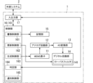
- FIG. 2 is a block diagram of the MEMS sensor diagnostic system according to the embodiment.
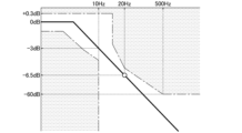
- FIG. 3 is a frequency characteristic diagram of a low-pass filter used in the same MEMS sensor.
- FIG. 4 is a frequency characteristic diagram of a high-pass filter used in the MEMS sensor according to Modification 1 of the embodiment.
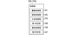
- FIG. 5 is a block diagram of a MEMS sensor diagnostic system according to Modification 2 of the embodiment.
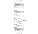
- FIG. 6 is a flowchart of a MEMS sensor diagnosis method according to Modification 2 of the embodiment.
- FIG. 1 An overview of a diagnostic method for the MEMS sensor 1 and a diagnostic system 10 for the MEMS sensor 1 according to the embodiment will be described with reference to FIGS. 1 and 2.
- FIG. 1 An overview of a diagnostic method for the MEMS sensor 1 and a diagnostic system 10 for the MEMS sensor 1 according to the embodiment will be described with reference to FIGS. 1 and 2.
- FIG. 1 An overview of a diagnostic method for the MEMS sensor 1 and a diagnostic system 10 for the MEMS sensor 1 according to the embodiment will be described with reference to FIGS. 1 and 2.
- a diagnostic method for the MEMS sensor 1 is a method for diagnosing the MEMS sensor 1 .
- a MEMS (Micro Electro Mechanical Systems) sensor 1 is, for example, a gyro sensor (angular velocity sensor). In this embodiment, as an example, it is assumed that the MEMS sensor 1 is a uniaxial vibrating gyro sensor.
- the MEMS sensor 1 is not limited to a gyro sensor, and may be an acceleration sensor, for example.
- the MEMS sensor 1 includes an analog circuit section 12 and a digital circuit section 14, as will be described later. At least one of the analog circuit section 12 and the digital circuit section 14 uses a response function. By updating the response coefficient in the response function, the circuit unit outputs a signal corresponding to the updated response coefficient. Therefore, when the response coefficient has not been updated, a signal corresponding to the response coefficient before update is output. Therefore, in the field of MEMS sensor 1, there is a desire for a system capable of confirming whether or not updating of response coefficients was successful.
- the diagnostic method for the MEMS sensor 1 according to the embodiment has the following configuration in order to achieve the above object.
- the diagnostic method for the MEMS sensor 1 is a diagnostic method for the MEMS sensor 1 including the MEMS element 11, the analog circuit section 12, the AD conversion section 13, the digital circuit section 14, and the storage section 15. is.
- the MEMS element 11 outputs a first analog signal corresponding to the magnitude of externally applied stress.
- the analog circuit section 12 performs signal processing on the first analog signal output from the MEMS element 11 and outputs a second analog signal after the signal processing.
- the AD conversion section 13 converts the second analog signal output from the analog circuit section 12 into a digital signal.
- the digital circuit unit 14 generates an output signal corresponding to the magnitude of the stress based on the digital signal output from the AD conversion unit 13 and outputs the output signal to the external system 2 .
- the storage unit 15 stores response coefficients in response functions used in at least one of the analog circuit unit 12 and the digital circuit unit 14 .
- the diagnostic method for the MEMS sensor 1 has, as shown in FIG. 1, a rewrite control step ST1, an update control step ST2, a generation control step ST3, and a determination step ST4.
- the storage unit 15 is caused to execute a rewriting process of rewriting the response coefficient from the first response coefficient to the second response coefficient in accordance with the response coefficient rewriting command from the external system 2 .
- the circuit section is caused to perform update processing for updating the response coefficient from the first response coefficient to the second response coefficient.
- the digital circuit section 14 executes generation processing for generating a digital pseudo-output signal corresponding to the analog pseudo-input signal input to the MEMS element 11 or the analog circuit section 12.
- determination step ST4 determination processing is performed to determine whether or not the pseudo output signal is included within the allowable range defined by the pseudo input signal.
- the pseudo output signal is included within the allowable range defined by the pseudo input signal. Therefore, if the pseudo output signal is within the allowable range, it is determined that the rewriting and updating of the response coefficient are successful, and if the pseudo output signal is not within the allowable range, the rewriting and updating of the response coefficient are determined. can be determined to have failed. That is, according to the diagnostic method for the MEMS sensor 1 according to the embodiment, it is possible to confirm whether or not the rewriting and updating of the response coefficients in the response function used in the MEMS sensor 1 have succeeded.
- the method for diagnosing the MEMS sensor 1 according to the embodiment is realized by, for example, a diagnosis system 10 for the MEMS sensor 1 as shown in FIG. That is, the diagnostic system 10 for the MEMS sensor 1 is one aspect for embodying the diagnostic method for the MEMS sensor 1 described above.
- a diagnostic system 10 for a MEMS sensor 1 according to the embodiment diagnoses a MEMS sensor 1 including a MEMS element 11, an analog circuit section 12, an AD conversion section 13, a digital circuit section 14, and a storage section 15.
- the diagnostic system 10 for the MEMS sensor 1 includes a rewrite controller 161, an update controller 162, a generation controller 163, and a determination unit 164, as shown in FIG.
- the rewriting control unit 161 causes the storage unit 15 to execute a rewriting process of rewriting the response coefficient from the first response coefficient to the second response coefficient in response to the response coefficient rewriting command from the external system 2 .
- the update control section 162 causes the circuit section to perform update processing for updating the response coefficient from the first response coefficient to the second response coefficient.
- the generation control unit 163 generates a digital pseudo output signal according to the analog pseudo input signal input to the MEMS element 11 or the analog circuit unit 12 after the update control unit 162 causes the circuit unit to perform update processing.
- the digital circuit unit 14 is caused to execute the generation processing for
- the determination unit 164 executes determination processing for determining whether or not the pseudo output signal is included within the allowable range defined by the pseudo input signal.
- the MEMS sensor 1 includes a MEMS element 11, an analog circuit section 12, an AD conversion section 13, a digital circuit section 14, a storage section 15, a control section 16, an input and an output unit 17 .
- the control unit 16 of the MEMS sensor 1 functions as the diagnostic system 10 of the MEMS sensor 1 . That is, the diagnostic system 10 for the MEMS sensor 1 according to the embodiment is integrated with the MEMS sensor 1 .
- the later-described rewriting control unit 161 , update control unit 162 , generation control unit 163 and determination unit 164 are integrated with the MEMS sensor 1 .
- the analog circuit section 12, the AD conversion section 13, the digital circuit section 14, the storage section 15, the control section 16, and the input/output section 17 are configured by a single ASIC (Application Specific Integrated Circuit). Note that the analog circuit unit 12, the AD conversion unit 13, the digital circuit unit 14, the storage unit 15, the control unit 16, and the input/output unit 17 are not limited to a single ASIC. It may be composed of a microcomputer.
- the MEMS element 11 is, for example, an angular velocity detection element that detects an angular velocity around the Z-axis among X-axis, Y-axis and Z-axis that are orthogonal to each other.
- the MEMS element 11 has, for example, a vibrator and detection electrodes.
- the vibrator vibrates (displaces), for example, in the X-axis direction.
- the detection electrodes detect the displacement of the vibrator in the Y-axis direction according to the Coriolis force from the electrostatic capacitance generated between them and the vibrator. That is, the MEMS sensor 1 is a capacitive gyro sensor.
- the MEMS element 11 outputs a first analog signal (voltage signal) corresponding to the magnitude of stress applied from the outside. In other words, the MEMS element 11 outputs the first analog signal corresponding to the Coriolis force generated in the MEMS element 11 .
- the configuration of the MEMS element 11 is not limited to the configuration described above, and other configurations may be used as long as the angular velocity around the Z-axis can be detected.
- the MEMS sensor 1 is not limited to the capacitance type, and may be, for example, a piezoelectric type.
- the analog circuit section 12 has its input end connected to the output end of the MEMS element 11 .
- a first analog signal output from the MEMS element 11 is input to the analog circuit section 12 .
- the analog circuit section 12 performs signal processing on the first analog signal from the MEMS element 11 .
- the analog circuit section 12 performs synchronous detection on the first analog signal from the MEMS element 11 and extracts a component signal corresponding to the Coriolis force from the first analog signal.
- the component signal corresponds to the second analog signal. That is, the analog circuit section 12 performs signal processing on the first analog signal output from the MEMS element 11 and outputs the second analog signal after the signal processing.
- the AD (Analog to Digital) conversion section 13 has its input end connected to the output end of the analog circuit section 12 .
- the second analog signal output from the analog circuit section 12 is input to the AD conversion section 13 .
- the AD conversion section 13 converts the second analog signal into a digital signal and outputs the digital signal to the digital circuit section 14 .
- the input terminal of the digital circuit unit 14 is connected to the output terminal of the AD conversion unit 13 .
- a digital signal output from the AD conversion unit 13 is input to the digital circuit unit 14 .
- the digital circuit unit 14 outputs an output signal (angular velocity signal) corresponding to the magnitude of the stress applied to the MEMS element 11 to the external system 2 based on the digital signal output from the AD conversion unit 13 .
- the digital circuit section 14 includes a low-pass filter (LPF: Low Pass Filter) 141, as shown in FIG.
- Low-pass filter 141 is, for example, a digital filter.
- the digital circuit unit 14 uses the low-pass filter 141 to remove or reduce the components of the second frequency band higher than the first frequency band from the digital signal output from the AD conversion unit 13, thereby obtaining the first frequency. Extract the band signal. Further, the digital circuit unit 14 performs gain adjustment and offset adjustment on the extracted signal, further performs compensation processing (for example, temperature compensation processing), and calculates, for example, the average value of angular velocity per unit time. . Then, the digital circuit unit 14 generates an angular velocity signal (output signal) including an average value of angular velocities per unit time, and outputs the signal to the external system 2 .
- LPF Low Pass Filter
- the digital circuit section 14, which is one of the analog circuit section 12 and the digital circuit section 14, has a response function.
- a response function is, for example, a transfer function of the low-pass filter 141 .
- the response coefficient in the response function is the gain of the low-pass filter 141, for example.
- the storage unit 15 includes, for example, non-volatile memory such as flash memory.
- the storage unit 15 stores response coefficients in the response function used in the digital circuit unit 14 . More specifically, the storage unit 15 stores a Look Up Table as shown in Table 1. Table 1 exemplifies a low-pass filter and a high-pass filter as filters used in the digital circuit section 14 .
- controller 16 functions as the diagnostic system 10 for the MEMS sensor 1 according to the embodiment.
- the control unit 16 has a rewrite control unit 161, an update control unit 162, a generation control unit 163, a determination unit 164, and a notification control unit 165, as shown in FIG.
- the diagnostic system 10 for the MENS sensor 1 includes a rewrite control section 161 , an update control section 162 , a generation control section 163 , a determination section 164 and a notification control section 165 .
- the rewrite control unit 161 causes the storage unit 15 to execute rewrite processing in response to a rewrite command from the external system 2 .
- the rewriting process is a process of rewriting the above response coefficient from the first response coefficient to the second response coefficient. That is, in the rewrite process, the storage unit 15 rewrites the above response coefficient from the first response coefficient to the second response coefficient according to the control command from the rewrite control unit 161 .
- the update control unit 162 causes at least one of the analog circuit unit 12 and the digital circuit unit 14 to perform update processing.
- the update process is a process of updating the above response coefficient from the first response coefficient to the second response coefficient. That is, the circuit unit updates the above response coefficient from the first response coefficient to the second response coefficient in accordance with the control command from the update control unit 162 .
- the circuit section is the digital circuit section 14 .
- the generation control unit 163 causes the digital circuit unit 14 to execute the generation process after the update control unit 162 causes the digital circuit unit 14 to execute the update process.
- the generation process is a process of generating a pseudo output signal according to the pseudo input signal input to the MEMS element 11 .
- the pseudo input signal is a signal input to the MEMS element 11 and is an analog signal. More specifically, the pseudo input signal is an alternating signal (AC signal) corresponding to the magnitude of pseudo stress applied to the MEMS element 11 .
- the pseudo output signal is a digital signal output from the digital circuit section 14 .
- the determination unit 164 executes determination processing.
- the determination process is a process of determining whether or not the pseudo output signal is within the allowable range.
- the allowable range of the pseudo output signal is defined by the pseudo input signal. Further, in the determination processing, the determining unit 164 determines that the rewriting and updating of the response coefficient are successful when the pseudo output signal is within the allowable range, and the pseudo output signal is not within the allowable range. If so, it is determined that rewriting and updating of the response coefficient have failed.
- the notification control unit 165 causes the external system 2 to perform notification processing when the determination unit 164 determines that the pseudo output signal is not within the allowable range.
- the notification process is a process for notifying that an error has occurred in a rewrite control step ST1 or an update control step ST2, which will be described later. That is, the external system 2 notifies that an error has occurred in the rewrite control step ST1 or the update control step ST2 according to the control command from the notification control unit 165.
- FIG. As for the method of notification, for example, if the external system 2 has a display unit, the content of the notification may be displayed on the display unit, or if the external system 2 has a speaker, the content of the notification may be notified by voice. You may This allows the user of the MEMS sensor 1 to know that an error has occurred in the rewrite control step ST1 or the update control step ST2 and that the rewrite or update of the response coefficient has failed.
- the input/output unit 17 includes an input/output interface with the external system 2 .
- the input/output unit 17 inputs a rewrite command or the like from the external system 2 to the control unit 16 (diagnostic system 10).
- the input/output unit 17 also outputs an output signal (angular velocity signal) from the digital circuit unit 14 , the determination result of the determination unit 164 , a control command from the notification control unit 165 , and the like to the external system 2 .
- a method for diagnosing the MEMS sensor 1 is a method for diagnosing the MEMS sensor 1 including the MEMS element 11, the analog circuit section 12, the AD conversion section 13, the digital circuit section 14, and the storage section 15. .
- the MEMS element 11 outputs a first analog signal corresponding to the magnitude of externally applied stress.
- the analog circuit section 12 performs signal processing on the first analog signal output from the MEMS element 11 and outputs a second analog signal after the signal processing.
- the AD conversion section 13 converts the second analog signal output from the analog circuit section 12 into a digital signal.
- the digital circuit unit 14 generates an output signal corresponding to the magnitude of the stress based on the digital signal output from the AD conversion unit 13 and outputs the output signal to the external system 2 .
- the storage unit 15 stores response coefficients in the response function used in at least one of the analog circuit unit 12 and the digital circuit unit 14 .
- the diagnostic method for the MEMS sensor 1 has a rewrite control step ST1, an update control step ST2, a generation control step ST3, and a determination step ST4.
- the storage unit 15 is caused to execute a rewrite process of rewriting the response coefficient from the first response coefficient to the second response coefficient in accordance with the response coefficient rewrite command from the external system 2 .
- the circuit section (the digital circuit section 14 in this embodiment) is caused to execute update processing for updating the response coefficient from the first response coefficient to the second response coefficient.
- the digital circuit section 14 is caused to perform a generation process of generating a pseudo output signal according to the pseudo input signal input to the MEMS element 11 or the analog circuit section 12.
- determination step ST4 determination processing is performed to determine whether or not the pseudo output signal falls within the allowable range defined by the pseudo input signal.
- step ST4 it is determined whether or not the pseudo output signal falls within the allowable range defined by the pseudo input signal. Therefore, if the pseudo output signal is within the allowable range, it is determined that the rewriting and updating of the response coefficient are successful, and if the pseudo output signal is not within the allowable range, it is determined that the rewriting or updating of the response coefficient has failed. It becomes possible to That is, according to the diagnostic method for the MEMS sensor 1 according to the embodiment, it is possible to confirm whether or not the rewriting and updating of the response coefficients in the response function used in the MEMS sensor 1 have succeeded.
- the diagnostic method for the MEMS sensor 1 further includes a notification control step ST5.
- the notification control step ST5 if it is determined in the determination step ST4 that the pseudo output signal is not within the allowable range, the notification processing for notifying that an error has occurred in the rewrite control step ST1 or the update control step ST2 is performed externally. Let System 2 execute. This makes it possible to inform the user of the MEMS sensor 1 that an error has occurred in the rewrite control step ST1 or the update control step ST2 and that rewriting or updating of the response coefficient has failed.
- FIG. 1 is a flowchart of a diagnostic method for the MEMS sensor 1 according to the embodiment.
- the diagnostic method for the MEMS sensor 1 has steps ST1 to ST5 shown in FIG. Note that the flowchart shown in FIG. 1 is an example, and the order of each step may be changed as appropriate, or one of the steps may be omitted.
- the diagnostic system 10 of the MEMS sensor 1 executes the rewriting control step ST1.
- the rewrite control unit 161 performs a rewrite process of rewriting the response coefficients stored in the storage unit 15 from the first response coefficients to the second response coefficients in response to a rewrite command from the external system 2. 15 to execute. That is, the storage unit 15 rewrites the response coefficient from the first response coefficient to the second response coefficient according to the control command from the rewrite control unit 161 .
- the diagnostic system 10 for the MEMS sensor 1 executes an update control step ST2.
- the update control unit 162 instructs the circuit unit to update the response coefficient in the response function used in the circuit unit (here, the digital circuit unit 14) from the first response coefficient to the second response coefficient. let it run. That is, the circuit unit updates the response coefficient from the first response coefficient to the second response coefficient according to the control command from the update control unit 162 .
- the diagnostic system 10 for the MEMS sensor 1 executes the generation control step ST3 after the update control step ST2.
- the generation control section 163 inputs a pseudo input signal made up of an analog signal to the MEMS sensor 1 and causes the digital circuit section 14 to generate a pseudo output signal made up of a digital signal. That is, in the generation process, the digital circuit section 14 generates a pseudo output signal according to the pseudo input signal input from the generation control section 163 to the MEMS sensor 1 .
- the diagnostic system 10 for the MEMS sensor 1 executes determination step ST4.
- the determination section 164 executes determination processing for determining whether or not the pseudo output signal from the digital circuit section 14 is within the allowable range. Then, the determining unit 164 determines that the rewriting and updating of the response coefficient are successful when the pseudo output signal is within the allowable range, and determines that the response coefficient is successfully updated when the pseudo output signal is not within the allowable range. It is determined that the rewriting or updating of has failed.
- the diagnosis system 10 of the MEMS sensor 1 executes notification control step ST5 when it is determined in determination step ST4 that the pseudo output signal is not within the allowable range.
- the notification control unit 165 executes notification processing to notify the external system 2 that an error has occurred in the rewrite control step ST1 or the update control step ST2, that is, that the rewriting or updating of the response coefficient has failed. Let That is, the external system 2 executes the notification process described above in accordance with the control command from the notification control unit 165 .
- the rewrite control step ST1, the update control step ST2, the generation control step ST3, and the determination step ST4 are executed.
- the MEMS sensor 1 is activated, external stress is not applied to the MEMS sensor 1, and it is possible to suppress erroneous diagnosis due to actual stress on the MEMS sensor 1.
- FIG. 3 is a frequency characteristic diagram of the low-pass filter 141 included in the digital circuit section 14. As shown in FIG. The horizontal axis in FIG. 3 is frequency, and the vertical axis in FIG. 3 is gain. Also, in FIG. 3, the cut frequency of the low-pass filter 141 is 10 Hz. Also, in FIG. 3, the portion excluding the allowable range of the pseudo output signal defined by the pseudo input signal is indicated by dot hatching. That is, the allowable range is the portion not marked with dot hatching in FIG.
- the determination unit 164 acquires the frequency characteristic of the low-pass filter 141 by performing processing such as Fourier transform on the pseudo output signal output from the digital circuit unit 14 (see FIG. 3).
- the gain of the low-pass filter 141 is contained within the allowable range. For example, when the frequency of the pseudo output signal is 20 Hz, the gain of low-pass filter 141 is -6.5 dB.
- the lookup table (see Table 1) stored in the storage unit 15, for the low-pass filter 141 whose cutoff frequency is 10 Hz, the gain when the frequency of the pseudo output signal is 20 Hz is -6. 5 dB.
- the determining unit 164 determines that the rewriting and updating of the response coefficient (gain) of the low-pass filter 141 have succeeded. Further, when the two results do not match, the determination unit 164 determines that rewriting or updating of the response coefficient of the low-pass filter 141 has failed.
- “A and B match” includes not only the case where A and B are exactly the same, but also the case where B is included in a predetermined range including A.
- the diagnostic method for the MEMS sensor 1 further includes a notification control step ST5. Therefore, it is possible for the external system 2 to notify that an error has occurred in the rewrite control step ST1 or the update control step ST2.
- the rewrite control step ST1, the update control step ST2, the generation control step ST3, and the determination step ST4 are executed. Therefore, it is possible to suppress erroneous diagnosis due to actual stress applied to the MEMS sensor 1 from the outside.
- the pseudo input signal is an AC signal corresponding to the magnitude of the pseudo stress on the MEMS element 11 . Therefore, simply by inputting an AC signal to the MEMS element 11 or the analog circuit section 12, it is possible to confirm whether or not the rewriting and updating of the response coefficients in the response function used in the MEMS sensor 1 have succeeded. Become.
- the above-described embodiment is just one of various embodiments of the present disclosure.
- the above-described embodiments can be modified in various ways according to design and the like as long as the object of the present disclosure can be achieved.
- the same function as the diagnostic method for the MEMS sensor 1 according to the above-described embodiment may be embodied by the diagnostic system 10 for the MEMS sensor 1, a (computer) program, or a non-temporary recording medium recording the program. good.
- the diagnostic system for the MEMS sensor 1 according to Modification 1 differs from the diagnostic system 10 for the MEMS sensor 1 according to the above-described embodiment in that the filter used in the digital circuit section 14 is a high-pass filter.
- a diagnostic system for the MEMS sensor 1 and a diagnostic method for the MEMS sensor 1 according to Modification 1 will be described below with reference to FIG.
- the diagnostic system for the MEMS sensor 1 according to Modification 1 the same components as those of the diagnostic system 10 for the MEMS sensor 1 according to the above-described embodiment are denoted by the same reference numerals, and description thereof is omitted.
- the diagnostic method for the MEMS sensor 1 according to Modification 1 the same components as those in the diagnostic method for the MEMS sensor 1 according to the above-described embodiment are denoted by the same reference numerals, and descriptions thereof are omitted.
- the diagnosis system for the MEMS sensor 1 executes the rewrite control step ST1, the update control step ST2, the generation control step ST3, the determination step ST4, and the notification control step ST5 in this order.
- the diagnostic system for the MEMS sensor 1 determines whether or not the pseudo output signal from the digital circuit section 14 is within the allowable range in determination step ST4.
- FIG. 4 is a frequency characteristic diagram of the high-pass filter used in the digital circuit section 14.
- FIG. The horizontal axis of FIG. 4 is frequency, and the vertical axis of FIG. 4 is gain.
- the cut frequency of the high-pass filter is 10 Hz.
- the portion excluding the allowable range defined by the pseudo input signal is indicated by dot hatching. That is, the allowable range is the portion not marked with dot hatching in FIG.
- the determination unit 164 acquires the frequency characteristic of the high-pass filter by performing processing such as Fourier transform on the pseudo output signal output from the digital circuit unit 14 (see FIG. 4).
- the gain of the high-pass filter is contained within the allowable range. For example, if the frequency of the simulated output signal is 20 Hz, the gain of the high pass filter is 0 dB.
- the lookup table (see Table 1) stored in the storage unit 15, the gain of the high-pass filter whose cutoff frequency is 10 Hz is 0 dB when the frequency of the pseudo output signal is 20 Hz.
- the determining unit 164 determines that the rewriting and updating of the response coefficient (gain) of the high-pass filter have succeeded. Further, when the two results do not match, the determination unit 164 determines that rewriting or updating of the response coefficient of the high-pass filter has failed.
- the method for diagnosing the MEMS sensor 1 according to Modification 2 differs from the method for diagnosing the MEMS sensor 1 according to the above-described embodiment in that it has two determination steps (a first determination step ST14 and a second determination step ST16). .
- a diagnostic method for the MEMS sensor 1 and a diagnostic system 10A for the MEMS sensor 1 according to Modification 2 will be described below with reference to FIGS. 5 and 6.
- FIG. Regarding the diagnosis system 10A for the MEMS sensor 1 according to Modification 2 the same components as those of the diagnosis system 10 for the MEMS sensor 1 according to the above-described embodiment are denoted by the same reference numerals, and descriptions thereof are omitted.
- a diagnosis system 10A for the MEMS sensor 1 according to Modification 2 includes a rewrite control unit 161, an update control unit 162, a generation control unit 163, a notification control unit 165, and a first determination unit 166. , and a second determination unit 167 .
- the first determination unit 166 corresponds to the determination unit 164 of the diagnostic system 10 for the MEMS sensor 1 according to the embodiment described above. That is, the first determination unit 166 determines whether or not the digital pseudo output signal from the digital circuit unit 14 (see FIG. 2) is within the allowable range defined by the analog pseudo input signal. 1 judgment processing is executed.
- the generation control unit 163 When the rewrite control unit 161 causes the storage unit 15 to execute rewrite processing once and the update control unit 162 causes the circuit unit (here, the digital circuit unit 14) to execute update processing once, the generation control unit 163 , outputs a plurality of (for example, three) pseudo input signals to the MEMS sensor 1 .
- the first determination section 166 executes a first determination process for each of the plurality of pseudo output signals output from the digital circuit section 14 (see FIG. 2) with respect to the plurality of pseudo input signals. That is, the first determination unit 166 performs the first determination process when the rewrite control unit 161 causes the storage unit 15 to execute the rewriting process once and the update control unit 162 causes the circuit unit to execute the update process once. It is executed multiple times (here, three times).
- the second determination unit 167 executes the second determination process based on the determination result of the first determination unit 166.
- the second determination process is a process of determining whether or not the number of times the pseudo output signal is included in the allowable range is equal to or greater than a specified number of times.
- the second determination unit 167 determines that the rewriting and updating of the response coefficient are successful when the number of times the pseudo output signal is included in the allowable range is equal to or greater than the specified number of times, and , it is determined that rewriting or updating of the response coefficient has failed.
- the specified number of times is, for example, two. That is, the second determination unit 167 determines that the rewriting and updating of the response coefficient have succeeded when the ratio of the specified number of times to the number of executions of the first determination process is equal to or greater than a predetermined value (eg, 60%).
- a diagnostic method for the MEMS sensor 1 according to Modification 2 includes, as shown in FIG. and a notification control step ST17.
- the rewrite control step ST11 corresponds to the rewrite control step ST1 described above
- the update control step ST12 corresponds to the update control step ST2 described above.
- the generation control step ST13 corresponds to the generation control step ST3 described above
- the notification control step ST17 corresponds to the notification control step ST5 described above.
- the diagnostic system 10A for the MEMS sensor 1 executes the rewrite control step ST11.
- the rewrite control unit 161 performs rewrite processing to rewrite the response coefficients stored in the storage unit 15 from the first response coefficients to the second response coefficients in accordance with the rewrite command from the external system 2. 15 to execute.
- the storage unit 15 rewrites the response coefficient from the first response coefficient to the second response coefficient according to the control command from the rewrite control unit 161 .
- the diagnostic system 10A for the MEMS sensor 1 executes an update control step ST12.
- the update control unit 162 causes the digital circuit unit 14 to perform update processing for updating the response coefficients used in the circuit unit (here, the digital circuit unit 14) from the first response coefficients to the second response coefficients.
- the digital circuit unit 14 updates the response coefficient from the first response coefficient to the second response coefficient according to the control command from the update control unit 162 .
- the diagnosis system 10A for the MEMS sensor 1 executes the generation control step ST13 after the update control step ST12.
- the generation control section 163 inputs an analog pseudo input signal to the MEMS sensor 1 and causes the digital circuit section 14 to generate a digital pseudo output signal corresponding to this pseudo input signal.
- the digital circuit unit 14 generates a digital pseudo output signal corresponding to the analog pseudo input signal input to the MEMS sensor 1 in accordance with the control command from the generation control unit 163 .
- the diagnostic system 10A for the MEMS sensor 1 executes the first determination step ST14.
- the first determination section 166 performs a first determination process of determining whether or not the pseudo output signal from the digital circuit section 14 is within the allowable range defined by the pseudo input signal. Execute.
- the diagnosis system 10A for the MEMS sensor 1 determines whether or not the first determination step ST14 has been executed a predetermined number of times (eg, three times) (step ST15).
- the diagnosis system 10A for the MEMS sensor 1 returns to the generation control step ST13 if the number of executions of the first determination step ST14 is not the predetermined number (step ST15: No).
- the diagnosis system 10A for the MEMS sensor 1 repeats the generation control step ST13 and the first determination step ST14 until the number of executions of the first determination step ST14 reaches a predetermined number.
- the diagnostic system 10A for the MEMS sensor 1 proceeds to the second determination step ST16 when the number of times of execution of the first determination step ST14 reaches a predetermined number (step ST15: Yes).
- the diagnostic system 10A for the MEMS sensor 1 executes a second determination step ST16.
- the second determination section 167 executes a second determination process of determining whether or not the number of times the pseudo output signal is included in the allowable range is equal to or greater than a specified number of times. In the second determination process, if the number of times the pseudo output signal is included in the allowable range is equal to or greater than the specified number of times, the second determination unit 167 determines that the rewrite control step ST11 and the update control step ST12 are successful, that is, the response coefficient is increased. It is determined that the rewrite and update were successful.
- the second determination unit 167 determines that an error has occurred in the rewrite control step ST11 or the update control step ST12. , that is, it is determined that rewriting or updating of the response coefficient has failed.
- the diagnostic system 10A of the MEMS sensor 1 executes the notification control step ST17 when an error occurs in the rewrite control step ST11 or the update control step ST12 from the determination result of the second determination unit 167.
- the notification control unit 165 outputs a control command to the external system 2 to notify that an error has occurred in the rewrite control step ST11 or the update control step ST12, that is, the rewrite or update of the response coefficient has failed.
- the external system 2 notifies that it has been done.
- the generation control step ST13 and the first determination step ST14 are executed multiple times. Then, in the diagnostic method for the MEMS sensor 1, when the number of times the pseudo output signal is included in the allowable range is equal to or greater than a specified number of times, the second determination step ST16 is performed to determine that the rewriting and updating of the response coefficient have succeeded. Execute. This makes it possible to confirm whether or not the rewriting and updating of the response coefficients in the response function used in the MEMS sensor 1 have succeeded.
- the executing subject of the diagnostic system 10 for the MEMS sensor 1 or the diagnostic method for the MEMS sensor 1 in the present disclosure includes a computer system.
- a computer system is mainly composed of a processor and a memory as hardware.
- the processor executes a program recorded in the memory of the computer system, thereby realizing a function as an executing subject of the diagnostic system 10 for the MEMS sensor 1 or the diagnostic method for the MEMS sensor 1 in the present disclosure.
- the program may be recorded in advance in the memory of the computer system, may be provided through an electric communication line, or may be recorded in a non-temporary recording medium such as a computer system-readable memory card, optical disk, or hard disk drive. may be provided.
- a processor in a computer system is made up of one or more electronic circuits, including semiconductor integrated circuits (ICs) or large scale integrated circuits (LSIs).
- Integrated circuits such as ICs or LSIs are called differently depending on the degree of integration, and include integrated circuits called system LSI, VLSI (Very Large Scale Integration), or ULSI (Ultra Large Scale Integration).
- FPGAs Field-Programmable Gate Arrays
- logic devices capable of reconfiguring the connection relationships inside the LSI or reconfiguring the circuit partitions inside the LSI shall also be adopted as processors. can be done.
- a plurality of electronic circuits may be integrated into one chip, or may be distributed over a plurality of chips.
- a plurality of chips may be integrated in one device, or may be distributed in a plurality of devices.
- a computer system includes a microcontroller having one or more processors and one or more memories. Accordingly, the microcontroller also consists of one or more electronic circuits including semiconductor integrated circuits or large scale integrated circuits.
- the diagnostic system 10 of the MEMS sensor 1 it is not an essential configuration of the diagnostic system 10 of the MEMS sensor 1 that a plurality of functions in the diagnostic system 10 of the MEMS sensor 1 are integrated in one housing, but it is a component of the diagnostic system 10 of the MEMS sensor 1. may be distributed over a plurality of housings. Furthermore, at least part of the functions of the diagnostic system 10 for the MEMS sensor 1, for example, the functions of the determination unit 164, may be realized by the cloud (cloud computing) or the like.
- the pseudo input signal is input to the MEMS element 11 in the above embodiment, the pseudo input signal may be input to the analog circuit section 12, for example.
- the processing time for the MEMS element 11 can be omitted, and the processing time for the entire MEMS sensor 1 can be shortened.
- the responsiveness of the MEMS element 11 is not good, it is necessary to input a pseudo input signal to the MEMS element 11 .
- the MEMS sensor 1 and the diagnosis system 10 for the MEMS sensor 1 are integrated. It may be separate from one diagnostic system 10 . Further, in the above-described embodiment, the entire diagnostic system 10 for the MEMS sensor 1 and the MEMS sensor 1 are integrated. 1 may be integrated.
- the rewrite control step ST1, the update control step ST2, the generation control step ST3, and the determination step ST4 are executed.
- the rewrite control step ST1, the update control step ST2, the generation control step ST3, and the determination step ST4 may be executed in response to a request from the external system 2.
- diagnosis can be performed at the timing of the user of the MEMS sensor 1 .
- the analog circuit section 12 may include the low-pass filter, or both the analog circuit section 12 and the digital circuit section 14 may include the low-pass filter. may contain. In short, at least one of the analog circuit section 12 and the digital circuit section 14 includes a low-pass filter.
- a diagnostic method for a MENS sensor (1) includes a MEMS element (11), an analog circuit section (12), an AD conversion section (13), a digital circuit section (14), a storage section ( 15), and a method for diagnosing a MEMS sensor (1).
- the MEMS element (11) outputs a first analog signal corresponding to the magnitude of externally applied stress.
- An analog circuit section (12) performs signal processing on the first analog signal output from the MEMS element (11) and outputs a second analog signal after the signal processing.
- An AD conversion section (13) converts the second analog signal output from the analog circuit section (12) into a digital signal.
- a digital circuit unit (14) generates an output signal corresponding to the magnitude of the stress based on the digital signal output from the AD conversion unit (13), and outputs the output signal to the external system (2).
- a storage unit (15) stores a response coefficient in a response function used in at least one of the analog circuit unit (12) and the digital circuit unit (14).
- a diagnostic method for the MEMS sensor (1) includes a rewrite control step (ST1; ST11), an update control step (ST2; ST12), a generation control step (ST3; ST13), and a determination step (ST4; ST14). have.
- a rewrite process for rewriting the response coefficient from the first response coefficient to the second response coefficient is stored in the storage unit (15) in response to a response coefficient rewrite command from the external system (2). let it run.
- the update control step (ST2; ST12) the circuit section is caused to perform update processing for updating the response coefficient from the first response coefficient to the second response coefficient.
- the generation control step (ST3; ST13) after the update control step (ST2; ST12), a digital pseudo output signal corresponding to the analog pseudo input signal input to the MEMS element (11) or the analog circuit section (12). is executed by the digital circuit unit (14).
- determination processing is performed to determine whether or not the pseudo output signal is included within the allowable range defined by the pseudo input signal.
- the diagnostic method for the MEMS sensor (1) according to the second aspect further includes a notification control step (ST5) in the first aspect.
- a notification control step (ST5) if it is determined in the determination step (ST4) that the pseudo output signal is not within the allowable range, an error occurs in the rewrite control step (ST1) or the update control step (ST2). It causes the external system (2) to execute a notification process for notifying that.
- the external system (2) it is possible for the external system (2) to notify that an error has occurred in the rewrite control step (ST1) or the update control step (ST2).
- the rewriting control step ( ST1), update control step (ST2), generation control step (ST3) and determination step (ST4) are executed.
- diagnosis can be performed at the timing of the user of the MEMS sensor (1).
- the diagnostic method for the MEMS sensor (1) when executing the rewrite control step (ST11) and the update control step (ST12) once , the generation control step (ST13) and the first determination step (ST14), which are the determination step (ST14), are executed multiple times.
- the diagnostic method for the MEMS sensor (1) further comprises a second determination step (ST16). In the second determination step (ST16), if the number of times the pseudo output signal is included in the allowable range is equal to or greater than a specified number of times, it is determined that the rewriting and updating of the response coefficients have succeeded.
- a method for diagnosing a MEMS sensor (1) according to a fifth aspect is such that, in the first to fourth aspects, the pseudo input signal is an AC signal corresponding to the magnitude of the pseudo stress on the MEMS element (11). .
- the circuit section (14) includes a low-pass filter (141).
- the circuit section (14) can extract a digital signal in a desired frequency band.
- a diagnostic system (10) for a MEMS sensor (1) comprises a MEMS element (11), an analog circuit section (12), an AD conversion section (13), a digital circuit section (14), A diagnostic system (10) for a MEMS sensor (1) for diagnosing the MEMS sensor (1), comprising a memory (15).
- the MEMS element (11) outputs a first analog signal corresponding to the magnitude of externally applied stress.
- An analog circuit section (12) performs signal processing on the first analog signal output from the MEMS element (11) and outputs a second analog signal after the signal processing.
- An AD conversion section (13) converts the second analog signal output from the analog circuit section (12) into a digital signal.
- a digital circuit unit (14) generates an output signal corresponding to the magnitude of the stress based on the digital signal output from the AD conversion unit (13), and outputs the output signal to the external system (2).
- a storage unit (15) stores a response coefficient in a response function used in at least one of the analog circuit unit (12) and the digital circuit unit (14).
- a diagnostic system (10) for a MEMS sensor (1) comprises a rewrite control section (161), an update control section (162), a generation control section (163), and a determination section (164).
- a rewriting control unit (161) executes a rewriting process for rewriting the response coefficient from the first response coefficient to the second response coefficient in the storage unit (15) in response to the response coefficient rewriting command from the external system (2).
- the update control section (162) causes the circuit section (14) to perform update processing for updating the response coefficient from the first response coefficient to the second response coefficient.
- a generation control unit (163) receives an analog pseudo input input to the MEMS element (11) or the analog circuit unit (12) after the update control unit (162) causes the circuit unit (14) to perform the update process.
- a digital circuit unit (14) is caused to perform a generation process for generating a digital pseudo output signal corresponding to the signal.
- a judging section (164) executes a judging process for judging whether or not the pseudo output signal is included in the allowable range defined by the pseudo input signal.
- the rewrite control unit (161), the update control unit (162), the generation control unit (163) and the determination unit (164) ) is integral with the MEMS sensor (1).
- the size of the entire system can be reduced.
- the configurations according to the second to sixth aspects are not essential configurations for the diagnostic method of the MEMS sensor (1), and can be omitted as appropriate.
- the configuration according to the eighth aspect is not an essential configuration for the diagnostic system (10; 10A) of the MEMS sensor (1), and can be omitted as appropriate.
Landscapes
- Engineering & Computer Science (AREA)
- Physics & Mathematics (AREA)
- General Physics & Mathematics (AREA)
- Radar, Positioning & Navigation (AREA)
- Remote Sensing (AREA)
- Manufacturing & Machinery (AREA)
- Signal Processing (AREA)
- Testing Or Calibration Of Command Recording Devices (AREA)
- Measuring Fluid Pressure (AREA)
Priority Applications (3)
| Application Number | Priority Date | Filing Date | Title |
|---|---|---|---|
| JP2023578436A JPWO2023149172A1 (cg-RX-API-DMAC7.html) | 2022-02-02 | 2023-01-13 | |
| CN202380018544.8A CN118613729A (zh) | 2022-02-02 | 2023-01-13 | Mems传感器的诊断方法及诊断系统 |
| US18/835,190 US20250180374A1 (en) | 2022-02-02 | 2023-01-13 | Diagnostic method and diagnostic system of mems sensor |
Applications Claiming Priority (2)
| Application Number | Priority Date | Filing Date | Title |
|---|---|---|---|
| JP2022-015215 | 2022-02-02 | ||
| JP2022015215 | 2022-02-02 |
Publications (1)
| Publication Number | Publication Date |
|---|---|
| WO2023149172A1 true WO2023149172A1 (ja) | 2023-08-10 |
Family
ID=87551989
Family Applications (1)
| Application Number | Title | Priority Date | Filing Date |
|---|---|---|---|
| PCT/JP2023/000882 Ceased WO2023149172A1 (ja) | 2022-02-02 | 2023-01-13 | Memsセンサの診断方法及びmemsセンサの診断システム |
Country Status (4)
| Country | Link |
|---|---|
| US (1) | US20250180374A1 (cg-RX-API-DMAC7.html) |
| JP (1) | JPWO2023149172A1 (cg-RX-API-DMAC7.html) |
| CN (1) | CN118613729A (cg-RX-API-DMAC7.html) |
| WO (1) | WO2023149172A1 (cg-RX-API-DMAC7.html) |
Families Citing this family (1)
| Publication number | Priority date | Publication date | Assignee | Title |
|---|---|---|---|---|
| US20250020465A1 (en) * | 2022-02-02 | 2025-01-16 | Panasonic Intellectual Property Management Co., Ltd. | Gyro sensor |
Citations (4)
| Publication number | Priority date | Publication date | Assignee | Title |
|---|---|---|---|---|
| US20070169551A1 (en) * | 2005-06-13 | 2007-07-26 | Analog Devices, Inc. | MEMS Sensor System with Configurable Signal Module |
| JP2009063471A (ja) * | 2007-09-07 | 2009-03-26 | Denso Corp | センサ装置 |
| JP2010043962A (ja) * | 2008-08-13 | 2010-02-25 | Epson Toyocom Corp | 角速度検出回路、角速度検出装置及び角速度検出装置の故障診断方法 |
| JP2018100939A (ja) * | 2016-12-21 | 2018-06-28 | 株式会社デンソー | 衝突検知センサ |
-
2023
- 2023-01-13 JP JP2023578436A patent/JPWO2023149172A1/ja not_active Withdrawn
- 2023-01-13 CN CN202380018544.8A patent/CN118613729A/zh not_active Withdrawn
- 2023-01-13 US US18/835,190 patent/US20250180374A1/en active Pending
- 2023-01-13 WO PCT/JP2023/000882 patent/WO2023149172A1/ja not_active Ceased
Patent Citations (4)
| Publication number | Priority date | Publication date | Assignee | Title |
|---|---|---|---|---|
| US20070169551A1 (en) * | 2005-06-13 | 2007-07-26 | Analog Devices, Inc. | MEMS Sensor System with Configurable Signal Module |
| JP2009063471A (ja) * | 2007-09-07 | 2009-03-26 | Denso Corp | センサ装置 |
| JP2010043962A (ja) * | 2008-08-13 | 2010-02-25 | Epson Toyocom Corp | 角速度検出回路、角速度検出装置及び角速度検出装置の故障診断方法 |
| JP2018100939A (ja) * | 2016-12-21 | 2018-06-28 | 株式会社デンソー | 衝突検知センサ |
Also Published As
| Publication number | Publication date |
|---|---|
| US20250180374A1 (en) | 2025-06-05 |
| JPWO2023149172A1 (cg-RX-API-DMAC7.html) | 2023-08-10 |
| CN118613729A (zh) | 2024-09-06 |
Similar Documents
| Publication | Publication Date | Title |
|---|---|---|
| US10445285B2 (en) | Integrated data concentrator for multi-sensor MEMS systems | |
| CN108369246A (zh) | Mems加速度计误差的识别和补偿 | |
| CN112118515B (zh) | 定向声学传感器、以及调整定向特性的方法 | |
| JP7361317B2 (ja) | 信号処理装置、慣性力センサ、信号処理方法、及びプログラム | |
| CN113507662B (zh) | 降噪处理方法、装置、设备、存储介质及程序 | |
| JP2011203028A (ja) | 角速度および加速度の検出装置 | |
| CN115808172A (zh) | 惯性传感器模块 | |
| JPH11211481A (ja) | 姿勢角度検出装置 | |
| JP2015184157A (ja) | 物理量検出回路、物理量検出装置、電子機器及び移動体 | |
| CN103787266B (zh) | 机械部件、机械系统和用于运行机械部件的方法 | |
| JP5444875B2 (ja) | ロボット制御装置 | |
| WO2006121583A1 (en) | Improvement of environmental characteristic determination | |
| CN118613729A (zh) | Mems传感器的诊断方法及诊断系统 | |
| WO2020200132A1 (zh) | 麦克风阵列的电子装置及其应用方法 | |
| CN106258000B (zh) | 加速度检测器和有源噪声控制装置 | |
| JPWO2010092806A1 (ja) | 慣性力センサとそれに用いる検出素子 | |
| JP2023140589A (ja) | 物理量検出回路及び物理量検出装置 | |
| CN114323012A (zh) | 双mems惯性测量单元的数据处理方法及双mems惯性测量装置 | |
| CN120303539A (zh) | 设备状态监视系统 | |
| CN106170681A (zh) | 自适应声学强度分析仪 | |
| WO2021245993A1 (ja) | 慣性力検出回路、慣性力センサ及び慣性力検出方法 | |
| JP7394352B2 (ja) | 信号処理装置、慣性力センサ、信号処理方法、及びプログラム | |
| JPS60233563A (ja) | 加速度計測装置 | |
| CN113126791B (zh) | 一种时间戳记录设备、系统、方法、介质及装置 | |
| US20250358568A1 (en) | Noise control method and apparatus, chip, and vehicle |
Legal Events
| Date | Code | Title | Description |
|---|---|---|---|
| 121 | Ep: the epo has been informed by wipo that ep was designated in this application |
Ref document number: 23749489 Country of ref document: EP Kind code of ref document: A1 |
|
| ENP | Entry into the national phase |
Ref document number: 2023578436 Country of ref document: JP Kind code of ref document: A |
|
| WWE | Wipo information: entry into national phase |
Ref document number: 202380018544.8 Country of ref document: CN |
|
| WWE | Wipo information: entry into national phase |
Ref document number: 18835190 Country of ref document: US |
|
| NENP | Non-entry into the national phase |
Ref country code: DE |
|
| 122 | Ep: pct application non-entry in european phase |
Ref document number: 23749489 Country of ref document: EP Kind code of ref document: A1 |
|
| WWP | Wipo information: published in national office |
Ref document number: 18835190 Country of ref document: US |