WO2023149161A1 - 情報処理装置、推論装置、機械学習装置、情報処理方法、推論方法、及び、機械学習方法 - Google Patents
情報処理装置、推論装置、機械学習装置、情報処理方法、推論方法、及び、機械学習方法 Download PDFInfo
- Publication number
- WO2023149161A1 WO2023149161A1 PCT/JP2023/000371 JP2023000371W WO2023149161A1 WO 2023149161 A1 WO2023149161 A1 WO 2023149161A1 JP 2023000371 W JP2023000371 W JP 2023000371W WO 2023149161 A1 WO2023149161 A1 WO 2023149161A1
- Authority
- WO
- WIPO (PCT)
- Prior art keywords
- substrate
- information
- substrate holding
- holding mechanism
- state information
- Prior art date
- Legal status (The legal status is an assumption and is not a legal conclusion. Google has not performed a legal analysis and makes no representation as to the accuracy of the status listed.)
- Ceased
Links
Images







Classifications
-
- H—ELECTRICITY
- H10—SEMICONDUCTOR DEVICES; ELECTRIC SOLID-STATE DEVICES NOT OTHERWISE PROVIDED FOR
- H10P—GENERIC PROCESSES OR APPARATUS FOR THE MANUFACTURE OR TREATMENT OF DEVICES COVERED BY CLASS H10
- H10P52/00—Grinding, lapping or polishing of wafers, substrates or parts of devices
-
- B—PERFORMING OPERATIONS; TRANSPORTING
- B24—GRINDING; POLISHING
- B24B—MACHINES, DEVICES, OR PROCESSES FOR GRINDING OR POLISHING; DRESSING OR CONDITIONING OF ABRADING SURFACES; FEEDING OF GRINDING, POLISHING, OR LAPPING AGENTS
- B24B37/00—Lapping machines or devices; Accessories
- B24B37/005—Control means for lapping machines or devices
-
- B—PERFORMING OPERATIONS; TRANSPORTING
- B24—GRINDING; POLISHING
- B24B—MACHINES, DEVICES, OR PROCESSES FOR GRINDING OR POLISHING; DRESSING OR CONDITIONING OF ABRADING SURFACES; FEEDING OF GRINDING, POLISHING, OR LAPPING AGENTS
- B24B37/00—Lapping machines or devices; Accessories
- B24B37/27—Work carriers
- B24B37/30—Work carriers for single side lapping of plane surfaces
-
- B—PERFORMING OPERATIONS; TRANSPORTING
- B24—GRINDING; POLISHING
- B24B—MACHINES, DEVICES, OR PROCESSES FOR GRINDING OR POLISHING; DRESSING OR CONDITIONING OF ABRADING SURFACES; FEEDING OF GRINDING, POLISHING, OR LAPPING AGENTS
- B24B41/00—Component parts such as frames, beds, carriages, headstocks
- B24B41/06—Work supports, e.g. adjustable steadies
-
- B—PERFORMING OPERATIONS; TRANSPORTING
- B24—GRINDING; POLISHING
- B24B—MACHINES, DEVICES, OR PROCESSES FOR GRINDING OR POLISHING; DRESSING OR CONDITIONING OF ABRADING SURFACES; FEEDING OF GRINDING, POLISHING, OR LAPPING AGENTS
- B24B49/00—Measuring or gauging equipment for controlling the feed movement of the grinding tool or work; Arrangements of indicating or measuring equipment, e.g. for indicating the start of the grinding operation
-
- B—PERFORMING OPERATIONS; TRANSPORTING
- B24—GRINDING; POLISHING
- B24B—MACHINES, DEVICES, OR PROCESSES FOR GRINDING OR POLISHING; DRESSING OR CONDITIONING OF ABRADING SURFACES; FEEDING OF GRINDING, POLISHING, OR LAPPING AGENTS
- B24B49/00—Measuring or gauging equipment for controlling the feed movement of the grinding tool or work; Arrangements of indicating or measuring equipment, e.g. for indicating the start of the grinding operation
- B24B49/16—Measuring or gauging equipment for controlling the feed movement of the grinding tool or work; Arrangements of indicating or measuring equipment, e.g. for indicating the start of the grinding operation taking regard of the load
-
- G—PHYSICS
- G06—COMPUTING OR CALCULATING; COUNTING
- G06N—COMPUTING ARRANGEMENTS BASED ON SPECIFIC COMPUTATIONAL MODELS
- G06N20/00—Machine learning
-
- H—ELECTRICITY
- H10—SEMICONDUCTOR DEVICES; ELECTRIC SOLID-STATE DEVICES NOT OTHERWISE PROVIDED FOR
- H10P—GENERIC PROCESSES OR APPARATUS FOR THE MANUFACTURE OR TREATMENT OF DEVICES COVERED BY CLASS H10
- H10P72/00—Handling or holding of wafers, substrates or devices during manufacture or treatment thereof
- H10P72/06—Apparatus for monitoring, sorting, marking, testing or measuring
- H10P72/0604—Process monitoring, e.g. flow or thickness monitoring
-
- H—ELECTRICITY
- H10—SEMICONDUCTOR DEVICES; ELECTRIC SOLID-STATE DEVICES NOT OTHERWISE PROVIDED FOR
- H10P—GENERIC PROCESSES OR APPARATUS FOR THE MANUFACTURE OR TREATMENT OF DEVICES COVERED BY CLASS H10
- H10P72/00—Handling or holding of wafers, substrates or devices during manufacture or treatment thereof
- H10P72/06—Apparatus for monitoring, sorting, marking, testing or measuring
- H10P72/0606—Position monitoring, e.g. misposition detection or presence detection
-
- H—ELECTRICITY
- H10—SEMICONDUCTOR DEVICES; ELECTRIC SOLID-STATE DEVICES NOT OTHERWISE PROVIDED FOR
- H10P—GENERIC PROCESSES OR APPARATUS FOR THE MANUFACTURE OR TREATMENT OF DEVICES COVERED BY CLASS H10
- H10P72/00—Handling or holding of wafers, substrates or devices during manufacture or treatment thereof
- H10P72/06—Apparatus for monitoring, sorting, marking, testing or measuring
- H10P72/0616—Monitoring of warpages, curvatures, damages, defects or the like
-
- H—ELECTRICITY
- H10—SEMICONDUCTOR DEVICES; ELECTRIC SOLID-STATE DEVICES NOT OTHERWISE PROVIDED FOR
- H10P—GENERIC PROCESSES OR APPARATUS FOR THE MANUFACTURE OR TREATMENT OF DEVICES COVERED BY CLASS H10
- H10P72/00—Handling or holding of wafers, substrates or devices during manufacture or treatment thereof
- H10P72/50—Handling or holding of wafers, substrates or devices during manufacture or treatment thereof for positioning, orientation or alignment
-
- H—ELECTRICITY
- H10—SEMICONDUCTOR DEVICES; ELECTRIC SOLID-STATE DEVICES NOT OTHERWISE PROVIDED FOR
- H10P—GENERIC PROCESSES OR APPARATUS FOR THE MANUFACTURE OR TREATMENT OF DEVICES COVERED BY CLASS H10
- H10P76/00—Manufacture or treatment of masks on semiconductor bodies, e.g. by lithography or photolithography
-
- H—ELECTRICITY
- H10—SEMICONDUCTOR DEVICES; ELECTRIC SOLID-STATE DEVICES NOT OTHERWISE PROVIDED FOR
- H10P—GENERIC PROCESSES OR APPARATUS FOR THE MANUFACTURE OR TREATMENT OF DEVICES COVERED BY CLASS H10
- H10P95/00—Generic processes or apparatus for manufacture or treatments not covered by the other groups of this subclass
Definitions
- the present invention relates to an information processing device, an inference device, a machine learning device, an information processing method, an inference method, and a machine learning method.
- a substrate processing apparatus that performs chemical mechanical polishing (CMP) processing is known as one of substrate processing apparatuses that perform various types of processing on substrates such as semiconductor wafers.
- CMP chemical mechanical polishing
- a substrate processing apparatus for example, while a polishing table having a polishing pad is rotated, a polishing liquid (slurry) is supplied to the polishing pad from a liquid supply nozzle, and a polishing head called a top ring presses the substrate against the polishing pad. , the substrate is chemically and mechanically polished. Then, in order to remove foreign matter such as polishing dust adhering to the substrate after polishing, the substrate after polishing is scrub-cleaned by bringing a cleaning tool into contact with the substrate while supplying a substrate-cleaning fluid, and then the substrate is dried. , the processing of the next substrate is started.
- Patent Document 1 since the vertical distance between the upper chuck member and the lower chuck member that hold the edge of the substrate between the upper and lower sides is variable, substrates with different thicknesses can be handled. The substrate can be held even when the chuck member is worn out due to wear. In addition, since the edge of the substrate is sandwiched between the upper and lower sides and supported, substrates having different diameters can be handled.
- the operating state of the substrate holding mechanism such as the rotation state of the substrate, the holding position of the substrate, and the pressing load of the substrate, are factors that affect the state of the substrate holding mechanism. complex and interacting with Therefore, it is difficult to accurately analyze how each operating state affects the state of the substrate holding mechanism.
- the present invention provides an information processing device, an inference device, a machine learning device, an information processing method, and an information processing method that can appropriately predict the state of a substrate holding mechanism according to the operating state of a substrate processing apparatus.
- An object is to provide an inference method and a machine learning method.
- an information processing device includes: substrate rotation state information indicating the rotation state of the substrate as an operation state when a substrate processing apparatus having a substrate holding mechanism that holds a substrate and a substrate rotation mechanism that rotates the substrate operates; an information acquisition unit that acquires operating state information including substrate holding position information indicating a substrate holding position of the holding mechanism and substrate pressing load information indicating a substrate pressing load of the substrate holding mechanism; Learning by machine learning a correlation between the operating state information and substrate holding mechanism state information indicating a state of the substrate holding mechanism when the substrate processing apparatus operates in the operating state indicated by the operating state information a state prediction unit that predicts the state information of the substrate holding mechanism with respect to the operation state information by inputting the operation state information acquired by the information acquisition unit into the learned model; Prepare.
- the information processing apparatus by inputting the operation state information including the substrate rotation state information, the substrate holding position information, and the substrate pressing load information into the learning model, the Since the substrate holding mechanism state information is predicted, it is possible to appropriately predict the state of the substrate holding mechanism according to the operating state of the substrate processing apparatus.
- FIG. 1 is an overall configuration diagram showing an example of a substrate processing system 1;
- FIG. 1 is a plan view showing an example of a substrate processing apparatus 2;
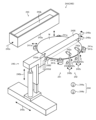
- FIG. 4 is a perspective view showing an example of first to fourth polishing portions 22A to 22D;
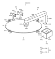
- FIG. 4 is a perspective view showing an example of first and second roll sponge cleaning units 24A and 24B;
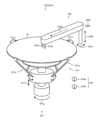
- FIG. 3 is a perspective view showing an example of first and second pen sponge cleaning units 24C and 24D.
- FIG. 3 is a perspective view showing an example of first and second drying sections 24E and 24F;
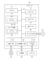
- 2 is a block diagram showing an example of a substrate processing apparatus 2;
- FIG. 3 is a hardware configuration diagram showing an example of a computer 900;
- FIG. 3 is a data configuration diagram showing an example of production history information 30 managed by a database device 3;
- FIG. 3 is a data configuration diagram showing an example of finishing test information 31 managed by the database device 3.
- FIG. 1 is a block diagram showing an example of a machine learning device 4 according to a first embodiment;
- FIG. It is a figure which shows an example of 10 A of 1st learning models, and 11 A of data for 1st learning.
- 4 is a flowchart showing an example of a machine learning method by the machine learning device 4;
- 1 is a block diagram showing an example of an information processing device 5 according to a first embodiment;
- FIG. 1 is a function explanatory diagram showing an example of an information processing device 5 according to a first embodiment;
- FIG. 5 is a flowchart showing an example of an information processing method by the information processing device 5; It is a block diagram which shows an example of the machine-learning apparatus 4a based on 2nd Embodiment. It is a figure which shows an example of the 2nd learning model 10B and the 2nd data for learning 11B.
- FIG. 5 is a block diagram showing an example of an information processing device 5a functioning as an information processing device 5a according to a second embodiment;
- FIG. 5 is a functional explanatory diagram showing an example of an information processing device 5a according to a second embodiment;
- FIG. 1 is an overall configuration diagram showing an example of a substrate processing system 1.
- the substrate processing system 1 performs a chemical mechanical polishing process (hereinafter referred to as "polishing") for flatly polishing the surface of the wafer W by pressing the substrate (hereinafter referred to as "wafer") W such as a semiconductor wafer against a polishing pad.
- a series of substrate processing including a cleaning process of cleaning the surface of the wafer W by bringing the polished wafer W into contact with a cleaning tool, and a drying process of drying the cleaned surface of the wafer W using a drying tool. function as a system to manage The cleaning process and the drying process constitute the finishing process, and the cleaning tool and the drying tool are included in the finishing tool.
- the substrate processing system 1 includes a substrate processing device 2, a database device 3, a machine learning device 4, an information processing device 5, and a user terminal device 6 as its main components.
- Each of the devices 2 to 6 is configured by, for example, a general-purpose or dedicated computer (see FIG. 8 described later), and is connected to a wired or wireless network 7 to store various data (partial data in FIG. 1). (shown by dashed arrows) can be mutually transmitted and received.
- the number of devices 2 to 6 and the connection configuration of the network 7 are not limited to the example shown in FIG. 1, and may be changed as appropriate.
- the substrate processing apparatus 2 is composed of a plurality of units, and performs a series of substrate processing on one or a plurality of wafers W, such as loading, polishing, cleaning, drying, film thickness measurement, and unloading. It is a device that performs each. At this time, the substrate processing apparatus 2 refers to apparatus setting information 265 consisting of a plurality of apparatus parameters respectively set for each unit, and substrate recipe information 266 that defines the operation states of the polishing process, the cleaning process, the drying process, and the like. while controlling the operation of each unit.
- the substrate processing apparatus 2 transmits various reports R to the database device 3, the user terminal device 6, etc. according to the operation of each unit.
- the various reports R include, for example, process information specifying the target wafer W when substrate processing was performed, apparatus status information indicating the status of each unit when each process was performed, substrate processing apparatus 2 event information detected in , operation information of a user (operator, production manager, maintenance manager, etc.) for the substrate processing apparatus 2, and the like.
- the database device 3 stores production history information 30 relating to the history of substrate processing using finishing tools for production, and a finishing process test (hereinafter referred to as a "finishing test") using a finishing tool for testing. ) is a device for managing finishing test information 31 relating to the history of when ) was performed.
- the database device 3 may store device setting information 265 and substrate recipe information 266. In that case, the substrate processing device 2 may refer to these information. good.
- the database device 3 receives various reports R from the substrate processing apparatus 2 as needed and registers them in the production history information 30 when the substrate processing apparatus 2 processes substrates using finishing tools for production. , the production history information 30 accumulates a report R relating to substrate processing.
- the database device 3 receives various reports R (including at least device status information) from the substrate processing apparatus 2 at any time when the substrate processing apparatus 2 performs a finishing test using a finishing tool for testing, and performs the finishing test.
- the finishing test information 31 accumulates the report R and the test results regarding the finishing tests.
- the finishing test may be performed by the substrate processing apparatus 2 for production, or may be performed by a finishing test apparatus (not shown) for testing that can reproduce the same finishing process as the substrate processing apparatus 2 .
- Various finishing tool measuring instruments (not shown) for measuring, for example, the degree of contamination, wear, and damage of the substrate holding mechanism, are included in the finishing tool for testing and the finishing test device. is provided, and the measured value of the finishing tool measuring instrument is registered in the finishing test information 31 as the test result.
- the machine learning device 4 operates mainly in the learning phase of machine learning, for example, acquires part of the finishing test information 31 from the database device 3 as first learning data 11A, and uses it in the information processing device 5.
- a first learning model 10A is generated by machine learning.
- the trained first learning model 10A is provided to the information processing device 5 via the network 7, a recording medium, or the like.
- the information processing device 5 operates as the subject of the inference phase of machine learning, and uses the first learning model 10A generated by the machine learning device 4 to perform finishing processing by the substrate processing device 2 as a finishing tool for production.
- the state of the substrate holding mechanism is predicted, and substrate holding mechanism state information, which is the result of the prediction, is transmitted to the database device 3, the user terminal device 6, and the like. do.
- the timing at which the information processing device 5 predicts the state information of the substrate holding mechanism may be after the finishing process is performed (post-prediction process) or during the finishing process (real-time prediction process). However, it may be before finishing processing is performed (prediction processing).
- the user terminal device 6 is a terminal device used by the user, and may be a stationary device or a portable device.
- the user terminal device 6, for example, receives various input operations via the display screen of an application program, web browser, etc., and various information via the display screen (e.g., event notification, substrate holding mechanism state information, production history information 30, finishing test information 31, etc.) are displayed.
- various information via the display screen e.g., event notification, substrate holding mechanism state information, production history information 30, finishing test information 31, etc.
- FIG. 2 is a plan view showing an example of the substrate processing apparatus 2.
- the substrate processing apparatus 2 includes a load/unload unit 21, a polishing unit 22, a substrate transfer unit 23, a finishing unit 24, a film thickness measurement unit 25, and a housing 20 which is substantially rectangular in plan view. and a control unit 26 .
- a first partition wall 200A separates the load/unload unit 21 from the polishing unit 22, the substrate transfer unit 23 and the finishing unit 24, and the substrate transfer unit 23 and the finishing unit 24 are separated from each other by a second separation wall 200A. It is partitioned by a partition wall 200B.
- the loading/unloading unit 21 includes first to fourth front loading sections 210A to 210D on which wafer cassettes (FOUPs, etc.) capable of vertically accommodating a large number of wafers W are placed, and A transfer robot 211 capable of moving up and down along the storage direction (vertical direction) of the wafer W, and a transfer robot 211 along the direction in which the first to fourth front load sections 210A to 210D are arranged (transverse direction of the housing 20). and a horizontal movement mechanism 212 for moving the .
- wafer cassettes FOUPs, etc.
- the transfer robot 211 carries wafer cassettes placed on each of the first to fourth front load sections 210A to 210D, the substrate transfer unit 23 (specifically, a lifter 232 to be described later), and the finishing unit 24 (specifically, First and second drying units 24E and 24F, which will be described later), and the film thickness measurement unit 25, are configured to be accessible, and upper and lower two-stage hands (not shown) for transferring the wafer W between them ).
- the lower hand is used when transferring wafers W before processing, and the upper hand is used when transferring wafers W after processing.
- a shutter (not shown) provided on the first partition 200A is opened and closed.
- the polishing unit 22 includes first to fourth polishing sections 22A to 22D for polishing (flattening) the wafer W, respectively.
- the first to fourth polishing parts 22A to 22D are arranged side by side along the longitudinal direction of the housing 20. As shown in FIG.
- FIG. 3 is a perspective view showing an example of the first to fourth polishing units 22A to 22D.
- the basic configurations and functions of the first to fourth polishing units 22A to 22D are common.
- Each of the first to fourth polishing units 22A to 22D includes a polishing table 220 that rotatably supports a polishing pad 2200 having a polishing surface, a wafer W that holds the wafer W, and a polishing pad on the polishing table 220 that holds the wafer W.
- a dresser 223 that contacts the polishing surface of 2200 to dress the polishing pad 2200 and an atomizer 224 that sprays cleaning fluid onto the polishing pad 2200 are provided.
- the polishing table 220 is supported by a polishing table shaft 220a and includes a rotational movement mechanism 220b that rotates the polishing table 220 about its axis, and a temperature control mechanism 220c that adjusts the surface temperature of the polishing pad 2200. .
- the top ring 221 is supported by a top ring shaft 221a that can move vertically.
- a rotation movement mechanism 221c rotates the top ring 221 about its axis, and a vertical movement mechanism moves the top ring 221 vertically. It includes a mechanism portion 221d and a rocking movement mechanism portion 221e for rotating (swinging) the top ring 221 around the support shaft 221b.
- the polishing fluid supply nozzle 222 is supported by a support shaft 222a.
- a rocking movement mechanism 222b rotates and moves the polishing fluid supply nozzle 222 around the support shaft 222a, and a flow control unit adjusts the flow rate of the polishing fluid.
- 222c and a temperature control mechanism 222d for adjusting the temperature of the polishing fluid.
- the polishing fluid is a polishing liquid (slurry) or pure water, and may further contain a chemical liquid, or may be a polishing liquid to which a dispersant is added.
- the dresser 223 is supported by a vertically movable dresser shaft 223a.
- the dresser 223 is supported by a rotational movement mechanism 223c that drives the dresser 223 to rotate about its axis, and a vertical movement mechanism 223d that vertically moves the dresser 223. , and a swing movement mechanism portion 223e for swinging and moving the dresser 223 around the support shaft 223b.
- the atomizer 224 is supported by a support shaft 224a and includes a swing movement mechanism section 224b that swings and moves the atomizer 224 around the support shaft 224a, and a flow rate adjustment section 224c that adjusts the flow rate of the cleaning fluid.
- the cleaning fluid is a mixed fluid of liquid (eg, pure water) and gas (eg, nitrogen gas) or liquid (eg, pure water).
- the wafer W is held by suction on the lower surface of the top ring 221 and moved to a predetermined polishing position on the polishing table 220 , the wafer W is applied to the polishing surface of the polishing pad 2200 to which the polishing fluid is supplied from the polishing fluid supply nozzle 222 . It is polished by being pressed by the top ring 221 .
- the substrate transfer unit 23 is, as shown in FIG. 2, first and second linear transporters horizontally movable along the direction in which the first to fourth polishing units 22A to 22D are arranged (the longitudinal direction of the housing 20). 230A, 230B, a swing transporter 231 disposed between the first and second linear transporters 230A, 230B, a lifter 232 disposed on the loading/unloading unit 21 side, and a finishing unit 24 side. and a temporary placing table 233 for the wafer W which has been processed.
- the first linear transporter 230A is arranged adjacent to the first and second polishing units 22A and 22B and has four transport positions (first to fourth transport positions in order from the load/unload unit 21 side). TP1 to TP4) for transporting the wafer W.
- the second transfer position TP2 is the position at which the wafer W is transferred to the first polishing section 22A
- the third transfer position TP3 is the position at which the wafer W is transferred to the second polishing section 22B. be.
- the second linear transporter 230B is arranged adjacent to the third and fourth polishing units 22C and 22D and has three transport positions (fifth to seventh transport positions in order from the load/unload unit 21 side). TP5 to TP7) for transporting the wafer W.
- the sixth transfer position TP6 is a position for transferring the wafer W to the third polishing section 22C
- the seventh transfer position TP7 is a position for transferring the wafer W to the fourth polishing section 22D.
- the swing transporter 231 is arranged adjacent to the fourth and fifth transport positions TP4 and TP5 and has a hand that can move between the fourth and fifth transport positions TP4 and TP5.
- the swing transporter 231 is a mechanism that transfers the wafer W between the first and second linear transporters 230A and 230B and temporarily places the wafer W on the temporary placement table 233 .
- the lifter 232 is a mechanism arranged adjacent to the first transfer position TP1 to transfer the wafer W to and from the transfer robot 211 of the load/unload unit 21 .
- a shutter (not shown) provided on the first partition 200A is opened and closed.
- finishing unit The finishing unit 24, as shown in FIG.
- First and second pen sponge cleaning units 24C and 24D which are arranged in two upper and lower stages, serve as substrate cleaning devices
- first and second pen sponge cleaning units 24C, 24D which are arranged in two upper and lower stages, serve as substrate drying devices for drying the wafers W after cleaning.
- second drying sections 24E and 24F, and first and second transfer sections 24G and 24H serve as substrate drying devices for drying the wafers W after cleaning.
- first and second transfer sections 24G and 24H for transferring the wafer W.
- the number and arrangement of the roll sponge cleaning units 24A and 24B, the pen sponge cleaning units 24C and 24D, the drying units 24E and 24F, and the transport units 24G and 24H are not limited to the example shown in FIG. good.
- Each section 24A to 24H of the finishing unit 24 is divided along the first and second linear transporters 230A and 230B, for example, the first and second roll sponge cleaning sections 24A and 24B, the second 1 conveying section 24G, first and second pen sponge washing sections 24C, 24D, second conveying section 24H, and first and second drying sections 24E, 24F in this order (from the load/unload unit 21 farthest order).
- the finishing unit 24 subjects the wafer W after the polishing process to primary cleaning processing by either the first and second roll sponge cleaning units 24A and 24B, and the first and second pen sponge cleaning units 24C and 24D. A secondary cleaning process by one of them and a drying process by one of the first and second drying units 24E and 24F are performed in this order.
- the roll sponge 2400 and pen sponge 2401 are made of synthetic resin such as PVA and nylon, and have a porous structure.
- the roll sponge 2400 and the pen sponge 2401 function as cleaning tools for scrub cleaning the wafer W, and are the first and second roll sponge cleaning units 24A and 24B and the first and second pen sponge cleaning units 24C. , 24D, respectively.
- the first transport section 24G includes a first transport robot 246A that can move vertically.
- the first transport robot 246A operates on the temporary table 233 of the substrate transport unit 23, the first and second roll sponge cleaning units 24A and 24B, and the first and second pen sponge cleaning units 24C and 24D. It is configured to be accessible and has upper and lower two-stage hands for transferring wafers W therebetween. For example, the lower hand is used when transferring wafers W before cleaning, and the upper hand is used when transferring wafers W after cleaning.
- a shutter (not shown) provided on the second partition 200B is opened and closed.
- the second transport section 24H includes a second transport robot 246B that can move vertically.
- the second transfer robot 246B is configured to be able to access the first and second pen sponge cleaning units 24C, 24D and the first and second drying units 24E, 24F, between which the wafer W is transferred. Equipped with a hand for passing
- FIG. 4 is a perspective view showing an example of the first and second roll sponge cleaning parts 24A, 24B.
- the basic configurations and functions of the first and second roll sponge cleaning units 24A and 24B are common.
- the first and second roll sponge cleaning units 24A and 24B have a pair of roll sponges 2400 arranged vertically so as to sandwich the surfaces to be cleaned (front and back surfaces) of the wafer W.
- Each of the first and second roll sponge cleaning units 24A and 24B can rotate a substrate holding unit 241 that holds the wafer W, a cleaning fluid supply unit 242 that supplies substrate cleaning fluid to the wafer W, and a roll sponge 2400.
- a substrate cleaning unit 240 that supports the substrate and cleans the wafer W by bringing the roll sponge 2400 into contact with the wafer W;
- a cleaning tool cleaning unit 243 that cleans (self-cleans) the roll sponge 2400 with a cleaning tool cleaning fluid; and an environment sensor 244 that measures the condition of the internal space of the housing 20 where the operation is performed.
- the substrate holding unit 241 includes a substrate holding mechanism unit 241a that holds a plurality of locations on the side edge of the wafer W, and a substrate rotation mechanism unit that rotates the wafer W around a third rotation axis perpendicular to the surface to be cleaned of the wafer W. 241b.
- the substrate holding mechanism part 241a is four rollers, and at least one roller is configured to be movable with respect to the side edge of the wafer W in the holding direction or separation direction.
- the substrate rotation mechanism part 241b is two drive rollers.
- the driving rollers that constitute the substrate rotation mechanism 241b also serve as the substrate holding mechanism 241a that holds the wafer W.
- the substrate holding section 241 may be a substrate holding mechanism section 241a composed of a plurality of rollers and a substrate rotation mechanism section 241b composed of at least one drive roller.
- the cleaning fluid supply unit 242 includes a cleaning fluid supply nozzle 242a that supplies the substrate cleaning fluid to the surface to be cleaned of the wafer W, a swinging movement mechanism unit 242b that swivels the cleaning fluid supply nozzle 242a, and a substrate cleaning fluid flow rate and A flow control unit 242c for controlling pressure and a temperature control mechanism unit 242d for controlling the temperature of the substrate cleaning fluid are provided.
- the substrate cleaning fluid may be either pure water (rinse liquid) or chemical solution, and the cleaning fluid supply nozzle 242a is provided with separate nozzles for pure water and chemical solutions, as shown in FIG. may Also, the substrate cleaning fluid may be a liquid, a two-fluid mixture of a liquid and a gas, or may contain a solid such as dry ice.
- the substrate cleaning section 240 includes a cleaning tool rotation mechanism section 240a that rotates the roll sponge 2400 around a first rotation axis parallel to the surface to be cleaned of the wafer W, and the height of the pair of roll sponges 2400 and the separation distance between the two.
- a vertical movement mechanism 240b for vertically moving at least one of the pair of roll sponges 2400 and a linear movement mechanism 240c for linearly moving the pair of roll sponges 2400 in the horizontal direction are provided.
- the vertical movement mechanism portion 240b and the linear movement mechanism portion 240c function as a cleaning tool movement mechanism portion that moves the relative positions of the roll sponge 2400 and the surface of the wafer W to be cleaned.
- the cleaning tool cleaning part 243 is arranged at a position not interfering with the wafer W, and accommodated in the cleaning tool cleaning tank 243a capable of storing and discharging the cleaning tool cleaning fluid and the cleaning tool cleaning tank 243a.
- a flow control unit 243d is provided to control the flow rate and pressure of the cleaning tool cleaning fluid discharged to the outside.
- the cleaning tool cleaning fluid may be pure water (rinse liquid) or chemical solution.
- the environment sensor 244 includes, for example, a temperature sensor 244a and a humidity sensor 244b.
- a camera image sensor capable of photographing the surface of the wafer W, the roll sponge 2400, etc. during the cleaning process or before and after the cleaning process may be provided.
- the wafer W is rotated by the substrate rotating mechanism 241b while being held by the substrate holding mechanism 241a. Then, in a state in which the substrate cleaning fluid is supplied to the surface to be cleaned of the wafer W from the cleaning fluid supply nozzle 242a, the roll sponge 2400 rotated around the axis by the cleaning tool rotation mechanism 240a is applied to the surface to be cleaned of the wafer W. The wafer W is cleaned by the sliding contact.
- the substrate cleaning unit 240 moves the roll sponge 2400 to the cleaning tool cleaning tank 243a, for example, rotates the roll sponge 2400, presses it against the cleaning tool cleaning plate 243b, or controls the cleaning tool cleaning fluid by the flow control unit 243d. is supplied to the roll sponge 2400, the roll sponge 2400 is cleaned.
- FIG. 5 is a perspective view showing an example of the first and second pen sponge cleaning units 24C and 24D.
- the basic configurations and functions of the first and second pen sponge cleaning units 24C and 24D are common.
- Each of the first and second pen sponge cleaning units 24C and 24D can rotate a substrate holding unit 241 that holds the wafer W, a cleaning fluid supply unit 242 that supplies substrate cleaning fluid to the wafer W, and a pen sponge 2401.
- a substrate cleaning unit 240 that supports the substrate and cleans the wafer W by bringing the pen sponge 2401 into contact with the wafer W, a cleaning tool cleaning unit 243 that cleans (self-cleans) the pen sponge 2401 with cleaning fluid, and a cleaning process and an environment sensor 244 that measures the condition of the internal space of the housing 20 where the operation is performed.
- the pen sponge cleaning units 24C and 24D will be described below, focusing on the differences from the roll sponge cleaning units 24A and 24B.
- the substrate holding part 241 includes a substrate holding mechanism part 241c that holds a plurality of positions on the side edge of the wafer W, and a substrate rotation mechanism part that rotates the wafer W around a third rotation axis perpendicular to the surface to be cleaned of the wafer W. 241d.
- the substrate holding mechanism part 241c is four rollers, and at least one roller is configured to be movable with respect to the side edge of the wafer W in the holding direction or the separation direction.
- 241d are two drive rollers.
- the driving rollers that constitute the substrate rotation mechanism 241b also serve as the substrate holding mechanism 241a that holds the wafer W.
- the substrate holding section 241 may be a substrate holding mechanism section 241c composed of a plurality of rollers and a substrate rotation mechanism section 241d composed of at least one drive roller.
- the cleaning fluid supply section 242 is configured in the same manner as in FIG. 4, and includes a cleaning fluid supply nozzle 242a, a rocking movement mechanism section 242b, a flow control section 242c, and a temperature control mechanism section 242d.
- the substrate cleaning section 240 includes a cleaning tool rotation mechanism section 240d that rotates the pen sponge 2401 around a second rotation axis perpendicular to the surface to be cleaned of the wafer W, and a vertical movement mechanism section 240e that vertically moves the pen sponge 2401. and a rocking movement mechanism 240f for rotating and moving the pen sponge 2401 in the horizontal direction.
- the vertical movement mechanism portion 240e and the swing movement mechanism portion 240f function as a cleaning tool movement mechanism portion that moves the relative positions of the pen sponge 2401 and the surface of the wafer W to be cleaned.
- the cleaning tool cleaning part 243 is arranged at a position not interfering with the wafer W, and accommodated in the cleaning tool cleaning tank 243e capable of storing and discharging the cleaning tool cleaning fluid, and the cleaning tool cleaning tank 243e.
- a flow control unit 243h is provided to control the flow rate and pressure of the cleaning tool cleaning fluid discharged to the outside.
- the environment sensor 244 includes, for example, a temperature sensor 244a and a humidity sensor 244b.
- a camera image sensor capable of photographing the surface of the wafer W, the pen sponge 2401, etc. during the cleaning process or before and after the cleaning process may be provided.
- the wafer W is rotated by the substrate rotating mechanism 241d while being held by the substrate holding mechanism 241c. Then, while the substrate cleaning fluid is being supplied from the cleaning fluid supply nozzle 242a to the surface to be cleaned of the wafer W, the pen sponge 2401 rotated around the axis by the cleaning tool rotation mechanism 240d is applied to the surface to be cleaned of the wafer W. The wafer W is cleaned by the sliding contact. After that, the substrate cleaning unit 240 moves the pen sponge 2401 to the cleaning tool cleaning tank 243e, for example, rotates the pen sponge 2401, presses it against the cleaning tool cleaning plate 243f, or controls the cleaning tool cleaning fluid by the flow control unit 243h. is supplied to the pen sponge 2401 to clean the pen sponge 2401 .
- FIG. 6 is a perspective view showing an example of the first and second drying sections 24E, 24F.
- the basic configurations and functions of the first and second drying sections 24E and 24F are common.
- Each of the first and second drying sections 24E and 24F includes a substrate holding section 241 that holds the wafer W, a drying fluid supply section 245 that supplies the substrate drying fluid to the wafer W, and the housing 20 where the drying process is performed. and an environment sensor 244 that measures the state of the interior space.
- the substrate holding unit 241 includes a substrate holding mechanism unit 241e that holds a plurality of positions on the side edge of the wafer W, and a substrate rotation mechanism unit that rotates the wafer W around a third rotation axis perpendicular to the surface to be cleaned of the wafer W. 241g.
- the substrate holding mechanism part 241e is installed such that one end thereof rotates about a horizontal axis with respect to the vertical movement mechanism part 241f that moves in the vertical direction, and the other end can be brought into contact with and separated from the peripheral edge of the wafer W. It is formed in a gripping part such as a chuck.
- the substrate holding mechanism part 241e constitutes an umbrella mechanism in which the gripping part moves in contact with the wafer W or in the separation direction as the vertical movement mechanism 241f moves in the vertical direction. Note that the gripping portion may be configured by a roller.
- the dry fluid supply unit 245 includes a dry fluid supply nozzle 245a that supplies the substrate dry fluid to the surface to be cleaned of the wafer W, a vertical movement mechanism unit 245b that vertically moves the dry fluid supply nozzle 245a, and the dry fluid supply nozzle 245a. , a flow control unit 245d for adjusting the flow rate and pressure of the substrate drying fluid, and a temperature control mechanism unit 245e for adjusting the temperature of the substrate drying fluid.
- the vertical movement mechanism portion 245b and the rocking movement mechanism portion 245c function as a drying fluid supply nozzle movement mechanism portion that moves the relative positions of the drying fluid supply nozzle 245a and the surface of the wafer W to be cleaned.
- the substrate drying fluid is, for example, IPA vapor and pure water (rinse liquid), and as shown in FIG. may have been Also, the substrate drying fluid may be a liquid, a two-fluid mixture of a liquid and a gas, or a solid such as dry ice.
- the environment sensor 244 includes a temperature sensor 244a and a humidity sensor 244b.
- a camera image sensor capable of photographing the surface of the wafer W, etc. during the drying process or before and after the drying process may be provided.
- the wafer W is rotated by the substrate rotating mechanism 241g while being held by the substrate holding mechanism 241e. Then, the drying fluid supply nozzle 245a is moved toward the side edge of the wafer W (outside in the radial direction) while the substrate drying fluid is being supplied from the drying fluid supply nozzle 245a to the surface of the wafer W to be cleaned. After that, the wafer W is dried by being rotated at high speed by the substrate rotation mechanism section 241e.
- the specific configurations of the mechanism units 240f, 242b, 245c and the cleaning tool rotation mechanism units 240a, 240d are omitted, for example, modules for generating driving force such as motors and air cylinders, linear guides, ball screws, It is configured by appropriately combining driving force transmission mechanisms such as gears, belts, couplings and bearings, and sensors such as linear sensors, encoder sensors, limit sensors and torque sensors.
- 4 to 6 omit specific configurations of the flow control units 243c, 243d, 243g, 243h, and 245d. It is configured by appropriately combining sensors such as a sensor, a pressure sensor, and a liquid level sensor. 4 to 6 omit the specific configuration of the temperature control mechanism units 242d and 245e, but for example, temperature control (contact or non-contact) modules such as heaters and heat exchangers, It is configured by appropriately combining sensors such as a temperature sensor and a current sensor.
- the film thickness measurement unit 25 is a measuring device for measuring the film thickness of the wafer W before or after polishing, and is composed of, for example, an optical film thickness measuring device, an eddy current film thickness measuring device, or the like. Transfer of the wafer W to each film thickness measurement module is performed by the transfer robot 211 .
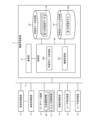
- FIG. 7 is a block diagram showing an example of the substrate processing apparatus 2. As shown in FIG. The control unit 26 is electrically connected to each of the units 21 to 25 and functions as a control section that controls the units 21 to 25 in an integrated manner.
- the control system (modules, sensors, sequencers) of the finishing unit 24 will be described below as an example, but since the other units 21 to 23 and 25 have the same basic configuration and functions, their description will be omitted.
- the finishing unit 24 includes subunits provided in the finishing unit 24 (for example, first and second roll sponge cleaning units 24A and 24B, first and second pen sponge cleaning units 24C and 24D, first and second Drying units 24E, 24F, first and second conveying units 24G, 24H, etc.), and a plurality of modules 2471 to 247r to be controlled, and a plurality of modules 2471 to 247r, respectively.
- a plurality of sensors 2481 to 248s for detecting data (detection values) necessary for controlling the modules 2471 to 247r, and a sequencer 249 for controlling the operations of the modules 2471 to 247r based on the detection values of the sensors 2481 to 248s. Prepare.
- the sensors 2481 to 248s of the finishing unit 24 include, for example, a sensor that detects the number of rotations of the wafer W itself, a sensor that detects the count number of measured portions formed on the wafer W, and substrate rotation mechanism portions 241b, 241d, and 241g.
- sensor for detecting the number of rotations of the substrate rotating mechanism units 241b, 241d and 241g sensor for detecting the rotational torque of the substrate rotating mechanism units 241b, 241d and 241g, sensor for detecting positional coordinates of the substrate holding mechanism units 241a, 241c and 241e for holding the wafer W, vertical movement mechanism A sensor for detecting the movement distance of the portion 241f, a sensor for detecting the holding load or pressure when the substrate holding mechanism portions 241a, 241c, and 241e hold the substrate, and a sensor for detecting the number of revolutions of the substrate holding mechanism portions 241a, 241c, and 241e.
- sensors sensors, sensors for detecting the rotation speed of the substrate holding mechanism portions 241a, 241c, and 241e, sensors for detecting the rotational torque of the substrate holding mechanism portions 241a, 241c, and 241e, sensors for detecting the movement distance of the vertical movement mechanism 241f, and the like.
- the control unit 26 includes a control section 260 , a communication section 261 , an input section 262 , an output section 263 and a storage section 264 .
- the control unit 26 is composed of, for example, a general-purpose or dedicated computer (see FIG. 8 described later).
- the communication unit 261 is connected to the network 7 and functions as a communication interface for transmitting and receiving various data.
- the input unit 262 receives various input operations, and the output unit 263 functions as a user interface by outputting various information via the display screen, signal tower lighting, and buzzer sound.
- the storage unit 264 stores various programs (operating system (OS), application programs, web browsers, etc.) and data (apparatus setting information 265, substrate recipe information 266, etc.) used in the operation of the substrate processing apparatus 2 .
- the equipment setting information 265 and substrate recipe information 266 are data that can be edited by the user via the display screen.
- the control unit 260 controls a plurality of sensors 2181 to 218q, 2281 to 228s, 2381 to 238u, 2481 to 248w, 2581 through a plurality of sequencers 219, 229, 239, 249, and 259 (hereinafter referred to as "sequencer group”).
- 258y hereinafter referred to as “sensor group”
- module group a plurality of modules 2171-217p, 2271-227r, 2371-237t, 2471-247v, and 2571-257x.
- a series of substrate processing such as loading, polishing, cleaning, drying, film thickness measurement, and unloading are performed by operating in conjunction with each other.
- FIG. 8 is a hardware configuration diagram showing an example of the computer 900. As shown in FIG.
- Each of the control unit 26 of the substrate processing apparatus 2, the database device 3, the machine learning device 4, the information processing device 5, and the user terminal device 6 is configured by a general-purpose or dedicated computer 900.
- the computer 900 includes, as its main components, a bus 910, a processor 912, a memory 914, an input device 916, an output device 917, a display device 918, a storage device 920, a communication I/F (interface). It has a section 922 , an external equipment I/F section 924 , an I/O (input/output) device I/F section 926 and a media input/output section 928 . Note that the above components may be omitted as appropriate depending on the application for which the computer 900 is used.
- the processor 912 is composed of one or more arithmetic processing units (CPU (Central Processing Unit), MPU (Micro-processing unit), DSP (digital signal processor), GPU (Graphics Processing Unit), etc.), and the entire computer 900 It operates as a control unit that supervises the
- the memory 914 stores various data and programs 930, and is composed of, for example, a volatile memory (DRAM, SRAM, etc.) functioning as a main memory, a non-volatile memory (ROM), a flash memory, and the like.
- the input device 916 is composed of, for example, a keyboard, mouse, numeric keypad, electronic pen, etc., and functions as an input unit.
- the output device 917 is configured by, for example, a sound (voice) output device, a vibration device, or the like, and functions as an output unit.
- a display device 918 is configured by, for example, a liquid crystal display, an organic EL display, electronic paper, a projector, or the like, and functions as an output unit.
- the input device 916 and the display device 918 may be configured integrally like a touch panel display.
- the storage device 920 is composed of, for example, an HDD, SSD (Solid State Drive), etc., and functions as a storage unit.
- the storage device 920 stores various data necessary for executing the operating system and programs 930 .
- the communication I/F unit 922 is connected to a network 940 (which may be the same as the network 7 in FIG. 1) such as the Internet or an intranet by wire or wirelessly, and exchanges data with other computers according to a predetermined communication standard. functions as a communication unit that transmits and receives.
- the external device I/F unit 924 is connected to the external device 950 such as a camera, printer, scanner, reader/writer, etc. by wire or wirelessly, and serves as a communication unit that transmits and receives data to and from the external device 950 according to a predetermined communication standard. Function.
- the I/O device I/F unit 926 is connected to I/O devices 960 such as various sensors and actuators, and exchanges with the I/O devices 960, for example, detection signals from sensors and control signals to actuators. functions as a communication unit that transmits and receives various signals and data.
- the media input/output unit 928 is composed of, for example, a drive device such as a DVD drive and a CD drive, and reads and writes data from/to media (non-temporary storage media) 970 such as DVDs and CDs.
- the processor 912 calls the program 930 stored in the storage device 920 to the memory 914 and executes it, and controls each part of the computer 900 via the bus 910 .
- the program 930 may be stored in the memory 914 instead of the storage device 920 .
- the program 930 may be recorded on the media 970 in an installable file format or executable file format and provided to the computer 900 via the media input/output unit 928 .
- Program 930 may be provided to computer 900 by downloading via network 940 via communication I/F section 922 .
- the computer 900 may implement various functions realized by the processor 912 executing the program 930 by hardware such as FPGA and ASIC, for example.
- the computer 900 is, for example, a stationary computer or a portable computer, and is an arbitrary form of electronic equipment.
- the computer 900 may be a client-type computer, a server-type computer, or a cloud-type computer.
- the computer 900 may be applied to devices other than the devices 2-6.
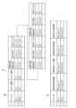
- FIG. 9 is a data configuration diagram showing an example of production history information 30 managed by the database device 3.
- the production history information 30 includes, for example, a wafer history table 300 for each wafer W and an apparatus status in the finishing process as a table in which reports R obtained when substrate processing for main production is performed are classified and registered. and a finishing history table 301 relating to information.
- the finishing history table 301 includes a cleaning history table regarding device state information in cleaning processing and a drying history table regarding device state information in drying processing.
- the production history information 30 includes a polishing history table regarding apparatus status information in polishing processing, an event history table regarding event information, an operation history table regarding operation information, and the like, but detailed description thereof will be omitted.
- Each record of the wafer history table 300 registers, for example, a wafer ID, cassette number, slot number, start time and end time of each process, used unit ID, and the like.
- the polishing process, the cleaning process, and the drying process are illustrated in FIG. 9, the other processes are similarly registered.
- Each record of the finishing history table 301 registers, for example, a wafer ID, substrate rotation speed information and substrate rotation torque information constituting substrate rotation state information, substrate holding position information, substrate pressing load information, and the like.
- the substrate rotation speed information is information indicating the rotation speed of the wafer W in the finishing process.
- the substrate rotation speed information is, for example, the detection value of a sensor that measures the rotation speed of the wafer W itself, the detection value of a sensor that measures the rotation speed using a side portion to be measured such as a notch formed or installed on the wafer W, These are detection values of sensors that measure the number of rotations of the substrate rotation mechanism units 241b, 241d, and 241g that rotate the wafer W, and the like.
- the substrate rotation torque information is information indicating the rotation torque of the wafer W itself in the finishing process.
- the substrate rotation torque information is, for example, detection values of sensors that measure the torque of the substrate rotation mechanisms 241b, 241d, and 241g that rotate the wafer W, and the like.
- the substrate holding position information is information indicating the coordinates of the positions where the substrate holding mechanisms 241a, 241c, and 241e hold the wafer W.
- the substrate holding position information may be obtained by measuring a horizontal positional deviation from a preset reference position for holding the wafer W at preset position coordinates.
- the substrate holding position information is, for example, detection values of sensors that measure the positions at which the wafers W are held by the substrate holding mechanisms 241a, 241c, and 241e.
- substrate holding position information may measure the movement distance of the up-and-down movement mechanism part 241f.
- the substrate holding position information may be information obtained by measuring a vertical positional deviation from a preset reference position where the substrate holding mechanisms 241a, 241c, and 241e hold the wafer W.
- the substrate pressing load information is information indicating the load with which the substrate holding mechanisms 241a, 241c, and 241e press the wafer W.
- the substrate pressing load information may be obtained by measuring the load using a load cell, or by measuring the pneumatic pressure of the air when using air for pressing the wafer W.
- time-series data of each sensor (or time series data of each module) can be obtained as the apparatus state of the substrate processing apparatus 2 when the wafer W specified by the wafer ID has undergone the finishing process. series data) can be extracted.
- FIG. 10 is a data configuration diagram showing an example of the finishing test information 31 managed by the database device 3.
- the finish test information 31 includes a finish test table 310 in which reports R and test results obtained when a finish test is performed using a substrate holder for testing and a finish test apparatus are classified and registered.
- Each record of the finishing test table 310 registers, for example, a test ID, substrate rotation speed information and substrate rotation torque information constituting substrate rotation state information, substrate holding position information, substrate pressing load information, test result information, and the like.
- the substrate rotation speed information, the substrate rotation torque information, the substrate holding position information, and the substrate pressing load information, which constitute the substrate rotation state information of the finishing test table 310 are information indicating the state of each part in the finishing test. Since the configuration is the same as that of the finishing history table 301, detailed description will be omitted.
- the test result information is information indicating the state of the test substrate holding mechanism when the finishing process is performed in the finishing test.
- the test result information is measured values sampled at predetermined time intervals by a substrate holding mechanism portion for testing or a substrate holding mechanism portion measuring device provided in a substrate holding mechanism portion testing apparatus.
- the test result information shown in FIG. 10 includes the degree of contamination, the degree of wear, and the degree of damage at each time t1, t2, . . . , . degrees TR1, TR2, TR3, respectively.
- the test result information may be a measured value that is the result of measurement by the substrate holding mechanism measurement device, or may be a substrate holding device for testing using a camera mounted on an optical microscope or a scanning electron microscope (SEM). It may be based on the results of image processing in which the mechanical section is photographed at predetermined time intervals and image processing is performed on each photographed image, or the results of experimental analysis conducted by an experimenter. Further, the test result information may be collected in a single finishing test in which the finishing process is continuously performed from the start to the end thereof, or may be collected at a predetermined time after the finishing process is started. By repeating the finishing test until the predetermined time is gradually lengthened, the data may be collected from a plurality of finishing tests.
- the finishing test table 310 By referring to the finishing test table 310, the states of the substrate holding mechanism portions 241a, 241c, and 241e when the finishing process is performed using the test substrate holding portion in the finishing test specified by the test ID are shown. It is possible to extract time-series data (or time-series data of each module) and time-series data indicating the state of the substrate holding mechanism for testing at that time.
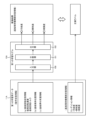
- FIG. 11 is a block diagram showing an example of the machine learning device 4 according to the first embodiment.
- the machine learning device 4 includes a control unit 40 , a communication unit 41 , a learning data storage unit 42 and a trained model storage unit 43 .
- the control unit 40 functions as a learning data acquisition unit 400 and a machine learning unit 401.
- the communication unit 41 is connected to external devices (for example, the substrate processing device 2, the database device 3, the information processing device 5, the user terminal device 6, the finishing test device (not shown), etc.) via the network 7, and various function as a communication interface for sending and receiving data.
- the learning data acquisition unit 400 is connected to an external device via the communication unit 41 and the network 7, and is composed of operation state information as input data and board holding mechanism state information as output data.
- the first learning data 11A is data used as teacher data (training data), verification data, and test data in supervised learning. Further, the substrate holding mechanism state information is data used as a correct label in supervised learning.
- the learning data storage unit 42 is a database that stores a plurality of sets of the first learning data 11A acquired by the learning data acquisition unit 400. Note that the specific configuration of the database that constitutes the learning data storage unit 42 may be appropriately designed.
- the machine learning unit 401 performs machine learning using multiple sets of first learning data 11A stored in the learning data storage unit 42 . That is, the machine learning section 401 inputs a plurality of sets of the first learning data 11A to the first learning model 10A, and compares the operation state information and the substrate holding mechanism section state information included in the first learning data 11A. By having the first learning model 10A learn the correlation, the learned first learning model 10A is generated.
- the trained model storage unit 43 is a database that stores the trained first learning model 10A (specifically, the adjusted weight parameter group) generated by the machine learning unit 401.
- the learned first learning model 10A stored in the learned model storage unit 43 is provided to the actual system (for example, the information processing device 5) via the network 7, a recording medium, or the like.
- the learning data storage unit 42 and the trained model storage unit 43 are shown as separate storage units in FIG. 11, they may be configured as a single storage unit.
- the number of first learning models 10A stored in the learned model storage unit 43 is not limited to one. Even if a plurality of learning models with different conditions are stored, such as differences in the mechanisms of the units 241a, 241c, and 241e, the types of data included in the operating state information, and the types of data included in the substrate holding mechanism unit state information. good.
- the learning data storage unit 42 may store a plurality of types of learning data having data configurations respectively corresponding to a plurality of learning models with different conditions.
- FIG. 12 is a diagram showing an example of the first learning model 10A and the first learning data 11A.
- the first learning data 11A used for machine learning of the first learning model 10A is composed of operation state information and substrate holding mechanism portion state information (condition information).
- the first learning model 10A and the first learning data 11A correspond to the roll sponge cleaning units 24A and 24B using the roll sponge 2400 and the pen sponge cleaning unit using the pen sponge 2401. At least three types, one corresponding to 24C and 24D and one corresponding to drying units 24E and 24F, are prepared.
- the operation state information constituting the first learning data 11A includes substrate rotation state information indicating the rotation state of the wafer W, substrate holding position information indicating the positions at which the substrate holding mechanisms 241a, 241c, and 241e hold the wafer W, and substrate pressing load information indicating the load with which the wafer W is pressed by the substrate holding mechanisms 241a, 241c, and 241e.
- the substrate rotation state information included in the operating state information includes substrate rotation speed information indicating the rotation speed of the wafer W and substrate rotation torque information indicating the rotation torque of the wafer W.
- the substrate rotation speed information is information indicating the rotation speed of the wafer W.
- the substrate rotation speed information includes, for example, the rotation speed of the wafer W itself, the count number of side portions to be measured such as notches formed or placed on the wafer W, and the rotation of the substrate rotation mechanisms 241b, 241d, and 241g that rotate the wafer W. number is fine.
- the substrate rotation torque information may be the torque of the substrate rotation mechanism units 241b, 241d, and 241g that rotate the wafer W, for example.
- the substrate holding position information included in the operating state information includes the positions at which the wafers W are held by the substrate holding mechanisms 241a, 241c, and 241e.
- position coordinates may be set around the rotation center of the wafer W or the holding position for holding the wafer W, and may be indicated by the distance of the horizontal displacement from the initial holding position.
- a horizontal positional deviation from a preset reference position for holding the wafer W may be measured.
- the substrate holding position information may be obtained by measuring the movement distance of the vertical movement mechanism section 241f.
- the substrate holding position information may be information obtained by measuring a vertical positional deviation from a preset reference position where the substrate holding mechanisms 241a, 241c, and 241e hold the wafer W.
- the substrate pressing load information included in the operating state information includes the load with which the substrate holding mechanisms 241a, 241c, and 241e press the wafer W.
- the substrate pressing load information may be obtained by measuring the pressing load using a load cell, or by measuring air pressure when air is used to press the wafer W. FIG.
- the operating state information may further include device internal environment information indicating the environment of the space in which the finishing process is performed. , and humidity. Further, the operation state information may further include processing performance information indicating the performance of finishing processing. It includes at least one of the accumulated number of used wafers W and the accumulated used time when finishing processing is performed using the substrate holding mechanism portions 241a, 241c, and 241e.
- the substrate holding mechanism portion state information constituting the first learning data 11A is information indicating the states of the substrate holding mechanism portions 241a, 241c, and 241e when the substrate processing apparatus 2 operates in the operating state indicated by the operating state information. is.
- the substrate holding mechanism portion state information includes at least one of the degree of contamination, wear, and damage of the substrate holding mechanism portions 241a, 241c, and 241e.
- the learning data acquisition unit 400 acquires the first learning data 11A by referring to the finishing test information 31 and accepting user input operations through the user terminal device 6 as necessary.
- the learning data acquisition unit 400 refers to the finishing test table 310 of the finishing test information 31 to obtain substrate rotation state information, substrate holding position information, and , board pressing load information is acquired as operation state information.
- operation state information is obtained as time-series data of a group of sensors as shown in FIG.
- a command value to the module may be used, a parameter converted from the detected value of the sensor or the command value to the module may be used, or based on the detected values of a plurality of sensors. Calculated parameters may be used.
- the operating state information may be acquired as time-series data for the entire finishing processing period, may be acquired as time-series data for a target period that is part of the finishing processing period, or may be acquired as time-series data for a target period that is part of the finishing processing period. It may be acquired as time point data.
- the data structure of the input data in the first learning model 10A and the first learning data 11A may be changed as appropriate.
- the learning data acquisition unit 400 refers to the finishing test table 310 of the finishing test information 31 to obtain test result information (substrate holding mechanism unit measurement Time-series data of the device (FIG. 10)) is acquired as substrate holding mechanism state information for the above operation state information.
- test result information substrate holding mechanism unit measurement Time-series data of the device (FIG. 10)
- the substrate holding mechanism portion measuring device is a measuring device capable of planar measurement of the substrate holding mechanism portions 241a, 241c, and 241e
- the learning data acquisition portion 400 obtains planar measurement values from the substrate. Acquired as holding mechanism state information.
- the substrate holding mechanism state information is condition information as shown in FIG. 12, but it may include at least one of the degree of contamination, the degree of wear, and the degree of breakage. . Further, the substrate holding mechanism portion state information may be calculated by substituting the measured value of the substrate holding mechanism portion measuring instrument into a predetermined calculation formula. Furthermore, when the operation state information is acquired as time-series data for the entire finishing process period or time-series data for a target period that is a part of the finishing process period, the substrate holding mechanism state information It may be acquired as time-series data for the entire processing period or time-series data for the target period, or may be acquired as point-in-time data at the end of the finishing process or point-in-time data at the target point.
- the substrate holding mechanism state information may be acquired as point-in-time data at the specific target point in time.
- the data structure of the output data in the first learning model 10A and the first learning data 11A may be changed as appropriate.
- the first learning model 10A employs, for example, a neural network structure, and includes an input layer 100, an intermediate layer 101, and an output layer 102.
- a synapse (not shown) connecting each neuron is provided between each layer, and a weight is associated with each synapse.
- a set of weight parameters consisting of the weight of each synapse is adjusted by machine learning.
- the input layer 100 has a number of neurons corresponding to the operating state information as input data, and each value of the operating state information is input to each neuron.
- the output layer 102 has a number of neurons corresponding to the substrate holding mechanism state information as output data, and outputs the prediction result (inference result) of the substrate holding mechanism state information for the operation state information as output data.
- the substrate holding mechanism state information is output as numerical values normalized to a predetermined range (eg, 0 to 1).
- the board holding mechanism state information is normalized to a predetermined range (for example, 0 to 1) as a score (accuracy) for each class. are output as numerical values.
- Inference results corresponding to numerical values are set in advance in the "predetermined range (0 to 1)".
- the inference result "predetermined range (0 to 1)" may be divided into a plurality of ranges, and the degree of contamination may be set for each divided range.
- a predetermined threshold value is set within a "predetermined range (0 to 1)", which is the result of inference. If it exceeds the value, it should be set as "contaminated”. The degree of contamination or the presence or absence of contamination is output according to the inference result.
- FIG. 13 is a flow chart showing an example of a machine learning method by the machine learning device 4. As shown in FIG.
- step S100 the learning data acquisition unit 400 acquires a desired number of first learning data 11A from the finishing test information 31 or the like as a preparation for starting machine learning, and acquires the acquired first learning data 11A.
- One learning data 11A is stored in the learning data storage unit 42 .
- the number of first learning data 11A prepared here may be set in consideration of the inference accuracy required for the finally obtained first learning model 10A.
- step S110 the machine learning unit 401 prepares the first learning model 10A before learning to start machine learning.
- the first learning model 10A before learning prepared here is composed of a neural network model, and the weight of each synapse is set to an initial value.
- step S120 the machine learning unit 401, for example, randomly selects one set of first learning data 11A from the plurality of sets of first learning data 11A stored in the learning data storage unit 42. get.
- step S130 the machine learning unit 401 converts the operating state information (input data) included in the set of first learning data 11A into the prepared first learning before (or during learning) learning. Input to the input layer 100 of the model 10A. As a result, substrate holding mechanism state information (output data) is output from the output layer 102 of the first learning model 10A as an inference result. It is generated by model 10A. Therefore, in the pre-learning (or during learning) state, the output data output as the inference result indicates information different from the board holding mechanism portion state information (correct label) included in the first learning data 11A.
- step S140 the machine learning unit 401 acquires the substrate holding mechanism state information (correct label) included in the set of first learning data 11A acquired in step S120, and the output layer in step S130.
- Machine learning is performed by comparing the state information (output data) of the substrate holding mechanism output as the result of inference and adjusting the weight of each synapse (back promotion). Thereby, the machine learning unit 401 causes the first learning model 10A to learn the correlation between the operation state information and the substrate holding mechanism state information.
- step S150 the machine learning unit 401 determines whether or not a predetermined learning end condition is satisfied, for example, the substrate holding mechanism unit state information (correct label) included in the first learning data 11A, Determination based on the evaluation value of the error function based on the state information (output data) output as the inference result and the remaining number of unlearned first learning data 11A stored in the learning data storage unit 42 do.
- a predetermined learning end condition for example, the substrate holding mechanism unit state information (correct label) included in the first learning data 11A, Determination based on the evaluation value of the error function based on the state information (output data) output as the inference result and the remaining number of unlearned first learning data 11A stored in the learning data storage unit 42 do.
- step S150 when the machine learning unit 401 determines that the learning end condition is not satisfied and continues the machine learning (No in step S150), the process returns to step S120, and the first learning model 10A under learning In contrast, steps S120 to S140 are performed multiple times using the unlearned first learning data 11A.
- step S150 when the machine learning unit 401 determines in step S150 that the learning end condition is satisfied and machine learning ends (Yes in step S150), the process proceeds to step S160.
- step S160 the machine learning unit 401 stores the learned first learning model 10A (adjusted weight parameter group) generated by adjusting the weight associated with each synapse as a learned model. It is stored in the unit 43 and the series of machine learning methods shown in FIG. 13 is completed.
- step S100 corresponds to a learning data storage step
- steps S110 to S150 correspond to a machine learning step
- step S160 corresponds to a learned model storage step.
- the board holding mechanism part 241a can be obtained from the operating state information including the board rotation state information, the board holding position information, and the board pressing load information.
- 241c, and 241e can be provided.
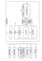
- FIG. 14 is a block diagram showing an example of the information processing device 5 according to the first embodiment.
- FIG. 15 is a functional explanatory diagram showing an example of the information processing device 5 according to the first embodiment.
- the information processing device 5 includes a control unit 50 , a communication unit 51 and a trained model storage unit 52 .
- the control unit 50 functions as an information acquisition unit 500 , a state prediction unit 501 and an output processing unit 502 .
- the communication unit 51 is connected to an external device (for example, the substrate processing device 2, the database device 3, the machine learning device 4, the user terminal device 6, etc.) via the network 7, and serves as a communication interface for transmitting and receiving various data. Function.
- the information acquisition unit 500 is connected to an external device via the communication unit 51 and the network 7, and acquires operating state information including substrate rotation state information, substrate holding position information, and substrate pressing load information.
- the information acquisition unit 500 refers to the finishing history table 301 of the production history information 30.
- the substrate rotation state information, the substrate holding position information, and the substrate pressing load information when the finishing process is performed on the wafer W are acquired as operation state information.
- the information acquiring unit 500 receives the information from the substrate processing apparatus 2 that is performing the finishing process.
- the substrate rotation status information, the substrate holding position information, and the substrate pressing load information while the wafer W is being finished are used as the operation status information. Obtain at any time.
- the information acquisition unit 500 obtains the substrate recipe information 266 from the substrate processing apparatus 2 scheduled to perform the finish processing. and simulates the apparatus state information when the substrate processing apparatus 2 operates according to the substrate recipe conditions 266, thereby obtaining substrate rotation state information and substrate holding position information when finishing processing is performed on the wafer W. , and substrate pressing load information as operation state information.
- the state prediction unit 501 By inputting the operation state information acquired by the information acquisition unit 500 as input data to the first learning model 10A as described above, the state prediction unit 501 performs substrate processing in the operation state indicated by the operation state information. Substrate holding mechanism portion state information indicating the states of the substrate holding mechanism portions 241a, 241c, and 241e when the apparatus 2 operates is predicted.
- the learned model storage unit 52 is a database that stores the learned first learning model 10A used in the state prediction unit 501.
- the number of first learning models 10A stored in the learned model storage unit 52 is not limited to one.
- a plurality of trained models with different conditions, such as differences in mechanisms, types of data included in the operating state information, types of data included in the state information of the substrate holding mechanism, etc., may be stored and selectively used. good.
- the trained model storage unit 52 may be replaced by a storage unit of an external computer (for example, a server computer or a cloud computer), in which case the state prediction unit 501 may access the external computer. .
- the output processing unit 502 performs output processing for outputting the substrate holding mechanism unit state information generated by the state prediction unit 501 .
- the output processing unit 502 may transmit the substrate holding mechanism state information to the user terminal device 6 so that a display screen based on the substrate holding mechanism state information may be displayed on the user terminal device 6,
- the substrate holding mechanism state information may be registered in the production history information 30 by transmitting the substrate holding mechanism state information to the database device 3 .
- FIG. 16 is a flowchart showing an example of an information processing method by the information processing device 5. As shown in FIG. An operation example in which the user operates the user terminal device 6 to perform "post-prediction processing" of the substrate holding mechanism state information for a specific wafer W will be described below.
- step S200 when the user performs an input operation for inputting a wafer ID specifying a wafer W to be predicted to the user terminal device 6, the user terminal device 6 sends the wafer ID to the information processing device 5. Send to
- step S210 the information acquisition unit 500 of the information processing device 5 receives the wafer ID transmitted in step S200.
- the information acquisition unit 500 refers to the finishing history table 301 of the production history information 30 using the wafer ID received in step S210, so that the wafer W specified by the wafer ID is finished. Get the operation state information when it was done.
- step S220 the state prediction unit 501 inputs the operation state information acquired in step S211 as input data to the first learning model 10A, thereby obtaining board holding mechanism state information corresponding to the operation state information. are generated as output data, and the states of the substrate holding mechanisms 241a, 241c, and 241e are predicted.
- step S230 the output processing unit 502 transmits the substrate holding mechanism state information to the user terminal device 6 as output processing for outputting the substrate holding mechanism state information generated in step S220.
- the destination of the substrate holding mechanism state information may be the database device 3 in addition to or instead of the user terminal device 6 .
- step S240 upon receiving the substrate holding mechanism state information transmitted in step S230 as a response to the transmission processing in step S200, the user terminal device 6 displays a display based on the substrate holding mechanism state information. By displaying the screen, the user can visually recognize the states of the substrate holding mechanisms 241a, 241c, and 241e.
- steps S210 and S211 correspond to the information acquisition step
- step S220 corresponds to the state prediction step
- step S230 corresponds to the output processing step.
- the operation state information including the substrate rotation state information, the substrate holding position information, and the substrate pressing load information in the finishing process is set to the first position.
- the learning model 10A the substrate holding mechanism portion state information corresponding to the operating state information is predicted. can be reasonably predicted.
- the second embodiment differs from the first embodiment in that the substrate holding mechanism state information is remaining life information indicating the remaining life of the substrate holding mechanisms 241a, 241c, and 241e.
- the machine learning device 4a and the information processing device 5a according to the second embodiment will be described, focusing on the differences from the first embodiment.
- FIG. 17 is a block diagram showing an example of a machine learning device 4a according to the second embodiment.
- FIG. 18 is a diagram showing an example of the second learning model 10B and the second learning data 11B.
- the second learning data 11B is used for machine learning of the second learning model 10B.
- the substrate holding mechanism state information constituting the second learning data 11B is remaining life information indicating the remaining life of the substrate holding mechanism portions 241a, 241c, and 241e.
- the remaining lives of the substrate holding mechanism portions 241a, 241c, and 241e are determined, for example, by the number of usable times and the usable time until the substrate holding mechanism portions 241a, 241c, and 241e reach the end of their lives.
- the operating state information that constitutes the second learning data 11B is the same as in the first embodiment, so description thereof will be omitted.
- the learning data acquisition unit 400 acquires the second learning data 11B by referring to the finishing test information 31 and accepting user input operations through the user terminal device 6 as necessary.
- the finishing test information 31 for example, when the substrate holding mechanism parts for testing are used to repeatedly perform the finishing process as a finishing test, the life span of the substrate holding mechanism parts 241a, 241c, and 241e is reached. In the life information, "0" is set, and test result information in which a larger value is set as it goes back in the past is registered. Then, the learning data acquisition unit 400 acquires remaining life information by acquiring test result information when the finishing test specified by the test ID is performed from the finishing test table 310 of the finishing test information 31 .
- the machine learning unit 401 inputs a plurality of sets of the second learning data 11B to the second learning model 10B, and obtains the operation state information and substrate holding mechanism state information (remaining life information) included in the second learning data 11B. ) is learned by the second learning model 10B, a learned second learning model 10B is generated.
- FIG. 19 is a block diagram showing an example of an information processing device 5a functioning as the information processing device 5a according to the second embodiment.
- FIG. 20 is a functional explanatory diagram showing an example of the information processing device 5a according to the second embodiment.
- the information acquisition unit 500 acquires operating state information including substrate rotation state information, substrate holding position information, and substrate pressing load information, as in the first embodiment.
- the state prediction unit 501 inputs the operation state information acquired by the information acquisition unit 500 as input data to the second learning model 10B as described above, thereby performing substrate processing in the operation state indicated by the operation state information.
- Substrate holding mechanism state information (remaining life information) indicating the states of the substrate holding mechanisms 241a, 241c, and 241e when the apparatus 2 operates is predicted.
- the operation state information including the substrate rotation state information, the substrate holding position information, and the substrate pressing load information in the finishing process is set to the second position.
- the learning model 10B substrate holding mechanism portion state information (remaining life information) corresponding to the operating state information is predicted.
- 241e can be reasonably predicted.
- the database device 3, the machine learning device 4, and the information processing device 5 are described as being composed of separate devices, but these three devices may be composed of a single device. However, any two of the three devices may be configured as a single device. At least one of the machine learning device 4 and the information processing device 5 may be incorporated in the control unit 26 of the substrate processing apparatus 2 or the user terminal device 6 .
- the substrate processing apparatus 2 has been described as having the respective units 21 to 25, but the substrate processing apparatus 2 has a function of holding the wafer W when cleaning the finishing unit 24 and a drying process. At least one of the functions of holding the wafer W during the operation may be provided, and the other units may be omitted.
- machine learning models include, for example, tree types such as decision trees and regression trees, ensemble learning such as bagging and boosting, recurrent neural networks, convolutional neural networks, and neural network types such as LSTM (including deep learning ), hierarchical clustering, non-hierarchical clustering, k-nearest neighbor method, k-means method and other clustering types, principal component analysis, factor analysis, logistic regression and other multivariate analyzes, and support vector machines.
- the test result information is information indicating the state of the substrate holding mechanism portions when the finishing process is performed in the finishing test using the dummy wafer in the testing apparatus.
- the information may be continuously acquired as information indicating the state when the actual finishing processing of the wafer W is performed using the actual finishing unit 24 in which the sensor for detecting the state is installed.
- the continuously acquired test result information is continuously learned by the machine learning device 4 .
- the test result information is obtained by determining the degree of contamination, wear, or damage of the substrate holding mechanism portions 241a, 241c, and 241e, labeling the data, and continuing. It may be made to be obtained on a specific basis.
- information continuously acquired using the actual finishing unit 24 may be uploaded to the cloud, machine-learned in the cloud, and then the learned model may be deployed to the substrate processing apparatus 2 .
- the processing method may be learned within the substrate processing apparatus 2 without uploading to the cloud.
- the present invention is provided in the form of a program (machine learning program) that causes the computer 900 to function as each part of the machine learning device 4, and a program (machine learning program) that causes the computer 900 to execute each step of the machine learning method.
- a program information processing program
- the present invention provides a program (information processing program) for causing the computer 900 to function as each unit provided in the information processing apparatus 5, and a program for causing the computer 900 to execute each step provided in the information processing method according to the above embodiment. It can also be provided in the form of (information processing program).
- the present invention can be applied not only to the aspect of the information processing device 5 (information processing method or information processing program) according to the above-described embodiment, but also to an inference device (inference method or inference method) used to infer substrate holding mechanism state information. program).
- the inference device may include a memory and a processor, and the processor of these may execute a series of processes.
- the series of processes includes an information acquisition process (information acquisition step) for acquiring operation state information, and when the operation state information is acquired in the information acquisition process, the substrate processing apparatus 2 is operated in the operation state indicated by the operation state information.
- Inference processing for inferring substrate holding mechanism state information (condition information or remaining life information) indicating the state of the substrate holding mechanism when operated.
- the state prediction unit uses the learned learning model generated by the machine learning device 4 and the machine learning method according to the above embodiment. It should be understood by those skilled in the art that the reasoning techniques implemented by 501 may also be applied.
- the present invention can be used for information processing devices, inference devices, machine learning devices, information processing methods, inference methods, and machine learning methods.
- SYMBOLS 1 Substrate processing system, 2... Substrate processing apparatus, 3... Database apparatus, 4, 4a... machine learning device, 5, 5a... information processing device, 6... User terminal device, 7... Network, 10A... first learning model, 10B... second learning model, 11A... First learning data, 11B... Second learning data, 20... housing, 21... load/unload unit, 22... Polishing unit, 22A to 22D... Polishing part, 23... Substrate transfer unit, 24... Finishing unit, 24A, 24B... Roll sponge cleaning part, 24C, 24D... pen sponge washing section, 24E, 24F... drying section, 24G, 24H... transport unit, 25... film thickness measurement unit, 26...
- control unit 30...Production history information, 31...Finishing test information, 40... control unit, 41... communication unit, 42... learning data storage unit, 43 ... learned model storage unit, 50... Control unit, 51... Communication unit, 52... Learned model storage unit, 220... polishing table, 221... top ring, 222... liquid supply nozzle, 223...dresser, 224...atomizer, 240... Substrate cleaning part, 241... Substrate holding part, 242... Cleaning fluid supply part, 243...Cleaning tool cleaning unit, 244...Environment sensor, 245...Dry fluid supply unit, 260... control unit, 21... communication unit, 262... input unit, 263... output unit, 264... storage unit, 300 ...
- Wafer history table 301 ... Finishing history table, 310 ... Finishing test table, 400... Learning data acquisition unit, 401... Machine learning unit, 500... Information acquisition unit, 501... State prediction unit, 502... Output processing unit, 900... computer, 2200 Polishing pad 2230 Dresser disk 2400 Roll sponge 2401... Pen sponge
Landscapes
- Engineering & Computer Science (AREA)
- Mechanical Engineering (AREA)
- Theoretical Computer Science (AREA)
- Software Systems (AREA)
- Evolutionary Computation (AREA)
- Mathematical Physics (AREA)
- Data Mining & Analysis (AREA)
- Physics & Mathematics (AREA)
- Computing Systems (AREA)
- General Engineering & Computer Science (AREA)
- General Physics & Mathematics (AREA)
- Medical Informatics (AREA)
- Computer Vision & Pattern Recognition (AREA)
- Artificial Intelligence (AREA)
- Cleaning Or Drying Semiconductors (AREA)
- Finish Polishing, Edge Sharpening, And Grinding By Specific Grinding Devices (AREA)
- Mechanical Treatment Of Semiconductor (AREA)
- Constituent Portions Of Griding Lathes, Driving, Sensing And Control (AREA)
- General Factory Administration (AREA)
Abstract
Description
基板を保持する基板保持機構部及び基板を回転させる基板回転機構部を有する基板保持部を備える基板処理装置が動作したときの動作状態として、前記基板の回転状態を示す基板回転状態情報、前記基板保持機構部の基板保持位置を示す基板保持位置情報、及び、前記基板保持機構部の基板押付荷重を示す基板押付荷重情報、を含む動作状態情報を取得する情報取得部と、
前記動作状態情報と、当該動作状態情報が示す前記動作状態にて前記基板処理装置が動作したときの前記基板保持機構部の状態を示す基板保持機構部状態情報との相関関係を機械学習により学習させた学習モデルに、前記情報取得部により取得された前記動作状態情報を入力することで、当該動作状態情報に対する前記基板保持機構部状態情報を予測する状態予測部と、
を備える。
図1は、基板処理システム1の一例を示す全体構成図である。本実施形態に係る基板処理システム1は、半導体ウェハ等の基板(以下、「ウェハ」という)Wを研磨パッドに押し付けることでウェハWの表面を平坦に研磨する化学機械研磨処理(以下、「研磨処理」という)、研磨処理後のウェハWを洗浄具に接触させることでウェハWの表面を洗浄する洗浄処理、洗浄したウェハWの表面を乾燥具により乾燥する乾燥処理等を含む一連の基板処理を管理するシステムとして機能する。なお、洗浄処理と乾燥処理は、仕上げ処理を構成し、洗浄具と乾燥具は、仕上げ具に含まれる。
図2は、基板処理装置2の一例を示す平面図である。基板処理装置2は、平面視で略矩形状のハウジング20の内部に、ロード/アンロードユニット21と、研磨ユニット22と、基板搬送ユニット23と、仕上げユニット24と、膜厚測定ユニット25と、制御ユニット26とを備えて構成される。ロード/アンロードユニット21と、研磨ユニット22、基板搬送ユニット23及び仕上げユニット24との間は、第1の隔壁200Aにより区画され、基板搬送ユニット23と仕上げユニット24との間は、第2の隔壁200Bにより区画されている。
ロード/アンロードユニット21は、多数のウェハWを上下方向に収納可能なウェハカセット(FOUP等)が載置される第1乃至第4のフロントロード部210A~210Dと、ウェハカセットに収納されたウェハWの収納方向(上下方向)に沿って上下移動可能な搬送ロボット211と、第1乃至第4のフロントロード部210A~210Dの並び方向(ハウジング20の短手方向)に沿って搬送ロボット211を移動させる水平移動機構部212とを備える。
研磨ユニット22は、ウェハWの研磨処理(平坦化)をそれぞれ行う第1乃至第4の研磨部22A~22Dを備える。第1乃至第4の研磨部22A~22Dは、ハウジング20の長手方向に沿って並べられて配置される。
基板搬送ユニット23は、図2に示すように、第1乃至第4の研磨部22A~22Dの並び方向(ハウジング20の長手方向)に沿って水平移動可能な第1及び第2のリニアトランスポータ230A、230Bと、第1及び第2のリニアトランスポータ230A、230Bの間に配置されたスイングトランスポータ231と、ロード/アンロードユニット21側に配置されたリフタ232と、仕上げユニット24側に配置されたウェハWの仮置き台233とを備える。
仕上げユニット24は、図2に示すように、ロールスポンジ2400を用いた基板洗浄装置として、上下二段に配置された第1及び第2のロールスポンジ洗浄部24A、24Bと、ペンスポンジ2401を用いた基板洗浄装置として、上下二段に配置された第1及び第2のペンスポンジ洗浄部24C、24Dと、洗浄後のウェハWを乾燥させる基板乾燥装置として、上下二段に配置された第1及び第2の乾燥部24E、24Fと、ウェハWを搬送する第1及び第2の搬送部24G、24Hとを備える。なお、ロールスポンジ洗浄部24A、24B、ペンスポンジ洗浄部24C、24D、乾燥部24E、24F、及び、搬送部24G、24Hの数や配置は、図2の例に限られず、適宜変更してもよい。
膜厚測定ユニット25は、研磨処理前又は研磨処理後のウェハWの膜厚を測定する測定器であり、例えば、光学式膜厚測定器、渦電流式膜厚測定器等で構成される。各膜厚測定モジュールに対するウェハWの受け渡しは、搬送ロボット211により行われる。
図7は、基板処理装置2の一例を示すブロック図である。制御ユニット26は、各ユニット21~25と電気的に接続されて、各ユニット21~25を統括的に制御する制御部として機能する。以下では、仕上げユニット24の制御系(モジュール、センサ、シーケンサ)を例にして説明するが、他のユニット21~23、25も基本的な構成や機能は共通するため、説明を省略する。
図8は、コンピュータ900の一例を示すハードウエア構成図である。基板処理装置2の制御ユニット26、データベース装置3、機械学習装置4、情報処理装置5、及び、ユーザ端末装置6の各々は、汎用又は専用のコンピュータ900により構成される。
図9は、データベース装置3により管理される生産履歴情報30の一例を示すデータ構成図である。生産履歴情報30は、本生産用の基板処理が行われたときに取得されたレポートRが分類されて登録されるテーブルとして、例えば、各ウェハWに関するウェハ履歴テーブル300と、仕上げ処理における装置状態情報に関する仕上げ履歴テーブル301とを備える。なお、仕上げ履歴テーブル301は、洗浄処理における装置状態情報に関する洗浄履歴テーブル及び乾燥処理における装置状態情報に関する乾燥履歴デーブルを含む。また、生産履歴情報30は、上記の他に、研磨処理における装置状態情報に関する研磨履歴テーブル、イベント情報に関するイベント履歴テーブル及び操作情報に関する操作履歴テーブル等を備えるが、詳細な説明は省略する。
図10は、データベース装置3により管理される仕上げ試験情報31の一例を示すデータ構成図である。仕上げ試験情報31は、試験用の基板保持部や仕上げ試験装置を用いて仕上げ試験が行われたときに取得されたレポートR及び試験結果が分類されて登録される仕上げ試験テーブル310を備える。
図11は、第1の実施形態に係る機械学習装置4の一例を示すブロック図である。機械学習装置4は、制御部40、通信部41、学習用データ記憶部42、及び、学習済みモデル記憶部43を備える。
図13は、機械学習装置4による機械学習方法の一例を示すフローチャートである。
図14は、第1の実施形態に係る情報処理装置5の一例を示すブロック図である。図15は、第1の実施形態に係る情報処理装置5の一例を示す機能説明図である。情報処理装置5は、制御部50、通信部51、及び、学習済みモデル記憶部52を備える。
図16は、情報処理装置5による情報処理方法の一例を示すフローチャートである。以下では、ユーザがユーザ端末装置6を操作して、特定のウェハWに対する基板保持機構部状態情報の「事後予測処理」を行う場合の動作例について説明する。
第2の実施形態は、基板保持機構部状態情報が、基板保持機構部241a、241c、241eの余寿命を示す余寿命情報である点で第1の実施形態と相違する。以下では、第2の実施形態に係る機械学習装置4a及び情報処理装置5aについて、第1の実施形態と異なる部分を中心に説明する。
本発明は上述した実施形態に制約されるものではなく、本発明の主旨を逸脱しない範囲内で種々変更して実施することが可能である。そして、それらはすべて、本発明の技術思想に含まれるものである。
本発明は、機械学習装置4が備える各部としてコンピュータ900を機能させるプログラム(機械学習プログラム)や、機械学習方法が備える各工程をコンピュータ900に実行させるためのプログラム(機械学習プログラム)の態様で提供することもできる。また、本発明は、情報処理装置5が備える各部としてコンピュータ900を機能させるためのプログラム(情報処理プログラム)や、上記実施形態に係る情報処理方法が備える各工程をコンピュータ900に実行させるためのプログラム(情報処理プログラム)の態様で提供することもできる。
本発明は、上記実施形態に係る情報処理装置5(情報処理方法又は情報処理プログラム)の態様によるもののみならず、基板保持機構部状態情報を推論するために用いられる推論装置(推論方法又は推論プログラム)の態様で提供することもできる。その場合、推論装置(推論方法又は推論プログラム)としては、メモリと、プロセッサとを含み、このうちのプロセッサが、一連の処理を実行するものとすることができる。当該一連の処理とは、動作状態情報を取得する情報取得処理(情報取得工程)と、情報取得処理にて動作状態情報を取得すると、当該動作状態情報が示す動作状態にて基板処理装置2が動作したときの基板保持機構部の状態を示す基板保持機構部状態情報(コンディション情報又は余寿命情報)を推論する推論処理(推論工程)とを含む。
4、4a…機械学習装置、5、5a…情報処理装置、
6…ユーザ端末装置、7…ネットワーク、
10A…第1の学習モデル、10B…第2の学習モデル、
11A…第1の学習用データ、11B…第2の学習用データ、
20…ハウジング、21…ロード/アンロードユニット、
22…研磨ユニット、22A~22D…研磨部、23…基板搬送ユニット、
24…仕上げユニット、24A、24B…ロールスポンジ洗浄部、
24C、24D…ペンスポンジ洗浄部、24E、24F…乾燥部、
24G、24H…搬送部、25…膜厚測定ユニット、26…制御ユニット、
30…生産履歴情報、31…仕上げ試験情報、
40…制御部、41…通信部、42…学習用データ記憶部、
43…学習済みモデル記憶部、
50…制御部、51…通信部、52…学習済みモデル記憶部、
220…研磨テーブル、221…トップリング、222…液体供給ノズル、
223…ドレッサ、224…アトマイザ、
240…基板洗浄部、241…基板保持部、242…洗浄流体供給部、
243…洗浄具洗浄部、244…環境センサ、245…乾燥流体供給部、
260…制御部、21…通信部、262…入力部、263…出力部、264…記憶部、
300…ウェハ履歴テーブル、301…仕上げ履歴テーブル、310…仕上げ試験テーブル、
400…学習用データ取得部、401…機械学習部、
500…情報取得部、501…状態予測部、502…出力処理部、
900…コンピュータ、
2200…研磨パッド、2230…ドレッサディスク、2400…ロールスポンジ、
2401…ペンスポンジ
Claims (12)
- 基板を保持する基板保持機構部及び基板を回転させる基板回転機構部を有する基板保持部を備える基板処理装置が動作したときの動作状態として、前記基板の回転状態を示す基板回転状態情報、前記基板保持部の基板保持位置を示す基板保持位置情報、及び、前記基板保持部の基板押付荷重を示す基板押付荷重情報、を含む動作状態情報を取得する情報取得部と、
前記動作状態情報と、当該動作状態情報が示す前記動作状態にて前記基板処理装置が動作したときの前記基板保持機構部の状態を示す基板保持機構部状態情報との相関関係を機械学習により学習させた学習モデルに、前記情報取得部により取得された前記動作状態情報を入力することで、当該動作状態情報に対する前記基板保持機構部状態情報を予測する状態予測部と、
を備える、
情報処理装置。 - 前記基板回転状態情報は、
前記基板の回転速度を示す基板回転速度情報、及び、
前記基板の回転トルクを示す基板回転トルク情報、の少なくとも1つを含む、
請求項1に記載の情報処理装置。 - 前記動作状態情報に含まれる前記基板回転速度情報は、
前記基板の回転数、
前記基板に形成された被計測部のカウント数、及び、
前記基板回転機構部の回転数、の少なくとも1つを含む、
請求項2に記載の情報処理装置。 - 前記動作状態情報に含まれる前記基板回転トルク情報は、
前記基板回転機構部の回転トルクを含む、
請求項2又は請求項3に記載の情報処理装置。 - 前記動作状態情報に含まれる前記基板保持位置情報は、
前記基板保持機構部が前記基板を保持する保持位置を含む、
請求項1乃至請求項4のいずれか一項に記載の情報処理装置。 - 前記基板保持機構部状態情報は、
前記基板保持機構部の汚染度情報、
前記基板保持機構部の摩耗度情報、及び、
前記基板保持機構部の破損度情報、の少なくとも1つを含む、
請求項1乃至請求項5のいずれか一項に記載の情報処理装置。 - 前記基板保持機構部状態情報は、前記基板保持機構部の余寿命情報を含む、
請求項1乃至請求項5のいずれか一項に記載の情報処理装置。 - メモリと、プロセッサとを備える推論装置であって、
前記プロセッサは、
基板を保持する基板保持機構部及び基板を回転させる基板回転機構部を有する基板保持部を備える基板処理装置が動作したときの動作状態として、
前記基板の回転状態を示す基板回転状態情報、前記基板保持機構部の基板保持位置を示す基板保持位置情報、及び、前記基板保持機構部の基板押付荷重を示す基板押付荷重情報、を含む動作状態情報を取得する情報取得処理と、
前記情報取得処理にて前記動作状態情報を取得すると、当該動作状態情報が示す前記動作状態にて前記基板処理装置が動作したときの前記基板保持機構部の状態を示す基板保持機構部状態情報を推論する推論処理と、
を実行する、
推論装置。 - 基板を保持する基板保持機構部及び基板を回転させる基板回転機構部を有する基板保持部を備える基板処理装置が動作したときの動作状態として、前記基板の回転状態を示す基板回転状態情報、前記基板保持機構部の基板保持位置を示す基板保持位置情報、及び、前記基板保持機構部の基板押付荷重を示す基板押付荷重情報、を含む動作状態情報と、当該動作状態情報が示す前記動作状態にて前記基板処理装置が動作したときの前記基板保持機構部の状態を示す基板保持機構部状態情報とで構成される学習用データを複数組記憶する学習用データ記憶部と、
複数組の前記学習用データを学習モデルに入力することで、前記動作状態情報と前記基板保持機構部状態情報との相関関係を前記学習モデルに学習させる機械学習部と、
前記機械学習部により前記相関関係を学習させた前記学習モデルを記憶する学習済みモデル記憶部と、
を備える、
機械学習装置。 - 基板を保持する基板保持機構部及び基板を回転させる基板回転機構部を有する基板保持部を備える基板処理装置が動作したときの動作状態として、前記基板の回転状態を示す基板回転状態情報、前記基板保持機構部の基板保持位置を示す基板保持位置情報、及び、前記基板保持機構部の基板押付荷重を示す基板押付荷重情報を含む動作状態情報を取得する情報取得工程と、
前記動作状態情報と、当該動作状態情報が示す前記動作状態にて前記基板処理装置が動作したときの前記基板保持機構部状態情報との相関関係を機械学習により学習させた学習モデルに、前記情報取得工程により取得された前記動作状態情報を入力することで、当該動作状態情報に対する前記基板保持機構部状態情報を予測する状態予測工程と、
を備える、
情報処理方法。 - メモリと、プロセッサとを備える推論装置により実行される推論方法であって、
前記プロセッサは、
基板を保持する基板保持機構部及び基板を回転させる基板回転機構部を有する基板保持部を備える基板処理装置が動作したときの動作状態として、前記基板の回転状態を示す基板回転状態情報、前記基板保持機構部の基板保持位置を示す基板保持位置情報、及び、前記基板保持機構部の基板押付荷重を示す基板押付荷重情報を含む動作状態情報を取得する情報取得工程と、
前記情報取得工程にて前記動作状態情報を取得すると、当該動作状態情報が示す前記動作状態にて前記基板処理装置が動作したときの前記基板保持機構部の状態を示す基板保持機構部状態情報を推論する推論工程と、
を実行する、
推論方法。 - 基板を保持する基板保持機構部及び基板を回転させる基板回転機構部を有する基板保持部を備える基板処理装置が動作したときの動作状態として、前記基板の回転状態を示す基板回転状態情報、前記基板保持機構部の基板保持位置を示す基板保持位置情報、及び、前記基板保持機構部の基板押付荷重を示す基板押付荷重情報を含む動作状態情報と、当該動作状態情報が示す前記動作状態にて前記基板処理装置が動作したときの前記基板保持機構部の状態を示す基板保持機構部状態情報とで構成される学習用データを学習用データ記憶部に複数組記憶する学習用データ記憶工程と、
複数組の前記学習用データを学習モデルに入力することで、前記動作状態情報と前記基板保持機構部状態情報との相関関係を前記学習モデルに学習させる機械学習工程と、
前記機械学習工程により前記相関関係を学習させた前記学習モデルを学習済みモデル記憶部に記憶する学習済みモデル記憶工程と、
を備える、
機械学習方法。
Priority Applications (3)
| Application Number | Priority Date | Filing Date | Title |
|---|---|---|---|
| KR1020247029114A KR20240147989A (ko) | 2022-02-04 | 2023-01-11 | 정보 처리 장치, 추론 장치, 기계 학습 장치, 정보 처리 방법, 추론 방법, 및 기계 학습 방법 |
| US18/834,710 US20250125172A1 (en) | 2022-02-04 | 2023-01-11 | Information processing apparatus, inference apparatus, machine-learning apparatus, information processing method, inference method, and machine-learning method |
| CN202380019756.8A CN118661244A (zh) | 2022-02-04 | 2023-01-11 | 信息处理装置、推论装置、机器学习装置、信息处理方法、推论方法及机器学习方法 |
Applications Claiming Priority (2)
| Application Number | Priority Date | Filing Date | Title |
|---|---|---|---|
| JP2022-016283 | 2022-02-04 | ||
| JP2022016283A JP7753124B2 (ja) | 2022-02-04 | 2022-02-04 | 情報処理装置、推論装置、機械学習装置、情報処理方法、推論方法、及び、機械学習方法 |
Publications (1)
| Publication Number | Publication Date |
|---|---|
| WO2023149161A1 true WO2023149161A1 (ja) | 2023-08-10 |
Family
ID=87551986
Family Applications (1)
| Application Number | Title | Priority Date | Filing Date |
|---|---|---|---|
| PCT/JP2023/000371 Ceased WO2023149161A1 (ja) | 2022-02-04 | 2023-01-11 | 情報処理装置、推論装置、機械学習装置、情報処理方法、推論方法、及び、機械学習方法 |
Country Status (6)
| Country | Link |
|---|---|
| US (1) | US20250125172A1 (ja) |
| JP (1) | JP7753124B2 (ja) |
| KR (1) | KR20240147989A (ja) |
| CN (1) | CN118661244A (ja) |
| TW (1) | TW202347475A (ja) |
| WO (1) | WO2023149161A1 (ja) |
Citations (8)
| Publication number | Priority date | Publication date | Assignee | Title |
|---|---|---|---|---|
| JP2006004992A (ja) * | 2004-06-15 | 2006-01-05 | Seiko Epson Corp | 研磨装置管理システム、管理装置、管理装置制御プログラム及び管理装置制御方法 |
| JP2007294920A (ja) * | 2006-03-31 | 2007-11-08 | Ebara Corp | 基板保持回転機構、基板処理装置 |
| US20190162675A1 (en) * | 2017-11-28 | 2019-05-30 | Taiwan Semiconductor Manufacturing Co., Ltd. | Apparatus and method for inspecting a wafer process chamber |
| JP2020061469A (ja) * | 2018-10-10 | 2020-04-16 | 株式会社荏原製作所 | 基板洗浄方法、基板洗浄装置、基板処理装置、基板処理システム、および機械学習器 |
| JP2020109839A (ja) * | 2018-12-28 | 2020-07-16 | 株式会社荏原製作所 | パッド温度調整装置、パッド温度調整方法、研磨装置、および研磨システム |
| WO2021117685A1 (ja) * | 2019-12-13 | 2021-06-17 | 株式会社荏原製作所 | 基板洗浄装置、研磨装置、バフ処理装置、基板洗浄方法、基板処理装置、および機械学習器 |
| JP2021132140A (ja) * | 2020-02-20 | 2021-09-09 | 東京エレクトロン株式会社 | 情報処理システム及びシミュレーション方法 |
| JP2021152762A (ja) * | 2020-03-24 | 2021-09-30 | 株式会社Screenホールディングス | 学習済みモデル生成方法、学習済みモデル、異常要因推定装置、基板処理装置、異常要因推定方法、学習方法、学習装置、及び、学習データ作成方法 |
Family Cites Families (1)
| Publication number | Priority date | Publication date | Assignee | Title |
|---|---|---|---|---|
| JP6435036B2 (ja) | 2017-11-09 | 2018-12-05 | 株式会社荏原製作所 | 回転保持装置及び基板洗浄装置 |
-
2022
- 2022-02-04 JP JP2022016283A patent/JP7753124B2/ja active Active
-
2023
- 2023-01-11 KR KR1020247029114A patent/KR20240147989A/ko active Pending
- 2023-01-11 WO PCT/JP2023/000371 patent/WO2023149161A1/ja not_active Ceased
- 2023-01-11 US US18/834,710 patent/US20250125172A1/en active Pending
- 2023-01-11 CN CN202380019756.8A patent/CN118661244A/zh active Pending
- 2023-01-17 TW TW112101915A patent/TW202347475A/zh unknown
Patent Citations (8)
| Publication number | Priority date | Publication date | Assignee | Title |
|---|---|---|---|---|
| JP2006004992A (ja) * | 2004-06-15 | 2006-01-05 | Seiko Epson Corp | 研磨装置管理システム、管理装置、管理装置制御プログラム及び管理装置制御方法 |
| JP2007294920A (ja) * | 2006-03-31 | 2007-11-08 | Ebara Corp | 基板保持回転機構、基板処理装置 |
| US20190162675A1 (en) * | 2017-11-28 | 2019-05-30 | Taiwan Semiconductor Manufacturing Co., Ltd. | Apparatus and method for inspecting a wafer process chamber |
| JP2020061469A (ja) * | 2018-10-10 | 2020-04-16 | 株式会社荏原製作所 | 基板洗浄方法、基板洗浄装置、基板処理装置、基板処理システム、および機械学習器 |
| JP2020109839A (ja) * | 2018-12-28 | 2020-07-16 | 株式会社荏原製作所 | パッド温度調整装置、パッド温度調整方法、研磨装置、および研磨システム |
| WO2021117685A1 (ja) * | 2019-12-13 | 2021-06-17 | 株式会社荏原製作所 | 基板洗浄装置、研磨装置、バフ処理装置、基板洗浄方法、基板処理装置、および機械学習器 |
| JP2021132140A (ja) * | 2020-02-20 | 2021-09-09 | 東京エレクトロン株式会社 | 情報処理システム及びシミュレーション方法 |
| JP2021152762A (ja) * | 2020-03-24 | 2021-09-30 | 株式会社Screenホールディングス | 学習済みモデル生成方法、学習済みモデル、異常要因推定装置、基板処理装置、異常要因推定方法、学習方法、学習装置、及び、学習データ作成方法 |
Also Published As
| Publication number | Publication date |
|---|---|
| KR20240147989A (ko) | 2024-10-10 |
| US20250125172A1 (en) | 2025-04-17 |
| TW202347475A (zh) | 2023-12-01 |
| CN118661244A (zh) | 2024-09-17 |
| JP7753124B2 (ja) | 2025-10-14 |
| JP2023114126A (ja) | 2023-08-17 |
Similar Documents
| Publication | Publication Date | Title |
|---|---|---|
| WO2023189170A1 (ja) | 情報処理装置、推論装置、機械学習装置、情報処理方法、推論方法、及び、機械学習方法 | |
| WO2023149162A1 (ja) | 情報処理装置、推論装置、機械学習装置、情報処理方法、推論方法、及び、機械学習方法 | |
| WO2023166991A1 (ja) | 情報処理装置、推論装置、機械学習装置、情報処理方法、推論方法、及び、機械学習方法 | |
| WO2023112830A1 (ja) | 情報処理装置、推論装置、機械学習装置、情報処理方法、推論方法、及び、機械学習方法 | |
| JP2023116396A (ja) | 情報処理装置、推論装置、機械学習装置、情報処理方法、推論方法、及び、機械学習方法 | |
| WO2023189165A1 (ja) | 情報処理装置、推論装置、機械学習装置、情報処理方法、推論方法、及び、機械学習方法 | |
| WO2023149161A1 (ja) | 情報処理装置、推論装置、機械学習装置、情報処理方法、推論方法、及び、機械学習方法 | |
| WO2024024391A1 (ja) | 情報処理装置、機械学習装置、情報処理方法、及び、機械学習方法 | |
| CN118434534A (zh) | 信息处理装置、推论装置、机器学习装置、信息处理方法、推论方法及机器学习方法 | |
| WO2023153208A1 (ja) | 情報処理装置、推論装置、機械学習装置、情報処理方法、推論方法、及び、機械学習方法 | |
| JP2023090667A (ja) | 情報処理装置、推論装置、機械学習装置、情報処理方法、推論方法、及び、機械学習方法 | |
| WO2023058285A1 (ja) | 情報処理装置、推論装置、機械学習装置、情報処理方法、推論方法、及び、機械学習方法 | |
| US20240363449A1 (en) | Information processing device, inference device, and machine learning device | |
| JP2024038618A (ja) | 情報処理装置、機械学習装置、情報処理方法、及び、機械学習方法 | |
| CN118660786A (zh) | 信息处理装置、推论装置、机器学习装置、信息处理方法、推论方法及机器学习方法 |
Legal Events
| Date | Code | Title | Description |
|---|---|---|---|
| 121 | Ep: the epo has been informed by wipo that ep was designated in this application |
Ref document number: 23749478 Country of ref document: EP Kind code of ref document: A1 |
|
| WWE | Wipo information: entry into national phase |
Ref document number: 18834710 Country of ref document: US Ref document number: 202380019756.8 Country of ref document: CN |
|
| ENP | Entry into the national phase |
Ref document number: 20247029114 Country of ref document: KR Kind code of ref document: A |
|
| NENP | Non-entry into the national phase |
Ref country code: DE |
|
| WWE | Wipo information: entry into national phase |
Ref document number: 11202405201R Country of ref document: SG |
|
| 122 | Ep: pct application non-entry in european phase |
Ref document number: 23749478 Country of ref document: EP Kind code of ref document: A1 |
|
| WWP | Wipo information: published in national office |
Ref document number: 18834710 Country of ref document: US |