WO2023149113A1 - 弾性率算出方法及び弾性率算出装置 - Google Patents
弾性率算出方法及び弾性率算出装置 Download PDFInfo
- Publication number
- WO2023149113A1 WO2023149113A1 PCT/JP2022/047129 JP2022047129W WO2023149113A1 WO 2023149113 A1 WO2023149113 A1 WO 2023149113A1 JP 2022047129 W JP2022047129 W JP 2022047129W WO 2023149113 A1 WO2023149113 A1 WO 2023149113A1
- Authority
- WO
- WIPO (PCT)
- Prior art keywords
- grating
- subject
- diffraction grating
- ray
- section
- Prior art date
- Legal status (The legal status is an assumption and is not a legal conclusion. Google has not performed a legal analysis and makes no representation as to the accuracy of the status listed.)
- Ceased
Links
Images


Classifications
-
- G—PHYSICS
- G01—MEASURING; TESTING
- G01N—INVESTIGATING OR ANALYSING MATERIALS BY DETERMINING THEIR CHEMICAL OR PHYSICAL PROPERTIES
- G01N23/00—Investigating or analysing materials by the use of wave or particle radiation, e.g. X-rays or neutrons, not covered by groups G01N3/00 – G01N17/00, G01N21/00 or G01N22/00
- G01N23/02—Investigating or analysing materials by the use of wave or particle radiation, e.g. X-rays or neutrons, not covered by groups G01N3/00 – G01N17/00, G01N21/00 or G01N22/00 by transmitting the radiation through the material
- G01N23/04—Investigating or analysing materials by the use of wave or particle radiation, e.g. X-rays or neutrons, not covered by groups G01N3/00 – G01N17/00, G01N21/00 or G01N22/00 by transmitting the radiation through the material and forming images of the material
- G01N23/041—Phase-contrast imaging, e.g. using grating interferometers
Definitions
- the present invention relates to a technique for calculating the elastic modulus of a subject (that is, a sample).
- Elastography is known as a technique for noninvasively imaging the hardness distribution of viscoelastic bodies. Investigating the hardness distribution of living tissue can be useful for diagnosing cancer and arteriosclerosis and identifying the site.
- Elastography is roughly divided into static elastography (see, for example, Patent Document 1 below) and dynamic elastography (see, for example, Non-Patent Document 1 below).
- Static elastography finds the elastic modulus of a viscoelastic body based on the deformation caused by pressing on the body.
- static elastography it is necessary to construct a model of a viscoelastic body in order to estimate the elastic modulus from the amount of deformation, and it is difficult to construct an accurate model.
- Dynamic elastography vibrates a viscoelastic body, acquires the propagation velocity distribution of shear waves in the viscoelastic body as a displacement map, and obtains the elastic modulus (complex elastic modulus) of the viscoelastic body.
- MRI is used to acquire a displacement map.
- a technique for obtaining a displacement map using ultrasonic waves has also been proposed.
- techniques using MRI and ultrasound have the problem that the spatial resolution of the elastic modulus distribution is low. Poor spatial resolution can make it difficult to detect small lesions or blur the boundaries between lesion and normal regions. To facilitate diagnosis, a spatial resolution as high as possible is desired.
- Non-Patent Document 2 proposes a method (dynamic X-ray elastography) of obtaining a displacement map of a viscoelastic body using an X-ray projection image in Non-Patent Document 2 below. According to this method, since X-rays are used, spatial resolution higher than that of MRI and ultrasound can be expected.
- a method of obtaining an X-ray phase image by a fringe scanning method using a phase contrast X-ray optical system such as a Talbot interferometer is conceivable.
- a phase contrast X-ray optical system such as a Talbot interferometer
- it is necessary to move the grating for fringe scanning and there is a problem that the time required for imaging becomes long.
- the amount of exposure to X-rays may increase, and the possibility of the subject moving significantly during imaging also increases.
- a method of calculating the X-ray phase image from the X-ray projection image by the Fourier transform method without using the fringe scanning method is also conceivable, but there is a problem that the spatial resolution is lower than in the case of the fringe scanning method.
- the inventors of the present invention have found that the elasticity of a viscoelastic body can be measured with high spatial resolution by using a projection image in a phase-contrast X-ray optical system without using the fringe scanning method. It was found that the rate distribution can be obtained.
- a main object of the present invention is to provide a technique capable of calculating the elastic modulus of a viscoelastic body with high spatial resolution and relatively short measurement time.
- phase-contrast X-ray optical system uses a phase-contrast X-ray optical system that can detect the refraction or scattering of X-rays by the subject.
- the phase-contrast X-ray optical system includes a grating section, a radiation source for irradiating the grating section and the subject with X-rays, and detection for detecting the X-rays passing through the grating section and the subject for each pixel.
- the grating unit includes a first diffraction grating and a second diffraction grating arranged parallel to the self-image of the first diffraction grating, Further, a step of detecting the projection image of the X-ray by the detection unit while vibrating the subject while maintaining the relative positional relationship between the first diffraction grating and the second diffraction grating; and calculating the elastic modulus of the subject based on the amount of displacement of the wave caused by the vibration in the X-ray projection image detected by the detection unit.
- a phase-contrast X-ray optical system capable of detecting refraction or scattering of X-rays by a subject, a vibrating section for vibrating the subject, and a processing section
- the phase-contrast X-ray optical system includes a grating section, a radiation source for irradiating the grating section and the subject with X-rays, and detection for detecting the X-rays passing through the grating section and the subject for each pixel.
- the grating unit includes a first diffraction grating and a second diffraction grating arranged parallel to the self-image of the first diffraction grating, Further, a relative positional relationship between the first diffraction grating and the second diffraction grating is maintained,
- the vibration unit is configured to vibrate the subject in order to vibrate the subject,
- the processing unit is An elastic modulus calculation device configured to calculate an elastic modulus of the subject based on a displacement amount of waves caused by the vibration in the X-ray projection image detected by the detection unit.
- the elastic modulus of a viscoelastic body since a phase-contrast X-ray optical system is used, it is possible to calculate the elastic modulus of a viscoelastic body with high spatial resolution. Moreover, since the elastic modulus of the object is calculated using the X-ray projection image obtained by imaging the object while maintaining the relative positional relationship between the first diffraction grating and the second diffraction grating, fringe scanning is possible. Measurement time can be shortened compared to the case of implementing the method.
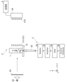
- FIG. 1 is an explanatory diagram showing a schematic configuration of an elastic modulus calculation device according to an embodiment of the present invention
- FIG. 2 is a block diagram for explaining the configuration of a processing unit in the apparatus of FIG. 1
- FIG. FIG. 2 is an explanatory diagram for explaining a procedure of an elastic modulus calculation method using the apparatus of FIG. 1
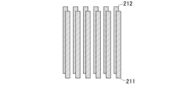
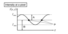
- FIG. 2 is an explanatory diagram for explaining the positional relationship of lattice members in the apparatus of FIG. 1; It is a graph for explaining the relationship between the amount of relative movement between the self-image of the G1 grating and the G2 grating and the received light intensity.
- FIG. 4A is a CT image of a sample (object) used in an example of the elastic modulus calculation method
- FIG. 2 is a diagram showing a displacement map in a coronal section when the sample is agarose with a concentration of 0.9%, where (a) shows longitudinal displacement and (b) shows transverse displacement.
- FIG. 2 is a diagram showing a displacement map in a coronal section when the sample is agarose with a concentration of 0.7%, where (a) shows displacement in the vertical direction and (b) shows displacement in the lateral direction.
- Fig. (a) is a storage modulus map calculated using the longitudinal displacement in the coronal cross section in the sample in Fig. 7, and Fig. (b) is the longitudinal displacement in the coronal cross section in the sample in Fig. 8.
- Fig. (a) is a storage modulus map calculated using the lateral displacement in the coronal cross section in the sample in Fig. 7, and Fig. (b) is the lateral displacement in the coronal cross section in the sample in Fig. 8. is a storage modulus map calculated using
- a subject 1 is a viscoelastic body through which vibration is propagated by excitation.
- the subject 1 is tissue of a living body.
- the tissue of the living body may be one that has been separated from the living body, or one that has not been separated as in the case of mammography, for example.
- the subject 1 may be an industrial product.
- the viscoelastic body includes a body having a low viscosity and a property close to that of an elastic body.
- the elastic modulus calculation apparatus (hereinafter sometimes simply referred to as "apparatus") of this embodiment includes a phase-contrast X-ray optical system 2 capable of detecting refraction or scattering of X-rays by a subject 1, and a It has a vibrating section 3 and a processing section 4 as a basic configuration.
- the phase-contrast X-ray optical system 2 includes a grating section 21, a radiation source 22 for irradiating the grating section 21 and the subject 1 with X-rays, a shutter (chopper) 23, a grating section 21, and the subject 1. and a detection unit 24 for detecting X-rays for each pixel.
- the grating section 21 is composed of a G1 grating (first diffraction grating) 211 and a G2 grating (second diffraction grating) 212 arranged parallel to the self-image of the G1 grating 211 .
- the basic configuration of G1 grating 211 and G2 grating 212 can be similar to what is conventionally known as a Talbot interferometer. However, in this embodiment, the relative positional relationship between the G1 grating 211 and the G2 grating 212 is maintained (that is, the relative positional relationship between the self-image of the G1 grating 211 and the G2 grating 212 is maintained). Imaging is performed. This point will be described later.
- the radiation source 22 is configured to irradiate X-rays toward the grid section 21 .
- the G1 grating 211 of the grating section 21 generates X-rays having sufficient spatial coherence to generate a clear self-image.
- the source 22 can be a synchrotron radiation source or a microfocus X-ray source.
- a microfocus X-ray source as the radiation source 22 will be described.
- the G0 grating is an absorption grating for equivalently generating a plurality of coherent point light sources by transmitting X-rays from a source that generates incoherent X-rays.
- the G0 lattice can be said to be substantially part of the radiation source.
- the shutter (chopper) 23 periodically irradiates the grating section 21 with X-rays at the same frequency as the frequency of vibration applied to the subject 1 from the vibrating section 3 .
- a disk having slits formed therein is rotated, and the X-ray irradiation frequency can be adjusted by the rotation frequency of the slits. Further, by shifting the phase of the rotation cycle of the slit, the phase of the X-ray irradiation cycle can also be adjusted.
- the time resolution of the detector 24 is sufficiently high, it is possible to omit the shutter (chopper) 23 and allow the detector 24 to perform the same function as the shutter (chopper) 23 .
- the detection unit 24 can acquire an X-ray intensity distribution image (that is, an X-ray intensity value for each pixel) from a plurality of pixels (not shown) arranged on a two-dimensional plane.
- the intensity distribution image acquired by the detector 24 is sent to the processor 4 .
- the detection unit 24 may be an indirect imaging image detector that captures images via a scintillator (not shown) that converts X-rays into visible light, or a direct imaging image detector that directly captures X-ray photons. Since a direct-imaging image detector generally has a spatial resolution comparable to the pixel size, the pixel size should be an integer multiple of the period of the G2 grating 212 by arranging the pixels parallel to the G2 grating 212. is preferred. Alternatively, a direct-imaging image detector having a pixel size that is an integer fraction of the period of the G2 grating 212 is used, and the rows of pixels are arranged parallel to the self-image of the G1 grating 211, or the G2 grating is used. If a direct-imaging or indirect-imaging image detector having a spatial resolution sufficient to resolve the can also In this case, the detector 24 corresponds to the second diffraction grating of the invention.
- phase-contrast X-ray optical system 2 other than the above can be the same as that of a conventional Talbot interferometer (including the case of a Talbot-Lau interferometer), so further detailed description will be omitted.
- the vibrating section 3 is configured to vibrate the subject 1 in order to vibrate the subject 1 .
- the vibrating section 3 of this embodiment drives a vibrating table 31 that supports the subject 1, a hose 32 connected to the vibrating table 31, a speaker 33 connected to the hose 32, and the speaker 33.
- It consists of an amplifier 34 and a control computer 36 that sends drive signals to the amplifier 34 via a data acquisition module (DAQ) 35 .
- DAQ data acquisition module
- the vibration unit 3 drives the speaker 33 at a predetermined frequency in response to a drive signal from the control computer 36, and transmits elastic waves to the vibration table 31 via the hose 32 so that the subject 1 can be vibrated.
- DAQ data acquisition module
- the processing unit 4 is configured to calculate the modulus of elasticity of the subject 1 based on the amount of displacement of the wave due to vibration in the X-ray projection image detected by the detection unit 24 .
- the processing unit 4 of the present embodiment includes a displacement amount calculation unit 41 that calculates the amount of displacement of waves due to vibration in the subject 1, and an elastic modulus calculation unit 42 that calculates the elastic modulus of the subject 1 based on the displacement amount. is configured (see FIG. 2). A specific operation of the processing unit 4 will be described later.
- Step SA-1 in FIG. 3 First, the relative positional relationship between the G1 grid 211 and the G2 grid 212 is set.
- FIG. 4 schematically shows a state in which the self-image of the G1 grating 211 and the grating member of the G2 grating 212 are superimposed.
- the vertical position is slightly shifted.
- the G1 grating 211 or the G2 grating 212 is shifted in the grating period direction (right or left direction in FIG.
- the intensity of the X-rays passing through the grating section 21 (intensity for each pixel) is changed to G1 It changes periodically depending on how the self-image of the grating 211 overlaps the G2 grating 212 (see FIG. 5).
- the horizontal axis of FIG. 5 is the amount ⁇ obtained by dividing the relative displacement amount of the G1 grating 211 (more precisely, its self-image) with respect to the G2 grating 212 by the period of the G2 grating 212 .
- the X-ray intensity I(x, y) when focusing on one pixel at position (x, y) is approximately sinusoidal (spatial coherence is very high). approximately triangular wave).
- this x-ray intensity I(x,y) ⁇ dependence I( ⁇ ) can be written as follows (especially for a plane wave Talbot interferometer):
- A Amplitude ⁇ : Angular frequency ⁇ : Amount obtained by dividing the displacement amount of the G1 grating 211 relative to the G2 grating 212 (more precisely, its self-image) by the period of the G2 grating 212 ⁇ : Initial phase B: Average value .
- the sensitivity to X-ray refraction by the subject 1 is maximized. Therefore, it is preferable to set the relative positional relationship between the G1 grating 211 and the G2 grating 212 so as to be at or near the position of this average value as much as possible. This position can be obtained in advance computationally or experimentally. However, if I(x, y) is at a position other than the position where Imax or Imin , a certain degree of sensitivity can be expected.
- Steps SA-2 and SA-3 in FIG. 3 Next, the subject 1 is vibrated by the vibrating section 3 .
- the shutter (chopper) 23 is driven so as to synchronize with the frequency of this vibration, and the X-ray intensity distribution image (X-ray projection image) is acquired by the detector 24 .
- the vibration frequency of the shutter (chopper) 23 By fixing the vibration frequency of the shutter (chopper) 23 and gradually shifting the phase, the waves caused by the vibration of the subject 1 can be resolved. Since the wave resolution itself can be the same as in Non-Patent Document 1 and Non-Patent Document 2, further detailed description will be omitted.
- Steps SA-4 and SA-5 in FIG. 3 The X-ray projection image obtained in step SA-3 has contrast (structural contrast) due to vibration of the object 1.
- the displacement amount calculator 41 of the processing unit 4 calculates the amount of displacement of the waves in the object 1 based on the amount of displacement of the structural contrast.
- the elastic modulus calculation unit 42 of the processing unit 4 calculates the elastic modulus (for example, complex elastic modulus) of the subject 1 based on this displacement amount.
- the complex shear elastic modulus G of an object can be obtained as follows.
- the object 1 is resolved using the phase-contrast X-ray optical system 2
- a displacement map displacement amount distribution for each pixel
- the elastic modulus of the viscoelastic body can be calculated with high spatial resolution.
- the subject 1 in this embodiment may be a material having G′′ ⁇ 0 (that is, a material close to an elastic body). included in the concept.
- the elastic modulus of the subject 1 is calculated using an X-ray projection image obtained by imaging the subject 1 while maintaining the relative positional relationship between the G1 grating 211 and the G2 grating 212. ing.
- a grating movement time is required.
- such a grating movement time is not required. can save time.
- the method of this embodiment can obtain a spatial resolution equivalent to that of the fringe scanning method.
- a quantitative X-ray phase image can be obtained when the fringe scanning method is carried out.
- Quantitative means that absorption images, differential phase images, and scattering images can be generated depending on the cause of contrast generation.
- This structural contrast is convoluted with contrast due to various factors (scattering, edge effects, etc.), but it is possible to calculate the elastic modulus by capturing the displacement of the structural contrast itself without quantifying it. can.
- the spatial resolution itself of the structural contrast in the X-ray projection image obtained by the phase-contrast X-ray optical system 2 is equivalent to the X-ray phase image obtained by the fringe scanning method. Therefore, according to this embodiment, the elastic modulus of the subject 1 can be obtained with high spatial resolution similar to the fringe scanning method.
- the X-ray projection image of this embodiment is an image in which the structural contrast of the sample is integrated along the X-ray path. Therefore, when the homogeneity in the thickness direction of the object 1 is low, it is preferable to take measures such as forming the object 1 thin.
- a CT image is obtained by reconstructing X-ray projection images from a plurality of directions, it is possible to obtain three-dimensional structural contrast even for a non-homogeneous object 1 . In this case, it is possible to calculate the elastic modulus in any direction (for example, x, y, and z directions in a three-dimensional space).
- CT images obtained from X-ray projection images are also included in the concept of X-ray projection images in the present invention.
- the direction of the lines of each diffraction grating is perpendicular to the rotation axis of the sample (that is, subject 1) in CT.
- the rotation axis of the CT is arranged parallel to the lines of the grating.
- the differential phase signal and the scattering (so-called dark-field) signal may change depending on the projection direction, so there is a possibility that the "integral value" required for CT reconstruction cannot be obtained. be.
- Example 10 Next, an example in which the modulus of elasticity is calculated by the method of the present embodiment described above will be described as an example with reference to FIGS. 6 to 10.
- a CT reconstructed image obtained by filtering back projection method (FBP method) from the X-ray projection image detected by the detection unit 24 is used as the X-ray projection image in step SA-3.
- the reconstructed results are shown in FIGS. 6(a) to 6(c).
- FIG. 7 shows a displacement map in the coronal section when the agarose concentration is 0.9%
- FIG. 8 shows a displacement map in the coronal section when the agarose concentration is 0.7%. The direction of displacement is shown in the figure.
- FIG. 9 shows the storage modulus map (storage modulus for each pixel) calculated from the vertical displacement.
- 9(a) corresponds to the sample in FIG. 7, and
- FIG. 9(b) corresponds to the sample in FIG.
- FIG. 10 shows a storage modulus map calculated from horizontal displacement.
- 10(a) corresponds to the sample in FIG. 7, and
- FIG. 10(b) corresponds to the sample in FIG.
- phase-contrast X-ray optical system 21 grating section 211 G1 grating (first diffraction grating) 212 G2 grating (second grating) 22 radiation source 23 shutter (chopper) 24 detection unit 3 vibration unit 31 vibration table 32 hose 33 speaker 34 amplifier 35 data acquisition module 36 control computer 4 processing unit 41 displacement amount calculation unit 42 elastic modulus calculation unit
Landscapes
- Health & Medical Sciences (AREA)
- Nuclear Medicine, Radiotherapy & Molecular Imaging (AREA)
- Radiology & Medical Imaging (AREA)
- Physics & Mathematics (AREA)
- Life Sciences & Earth Sciences (AREA)
- Chemical & Material Sciences (AREA)
- Analytical Chemistry (AREA)
- Biochemistry (AREA)
- General Health & Medical Sciences (AREA)
- General Physics & Mathematics (AREA)
- Immunology (AREA)
- Pathology (AREA)
- Analysing Materials By The Use Of Radiation (AREA)
Priority Applications (2)
| Application Number | Priority Date | Filing Date | Title |
|---|---|---|---|
| US18/729,829 US20250110066A1 (en) | 2022-02-03 | 2022-12-21 | Method for calculating elastic modulus and device for calculating elastic modulus |
| JP2023578414A JPWO2023149113A1 (https=) | 2022-02-03 | 2022-12-21 |
Applications Claiming Priority (2)
| Application Number | Priority Date | Filing Date | Title |
|---|---|---|---|
| JP2022-015491 | 2022-02-03 | ||
| JP2022015491 | 2022-02-03 |
Publications (1)
| Publication Number | Publication Date |
|---|---|
| WO2023149113A1 true WO2023149113A1 (ja) | 2023-08-10 |
Family
ID=87552198
Family Applications (1)
| Application Number | Title | Priority Date | Filing Date |
|---|---|---|---|
| PCT/JP2022/047129 Ceased WO2023149113A1 (ja) | 2022-02-03 | 2022-12-21 | 弾性率算出方法及び弾性率算出装置 |
Country Status (3)
| Country | Link |
|---|---|
| US (1) | US20250110066A1 (https=) |
| JP (1) | JPWO2023149113A1 (https=) |
| WO (1) | WO2023149113A1 (https=) |
Citations (5)
| Publication number | Priority date | Publication date | Assignee | Title |
|---|---|---|---|---|
| US20050226376A1 (en) * | 2004-04-09 | 2005-10-13 | Xradia, Inc. | Dual-band detector system for x-ray imaging of biological samples |
| JP2012154742A (ja) * | 2011-01-25 | 2012-08-16 | Canon Inc | 撮像装置及び撮像方法 |
| JP2013524897A (ja) * | 2010-04-19 | 2013-06-20 | 清華大学 | X線源回折格子のステップ撮像システムおよび撮像方法 |
| US20170227476A1 (en) * | 2014-11-04 | 2017-08-10 | Tsinghua University | X-ray phase-contrast imaging system and imaging method |
| WO2020090168A1 (ja) * | 2018-10-31 | 2020-05-07 | 株式会社島津製作所 | X線位相差撮影システム |
Family Cites Families (7)
| Publication number | Priority date | Publication date | Assignee | Title |
|---|---|---|---|---|
| JP2012130586A (ja) * | 2010-12-22 | 2012-07-12 | Fujifilm Corp | 放射線画像検出装置、放射線撮影装置、及び放射線撮影システム |
| AU2014259516A1 (en) * | 2014-11-06 | 2016-05-26 | Canon Kabushiki Kaisha | Nonlinear processing for off-axis frequency reduction in demodulation of two dimensional fringe patterns |
| WO2016176044A1 (en) * | 2015-04-29 | 2016-11-03 | Ohio State Innovation Foundation | Computed tomography (ct)-based elastography |
| EP3106862B1 (en) * | 2015-06-18 | 2019-01-16 | FEI Company | Method of ptychographic imaging |
| US11464463B2 (en) * | 2018-04-13 | 2022-10-11 | The Regents Of The University Of California | Elastography based on x-ray computed tomography and sound wave integration |
| WO2021108715A1 (en) * | 2019-11-26 | 2021-06-03 | Sail Sv Llc | X-ray imaging system |
| JP7456135B2 (ja) * | 2019-12-04 | 2024-03-27 | コニカミノルタ株式会社 | 成型支援装置および成型支援方法 |
-
2022
- 2022-12-21 JP JP2023578414A patent/JPWO2023149113A1/ja active Pending
- 2022-12-21 WO PCT/JP2022/047129 patent/WO2023149113A1/ja not_active Ceased
- 2022-12-21 US US18/729,829 patent/US20250110066A1/en active Pending
Patent Citations (5)
| Publication number | Priority date | Publication date | Assignee | Title |
|---|---|---|---|---|
| US20050226376A1 (en) * | 2004-04-09 | 2005-10-13 | Xradia, Inc. | Dual-band detector system for x-ray imaging of biological samples |
| JP2013524897A (ja) * | 2010-04-19 | 2013-06-20 | 清華大学 | X線源回折格子のステップ撮像システムおよび撮像方法 |
| JP2012154742A (ja) * | 2011-01-25 | 2012-08-16 | Canon Inc | 撮像装置及び撮像方法 |
| US20170227476A1 (en) * | 2014-11-04 | 2017-08-10 | Tsinghua University | X-ray phase-contrast imaging system and imaging method |
| WO2020090168A1 (ja) * | 2018-10-31 | 2020-05-07 | 株式会社島津製作所 | X線位相差撮影システム |
Non-Patent Citations (3)
| Title |
|---|
| KAMEZAWA CHIKA, CRAMER AVILASH, KRULL WOLFGANG, YASHIRO WATARU, HYODO KAZUYUKI, GUPTA RAJIV: "Dynamic X-ray elastography using a pulsed photocathode source", SCIENTIFIC REPORTS, vol. 11, no. 1, XP093082622, DOI: 10.1038/s41598-021-03221-y * |
| KAMEZAWA CHIKA, NUMANO TOMOKAZU, KAWABATA YOSHIHIKO, INOUE SHOTA, KAWAKAMI MASARU, FURUKAWA HIDEMITSU, HYODO KAZUYUKI, YASHIRO WAT: "Dynamic X-ray elastography: A new tool for characterizing soft materials", MRS COMMUNICATIONS, MATERIALS RESEARCH SOCIETY, US, vol. 11, no. 1, 1 February 2021 (2021-02-01), US , pages 46 - 50, XP009548387, ISSN: 2159-6859, DOI: 10.1557/s43579-020-00004-w * |
| KAMEZAWA CHIKA, NUMANO TOMOKAZU, KAWABATA YOSHIHIKO, KANETAKA HIROYASU, FURUYA MAIKO, YOKOTA KOTONE, KATO HIDEMI, YONEYAMA AKIO, H: "X-ray elastography by visualizing propagating shear waves", APPLIED PHYSICS EXPRESS, JAPAN SOCIETY OF APPLIED PHYSICS; JP, JP, vol. 13, no. 4, 1 April 2020 (2020-04-01), JP , pages 042004, XP093082621, ISSN: 1882-0778, DOI: 10.35848/1882-0786/ab7e06 * |
Also Published As
| Publication number | Publication date |
|---|---|
| JPWO2023149113A1 (https=) | 2023-08-10 |
| US20250110066A1 (en) | 2025-04-03 |
Similar Documents
| Publication | Publication Date | Title |
|---|---|---|
| JP5606455B2 (ja) | 逆投影のためのイメージング装置及びその作動方法 | |
| US9795350B2 (en) | Material differentiation with phase contrast imaging | |
| CN105874509B (zh) | 微分相衬成像中的相位恢复 | |
| CA2845404C (en) | Elastography using ultrasound imaging of a thin volume | |
| CN104428659B (zh) | 暗场成像 | |
| JP6670398B2 (ja) | 暗視野又は位相コントラストx線撮像における特徴抑制 | |
| JP2012029785A (ja) | 放射線画像撮影方法および装置 | |
| JP7154542B2 (ja) | 組織の粘弾性を断層可視化する装置および方法 | |
| JP7725451B2 (ja) | X線暗視野、位相コントラスト及び減衰画像取得のためのシステム及び方法 | |
| JP5041750B2 (ja) | X線撮像装置及び撮像方法 | |
| CN114269250A (zh) | 用于x射线暗场、相位对比和衰减图像采集的系统 | |
| WO2023149113A1 (ja) | 弾性率算出方法及び弾性率算出装置 | |
| JP2003310593A (ja) | 位相情報復元方法及び位相情報復元装置、並びに、位相情報復元プログラム | |
| JP4137574B2 (ja) | 放射線撮像装置、並びに、放射線撮像プログラム | |
| KR102426991B1 (ko) | 방사선 화상 생성 장치 | |
| JP2003325498A (ja) | 放射線撮像方法及び放射線撮像装置、並びに、放射線撮像プログラム | |
| JP4261125B2 (ja) | 位相情報復元方法及び位相情報復元装置、並びに、位相情報復元プログラム | |
| JP2012228369A (ja) | 放射線撮影システム及び放射線撮影方法 | |
| JP6797762B2 (ja) | 放射線画像生成装置及び放射線画像生成方法 | |
| JP2003325501A (ja) | 放射線撮像装置及び放射線撮像方法、並びに、放射線撮像プログラム | |
| JPWO2023149113A5 (https=) | ||
| JP2004140492A (ja) | 放射線撮像方法及び放射線撮像装置、並びに、放射線撮像プログラム | |
| JP4137505B2 (ja) | 位相情報復元方法及び位相情報復元装置、並びに、位相情報復元プログラム | |
| JP2004121741A (ja) | 位相情報復元方法及び位相情報復元装置、並びに、位相情報復元プログラム |
Legal Events
| Date | Code | Title | Description |
|---|---|---|---|
| 121 | Ep: the epo has been informed by wipo that ep was designated in this application |
Ref document number: 22925016 Country of ref document: EP Kind code of ref document: A1 |
|
| WWE | Wipo information: entry into national phase |
Ref document number: 2023578414 Country of ref document: JP |
|
| WWE | Wipo information: entry into national phase |
Ref document number: 18729829 Country of ref document: US |
|
| NENP | Non-entry into the national phase |
Ref country code: DE |
|
| 122 | Ep: pct application non-entry in european phase |
Ref document number: 22925016 Country of ref document: EP Kind code of ref document: A1 |
|
| WWP | Wipo information: published in national office |
Ref document number: 18729829 Country of ref document: US |