US9795350B2 - Material differentiation with phase contrast imaging - Google Patents
Material differentiation with phase contrast imaging Download PDFInfo
- Publication number
- US9795350B2 US9795350B2 US15/294,807 US201615294807A US9795350B2 US 9795350 B2 US9795350 B2 US 9795350B2 US 201615294807 A US201615294807 A US 201615294807A US 9795350 B2 US9795350 B2 US 9795350B2
- Authority
- US
- United States
- Prior art keywords
- animal body
- image
- grating
- determining
- gratings
- Prior art date
- Legal status (The legal status is an assumption and is not a legal conclusion. Google has not performed a legal analysis and makes no representation as to the accuracy of the status listed.)
- Expired - Fee Related
Links
Images


Classifications
-
- A—HUMAN NECESSITIES
- A61—MEDICAL OR VETERINARY SCIENCE; HYGIENE
- A61B—DIAGNOSIS; SURGERY; IDENTIFICATION
- A61B6/00—Apparatus for radiation diagnosis, e.g. combined with radiation therapy equipment
- A61B6/48—Diagnostic techniques
- A61B6/484—Diagnostic techniques involving phase contrast X-ray imaging
-
- A—HUMAN NECESSITIES
- A61—MEDICAL OR VETERINARY SCIENCE; HYGIENE
- A61B—DIAGNOSIS; SURGERY; IDENTIFICATION
- A61B6/00—Apparatus for radiation diagnosis, e.g. combined with radiation therapy equipment
- A61B6/40—Apparatus for radiation diagnosis, e.g. combined with radiation therapy equipment with arrangements for generating radiation specially adapted for radiation diagnosis
- A61B6/4035—Apparatus for radiation diagnosis, e.g. combined with radiation therapy equipment with arrangements for generating radiation specially adapted for radiation diagnosis the source being combined with a filter or grating
-
- A—HUMAN NECESSITIES
- A61—MEDICAL OR VETERINARY SCIENCE; HYGIENE
- A61B—DIAGNOSIS; SURGERY; IDENTIFICATION
- A61B6/00—Apparatus for radiation diagnosis, e.g. combined with radiation therapy equipment
- A61B6/42—Apparatus for radiation diagnosis, e.g. combined with radiation therapy equipment with arrangements for detecting radiation specially adapted for radiation diagnosis
- A61B6/4208—Apparatus for radiation diagnosis, e.g. combined with radiation therapy equipment with arrangements for detecting radiation specially adapted for radiation diagnosis characterised by using a particular type of detector
- A61B6/4233—Apparatus for radiation diagnosis, e.g. combined with radiation therapy equipment with arrangements for detecting radiation specially adapted for radiation diagnosis characterised by using a particular type of detector using matrix detectors
-
- A—HUMAN NECESSITIES
- A61—MEDICAL OR VETERINARY SCIENCE; HYGIENE
- A61B—DIAGNOSIS; SURGERY; IDENTIFICATION
- A61B6/00—Apparatus for radiation diagnosis, e.g. combined with radiation therapy equipment
- A61B6/42—Apparatus for radiation diagnosis, e.g. combined with radiation therapy equipment with arrangements for detecting radiation specially adapted for radiation diagnosis
- A61B6/4291—Apparatus for radiation diagnosis, e.g. combined with radiation therapy equipment with arrangements for detecting radiation specially adapted for radiation diagnosis the detector being combined with a grid or grating
-
- A—HUMAN NECESSITIES
- A61—MEDICAL OR VETERINARY SCIENCE; HYGIENE
- A61B—DIAGNOSIS; SURGERY; IDENTIFICATION
- A61B6/00—Apparatus for radiation diagnosis, e.g. combined with radiation therapy equipment
- A61B6/46—Apparatus for radiation diagnosis, e.g. combined with radiation therapy equipment with special arrangements for interfacing with the operator or the patient
- A61B6/461—Displaying means of special interest
-
- G—PHYSICS
- G01—MEASURING; TESTING
- G01N—INVESTIGATING OR ANALYSING MATERIALS BY DETERMINING THEIR CHEMICAL OR PHYSICAL PROPERTIES
- G01N23/00—Investigating or analysing materials by the use of wave or particle radiation, e.g. X-rays or neutrons, not covered by groups G01N3/00 – G01N17/00, G01N21/00 or G01N22/00
- G01N23/20—Investigating or analysing materials by the use of wave or particle radiation, e.g. X-rays or neutrons, not covered by groups G01N3/00 – G01N17/00, G01N21/00 or G01N22/00 by using diffraction of the radiation by the materials, e.g. for investigating crystal structure; by using scattering of the radiation by the materials, e.g. for investigating non-crystalline materials; by using reflection of the radiation by the materials
- G01N23/20075—Investigating or analysing materials by the use of wave or particle radiation, e.g. X-rays or neutrons, not covered by groups G01N3/00 – G01N17/00, G01N21/00 or G01N22/00 by using diffraction of the radiation by the materials, e.g. for investigating crystal structure; by using scattering of the radiation by the materials, e.g. for investigating non-crystalline materials; by using reflection of the radiation by the materials by measuring interferences of X-rays, e.g. Borrmann effect
Definitions
- the subject matter disclosed herein generally relates to digital x-ray imaging methods and systems.
- methods and systems for acquiring multiple image information of an object using a grating-based differential phase contrast imaging technique are known in the art.
- Material differentiation is an important task in the diagnostic medical imaging field. For example, discrimination between two or more soft tissue materials may be required to reconstruct 3D material morphology of an x-ray scanned object. The number of biomedical applications where material differentiation may be necessary is countless. As further examples, material identification may be necessary for i) identification of contrast materials such as iodine or others, e.g., gold nanoparticles, in cardiovascular imaging; ii) identification of cancerous tumors or assessment of breast density in digital mammography; and iii) identification of kidney stones in renal imaging.
- contrast materials such as iodine or others, e.g., gold nanoparticles
- a dual energy technique is one of the modern methods allowing material differentiation, but requires a plurality of x-ray exposures, where at least one of the exposures may be taken at a “low” energy of the x-ray beam and another exposure may be taken at “high” energy setting.
- such a method may invoke a single x-ray scan with photon-counting energy-resolving detector, where the measurement of x-ray spectrum may be split by detector's comparators into energy bins, sometime referred to as “spectral” measurement.
- a method and system to determine material composition of an object comprises capturing a series of digital radiographic images of the object using a single exposure energy level. An intensity of the captured images may be determined as well as phase shift differences. A difference in material composition of the object may be determined based on a combination of the determined intensity and the modulated phase shifts of the captured images.
- a method of determining material composition of an object comprises capturing a series of digital radiographic images of the object using an x-ray beam having a single energy magnitude. An intensity of the captured images are determined as well as determining a phase shift magnitude between the captured images of the object. A difference in material composition of the object may be determined based on a combination of the determined intensity and the determined phase shift of the captured images.
- a system for determining material composition, comprises an x-ray source aimed at the object.
- a phase grating may be positioned behind the object and a moveable analyzer grating may be positioned behind the phase grating.
- a digital detector may be positioned behind the analyzer grating to capture a plurality of digital radiographic images of the object.
- a processing unit connected to the x-ray source and to the detector controls operations thereof.
- FIGS. 1A-B are exemplary calibration curves showing the linear attenuation and phase shift per unit of length for adipose and glandular tissues, respectively;
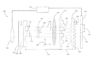
- FIG. 2 is an exemplary schematic diagram of a three-grating PCI system that invokes a phase stepping technique for extraction of phase shift information
- FIG. 3 is an exemplary intensity curve formed by stepping the absorption grating of FIG. 2 in the x direction;
- FIG. 4 is a view of the XZ cross section of a digitally modeled compressed breast
- FIGS. 5A-C are reconstructed images of linear attenuation ⁇ t, differential phase shift ⁇ t, and integrated phase shift
- FIG. 6 is an integrated phase shift image obtained by regularized integration of
- FIGS. 7A-B are reconstructed images of thickness maps for adipose tissue and glandular tissue, respectively;
- FIGS. 8A-B are example profiles across the x direction for theoretical and calculated thickness values of adipose and glandular tissues.
- FIG. 9 illustrates breast density as a function of y profile.
- interferometric x-ray imaging devices which utilize the wave nature of x-ray radiation.
- imaging interferometers focus on measuring the refraction characteristics manifested in the process of x-rays passing through the object of study.
- these devices can provide differential phase contrast and dark-field images.
- Differential phase contrast images contain the information of x-ray phase shift properties through the object of study, i.e., similar to absorption imaging providing complementary knowledge of material properties.
- dark-field image provides the information about the local scattering of the object, which will not be discussed herein in detail.
- One example of an object that may benefit from embodiments of the scanning and analysis invention disclosed herein is breast examination.
- the human female breast is primarily composed of two types of tissue: glandular and adipose.
- image data in the form of a projection detector voxel may contain any combination of these tissues.
- the total attenuation of the x-ray energy represented in a voxel may be expressed as a sum of attenuations through glandular and adipose tissues.
- data representing phase shifts, which an x-ray beam experiences, of various magnitudes, when it is passing through an object For an x-ray, passed through an adipose tissue of thickness t a and glandular tissue of thickness t g , the total attenuation and phase shift may be written in the following way:
- ⁇ a and ⁇ g are the linear attenuations per unit of length
- ⁇ a and ⁇ g are the phase shifts per unit of length, for the adipose and glandular tissues, respectively.
- FIGS. 1A-B illustrates in the curves shown in FIGS. 1A-B , wherein FIG. 1A illustrates a calibration curve for linear attenuation per unit length (1/cm) of adipose tissue 102 and of glandular tissue 104 ; FIG. 1B illustrates a calibration curve for phase shift per unit length (rad/cm) of adipose tissue 106 and of glandular tissue 108 .
- FIGS. 1A-B illustrates a calibration curve for linear attenuation per unit length (1/cm) of adipose tissue 102 and of glandular tissue 104 ;
- FIG. 1B illustrates a calibration curve for phase shift per unit length (rad/cm) of adipose tissue 106 and of glandular tissue 108 .
- rad/cm phase shift per unit length
- phase contrast acquisition technique e.g., system or method
- any phase change acquisition technique e.g., system or method
- differential phase contrast imaging technique where absorption and differential phase images are retrieved, it is convenient to write a solution of equation (1) in the following form:
- t a and t g represent the thickness maps of adipose and glandular tissues, respectively.
- Total transmission ⁇ t (also attenuation or absorption) and total differential phase shift ⁇ ( ⁇ t)/ ⁇ x along a linear trajectory t may be measured during the scan, while ⁇ and ⁇ parameters for adipose and glandular tissues may be found from calibration as shown, for example, in FIGS. 1A-B .
- ⁇ and ⁇ parameters for adipose and glandular tissues may be found from calibration as shown, for example, in FIGS. 1A-B .
- one form of the breast density BD may be calculated as:
- the attenuation and phase shift may be calculated as:
- the refractive index may be expressed in terms of the atomic scattering factors f 1 and f 2 :
- any phase contrast imaging technique which provides absorption and phase shift information, may be used in the exemplary system and method embodiments in this application.
- the example of the three-grating differential phase contrast imaging apparatus 200 which may be used, is shown in FIG. 2 .
- the phase stepping acquisition technique is illustrated as an example, although any other acquisition technique may be used instead.
- an analyzer grating 226 of the three gratings, 206 , 216 , 226 may be periodically stepped in one direction (up or down, in the perspective of FIG. 2 ) as indicated by arrow 246 which is referenced herein as the x direction using the coordinate system 220 .
- the grating 226 may be stepped over a total distance 238 with respect to the remainder of the gratings 206 , 216 , which may be kept stationary.
- the analyzer grating 226 may be stepped along the x axis over a distance 238 equal to a pitch of the grating 226 .
- the x-ray source 202 may be fired to expose the object 224 via filter 204 , collimator 208 , and initial source grating 206 , comprising a slit size 210 and pitch 212 , which generates a more coherent x-ray beam 214 comprising a plurality of x-rays 218 propagating in the direction 236 .
- the x-ray intensity may be detected and measured by the detector 240 comprising pixels 244 each having a size dimension 242 .
- the measured intensity signal at each pixel across the plurality of captured images comprises a sinusoidal shape, as shown in FIG. 3 .
- This is due to the diffractive effect on the x-rays 218 caused by phase grating 216 , whereby the x-rays 218 of the x-ray beam 214 are diffracted along paths 230 causing a sinusoidal variation in intensity 232 near the grating 226 .
- variable (sinusoidal) intensity of the x-rays are detected at corresponding pixels 244 of the digital x-ray detector 240 .
- the distance 222 between the grating 206 and the grating 216 as well as the distance 234 between the grating 216 and 226 may be adjusted for optimal image differentiation.
- the x-ray source 202 and the digital detector 240 may communicate with a control and image processing unit 201 over a connected cable or with a wireless transmitter to transmit radiographic image data wirelessly to the control and image processing unit 201 .
- the control and image processing unit 201 may include a processor and electronic memory (not shown) to control operations of the imaging apparatus 200 as described herein by use of programmed instructions.
- the control and image processing unit 201 may also be used to control activation of the x-ray source 202 during a radiographic exposure, controlling an x-ray tube electric current magnitude, and thus the fluence of x-rays 218 in x-ray beam 214 , and the x-ray source voltage, and thus the energy level of the x-rays 218 in x-ray beam 214 .
- the control and image processing unit 201 may transmit image (pixel) data to a monitor based on the radiographic exposure data received from the array photosensitive pixel cells in the detector 240 . Taking into account that FIG.
- the grating pitch 212 of the source grating 206 may be selected at about 50-100 ⁇ m; the grating pitch 228 of the phase grating 216 may be selected at about 4 ⁇ m; and the grating pitch 238 of the analyzer grating 226 selected at about half that, i.e. about 2 ⁇ m, of the phase grating 216 .
- the signal oscillation curve (or intensity curve) for each of the detector's pixels 244 (i,j), where i and j designate rows and columns of the detector 140 photosensitive elements, may be expressed as
- I b ⁇ ( i , j , x g ) a b ⁇ ( i , j ) + b b ⁇ ( i , j ) ⁇ cos ⁇ ( 2 ⁇ ⁇ p 2 ⁇ x g + ⁇ b ⁇ ( i , j ) + 2 ⁇ ⁇ p 2 ⁇ n ⁇ ⁇ ⁇ ⁇ ⁇ x g ) , ( 7 )
- a is the average intensity
- h is the signal amplitude
- x g is the lateral position of the grating at the n th step of phase stepping ( ⁇ x g ) 308 (see FIG. 3 ).
- the minimal number of steps required for successful image reconstruction is preferably three (3).
- I s ⁇ ( i , j , x g ) T s ⁇ ( i , j ) ⁇ [ a b ⁇ ( i , j ) + b b ⁇ ( i , j ) ⁇ cos ⁇ ( 2 ⁇ ⁇ p 2 ⁇ x g + ⁇ b ⁇ ( i , j ) + ⁇ s ⁇ ( i , j ) + 2 ⁇ ⁇ p 2 ⁇ n ⁇ ⁇ ⁇ ⁇ x g ) ] ( 8 )
- T s is the intensity of
- ⁇ s is the change of the phase of, the x-ray beam when it passes through the object. 4.
- a 3D digital phantom of the object was modeled by using 2D digital images 400 of a breast cross section in the XZ plane (in reference to coordinate system 220 shown in FIG. 2 ).
- Three different code values were assigned to the areas that represented air 402 , glandular 404 , and, adipose 406 tissues, as shown in FIG. 4 .
- the XZ cross sectional images of ⁇ and ⁇ (“map” images) of the breast may be generated.
- the map images may used in equation (5) to get the line integrals along the direction of the x-ray beam (i.e., the z axis), which may result in line profiles along the x axis for attenuation and phase shift through the phantom.
- the third y axis dimension it was assumed that the object had exactly the same XZ cross sectional area at any y coordinate. In other words, the x line profiles were stretched along the y axis.
- the model of x-ray spectrum propagation through each of the gratings was developed with the help of experimentally measured half-value layers.
- a cascaded system analysis (“CSA”) was performed to model a flat panel charge integrating detector ( 240 ) having a 100 ⁇ m thick GdO 2 S scintillator.
- the x-ray spectral propagation analysis together with CSA and additional dose measurements allowed modeling realistic noise, which was added to the model images via equations (7) and (8).
- the data reconstruction was done by employing Fourier analysis technique.
- the phase stepping acquisition technique requires multiple x-ray exposures each at a different lateral position x g (i.e., in x-axis) of the analyzer grating 226 (or relative displacement of any of the three gratings with respect to each other), which allows the generation of an intensity plot 300 , for example, a cosine (or sine) shaped intensity curve 306 shown in FIG. 3 having a wavelength 304 which represents the output of one pixel (i,j) wherein i, j, represent a column and row index identifying a particular pixel.
- the six data points 302 on the example plot 300 represent each of six captured radiographic images at each translated step of the analyzer grating 226 .
- the signal oscillation detected by each pixel of the detector 240 comprises information with respect to an intensity level (absorption) of the captured x-ray (I(i, j, x) vertical axis) and a phase angle ( ⁇ (i,j) horizontal axis).
- Equation (9) represents the intensity measurement with object present
- Equation (10) refers to measurement without an object, i.e. a reference scan or open field measurement.
- T ⁇ ( i , j ) a s ⁇ ( i , j ) a b ⁇ ( i , j ) , ( 11 )
- V ⁇ ( i , j ) b s ⁇ ( i , j ) / a s ⁇ ( i , j ) b b ⁇ ( i , j ) / a b ⁇ ( i , j ) , ( 12 )
- ⁇ i , j p 2 ⁇ ⁇ ⁇ d n ⁇ ⁇ ( ⁇ s ⁇ ( i , j ) - ⁇ b ⁇ ( i , j ) ) ⁇ dx . ( 14 )
- These four images of the object may be derived from the same data set and may be complementary to each other to provide multiple information of the scanned object enabling the visualization of subtle details in the object.
- FIGS. 5A-C show examples of reconstructed images of linear attenuation ( ⁇ t) in FIG. 5A , differential phase shift ( ⁇ ( ⁇ t)/ ⁇ x) in FIG. 5B , and integrated phase shift ( ⁇ t) in FIG. 5C .
- the integrated phase image is a result of integration of ⁇ ( ⁇ t)/ ⁇ x in the x direction, i.e.
- FIGS. 5A and 5C may be needed for calculating adipose and glandular thickness maps.
- the integrated phase shift image contains multiple streak artifacts in the direction of integration (e.g., x-direction).
- the precision of breast density measurement may be compromised. Therefore, to get accurate measurements it may be highly important to remove streak artifacts from the integrated phase shift image prior to breast density assessment.
- the artifact cleaning may involve any type of image denoising algorithms, applied to integrated phase shift image.
- the phase integration may be performed with a regularization term, which would provide smoothing in the y-axis (or in both x and y axes).
- denoising algorithms may be applied to any of the three images, for example the linear attenuation ( FIG. 5A ) and differential phase ( FIG. 5B ) images prior to integration or regularized integration.
- FIG. 6 An example of regularized integration of the differential phase contrast image is shown in FIG. 6 , whereby the streak artifacts are significantly reduced.
- FIGS. 7A and 7B show reconstructed images of thickness maps for adipose and glandular tissues, respectively, calculated by using equation (2).
- the calculated curves repeat the trend of the theoretical curve, although offset in some parts. Smoothing (or regularized integration) may provide better results, where the match between theoretical and calculated adipose and glandular curves may be improved.
- FIG. 9 shows breast density individually estimated for each y profile. Since the projection of the digital phantom was stretched in y direction to simulate the 2D projection of the breast, the breast density values theoretically should be the same for any y profile. This would be true if result images would be noise-free. However, due to noise in the images, the values of the breast density fluctuate around some mean value, which is close to the theoretical prediction. The spread of such fluctuations may be decreased by lowering the noise in the images, which may be done by using a detector with lower noise characteristics, for example CsI detector or Cd—Zn—Te detector.
- Breast density calculated by exemplary system and method embodiments according to this application, may provide rough estimates of breast density, as complementary information to routine breast screening with phase contrast imaging.
- the scatter may significantly alter the results of breast density calculations, especially for dense breasts. Therefore, a scatter correction may be necessary prior to applying the exemplary system and method embodiments.
- the present application contemplates methods and program products on any computer readable media for accomplishing its operations. Exemplary embodiments according to the present application may be implemented using an existing computer processor, or by a special purpose computer processor incorporated for this or another purpose or by a hardwired system.
- Also known in the art may be digital radiographic imaging panels that utilize an array of pixels comprising an x-ray absorbing photoconductor, such as amorphous Selenium (a-Se), and a readout circuit. Since the x-rays may be absorbed in the photoconductor, no separate scintillating screen is required.
- an x-ray absorbing photoconductor such as amorphous Selenium (a-Se)
- a-Se amorphous Selenium
- NDT non-destructive testing
- the present invention may be embodied as a system, method, or computer program product. Accordingly, embodiments of the present invention may be in the form of an entirely hardware embodiment, an entirely software embodiment (including firmware, resident software, stored model data, micro-code, and other suitable encodings) or an embodiment combining software and hardware aspects that may all generally be referred to herein as a “circuit” or “system.” Furthermore, the present invention may take the form of a computer program product embodied in a computer-readable storage medium, with instructions executed by one or more computers or host processors.
- This medium may comprise, for example: magnetic storage media such as a magnetic disk (such as a hard drive or a floppy disk) or magnetic tape; optical storage media such as an optical disc, optical tape, or machine readable bar code; solid state electronic storage devices such as solid state hard drives, random access memory (RAM), or read only memory (ROM); or any other physical device or medium employed to store a computer program.
- the computer program for performing the method of the present invention may also be stored on computer readable storage medium that may be connected to a host processor by way of the internet or other communication medium.
- the computer-usable or computer-readable medium could even be paper or another suitable medium upon which executable instructions may be printed, as the instructions may be electronically captured, via, for instance, optical scanning of the paper or other medium, then compiled, interpreted, or otherwise processed in a suitable manner, if necessary, and then stored in a computer memory.
- a computer-usable or computer-readable medium may be any medium that may contain, store, communicate, propagate, or transport computer instructions for use by, or in connection with, an instruction execution system, apparatus, or device.
- Exemplary embodiments described herein relate to methods and systems of operating a digital x-ray detector for the purpose of non-invasive or automatic x-ray beam detection. Exemplary embodiments described herein relate to methods and systems of operating a digital x-ray detector using continuously read out of the imaging panel, and the image data monitored to determine when the exposure occurred. Image data may be summed for all captured frames and may be corrected using dark image captures conducted before and after exposed frame acquisition. Exemplary embodiments described herein relate to methods and systems of operating a digital x-ray detector using multi-sample (e.g., two) continuously read out of the imaging panel (e.g., row by row).
- multi-sample e.g., two
- Exemplary embodiments described herein relate to methods and systems of operating a digital x-ray detector using multi-sample (e.g., two) continuously read out of the imaging panel (e.g., row by row) where the second read out of each row may be used for image correction of at least part of an x-ray exposure image.
- Exemplary embodiments described herein relate to methods and systems of operating a digital x-ray detector using multi-sample (e.g., two) continuously read out of the imaging panel that have been demonstrated to deliver robust beam sensing and acceptable imaging performance.
Abstract
Description
respectively;
where t=ta+tg is the distance that the x-ray traveled in the object, where μa and μg are the linear attenuations per unit of length, and φa and φg are the phase shifts per unit of length, for the adipose and glandular tissues, respectively. These values are not only dependent on the tissue type, but also on the level of x-ray energy used. Both may be found by doing calibration runs with x-ray exposures at different mean energies and tabulating the measurements, and are generally known for particular medical images based on numerous accumulated data. Examples of such calibration runs are illustrates in the curves shown in
Simulation
1. Modeling of Absorption and Phase Shift in the Materials
n=1−δ+iβ, (4)
where the imaginary part β contributes to the attenuation of the amplitude (absorption) and the real part δ (refraction index decrement) is responsible for the phase shift. When the x-ray is passing through the material, or object, the attenuation and phase shift may be calculated as:
where re, Na, λ, and ρ are the electron radius, Avogadro number, photon wavelength, and effective density of the material, respectively. The summation may be taken over the relative concentrations xk of each of the chemical elements of atomic mass Ak comprising the material. The calibration curves presented in
2. Exemplary Differential Phase Contrast Imaging System
where a is the average intensity, h is the signal amplitude, xg is the lateral position of the grating at the nth step of phase stepping (Δxg) 308 (see
where Ts is the intensity of, and φs is the change of the phase of, the x-ray beam when it passes through the object.
4. Modeling of Digital Phantom
-
- 1) transmission image:
-
- 2) dark-field image:
-
- 3) differential phase contrast image:
-
- 4) integrated phase contrast image:
As seen from equations (2), the first and third images,
Claims (23)
Priority Applications (1)
| Application Number | Priority Date | Filing Date | Title |
|---|---|---|---|
| US15/294,807 US9795350B2 (en) | 2012-12-21 | 2016-10-17 | Material differentiation with phase contrast imaging |
Applications Claiming Priority (10)
| Application Number | Priority Date | Filing Date | Title |
|---|---|---|---|
| US13/724,096 US20140177789A1 (en) | 2012-12-21 | 2012-12-21 | Grating-based differential phase contrast imaging system with adjustable capture technique for medical radiographic imaging |
| US13/729,443 US9001967B2 (en) | 2012-12-28 | 2012-12-28 | Spectral grating-based differential phase contrast system for medical radiographic imaging |
| US13/732,767 US8855395B2 (en) | 2013-01-02 | 2013-01-02 | Conditional likelihood material decomposition and methods of using the same |
| US201361884159P | 2013-09-30 | 2013-09-30 | |
| US201361892490P | 2013-10-18 | 2013-10-18 | |
| US14/143,183 US10096098B2 (en) | 2013-12-30 | 2013-12-30 | Phase retrieval from differential phase contrast imaging |
| US14/143,254 US9357975B2 (en) | 2013-12-30 | 2013-12-30 | Large FOV phase contrast imaging based on detuned configuration including acquisition and reconstruction techniques |
| US201461939925P | 2014-02-14 | 2014-02-14 | |
| US14/499,762 US9494534B2 (en) | 2012-12-21 | 2014-09-29 | Material differentiation with phase contrast imaging |
| US15/294,807 US9795350B2 (en) | 2012-12-21 | 2016-10-17 | Material differentiation with phase contrast imaging |
Related Parent Applications (2)
| Application Number | Title | Priority Date | Filing Date |
|---|---|---|---|
| US14/449,762 Continuation US9678492B2 (en) | 2012-02-01 | 2014-08-01 | Dynamic configuration of an industrial control system |
| US14/499,762 Continuation US9494534B2 (en) | 2012-12-21 | 2014-09-29 | Material differentiation with phase contrast imaging |
Publications (2)
| Publication Number | Publication Date |
|---|---|
| US20170035378A1 US20170035378A1 (en) | 2017-02-09 |
| US9795350B2 true US9795350B2 (en) | 2017-10-24 |
Family
ID=52740199
Family Applications (2)
| Application Number | Title | Priority Date | Filing Date |
|---|---|---|---|
| US14/499,762 Active 2035-03-14 US9494534B2 (en) | 2012-12-21 | 2014-09-29 | Material differentiation with phase contrast imaging |
| US15/294,807 Expired - Fee Related US9795350B2 (en) | 2012-12-21 | 2016-10-17 | Material differentiation with phase contrast imaging |
Family Applications Before (1)
| Application Number | Title | Priority Date | Filing Date |
|---|---|---|---|
| US14/499,762 Active 2035-03-14 US9494534B2 (en) | 2012-12-21 | 2014-09-29 | Material differentiation with phase contrast imaging |
Country Status (1)
| Country | Link |
|---|---|
| US (2) | US9494534B2 (en) |
Cited By (2)
| Publication number | Priority date | Publication date | Assignee | Title |
|---|---|---|---|---|
| US10578563B2 (en) | 2012-12-21 | 2020-03-03 | Carestream Health, Inc. | Phase contrast imaging computed tomography scanner |
| WO2020199194A1 (en) * | 2019-04-04 | 2020-10-08 | 中国科学技术大学 | X-ray phase-contrast imaging method |
Families Citing this family (34)
| Publication number | Priority date | Publication date | Assignee | Title |
|---|---|---|---|---|
| US20150117599A1 (en) | 2013-10-31 | 2015-04-30 | Sigray, Inc. | X-ray interferometric imaging system |
| US9724063B2 (en) | 2012-12-21 | 2017-08-08 | Carestream Health, Inc. | Surrogate phantom for differential phase contrast imaging |
| US9907524B2 (en) | 2012-12-21 | 2018-03-06 | Carestream Health, Inc. | Material decomposition technique using x-ray phase contrast imaging system |
| US9494534B2 (en) | 2012-12-21 | 2016-11-15 | Carestream Health, Inc. | Material differentiation with phase contrast imaging |
| US9700267B2 (en) | 2012-12-21 | 2017-07-11 | Carestream Health, Inc. | Method and apparatus for fabrication and tuning of grating-based differential phase contrast imaging system |
| US9357975B2 (en) | 2013-12-30 | 2016-06-07 | Carestream Health, Inc. | Large FOV phase contrast imaging based on detuned configuration including acquisition and reconstruction techniques |
| US10096098B2 (en) | 2013-12-30 | 2018-10-09 | Carestream Health, Inc. | Phase retrieval from differential phase contrast imaging |
| US10295485B2 (en) | 2013-12-05 | 2019-05-21 | Sigray, Inc. | X-ray transmission spectrometer system |
| US10416099B2 (en) | 2013-09-19 | 2019-09-17 | Sigray, Inc. | Method of performing X-ray spectroscopy and X-ray absorption spectrometer system |
| USRE48612E1 (en) | 2013-10-31 | 2021-06-29 | Sigray, Inc. | X-ray interferometric imaging system |
| US10401309B2 (en) | 2014-05-15 | 2019-09-03 | Sigray, Inc. | X-ray techniques using structured illumination |
| JP2016106721A (en) * | 2014-12-03 | 2016-06-20 | キヤノン株式会社 | Image processing device and image processing method |
| CN106793986A (en) * | 2015-05-06 | 2017-05-31 | 皇家飞利浦有限公司 | The optimization energy weighting of dark field signal in differential phase contrast x-ray imaging |
| JP6805173B2 (en) * | 2015-05-07 | 2020-12-23 | コーニンクレッカ フィリップス エヌ ヴェKoninklijke Philips N.V. | Beam hardening correction for scanning darkfield / phase contrast imaging |
| CN105388170B (en) * | 2015-12-17 | 2018-07-03 | 中国科学技术大学 | The measuring method and device of a kind of bone density |
| CN107807139B (en) * | 2016-09-05 | 2020-04-24 | 天津工业大学 | Dual-energy X-ray phase contrast imaging system without stepping device and implementation method thereof |
| US10247683B2 (en) | 2016-12-03 | 2019-04-02 | Sigray, Inc. | Material measurement techniques using multiple X-ray micro-beams |
| US10679384B2 (en) | 2017-09-29 | 2020-06-09 | General Electric Company | Systems and methods for deep learning-based image reconstruction |
| JP7069670B2 (en) * | 2017-12-04 | 2022-05-18 | コニカミノルタ株式会社 | X-ray system |
| WO2019130728A1 (en) * | 2017-12-25 | 2019-07-04 | 株式会社島津製作所 | Radiation phase contrast imaging device |
| US10578566B2 (en) | 2018-04-03 | 2020-03-03 | Sigray, Inc. | X-ray emission spectrometer system |
| WO2019236384A1 (en) | 2018-06-04 | 2019-12-12 | Sigray, Inc. | Wavelength dispersive x-ray spectrometer |
| US10658145B2 (en) | 2018-07-26 | 2020-05-19 | Sigray, Inc. | High brightness x-ray reflection source |
| US10656105B2 (en) | 2018-08-06 | 2020-05-19 | Sigray, Inc. | Talbot-lau x-ray source and interferometric system |
| DE112019004433T5 (en) | 2018-09-04 | 2021-05-20 | Sigray, Inc. | SYSTEM AND PROCEDURE FOR X-RAY FLUORESCENCE WITH FILTERING |
| CN112823280A (en) | 2018-09-07 | 2021-05-18 | 斯格瑞公司 | System and method for depth-selectable X-ray analysis |
| US11227418B2 (en) | 2018-12-28 | 2022-01-18 | General Electric Company | Systems and methods for deep learning-based image reconstruction |
| CN110133010B (en) * | 2019-04-04 | 2020-10-27 | 中国科学技术大学 | X-ray phase contrast imaging method |
| JP7182749B2 (en) | 2019-09-03 | 2022-12-02 | シグレイ、インコーポレイテッド | System and method for computed tomography fluorescence X-ray imaging |
| US11175243B1 (en) | 2020-02-06 | 2021-11-16 | Sigray, Inc. | X-ray dark-field in-line inspection for semiconductor samples |
| CN115667896A (en) | 2020-05-18 | 2023-01-31 | 斯格瑞公司 | System and method for X-ray absorption spectroscopy using a crystal analyzer and a plurality of detector elements |
| US11549895B2 (en) | 2020-09-17 | 2023-01-10 | Sigray, Inc. | System and method using x-rays for depth-resolving metrology and analysis |
| KR20230109735A (en) | 2020-12-07 | 2023-07-20 | 시그레이, 아이엔씨. | High-throughput 3D x-ray imaging system using transmitted x-ray source |
| US11885755B2 (en) | 2022-05-02 | 2024-01-30 | Sigray, Inc. | X-ray sequential array wavelength dispersive spectrometer |
Citations (64)
| Publication number | Priority date | Publication date | Assignee | Title |
|---|---|---|---|---|
| US5812629A (en) | 1997-04-30 | 1998-09-22 | Clauser; John F. | Ultrahigh resolution interferometric x-ray imaging |
| US6560309B1 (en) | 1999-11-28 | 2003-05-06 | Siemens Aktiengesellschaft | Method for examining a body region executing a periodic motion |
| US20050249328A1 (en) | 2004-05-04 | 2005-11-10 | Herbert Bruder | Method for taking tomograms of a beating heart |
| EP1731099A1 (en) | 2005-06-06 | 2006-12-13 | Paul Scherrer Institut | Interferometer for quantitative phase contrast imaging and tomography with an incoherent polychromatic x-ray source |
| US20070183582A1 (en) | 2006-02-01 | 2007-08-09 | Joachim Baumann | Focus-detector arrangement for generating projective or tomographic phase contrast recordings with X-ray optical gratings |
| US20070183560A1 (en) | 2006-02-01 | 2007-08-09 | Stefan Popescu | Method for producing projective and tomographic phase contrast images with the aid of an x-ray system |
| US20070183583A1 (en) | 2006-02-01 | 2007-08-09 | Joachim Baumann | Focus-detector arrangement of an X-ray apparatus for generating projective or tomographic phase contrast recordings |
| US20080009717A1 (en) | 2006-05-05 | 2008-01-10 | Klaus Herrmann | Method for generating a medical image and a medical imaging system |
| US20080014643A1 (en) | 2006-07-12 | 2008-01-17 | Paul Bjorkholm | Dual angle radiation scanning of objects |
| US7346204B2 (en) | 2001-05-16 | 2008-03-18 | Fujifilm Corporation | Method of and apparatus for generating phase contrast image |
| US20080075228A1 (en) | 2006-09-26 | 2008-03-27 | Tasaki Misae | Image radiographing system |
| US20080123805A1 (en) | 2006-09-29 | 2008-05-29 | Siemens Aktiengesellschaft | Method for x-ray image recording of a non-centric imaging area using an x-ray imaging system, and x-ray imaging system |
| US20080273653A1 (en) | 2006-12-27 | 2008-11-06 | Katsumi Niwa | Method of constructing multi-tomographic image and digital 3 D X-ray photographing apparatus |
| US7453981B2 (en) | 2006-02-01 | 2008-11-18 | Siemens Aktiengesellschaft | Focus-detector arrangement with X-ray optical grating for phase contrast measurement |
| US20090097730A1 (en) | 2005-05-23 | 2009-04-16 | Konica Minolta Medical & Graphic, Inc. | Abnormal shadow candidate display method and medical image processing system |
| US20090116720A1 (en) | 2005-07-01 | 2009-05-07 | Erik Leo Ritman | System and method for time-of-flight imaging |
| US7639786B2 (en) | 2006-02-01 | 2009-12-29 | Siemens Aktiengesellschaft | X-ray optical transmission grating of a focus-detector arrangement of an X-ray apparatus for generating projective or tomographic phase contrast recordings of a subject |
| US7693256B2 (en) | 2008-03-19 | 2010-04-06 | C-Rad Innovation Ab | Phase-contrast X-ray imaging |
| US20100220832A1 (en) | 2009-03-02 | 2010-09-02 | University Of Rochester | Methods and apparatus for differential phase-contrast fan beam ct, cone-beam ct and hybrid cone-beam ct |
| US20100220834A1 (en) | 2006-02-01 | 2010-09-02 | Heismann Bjoern | Method for Producing Projective and Tomographic Images Using an X-Ray System |
| US20100246764A1 (en) | 2008-04-15 | 2010-09-30 | Canon Kabushiki Kaisha | Source grating for x-rays, imaging apparatus for x-ray phase contrast image and x-ray computed tomography system |
| US20100246765A1 (en) | 2009-03-31 | 2010-09-30 | Fujifilm Corporation | Radiation phase contrast imaging apparatus |
| US7817777B2 (en) | 2005-12-27 | 2010-10-19 | Siemens Aktiengesellschaft | Focus detector arrangement and method for generating contrast x-ray images |
| US20100272235A1 (en) | 2009-04-28 | 2010-10-28 | Fujifilm Corporation | Radiation phase contrast imaging apparatus |
| US20110085639A1 (en) | 2009-10-09 | 2011-04-14 | Canon Kabushiki Kaisha | Phase grating used to take x-ray phase contrast image, imaging system using the phase grating, and x-ray computer tomography system |
| US20110135057A1 (en) | 2008-06-18 | 2011-06-09 | Hamamatsu Photonics K.K. | Solid-state image pickup device |
| US20110206181A1 (en) | 2009-07-15 | 2011-08-25 | Adani | Digital mammography scanning system |
| US20110243305A1 (en) | 2010-03-30 | 2011-10-06 | Fujifilm Corporation | Radiographic system, radiographic method and computer readable medium |
| WO2011122715A1 (en) | 2010-03-30 | 2011-10-06 | Fujifilm Corporation | Radiation detection device, radiographic apparatus and radiographic system |
| US20120020461A1 (en) | 2009-03-27 | 2012-01-26 | Koninklijke Philips Electronics N.V. | Achromatic phase-contrast imaging |
| US20120045108A1 (en) | 2009-05-07 | 2012-02-23 | Koninklijke Philips Electronics N.V. | System and method for generating a tomographic reconstruction filter |
| WO2012029048A1 (en) | 2010-09-03 | 2012-03-08 | Koninklijke Philips Electronics N.V. | Regularized phase retrieval in differential phase-contrast imaging |
| US20120057677A1 (en) | 2009-06-16 | 2012-03-08 | Koninklijke Philips Electronics N.V. | Tilted gratings and method for production of tilted gratings |
| US20120093284A1 (en) | 2009-06-25 | 2012-04-19 | Terumi Takemoto | X-ray photographing device |
| US20120114098A1 (en) | 2010-10-27 | 2012-05-10 | Fujifilm Corporation | Radiographic apparatus and radiographic system |
| WO2012080125A1 (en) | 2010-12-13 | 2012-06-21 | Paul Scherrer Institut | A method and a system for image integration using constrained optimization for phase contrast imaging with an arrangement of gratings |
| US20120163554A1 (en) | 2010-12-22 | 2012-06-28 | Fujifilm Corporation | Radiological image detection apparatus, radiographic apparatus and radiographic system |
| US20120250972A1 (en) | 2011-03-28 | 2012-10-04 | Fujifilm Corporation | Radiographic system and radiographic method |
| US20130028378A1 (en) | 2011-07-29 | 2013-01-31 | The Johns Hopkins University | Differential phase contrast x-ray imaging system and components |
| US8515002B2 (en) | 2009-07-07 | 2013-08-20 | Tsinghua University | X-ray dark-field imaging system and method |
| WO2013126296A1 (en) | 2012-02-24 | 2013-08-29 | University Of Massachusetts Medical School | Apparatus and method for x-ray phase contrast imaging |
| US20130259194A1 (en) | 2012-03-30 | 2013-10-03 | Kwok L. Yip | Hybrid slot-scanning grating-based differential phase contrast imaging system for medical radiographic imaging |
| US20130308750A1 (en) | 2010-10-27 | 2013-11-21 | Fujifilm Corporation | Radiographic system and radiographic image generating method |
| US20140044234A1 (en) | 2011-04-20 | 2014-02-13 | Fujifilm Corporation | Radiation imaging apparatus and image processing method |
| US20140177789A1 (en) | 2012-12-21 | 2014-06-26 | Pavlo Baturin | Grating-based differential phase contrast imaging system with adjustable capture technique for medical radiographic imaging |
| US20140185896A1 (en) | 2013-01-02 | 2014-07-03 | Pavlo Baturin | Conditional likelihood material decomposition and methods of using the same |
| US20140185746A1 (en) | 2012-12-28 | 2014-07-03 | Pavlo Baturin | Spectral grating-based differential phase contrast system for medical radiographic imaging |
| US20140226785A1 (en) | 2013-02-12 | 2014-08-14 | The Johns Hopkins University | System and method for phase-contrast x-ray imaging |
| US20140226783A1 (en) | 2013-02-11 | 2014-08-14 | University Of Rochester | Method and apparatus of spectral differential phase-contrast cone-beam ct and hybrid cone-beam ct |
| WO2014137318A1 (en) | 2012-03-05 | 2014-09-12 | University Of Rochester | Methods and apparatus for differential phase-contrast cone-beam ct and hybrid cone-beam ct |
| US20140270060A1 (en) | 2013-03-13 | 2014-09-18 | Canon Kabushiki Kaisha | X-ray talbot interferometer and x-ray talbot imaging system |
| US20140270061A1 (en) | 2013-03-12 | 2014-09-18 | Canon Kabushiki Kaisha | X-ray talbot interferometer and x-ray imaging system including talbot interferometer |
| US20140341347A1 (en) | 2011-09-16 | 2014-11-20 | Siemens Aktiengesellschaft | X-ray detector of a grating-based phase contrast x-ray device and method for operating a grating-based phase contrast x-ray device |
| US20140355740A1 (en) | 2012-01-12 | 2014-12-04 | Koninklijke Philips N.V. | Generating attenuation image data and phase image data in an x-ray system |
| US20150092916A1 (en) | 2012-12-21 | 2015-04-02 | Carestream Health, Inc. | Material differentiation with phase contrast imaging |
| US20150110247A1 (en) | 2012-12-21 | 2015-04-23 | Carestream Health, Inc. | Surrogate phantom for differential phase contrast imaging |
| US20150117599A1 (en) | 2013-10-31 | 2015-04-30 | Sigray, Inc. | X-ray interferometric imaging system |
| US20150131777A1 (en) * | 2012-06-11 | 2015-05-14 | Konica Minolta, Inc. | Medical imaging system and medical image processing apparatus |
| US20150187096A1 (en) | 2013-12-30 | 2015-07-02 | Carestream Health, Inc. | Phase retrieval from differential phase contrast imaging |
| US20150216499A1 (en) | 2012-08-20 | 2015-08-06 | Koninklijke Philips N.V. | Aligning source-grating-to-phase-grating distance for multiple order phase tuning in differential phase contrast imaging |
| US20160038107A1 (en) | 2012-12-21 | 2016-02-11 | Carestream Health, Inc. | Method and apparatus for fabrication and tuning of grating-based differential phase contrast imaging system |
| US20160095562A1 (en) | 2012-12-21 | 2016-04-07 | Carestream Health, Inc. | Material decomposition technique using x-ray phase contrast imaging system |
| US20160125599A1 (en) | 2013-06-07 | 2016-05-05 | Paul Scherrer Institut | Image fusion scheme for differential phase contrast imaging |
| US9357975B2 (en) | 2013-12-30 | 2016-06-07 | Carestream Health, Inc. | Large FOV phase contrast imaging based on detuned configuration including acquisition and reconstruction techniques |
-
2014
- 2014-09-29 US US14/499,762 patent/US9494534B2/en active Active
-
2016
- 2016-10-17 US US15/294,807 patent/US9795350B2/en not_active Expired - Fee Related
Patent Citations (73)
| Publication number | Priority date | Publication date | Assignee | Title |
|---|---|---|---|---|
| US5812629A (en) | 1997-04-30 | 1998-09-22 | Clauser; John F. | Ultrahigh resolution interferometric x-ray imaging |
| US6560309B1 (en) | 1999-11-28 | 2003-05-06 | Siemens Aktiengesellschaft | Method for examining a body region executing a periodic motion |
| US7346204B2 (en) | 2001-05-16 | 2008-03-18 | Fujifilm Corporation | Method of and apparatus for generating phase contrast image |
| US20050249328A1 (en) | 2004-05-04 | 2005-11-10 | Herbert Bruder | Method for taking tomograms of a beating heart |
| US20090097730A1 (en) | 2005-05-23 | 2009-04-16 | Konica Minolta Medical & Graphic, Inc. | Abnormal shadow candidate display method and medical image processing system |
| EP1731099A1 (en) | 2005-06-06 | 2006-12-13 | Paul Scherrer Institut | Interferometer for quantitative phase contrast imaging and tomography with an incoherent polychromatic x-ray source |
| US20090092227A1 (en) | 2005-06-06 | 2009-04-09 | Paul Scherrer Institut | Interferometer for quantitative phase contrast imaging and tomography with an incoherent polychromatic x-ray source |
| US20090116720A1 (en) | 2005-07-01 | 2009-05-07 | Erik Leo Ritman | System and method for time-of-flight imaging |
| US7817777B2 (en) | 2005-12-27 | 2010-10-19 | Siemens Aktiengesellschaft | Focus detector arrangement and method for generating contrast x-ray images |
| US7453981B2 (en) | 2006-02-01 | 2008-11-18 | Siemens Aktiengesellschaft | Focus-detector arrangement with X-ray optical grating for phase contrast measurement |
| DE102006015356A1 (en) | 2006-02-01 | 2007-08-09 | Siemens Ag | Method for producing projective and tomographic phase-contrast images with an X-ray system |
| US20070183582A1 (en) | 2006-02-01 | 2007-08-09 | Joachim Baumann | Focus-detector arrangement for generating projective or tomographic phase contrast recordings with X-ray optical gratings |
| US20070183560A1 (en) | 2006-02-01 | 2007-08-09 | Stefan Popescu | Method for producing projective and tomographic phase contrast images with the aid of an x-ray system |
| US20100220834A1 (en) | 2006-02-01 | 2010-09-02 | Heismann Bjoern | Method for Producing Projective and Tomographic Images Using an X-Ray System |
| US7646843B2 (en) | 2006-02-01 | 2010-01-12 | Siemens Aktiengesellschaft | Method for producing projective and tomographic phase contrast images with the aid of an X-ray system |
| US7639786B2 (en) | 2006-02-01 | 2009-12-29 | Siemens Aktiengesellschaft | X-ray optical transmission grating of a focus-detector arrangement of an X-ray apparatus for generating projective or tomographic phase contrast recordings of a subject |
| US20070183583A1 (en) | 2006-02-01 | 2007-08-09 | Joachim Baumann | Focus-detector arrangement of an X-ray apparatus for generating projective or tomographic phase contrast recordings |
| US20080009717A1 (en) | 2006-05-05 | 2008-01-10 | Klaus Herrmann | Method for generating a medical image and a medical imaging system |
| US20080014643A1 (en) | 2006-07-12 | 2008-01-17 | Paul Bjorkholm | Dual angle radiation scanning of objects |
| US20080075228A1 (en) | 2006-09-26 | 2008-03-27 | Tasaki Misae | Image radiographing system |
| US20080123805A1 (en) | 2006-09-29 | 2008-05-29 | Siemens Aktiengesellschaft | Method for x-ray image recording of a non-centric imaging area using an x-ray imaging system, and x-ray imaging system |
| US20080273653A1 (en) | 2006-12-27 | 2008-11-06 | Katsumi Niwa | Method of constructing multi-tomographic image and digital 3 D X-ray photographing apparatus |
| US7693256B2 (en) | 2008-03-19 | 2010-04-06 | C-Rad Innovation Ab | Phase-contrast X-ray imaging |
| US20100246764A1 (en) | 2008-04-15 | 2010-09-30 | Canon Kabushiki Kaisha | Source grating for x-rays, imaging apparatus for x-ray phase contrast image and x-ray computed tomography system |
| US20110135057A1 (en) | 2008-06-18 | 2011-06-09 | Hamamatsu Photonics K.K. | Solid-state image pickup device |
| US20100220832A1 (en) | 2009-03-02 | 2010-09-02 | University Of Rochester | Methods and apparatus for differential phase-contrast fan beam ct, cone-beam ct and hybrid cone-beam ct |
| US20120020461A1 (en) | 2009-03-27 | 2012-01-26 | Koninklijke Philips Electronics N.V. | Achromatic phase-contrast imaging |
| US20100246765A1 (en) | 2009-03-31 | 2010-09-30 | Fujifilm Corporation | Radiation phase contrast imaging apparatus |
| US20100272235A1 (en) | 2009-04-28 | 2010-10-28 | Fujifilm Corporation | Radiation phase contrast imaging apparatus |
| US20120045108A1 (en) | 2009-05-07 | 2012-02-23 | Koninklijke Philips Electronics N.V. | System and method for generating a tomographic reconstruction filter |
| US20120057677A1 (en) | 2009-06-16 | 2012-03-08 | Koninklijke Philips Electronics N.V. | Tilted gratings and method for production of tilted gratings |
| US20120093284A1 (en) | 2009-06-25 | 2012-04-19 | Terumi Takemoto | X-ray photographing device |
| US8515002B2 (en) | 2009-07-07 | 2013-08-20 | Tsinghua University | X-ray dark-field imaging system and method |
| US20110206181A1 (en) | 2009-07-15 | 2011-08-25 | Adani | Digital mammography scanning system |
| US20110085639A1 (en) | 2009-10-09 | 2011-04-14 | Canon Kabushiki Kaisha | Phase grating used to take x-ray phase contrast image, imaging system using the phase grating, and x-ray computer tomography system |
| US20130010926A1 (en) | 2010-03-30 | 2013-01-10 | Takuji Tada | Radiation detection device, radiographic apparatus and radiographic system |
| WO2011122715A1 (en) | 2010-03-30 | 2011-10-06 | Fujifilm Corporation | Radiation detection device, radiographic apparatus and radiographic system |
| US20110243305A1 (en) | 2010-03-30 | 2011-10-06 | Fujifilm Corporation | Radiographic system, radiographic method and computer readable medium |
| WO2012029048A1 (en) | 2010-09-03 | 2012-03-08 | Koninklijke Philips Electronics N.V. | Regularized phase retrieval in differential phase-contrast imaging |
| US20130156284A1 (en) | 2010-09-03 | 2013-06-20 | Koninklijke Philips Electronics N.V. | Regularized phase retrieval in differential phase-contrast imaging |
| US20130308750A1 (en) | 2010-10-27 | 2013-11-21 | Fujifilm Corporation | Radiographic system and radiographic image generating method |
| US20120114098A1 (en) | 2010-10-27 | 2012-05-10 | Fujifilm Corporation | Radiographic apparatus and radiographic system |
| WO2012080125A1 (en) | 2010-12-13 | 2012-06-21 | Paul Scherrer Institut | A method and a system for image integration using constrained optimization for phase contrast imaging with an arrangement of gratings |
| US20120163554A1 (en) | 2010-12-22 | 2012-06-28 | Fujifilm Corporation | Radiological image detection apparatus, radiographic apparatus and radiographic system |
| US20120250972A1 (en) | 2011-03-28 | 2012-10-04 | Fujifilm Corporation | Radiographic system and radiographic method |
| US20140044234A1 (en) | 2011-04-20 | 2014-02-13 | Fujifilm Corporation | Radiation imaging apparatus and image processing method |
| US20130028378A1 (en) | 2011-07-29 | 2013-01-31 | The Johns Hopkins University | Differential phase contrast x-ray imaging system and components |
| US20140341347A1 (en) | 2011-09-16 | 2014-11-20 | Siemens Aktiengesellschaft | X-ray detector of a grating-based phase contrast x-ray device and method for operating a grating-based phase contrast x-ray device |
| US20140355740A1 (en) | 2012-01-12 | 2014-12-04 | Koninklijke Philips N.V. | Generating attenuation image data and phase image data in an x-ray system |
| WO2013126296A1 (en) | 2012-02-24 | 2013-08-29 | University Of Massachusetts Medical School | Apparatus and method for x-ray phase contrast imaging |
| WO2014137318A1 (en) | 2012-03-05 | 2014-09-12 | University Of Rochester | Methods and apparatus for differential phase-contrast cone-beam ct and hybrid cone-beam ct |
| US20130259194A1 (en) | 2012-03-30 | 2013-10-03 | Kwok L. Yip | Hybrid slot-scanning grating-based differential phase contrast imaging system for medical radiographic imaging |
| US20150131777A1 (en) * | 2012-06-11 | 2015-05-14 | Konica Minolta, Inc. | Medical imaging system and medical image processing apparatus |
| US20150216499A1 (en) | 2012-08-20 | 2015-08-06 | Koninklijke Philips N.V. | Aligning source-grating-to-phase-grating distance for multiple order phase tuning in differential phase contrast imaging |
| US20160038107A1 (en) | 2012-12-21 | 2016-02-11 | Carestream Health, Inc. | Method and apparatus for fabrication and tuning of grating-based differential phase contrast imaging system |
| US20160095562A1 (en) | 2012-12-21 | 2016-04-07 | Carestream Health, Inc. | Material decomposition technique using x-ray phase contrast imaging system |
| US20150110247A1 (en) | 2012-12-21 | 2015-04-23 | Carestream Health, Inc. | Surrogate phantom for differential phase contrast imaging |
| US9494534B2 (en) | 2012-12-21 | 2016-11-15 | Carestream Health, Inc. | Material differentiation with phase contrast imaging |
| US20150092916A1 (en) | 2012-12-21 | 2015-04-02 | Carestream Health, Inc. | Material differentiation with phase contrast imaging |
| US20140177789A1 (en) | 2012-12-21 | 2014-06-26 | Pavlo Baturin | Grating-based differential phase contrast imaging system with adjustable capture technique for medical radiographic imaging |
| US9001967B2 (en) | 2012-12-28 | 2015-04-07 | Carestream Health, Inc. | Spectral grating-based differential phase contrast system for medical radiographic imaging |
| US20140185746A1 (en) | 2012-12-28 | 2014-07-03 | Pavlo Baturin | Spectral grating-based differential phase contrast system for medical radiographic imaging |
| US8855395B2 (en) | 2013-01-02 | 2014-10-07 | Carestream Health, Inc. | Conditional likelihood material decomposition and methods of using the same |
| US20140185896A1 (en) | 2013-01-02 | 2014-07-03 | Pavlo Baturin | Conditional likelihood material decomposition and methods of using the same |
| US20140226783A1 (en) | 2013-02-11 | 2014-08-14 | University Of Rochester | Method and apparatus of spectral differential phase-contrast cone-beam ct and hybrid cone-beam ct |
| US20140226782A1 (en) | 2013-02-12 | 2014-08-14 | The Johns Hopkins University | Large field of view grating interferometers for x-ray phase contrast imaging and ct at high energy |
| US20140226785A1 (en) | 2013-02-12 | 2014-08-14 | The Johns Hopkins University | System and method for phase-contrast x-ray imaging |
| US20140270061A1 (en) | 2013-03-12 | 2014-09-18 | Canon Kabushiki Kaisha | X-ray talbot interferometer and x-ray imaging system including talbot interferometer |
| US20140270060A1 (en) | 2013-03-13 | 2014-09-18 | Canon Kabushiki Kaisha | X-ray talbot interferometer and x-ray talbot imaging system |
| US20160125599A1 (en) | 2013-06-07 | 2016-05-05 | Paul Scherrer Institut | Image fusion scheme for differential phase contrast imaging |
| US20150117599A1 (en) | 2013-10-31 | 2015-04-30 | Sigray, Inc. | X-ray interferometric imaging system |
| US20150187096A1 (en) | 2013-12-30 | 2015-07-02 | Carestream Health, Inc. | Phase retrieval from differential phase contrast imaging |
| US9357975B2 (en) | 2013-12-30 | 2016-06-07 | Carestream Health, Inc. | Large FOV phase contrast imaging based on detuned configuration including acquisition and reconstruction techniques |
Non-Patent Citations (22)
| Title |
|---|
| Bonse, et al., "An x-ray interferometer," Appl. Phys. Lett. 6(8), 155-156, (1965). |
| C. Kottler et al., Grating interferometer based scanning setup for hard x-ray phase contrast imaging, Review of Scientific Instruments, vol. 78, 034710, 2007, pp. 1-4. |
| Chapman, D., Thomlinson, et al., "Diffraction enhanced x-ray imaging," Phys. Med. Biol., 42, 2015, (1997). |
| Commonly assigned U.S. Appl. No. 14/143,183, entitled: Phase Retrieval From Differential Phase Contrast Imaging filed on Dec. 30, 2013, by Baturin et al. |
| Commonly assigned U.S. Appl. No. 14/143,254, entitled: Large FOV Phase Contrast Imaging Based on Detuned Configuration Including Acquisition and Reconstruction Techniques filed on Dec. 30, 2013, by Baturin et al. |
| Commonly assigned U.S. Appl. No. 61/892,490, entitled: Surrogate Phantom for Differential Phase Contrast Imaging filed on Oct. 18, 2013, by Baturin et al. |
| Commonly assigned U.S. Appl. No. 61/939,925, entitled: Method and Apparatus for Fabrication and Tuning of Grating-Based Differential Phase Contrast Imaging System filed on Feb. 14, 2014, by Baturin et al. |
| H.N. Cardinal and A. Fenster "An accurate method for direct dual-energy calibration and decomposition" Medical Physics, May-Jun. 1990; vol. 17, No. 3, pp. 327-341. |
| Ingal. V. N., et al., "X-ray plane-wave topography observation of the phase contrast from non-crystalline object," J. Phys. D 28(11), 2314-2317, (1995). |
| International Search Report, International application No. PCT/US2013/026301, dated Jun 3, 2013, 3 pages. |
| International Search Report, International application No. PCT/US2013/075898, dated Apr 22, 2014, 2 pages. |
| International Search Report, International application No. PCT/US2014/066027, dated May 2, 2015, 2 pages. |
| International Search Report, International application No. PCT/US2014/066033, dated Apr 28, 2015, 2 pages. |
| International Search Report, International application No. PCT/US2016/062389, dated Feb. 2, 2017, 2 pages. |
| Jian Fu et al., Helical differential X-Ray phase-contrast computed tomography, Physica Medica, vol. 30, pp. 374-379, 2014. |
| Momose, A., et al., "Demonstration of X-ray Talbot interferometry," Jpn. J. Appl. Phys. 42, L866-L868, (2003). |
| Pfeiffer, F., "Phase retrieval and differential phase-contrast imaging with low-brilliance X-ray sources", Nature Phys. 2, 258-261, (2006). |
| Supplementary European Search Report, dated Nov. 27, 2015, European Application No. 13769560.7, 2 pages. |
| Thomas Thuring, Compact X-ray grating interferometry for phase and dark-field computed tomography in the diagnostic energy range, Swiss Federal Institute of Technology Zurich, 2013, pp. 1-180. |
| Thomas Thuring, et al., Non-linear regularized phase retrieval for unidirectional X-ray differential phase contrast radiography, Optics Express, vol. 19, Issue 25, pp. 25545-25558, Optical Society of America 2011, issn: 10944087. |
| Wietkamp, T., et al., "X-ray phase imaging with a grating interferometer," Opt. Exp. 13(16), 6296-6304, (2006). |
| Wilkins, S. W., et al., "Phase-contrast imaging using polychromatic hard X-rays," Nature (London) 384(6607) 335-338, (1996). |
Cited By (2)
| Publication number | Priority date | Publication date | Assignee | Title |
|---|---|---|---|---|
| US10578563B2 (en) | 2012-12-21 | 2020-03-03 | Carestream Health, Inc. | Phase contrast imaging computed tomography scanner |
| WO2020199194A1 (en) * | 2019-04-04 | 2020-10-08 | 中国科学技术大学 | X-ray phase-contrast imaging method |
Also Published As
| Publication number | Publication date |
|---|---|
| US20170035378A1 (en) | 2017-02-09 |
| US9494534B2 (en) | 2016-11-15 |
| US20150092916A1 (en) | 2015-04-02 |
Similar Documents
| Publication | Publication Date | Title |
|---|---|---|
| US9795350B2 (en) | Material differentiation with phase contrast imaging | |
| US10481110B2 (en) | Radiographic image generating device | |
| US9907524B2 (en) | Material decomposition technique using x-ray phase contrast imaging system | |
| US8972191B2 (en) | Low dose single step grating based X-ray phase contrast imaging | |
| US9842414B2 (en) | Monochromatic attenuation contrast image generation by using phase contrast CT | |
| US8855395B2 (en) | Conditional likelihood material decomposition and methods of using the same | |
| US7545907B2 (en) | Methods and apparatus for obtaining low-dose imaging | |
| CN102802529B (en) | For the bearing calibration of differential contrast imaging | |
| US9724063B2 (en) | Surrogate phantom for differential phase contrast imaging | |
| CN104428659B (en) | Dark-field imaging | |
| US20130279659A1 (en) | Method and a system for image integration using constrained optimization for phase contrast imaging with an arragement of gratings | |
| JP7225432B2 (en) | In-line X-ray focusing optics used for manipulating X-rays in medical transmission radiography | |
| CN105628718A (en) | Multi-energy-spectrum X-ray grating imaging system and imaging method | |
| WO2007125833A1 (en) | X-ray image picking-up device and x-ray image picking-up method | |
| EP3383273B1 (en) | Apparatus for x-ray imaging an object | |
| US20140169522A1 (en) | Medical imaging system | |
| JP2012200567A (en) | Radiographic system and radiographic method | |
| JP2017027357A (en) | Image processing unit, imaging system and image processing method | |
| US20150117595A1 (en) | Method and x-ray system for generating a phase contrast image | |
| JP6148415B1 (en) | Computed tomography (CT) hybrid data collection | |
| US20150310609A1 (en) | Systems and methods for regularized fourier analysis in x-ray phase contrast imaging | |
| CN109561868B (en) | Phantom device for acquiring dark field images, dark field imaging system and method | |
| WO2012147749A1 (en) | Radiography system and radiography method | |
| JP2012228369A (en) | Radiographic system, and radiographic method | |
| Nelson | Complementarity of Multiple X-Ray Contrasts in Characterization of Pulmonary Fibrosis with Grating Interferometer Micro-CT |
Legal Events
| Date | Code | Title | Description |
|---|---|---|---|
| STCF | Information on status: patent grant |
Free format text: PATENTED CASE |
|
| AS | Assignment |
Owner name: CREDIT SUISSE AG, CAYMAN ISLANDS BRANCH, NEW YORK Free format text: SECURITY INTEREST;ASSIGNORS:CARESTREAM HEALTH, INC.;CARESTREAM HEALTH HOLDINGS, INC.;CARESTREAM HEALTH CANADA HOLDINGS, INC.;AND OTHERS;REEL/FRAME:048077/0587 Effective date: 20190114 Owner name: CREDIT SUISSE AG, CAYMAN ISLANDS BRANCH, NEW YORK Free format text: SECURITY INTEREST;ASSIGNORS:CARESTREAM HEALTH, INC.;CARESTREAM HEALTH HOLDINGS, INC.;CARESTREAM HEALTH CANADA HOLDINGS, INC.;AND OTHERS;REEL/FRAME:048077/0529 Effective date: 20190114 |
|
| FEPP | Fee payment procedure |
Free format text: MAINTENANCE FEE REMINDER MAILED (ORIGINAL EVENT CODE: REM.); ENTITY STATUS OF PATENT OWNER: LARGE ENTITY |
|
| LAPS | Lapse for failure to pay maintenance fees |
Free format text: PATENT EXPIRED FOR FAILURE TO PAY MAINTENANCE FEES (ORIGINAL EVENT CODE: EXP.); ENTITY STATUS OF PATENT OWNER: LARGE ENTITY |
|
| STCH | Information on status: patent discontinuation |
Free format text: PATENT EXPIRED DUE TO NONPAYMENT OF MAINTENANCE FEES UNDER 37 CFR 1.362 |
|
| FP | Lapsed due to failure to pay maintenance fee |
Effective date: 20211024 |
|
| AS | Assignment |
Owner name: JPMORGAN CHASE BANK, N.A., ILLINOIS Free format text: GRANT OF SECURITY INTEREST IN PATENT RIGHTS - TL;ASSIGNOR:CARESTREAM HEALTH, INC.;REEL/FRAME:061579/0341 Effective date: 20220930 Owner name: JPMORGAN CHASE BANK, N.A., ILLINOIS Free format text: GRANT OF SECURITY INTEREST IN PATENT RIGHTS - ABL;ASSIGNOR:CARESTREAM HEALTH, INC.;REEL/FRAME:061579/0301 Effective date: 20220930 |
|
| AS | Assignment |
Owner name: CARESTREAM HEALTH WORLD HOLDINGS LLC, NEW YORK Free format text: RELEASE OF SECURITY INTEREST IN INTELLECTUAL PROPERTY (FIRST LIEN);ASSIGNOR:CREDIT SUISSE AG, CAYMAN ISLANDS BRANCH;REEL/FRAME:061683/0529 Effective date: 20220930 Owner name: CARESTREAM HEALTH ACQUISITION, LLC, NEW YORK Free format text: RELEASE OF SECURITY INTEREST IN INTELLECTUAL PROPERTY (FIRST LIEN);ASSIGNOR:CREDIT SUISSE AG, CAYMAN ISLANDS BRANCH;REEL/FRAME:061683/0529 Effective date: 20220930 Owner name: CARESTREAM HEALTH CANADA HOLDINGS, INC., NEW YORK Free format text: RELEASE OF SECURITY INTEREST IN INTELLECTUAL PROPERTY (FIRST LIEN);ASSIGNOR:CREDIT SUISSE AG, CAYMAN ISLANDS BRANCH;REEL/FRAME:061683/0529 Effective date: 20220930 Owner name: CARESTREAM HEALTH HOLDINGS, INC., NEW YORK Free format text: RELEASE OF SECURITY INTEREST IN INTELLECTUAL PROPERTY (FIRST LIEN);ASSIGNOR:CREDIT SUISSE AG, CAYMAN ISLANDS BRANCH;REEL/FRAME:061683/0529 Effective date: 20220930 Owner name: CARESTREAM HEALTH, INC., NEW YORK Free format text: RELEASE OF SECURITY INTEREST IN INTELLECTUAL PROPERTY (FIRST LIEN);ASSIGNOR:CREDIT SUISSE AG, CAYMAN ISLANDS BRANCH;REEL/FRAME:061683/0529 Effective date: 20220930 Owner name: CARESTREAM HEALTH WORLD HOLDINGS LLC, NEW YORK Free format text: RELEASE OF SECURITY INTEREST IN INTELLECTUAL PROPERTY (SECOND LIEN);ASSIGNOR:CREDIT SUISSE AG, CAYMAN ISLANDS BRANCH;REEL/FRAME:061683/0681 Effective date: 20220930 Owner name: CARESTREAM HEALTH ACQUISITION, LLC, NEW YORK Free format text: RELEASE OF SECURITY INTEREST IN INTELLECTUAL PROPERTY (SECOND LIEN);ASSIGNOR:CREDIT SUISSE AG, CAYMAN ISLANDS BRANCH;REEL/FRAME:061683/0681 Effective date: 20220930 Owner name: CARESTREAM HEALTH CANADA HOLDINGS, INC., NEW YORK Free format text: RELEASE OF SECURITY INTEREST IN INTELLECTUAL PROPERTY (SECOND LIEN);ASSIGNOR:CREDIT SUISSE AG, CAYMAN ISLANDS BRANCH;REEL/FRAME:061683/0681 Effective date: 20220930 Owner name: CARESTREAM HEALTH HOLDINGS, INC., NEW YORK Free format text: RELEASE OF SECURITY INTEREST IN INTELLECTUAL PROPERTY (SECOND LIEN);ASSIGNOR:CREDIT SUISSE AG, CAYMAN ISLANDS BRANCH;REEL/FRAME:061683/0681 Effective date: 20220930 Owner name: CARESTREAM HEALTH, INC., NEW YORK Free format text: RELEASE OF SECURITY INTEREST IN INTELLECTUAL PROPERTY (SECOND LIEN);ASSIGNOR:CREDIT SUISSE AG, CAYMAN ISLANDS BRANCH;REEL/FRAME:061683/0681 Effective date: 20220930 |