WO2023149086A1 - 熱回収装置、熱回収方法及び鋼板の製造方法 - Google Patents
熱回収装置、熱回収方法及び鋼板の製造方法 Download PDFInfo
- Publication number
- WO2023149086A1 WO2023149086A1 PCT/JP2022/045662 JP2022045662W WO2023149086A1 WO 2023149086 A1 WO2023149086 A1 WO 2023149086A1 JP 2022045662 W JP2022045662 W JP 2022045662W WO 2023149086 A1 WO2023149086 A1 WO 2023149086A1
- Authority
- WO
- WIPO (PCT)
- Prior art keywords
- heat
- temperature
- flow path
- water
- make
- Prior art date
- Legal status (The legal status is an assumption and is not a legal conclusion. Google has not performed a legal analysis and makes no representation as to the accuracy of the status listed.)
- Ceased
Links
Images



Classifications
-
- F—MECHANICAL ENGINEERING; LIGHTING; HEATING; WEAPONS; BLASTING
- F24—HEATING; RANGES; VENTILATING
- F24H—FLUID HEATERS, e.g. WATER OR AIR HEATERS, HAVING HEAT-GENERATING MEANS, e.g. HEAT PUMPS, IN GENERAL
- F24H4/00—Fluid heaters characterised by the use of heat pumps
- F24H4/02—Water heaters
-
- C—CHEMISTRY; METALLURGY
- C02—TREATMENT OF WATER, WASTE WATER, SEWAGE, OR SLUDGE
- C02F—TREATMENT OF WATER, WASTE WATER, SEWAGE, OR SLUDGE
- C02F1/00—Treatment of water, waste water, or sewage
- C02F1/02—Treatment of water, waste water, or sewage by heating
-
- C—CHEMISTRY; METALLURGY
- C23—COATING METALLIC MATERIAL; COATING MATERIAL WITH METALLIC MATERIAL; CHEMICAL SURFACE TREATMENT; DIFFUSION TREATMENT OF METALLIC MATERIAL; COATING BY VACUUM EVAPORATION, BY SPUTTERING, BY ION IMPLANTATION OR BY CHEMICAL VAPOUR DEPOSITION, IN GENERAL; INHIBITING CORROSION OF METALLIC MATERIAL OR INCRUSTATION IN GENERAL
- C23G—CLEANING OR DE-GREASING OF METALLIC MATERIAL BY CHEMICAL METHODS OTHER THAN ELECTROLYSIS
- C23G1/00—Cleaning or pickling metallic material with solutions or molten salts
- C23G1/36—Regeneration of waste pickling liquors
-
- C—CHEMISTRY; METALLURGY
- C23—COATING METALLIC MATERIAL; COATING MATERIAL WITH METALLIC MATERIAL; CHEMICAL SURFACE TREATMENT; DIFFUSION TREATMENT OF METALLIC MATERIAL; COATING BY VACUUM EVAPORATION, BY SPUTTERING, BY ION IMPLANTATION OR BY CHEMICAL VAPOUR DEPOSITION, IN GENERAL; INHIBITING CORROSION OF METALLIC MATERIAL OR INCRUSTATION IN GENERAL
- C23G—CLEANING OR DE-GREASING OF METALLIC MATERIAL BY CHEMICAL METHODS OTHER THAN ELECTROLYSIS
- C23G3/00—Apparatus for cleaning or pickling metallic material
- C23G3/02—Apparatus for cleaning or pickling metallic material for cleaning wires, strips, filaments continuously
- C23G3/027—Associated apparatus, e.g. for pretreating or after-treating
-
- F—MECHANICAL ENGINEERING; LIGHTING; HEATING; WEAPONS; BLASTING
- F24—HEATING; RANGES; VENTILATING
- F24H—FLUID HEATERS, e.g. WATER OR AIR HEATERS, HAVING HEAT-GENERATING MEANS, e.g. HEAT PUMPS, IN GENERAL
- F24H1/00—Water heaters, e.g. boilers, continuous-flow heaters or water-storage heaters
-
- F—MECHANICAL ENGINEERING; LIGHTING; HEATING; WEAPONS; BLASTING
- F24—HEATING; RANGES; VENTILATING
- F24H—FLUID HEATERS, e.g. WATER OR AIR HEATERS, HAVING HEAT-GENERATING MEANS, e.g. HEAT PUMPS, IN GENERAL
- F24H1/00—Water heaters, e.g. boilers, continuous-flow heaters or water-storage heaters
- F24H1/10—Continuous-flow heaters, i.e. heaters in which heat is generated only while the water is flowing, e.g. with direct contact of the water with the heating medium
- F24H1/12—Continuous-flow heaters, i.e. heaters in which heat is generated only while the water is flowing, e.g. with direct contact of the water with the heating medium in which the water is kept separate from the heating medium
-
- C—CHEMISTRY; METALLURGY
- C23—COATING METALLIC MATERIAL; COATING MATERIAL WITH METALLIC MATERIAL; CHEMICAL SURFACE TREATMENT; DIFFUSION TREATMENT OF METALLIC MATERIAL; COATING BY VACUUM EVAPORATION, BY SPUTTERING, BY ION IMPLANTATION OR BY CHEMICAL VAPOUR DEPOSITION, IN GENERAL; INHIBITING CORROSION OF METALLIC MATERIAL OR INCRUSTATION IN GENERAL
- C23G—CLEANING OR DE-GREASING OF METALLIC MATERIAL BY CHEMICAL METHODS OTHER THAN ELECTROLYSIS
- C23G1/00—Cleaning or pickling metallic material with solutions or molten salts
- C23G1/02—Cleaning or pickling metallic material with solutions or molten salts with acid solutions
- C23G1/08—Iron or steel
-
- Y—GENERAL TAGGING OF NEW TECHNOLOGICAL DEVELOPMENTS; GENERAL TAGGING OF CROSS-SECTIONAL TECHNOLOGIES SPANNING OVER SEVERAL SECTIONS OF THE IPC; TECHNICAL SUBJECTS COVERED BY FORMER USPC CROSS-REFERENCE ART COLLECTIONS [XRACs] AND DIGESTS
- Y02—TECHNOLOGIES OR APPLICATIONS FOR MITIGATION OR ADAPTATION AGAINST CLIMATE CHANGE
- Y02B—CLIMATE CHANGE MITIGATION TECHNOLOGIES RELATED TO BUILDINGS, e.g. HOUSING, HOUSE APPLIANCES OR RELATED END-USER APPLICATIONS
- Y02B30/00—Energy efficient heating, ventilation or air conditioning [HVAC]
- Y02B30/52—Heat recovery pumps, i.e. heat pump based systems or units able to transfer the thermal energy from one area of the premises or part of the facilities to a different one, improving the overall efficiency
Definitions
- the present invention relates to a heat recovery device, a heat recovery method, and a method for manufacturing a steel plate using the heat recovery method in a steel plate cleaning process.
- Patent Literature 1 proposes a device that uses a heat pump to improve the heat utilization efficiency of a heat source.
- the present invention has been made in view of the above circumstances, and an object of the present invention is to propose a heat recovery device and a heat recovery method that maximize the energy saving effect in the cleaning treatment of steel plates. Another object of the present invention is to propose a steel manufacturing method using the heat recovery method.
- the inventors diligently conducted experiments and studies to solve the above problems. As a result, by combining heat pumps and heat exchangers, it is possible to maximize the energy saving effect by supplying heat at the appropriate temperature and flow rate to the heat pumps. It was found that the liquid to be introduced into the heat exchanger of the heat pump can be purified by this.
- a heat recovery device which advantageously solves the above problems, is configured as follows.
- [1] A first heat exchanger that exchanges heat between high-temperature waste water used in the steel plate cleaning process and make-up water for the cleaning process, and the waste water cooled through the first heat exchanger.
- a second heat exchanger that recovers heat by exchanging heat with the low temperature side heat source of the heat pump; and a heat pump that raises the temperature by electric power to the compressor and the evaporator and supplies it as high-temperature make-up water.
- the temperature of the make-up water raised by the heat pump is less than 100°C
- the temperature of the waste water sent to the heat pump for heat recovery is less than 90°C. It is a device.
- a flow path changing unit for changing a heat medium flow path in a heat medium flow path between the second heat exchanger and the heat pump, and the heat medium flow a measuring unit for measuring an inlet heat medium temperature T Ci entering the heat pump through a passage ; and a control unit that performs feedback control or feedforward control on the flow rate of the flow path changing unit so that ⁇ T C.
- the heat recovery device has a third heat exchanger that exchanges heat between the make-up water and the heat source on the high temperature side of the heat pump.
- a first flow path changing unit for changing a heat medium flow path in a first heat medium flow path between the second heat exchanger and the heat pump; a measuring unit for measuring an inlet heat medium temperature T Ci entering the heat pump through a medium flow path;
- a first control unit that performs feedback control or feedforward control of the flow rate of the first flow path changing unit so that T Ci ⁇ T C , and a second heat medium flow path between the third heat exchanger and the heat pump a second flow path changing section for changing the flow path of the heat medium in, a measuring section for measuring the outlet heat medium temperature T Ho entering the heat pump through the second heat medium flow path, and the outlet heat medium temperature
- a second control unit that performs feedback control or feedforward control of the flow rate of the second flow path changing unit so that T Ho ⁇ T H based on the heat medium temperature T Ho measured by the measurement unit, with the upper limit T H and a heat recovery device.
- heating means for heating the makeup water preheated by the heat pump to a temperature lower than the set temperature required for the cleaning process;
- the temperature flow rate of the make-up water to be preheated by the heat pump and the preheated make-up water are heated to the required supply temperature based on the temperature adjustment means for adjusting the temperature and the supply temperature and supply amount of the make-up water required for the cleaning process.
- a heat recovery device comprising: a controller for controlling the amount of energy of a heating means so as to reduce net energy consumption in consideration of energy loss from an energy source to a supply destination in a business establishment.
- a heat recovery method and a steel plate manufacturing method according to the present invention which advantageously solve the above problems, are configured as follows. [7] A first heat exchange step of exchanging heat between high-temperature waste water used in the steel plate washing process and make-up water for the washing process, and the waste water cooled through the first heat exchange process. a second heat exchange step of recovering heat by exchanging heat with a low temperature side heat source of a heat pump; and a wash water replenishment step of increasing the temperature of the compressor and the evaporator by electric power and supplying it as high-temperature replenishment water.
- the temperature of the make-up water heated by the heat pump is set to less than 100°C, and the temperature of the waste water sent to the heat pump and heat-recovered is set to less than 90°C.
- the method [9] In the above [7] or [8], a flow path changing unit for changing a heat medium flow path in a heat medium flow path between the heat pump in the second heat exchange step, Assuming that the inlet heat medium temperature entering the heat pump through the medium passage is T Ci , the upper limit of the inlet heat medium temperature is T C , and based on T Ci measured by the measurement unit, the temperature is adjusted so that T Ci ⁇ T C .
- This heat recovery method performs feedback control or feedforward control of the flow rate of the flow path changing portion.
- the inlet heat medium temperature is T Ci
- the upper limit of the inlet heat medium temperature is T C
- the flow rate of the first flow path changing section is adjusted so that T Ci ⁇ T C Feedback control or feedforward control is performed
- T Ho is the outlet heat medium temperature that exits the heat pump through the second heat medium flow path
- T is the upper limit of the outlet heat medium temperature
- T Ho is measured by the measurement unit. and feedback control or feedforward control of the flow rate of the second flow path changing portion so that T Ho ⁇ T H.
- This is a heat recovery method for controlling the energy amount of a heating means for heating so as to reduce the net energy consumption in consideration of the energy loss from the energy generation source to the supply destination of the business establishment.
- the present invention it is possible to provide a heat recovery device and method using a heat pump and a heat exchanger that can supply a heat medium efficiently and at low cost.
- a heat recovery method for heating replenishing water in the steel plate washing process an energy-saving and environmentally friendly steel plate can be manufactured.
- FIG. 5 is a system diagram showing an example of a configuration of a flow path changing unit in FIG. 4;
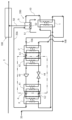
- FIG. 4 is a system diagram showing another embodiment having a flow path changing section of the present invention;
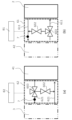
- (a) in FIG. 6 is a system diagram showing an example of the configuration of the second flow path changing section, and
- (b) is a system diagram showing an example of the configuration of the first flow path changing section.
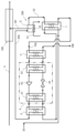
- FIG. 1 shows a heat recovery device used in a steel plate S cleaning process 100 .
- a first heat exchanger 1 performs heat exchange between high-temperature waste water 10 after washing used in the washing treatment of steel plate S and makeup water 20 for washing treatment. 20 is heated, and the high-temperature waste water 10 after washing is cooled.
- the second heat exchanger 2 which exchanges heat between the cooled waste water 10A after washing and the water of the heat pump 4, the cooled waste water 10A after washing is heat-exchanged with the low-temperature side heat source water of the heat pump 4 to recover heat.
- this second heat exchanger 2 it is possible to indirectly supply heat to the waste water 10A after washing, which has poor properties, without directly supplying it to the heat pump 4, which cannot be disassembled and washed. can be done.
- the make-up water 20 whose temperature has been raised by the first heat exchanger 1 is put into the high temperature side (condenser 41) of the heat pump 4, and the heat recovered on the low temperature side (evaporator 42) is sent to the compressor 43 and the evaporator 42.
- the temperature is raised by the supply of electric power, and is used in the cleaning liquid temperature adjustment process 200 as additional make-up water 20A.
- the heat pump 4 includes a general condenser (radiator) 41 , an evaporator (heat absorber) 42 , a compressor 43 and an expansion valve 44 .
- the temperature of the make-up water 20A heated by the heat pump 4 is preferably less than 100°C, and the post-washing waste water 10A sent to the heat pump 4 for heat recovery is preferably less than 90°C.
- the third heat exchanger 3 is disposed on the high temperature side of the heat pump (on the condenser 41 side).
- the make-up water 20 has better properties than the waste water 10 after washing, but by arranging the third heat exchanger 3 on the heat pump high temperature side (condenser 41 side), a liquid with even better properties can be used for the heat pump 4. This is because
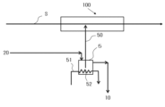
- Steam 51 and heaters 52 may be used in the cleaning liquid temperature adjustment process 200 to adjust the temperature of the cleaning liquid sent to the cleaning process 100 .
- the temperature flow rate of the make-up water 20 preheated by the heat pump 4 and the energy amount of the heating means for heating the preheated make-up water 20A to the required supply temperature are determined from the supply temperature and supply amount of the make-up water 20 required for the cleaning process.
- a control unit may be provided to control so that the net energy consumption is reduced due to the energy loss from the local energy source to the supply destination.
- steam 51, electric heater 52, or the like can be applied as the heating means.
- the temperature flow rate of the preheated make-up water 20 and the amount of steam for heating the preheated make-up water 20A to the required supply temperature are determined from the steam loss from the steam generation source to the supply destination of the office. , so that the net energy consumption is small.
- An inlet temperature sensor that measures the temperature of the cooling water and a flow meter that measures the flow rate of the cooling water can be provided in the pipe that supplies the heat source water on the low temperature side of the heat pump 4 .
- the flow rate may be calculated from the differential pressure and the structure of the evaporator 42 .
- the condenser (radiator) 41 is connected to makeup water whose temperature has been raised by the first heat exchanger 1, and the heat energy obtained by heat exchange in the condenser (radiator) 41 is used to heat the water.
- a hot air supply port for supplying warmed make-up water 20A can be connected. It is preferable to equip the entrance side and the exit side of the condenser (radiator) 41 with temperature sensors for measuring the temperature of the liquid.
- the data obtained by the temperature sensor can be used for drive control of the heat pump 4.
- Feedback control and feedforward control may be used alone or in combination. For example, a temperature gap is calculated from the temperature of the preheated make-up water 20A and the set temperature of the preheated water, and using this result, feedback control that calculates and outputs the power amount of the heat pump 4, low temperature side heat source water of the heat pump Feedforward control may be performed to calculate the power consumption of the heat pump 4 from the inlet temperature, flow rate, and temperature of (cold water). It is preferable to use general PID control, inverter control, or the like for these controls. On the heat pump side, either or both of the compressor 43 and the expansion valve 44 may perform these controls.
- the temperature of the preheated make-up water 20A generated by the heat pump 4 is preferably set based on the flow rate and the output of the heating means such as the steam 51 so as to increase the overall energy efficiency.
- a heating means such as steam 51 for heating the preheated makeup water 20A to a set temperature is provided downstream of the supply port of the preheated makeup water 20A. It is preferable to supply make-up water for washing the steel plate.
- feedback control and feedforward can be used alone or in combination.
- the make-up water entering the rinse circulation tank 5 of the present embodiment is obtained by heating the preheated make-up water 20A with steam or the like.
- the amount of steam used to heat the make-up water can be suppressed, and energy can be saved. Further, even if the set temperature of the make-up water 20A is a high temperature that cannot be obtained with a heat pump, the necessary make-up water can be obtained at low cost.
- the preheated make-up water 20A and the heating means of the steam 51 are used together to generate hot air at the set temperature. Controllability at the time of heating start-up is also improved.
- the number of heat pumps 4 for generating supplementary water to be preheated may be determined according to the capacity of the heat pumps 4 and the specifications (flow rate, temperature) of the hot air supply device.
- a three-way valve is provided in the heat medium flow path between the second heat exchanger 2 and the heat pump 4 and/or between the third heat exchanger 3 and the heat pump 4. may be provided to control the temperature of the fluid.
- FIGS. 4 and 5 are diagrams showing a state in which a flow path changing portion 6 (three-way valve 603 or bypass valve) is provided in the heat medium flow path 601 between the second heat exchanger 2 and the heat pump 4.
- FIG. 6 three-way valve 603 or bypass valve
- T Ci being the temperature of the heat medium at the inlet entering the heat pump 4 through the heat medium flow path 601 and T C being the upper limit of the temperature of the heat medium at the inlet
- T Ci The control unit 8 performs feedback control or feedforward control of the flow path changing unit 6 so that ⁇ T C.
- the flow path changing unit 6 changes the heat medium flow path in the heat medium flow path 601 between the second heat exchanger 2 and the heat pump 4 .
- the flow path changing unit 6 adjusts the flow path and the flow rate based on the measured values, so that the temperature of the fluid can be controlled with high accuracy.
- the flow control valve 602 may be provided so that the flow rates of both paths are constant.
- the valve opening degree of the flow control valve 602 may be set in advance, or may be feedback-controlled or feedforward-controlled by the controller 8 . As a result, fluctuations in the flow rate can be suppressed even when the flow path and flow rate are adjusted by the flow path changing section 6, and the temperature of the fluid can be controlled more accurately.
- FIG. 4 is a diagram showing; Assuming that the temperature of the heat medium at the exit from the heat pump 4 through the second heat medium flow path 621 is T Ho , and the upper limit of the temperature of the heat medium at the outlet is T H , based on T Ho measured by a measuring unit such as a thermocouple, T Ho The second control unit 82 performs feedback control or feedforward control of the second flow path changing unit 62 so that ⁇ TH .
- the second flow path changing unit 62 changes the heat medium flow path in the second heat medium flow path 621 between the third heat exchanger 3 and the heat pump 4 .
- a flow control valve 602 may also be provided on the second flow path changing section 62 side, taking into consideration the difference in pressure loss between the bypass path and the heat exchanger path. As a result, fluctuations in the flow rate can be suppressed when either the flow path or the flow rate is adjusted by the second flow path changing section 62, and the temperature of the fluid can be controlled more accurately.
- the control unit, the first control unit, and the second control unit may be physically different, or may be physically the same.
- the heat recovery method of this embodiment makes effective use of the heat of the waste water discharged from the rinse circulation tank, which has not been done in the past. This is a heat recovery method that suppresses the amount of steam generated and exerts an energy-saving effect.
- heat exchange is performed in the first heat exchanger 1 between high-temperature waste water 10 after washing used for washing the steel plate and make-up water 20 for washing. This is because the high-temperature waste water heat after washing increases the temperature of the make-up water for the washing process.
- the second heat exchanger 2 exchanges heat between the washed waste water 10A, the temperature of which has been lowered in the first heat exchange step, and the low-temperature side heat source of the heat pump. This is for transferring the heat of the washed waste water 10A, the temperature of which has been lowered in the first heat exchange step, to the low-temperature side heat source of the heat pump.
- the washing water replenishing step heat is recovered from the post-washing waste water 10A, the temperature of which has been lowered in the first heat exchange step, as a heat source on the low temperature side of the heat pump, and the temperature of the replenishing water raised in the first heat exchanging step is further increased, It is supplied to the rinse circulation tank as high temperature make-up water 20A. The recovered heat and the electricity used to operate the heat pump contribute to raising the temperature of the make-up water.
- the temperature of the make-up water sent to the rinse circulation tank is higher than in the heat recovery method by the conventional heat recovery device.
- the amount of heating by the heater 52 can be reduced as compared with the conventional method, that is, the electric power for heating can be reduced, and power energy saving can be realized.
- the temperature of the make-up water 20A heated by the heat pump is set to less than 100° C. so as not to exceed the preset temperature of the cleaning liquid in the rinse circulation tank.
- the temperature of the waste water 10A sent to the heat pump and heat-recovered is set to less than 90° C. in consideration of the temperature specified by the heat source of the heat pump.
- the third heat exchanger 3 exchanges heat between the make-up water and the heat source on the high temperature side of the heat pump. This is to avoid the problem of directly drawing make-up water into the heat pump because the properties of the make-up water directly affect the maintenance of the heat pump.
- the make-up water 20A preheated by the heat pump is heated in the rinse circulation tank.
- the substrate is heated to a temperature lower than the set temperature required for the cleaning process.
- the temperature flow rate of the make-up water to be preheated by the heat pump and the energy amount of the heating means for heating the preheated make-up water to the required supply temperature are calculated as the energy generation of the business site. It is preferable to control so that the net energy consumption is reduced from the energy loss from the source to the supply destination.
- the heat recovery method according to the present embodiment can be applied to a steel plate manufacturing process including a washing step of heating supplementary water used for washing a steel plate.
- Example 1 A steel plate was washed at a steel mill using the heat recovery device, washing process, and washing liquid temperature adjustment process configured as shown in FIG.
- the heat recovery device comprises a first heat exchanger, a second heat exchanger and a heat pump.
- the temperature of the make-up water supplied to the first heat exchanger was 55°C, and the hot wastewater after washing was 75°C.
- the waste water after washing whose temperature has been lowered, is used as a heat source on the low temperature side of the heat pump to recover heat. Increased temperature level.
- make-up water heated to a high temperature by a heat pump was supplied to the rinsing circulation tank, heated by steam, and the washing liquid was produced in the rinsing circulation tank.
- the temperature of the make-up water heated by the heat pump was 73°C.
- the temperature of the waste water sent to the heat pump for heat recovery was 62°C.
- the power consumption was reduced by about 30% and the heat utilization efficiency was improved by more than 60% as compared with the heat recovery method using the conventional heat recovery device, and favorable results were obtained.
- Example 2 As shown in FIG. 2, in addition to the configuration of the heat recovery device shown in Example 1, a third heat exchanger was arranged on the high temperature side heat source of the heat pump. Since the third heat exchanger is arranged, the make-up water does not flow directly to the heat pump, the cleanliness of the heat exchanger inside the heat pump is maintained, and the frequency of maintenance such as cleaning can be reduced.
- Example 3 As shown in FIG. 3, the steel plate was washed with a conventional heat recovery device. A large amount of steam was used in the rinsing circulation tank to generate the hot air used in the strip drying process, and additional power was required to cool the cooling water in the strip cooling process in the cooling tower. The power consumption of the conventional heat recovery device was approximately 3.5 times that of the first and second embodiments.
- the heat recovery apparatus and heat recovery method used for the cleaning treatment of steel sheets of the present invention are not limited to specific steps, It is applicable to all heat utilization processes.
Landscapes
- Engineering & Computer Science (AREA)
- Chemical & Material Sciences (AREA)
- Mechanical Engineering (AREA)
- Physics & Mathematics (AREA)
- General Engineering & Computer Science (AREA)
- Combustion & Propulsion (AREA)
- Thermal Sciences (AREA)
- Organic Chemistry (AREA)
- Materials Engineering (AREA)
- Metallurgy (AREA)
- General Chemical & Material Sciences (AREA)
- Chemical Kinetics & Catalysis (AREA)
- Life Sciences & Earth Sciences (AREA)
- Hydrology & Water Resources (AREA)
- Environmental & Geological Engineering (AREA)
- Water Supply & Treatment (AREA)
- Heat-Pump Type And Storage Water Heaters (AREA)
- Cleaning By Liquid Or Steam (AREA)
- Cleaning And De-Greasing Of Metallic Materials By Chemical Methods (AREA)
Priority Applications (4)
| Application Number | Priority Date | Filing Date | Title |
|---|---|---|---|
| EP22924990.9A EP4431829A4 (en) | 2022-02-03 | 2022-12-12 | Heat recovery device, heat recovery process and steel sheet manufacturing process |
| KR1020247019932A KR20240100443A (ko) | 2022-02-03 | 2022-12-12 | 열 회수 장치, 열 회수 방법 및 강판의 제조 방법 |
| CN202280089540.4A CN118613688A (zh) | 2022-02-03 | 2022-12-12 | 热回收装置、热回收方法及钢板的制造方法 |
| JP2023513663A JP7569024B2 (ja) | 2022-02-03 | 2022-12-12 | 熱回収装置、熱回収方法及び鋼板の製造方法 |
Applications Claiming Priority (2)
| Application Number | Priority Date | Filing Date | Title |
|---|---|---|---|
| JP2022015470 | 2022-02-03 | ||
| JP2022-015470 | 2022-02-03 |
Publications (1)
| Publication Number | Publication Date |
|---|---|
| WO2023149086A1 true WO2023149086A1 (ja) | 2023-08-10 |
Family
ID=87552215
Family Applications (1)
| Application Number | Title | Priority Date | Filing Date |
|---|---|---|---|
| PCT/JP2022/045662 Ceased WO2023149086A1 (ja) | 2022-02-03 | 2022-12-12 | 熱回収装置、熱回収方法及び鋼板の製造方法 |
Country Status (5)
| Country | Link |
|---|---|
| EP (1) | EP4431829A4 (https=) |
| JP (1) | JP7569024B2 (https=) |
| KR (1) | KR20240100443A (https=) |
| CN (1) | CN118613688A (https=) |
| WO (1) | WO2023149086A1 (https=) |
Cited By (1)
| Publication number | Priority date | Publication date | Assignee | Title |
|---|---|---|---|---|
| WO2025238924A1 (ja) * | 2024-05-14 | 2025-11-20 | Jfeスチール株式会社 | 熱回収装置、熱回収方法および資材の製造方法 |
Citations (6)
| Publication number | Priority date | Publication date | Assignee | Title |
|---|---|---|---|---|
| JP2010266191A (ja) * | 2009-04-16 | 2010-11-25 | Chubu Electric Power Co Inc | 媒体温度調整システム |
| JP2017096569A (ja) * | 2015-11-25 | 2017-06-01 | 三浦工業株式会社 | 給水加温システム |
| JP2017096570A (ja) * | 2015-11-25 | 2017-06-01 | 三浦工業株式会社 | 給水加温システム |
| JP2018043190A (ja) * | 2016-09-14 | 2018-03-22 | 栗田工業株式会社 | 超純水製造装置 |
| JP2019174050A (ja) * | 2018-03-28 | 2019-10-10 | オルガノ株式会社 | 半導体製造設備における水処理設備の排熱回収再利用システム |
| JP2020528128A (ja) | 2017-05-12 | 2020-09-17 | シーメンス アクチエンゲゼルシヤフトSiemens Aktiengesellschaft | 熱源の熱出力を高める装置及び方法 |
Family Cites Families (2)
| Publication number | Priority date | Publication date | Assignee | Title |
|---|---|---|---|---|
| JP5766453B2 (ja) * | 2011-01-31 | 2015-08-19 | 三菱重工業株式会社 | 温水洗浄システムおよび温水洗浄方法 |
| CN110976532A (zh) * | 2019-12-20 | 2020-04-10 | 北京京诚之星科技开发有限公司 | 带钢酸洗生产线及其余热利用系统和热量热水供应方法 |
-
2022
- 2022-12-12 WO PCT/JP2022/045662 patent/WO2023149086A1/ja not_active Ceased
- 2022-12-12 CN CN202280089540.4A patent/CN118613688A/zh active Pending
- 2022-12-12 KR KR1020247019932A patent/KR20240100443A/ko active Pending
- 2022-12-12 EP EP22924990.9A patent/EP4431829A4/en active Pending
- 2022-12-12 JP JP2023513663A patent/JP7569024B2/ja active Active
Patent Citations (6)
| Publication number | Priority date | Publication date | Assignee | Title |
|---|---|---|---|---|
| JP2010266191A (ja) * | 2009-04-16 | 2010-11-25 | Chubu Electric Power Co Inc | 媒体温度調整システム |
| JP2017096569A (ja) * | 2015-11-25 | 2017-06-01 | 三浦工業株式会社 | 給水加温システム |
| JP2017096570A (ja) * | 2015-11-25 | 2017-06-01 | 三浦工業株式会社 | 給水加温システム |
| JP2018043190A (ja) * | 2016-09-14 | 2018-03-22 | 栗田工業株式会社 | 超純水製造装置 |
| JP2020528128A (ja) | 2017-05-12 | 2020-09-17 | シーメンス アクチエンゲゼルシヤフトSiemens Aktiengesellschaft | 熱源の熱出力を高める装置及び方法 |
| JP2019174050A (ja) * | 2018-03-28 | 2019-10-10 | オルガノ株式会社 | 半導体製造設備における水処理設備の排熱回収再利用システム |
Non-Patent Citations (1)
| Title |
|---|
| See also references of EP4431829A4 |
Cited By (1)
| Publication number | Priority date | Publication date | Assignee | Title |
|---|---|---|---|---|
| WO2025238924A1 (ja) * | 2024-05-14 | 2025-11-20 | Jfeスチール株式会社 | 熱回収装置、熱回収方法および資材の製造方法 |
Also Published As
| Publication number | Publication date |
|---|---|
| EP4431829A1 (en) | 2024-09-18 |
| CN118613688A (zh) | 2024-09-06 |
| JP7569024B2 (ja) | 2024-10-17 |
| EP4431829A4 (en) | 2025-03-19 |
| KR20240100443A (ko) | 2024-07-01 |
| JPWO2023149086A1 (https=) | 2023-08-10 |
Similar Documents
| Publication | Publication Date | Title |
|---|---|---|
| CN202482387U (zh) | 退火炉用烟气余热回收系统 | |
| CN108317591B (zh) | 一种利用组合式热泵回收废水余热制备热水的系统 | |
| WO2023149086A1 (ja) | 熱回収装置、熱回収方法及び鋼板の製造方法 | |
| KR101244170B1 (ko) | 스팀공급 및 폐열회수 시스템이 구비된 염색기 | |
| CN107120713A (zh) | 一种高背压供热机组凝结水防超温冷却系统 | |
| CN109751652A (zh) | 300mw及以上等级湿冷机组高背压和热泵联合供热系统 | |
| KR100821960B1 (ko) | 난방용 회수온수를 이용한 에너지 절감 지역난방 방법 | |
| JPWO2023149086A5 (https=) | ||
| CN109405347B (zh) | 一种浴室用多级热利用热泵控制系统的控制方法 | |
| CN108469059A (zh) | 一种全年运行的蒸汽能量梯级利用耦合系统及工作方法 | |
| CN113889291A (zh) | 一种高温气冷堆二回路冲洗系统及冲洗方法 | |
| CN209605253U (zh) | 300mw及以上等级湿冷机组高背压和热泵联合供热系统 | |
| WO2025238924A1 (ja) | 熱回収装置、熱回収方法および資材の製造方法 | |
| CN220541197U (zh) | 一种余热回收供热系统 | |
| JP7582454B2 (ja) | 熱風供給装置および熱風供給方法ならびに鋼の製造方法 | |
| JP7522073B2 (ja) | サブファブエリア設置装置 | |
| CN111927587B (zh) | 一种提升锅炉冷再供汽能力的凝结水联合循环系统及方法 | |
| CN111853913B (zh) | 一种提升低废热和回收高废热联合系统及其运行方法 | |
| CN201074870Y (zh) | 一种调温式利用硫酸生产低温余热进行供暖的装置 | |
| CN104848593B (zh) | 一种印染热处理机及其控制方法 | |
| CN219955435U (zh) | 一种循环水与热网水在线切换的供热系统 | |
| CN114216352A (zh) | 一种高效节能型调压站天然气水浴炉 | |
| CN208458051U (zh) | 一种提升汽轮机低位能梯级供热运行灵活性的系统 | |
| CN206831645U (zh) | 一种高背压供热机组凝结水防超温冷却系统 | |
| CN119665299B (zh) | 耦合热电机组余热回收的跨季节储热供热调峰系统及方法 |
Legal Events
| Date | Code | Title | Description |
|---|---|---|---|
| WWE | Wipo information: entry into national phase |
Ref document number: 2023513663 Country of ref document: JP |
|
| 121 | Ep: the epo has been informed by wipo that ep was designated in this application |
Ref document number: 22924990 Country of ref document: EP Kind code of ref document: A1 |
|
| WWE | Wipo information: entry into national phase |
Ref document number: 2022924990 Country of ref document: EP |
|
| WWE | Wipo information: entry into national phase |
Ref document number: 1020247019932 Country of ref document: KR |
|
| ENP | Entry into the national phase |
Ref document number: 2022924990 Country of ref document: EP Effective date: 20240610 |
|
| WWE | Wipo information: entry into national phase |
Ref document number: 202417053135 Country of ref document: IN |
|
| WWE | Wipo information: entry into national phase |
Ref document number: 202280089540.4 Country of ref document: CN |
|
| REG | Reference to national code |
Ref country code: BR Ref legal event code: B01A Ref document number: 112024014607 Country of ref document: BR |
|
| NENP | Non-entry into the national phase |
Ref country code: DE |
|
| ENP | Entry into the national phase |
Ref document number: 112024014607 Country of ref document: BR Kind code of ref document: A2 Effective date: 20240716 |