WO2023149047A1 - Electric work vehicle - Google Patents
Electric work vehicle Download PDFInfo
- Publication number
- WO2023149047A1 WO2023149047A1 PCT/JP2022/041914 JP2022041914W WO2023149047A1 WO 2023149047 A1 WO2023149047 A1 WO 2023149047A1 JP 2022041914 W JP2022041914 W JP 2022041914W WO 2023149047 A1 WO2023149047 A1 WO 2023149047A1
- Authority
- WO
- WIPO (PCT)
- Prior art keywords
- battery
- control device
- power
- state
- electric motor
- Prior art date
Links
Images


Classifications
-
- B—PERFORMING OPERATIONS; TRANSPORTING
- B60—VEHICLES IN GENERAL
- B60L—PROPULSION OF ELECTRICALLY-PROPELLED VEHICLES; SUPPLYING ELECTRIC POWER FOR AUXILIARY EQUIPMENT OF ELECTRICALLY-PROPELLED VEHICLES; ELECTRODYNAMIC BRAKE SYSTEMS FOR VEHICLES IN GENERAL; MAGNETIC SUSPENSION OR LEVITATION FOR VEHICLES; MONITORING OPERATING VARIABLES OF ELECTRICALLY-PROPELLED VEHICLES; ELECTRIC SAFETY DEVICES FOR ELECTRICALLY-PROPELLED VEHICLES
- B60L1/00—Supplying electric power to auxiliary equipment of vehicles
-
- B—PERFORMING OPERATIONS; TRANSPORTING
- B60—VEHICLES IN GENERAL
- B60L—PROPULSION OF ELECTRICALLY-PROPELLED VEHICLES; SUPPLYING ELECTRIC POWER FOR AUXILIARY EQUIPMENT OF ELECTRICALLY-PROPELLED VEHICLES; ELECTRODYNAMIC BRAKE SYSTEMS FOR VEHICLES IN GENERAL; MAGNETIC SUSPENSION OR LEVITATION FOR VEHICLES; MONITORING OPERATING VARIABLES OF ELECTRICALLY-PROPELLED VEHICLES; ELECTRIC SAFETY DEVICES FOR ELECTRICALLY-PROPELLED VEHICLES
- B60L50/00—Electric propulsion with power supplied within the vehicle
- B60L50/50—Electric propulsion with power supplied within the vehicle using propulsion power supplied by batteries or fuel cells
- B60L50/60—Electric propulsion with power supplied within the vehicle using propulsion power supplied by batteries or fuel cells using power supplied by batteries
-
- B—PERFORMING OPERATIONS; TRANSPORTING
- B60—VEHICLES IN GENERAL
- B60L—PROPULSION OF ELECTRICALLY-PROPELLED VEHICLES; SUPPLYING ELECTRIC POWER FOR AUXILIARY EQUIPMENT OF ELECTRICALLY-PROPELLED VEHICLES; ELECTRODYNAMIC BRAKE SYSTEMS FOR VEHICLES IN GENERAL; MAGNETIC SUSPENSION OR LEVITATION FOR VEHICLES; MONITORING OPERATING VARIABLES OF ELECTRICALLY-PROPELLED VEHICLES; ELECTRIC SAFETY DEVICES FOR ELECTRICALLY-PROPELLED VEHICLES
- B60L53/00—Methods of charging batteries, specially adapted for electric vehicles; Charging stations or on-board charging equipment therefor; Exchange of energy storage elements in electric vehicles
- B60L53/10—Methods of charging batteries, specially adapted for electric vehicles; Charging stations or on-board charging equipment therefor; Exchange of energy storage elements in electric vehicles characterised by the energy transfer between the charging station and the vehicle
- B60L53/14—Conductive energy transfer
-
- B—PERFORMING OPERATIONS; TRANSPORTING
- B60—VEHICLES IN GENERAL
- B60L—PROPULSION OF ELECTRICALLY-PROPELLED VEHICLES; SUPPLYING ELECTRIC POWER FOR AUXILIARY EQUIPMENT OF ELECTRICALLY-PROPELLED VEHICLES; ELECTRODYNAMIC BRAKE SYSTEMS FOR VEHICLES IN GENERAL; MAGNETIC SUSPENSION OR LEVITATION FOR VEHICLES; MONITORING OPERATING VARIABLES OF ELECTRICALLY-PROPELLED VEHICLES; ELECTRIC SAFETY DEVICES FOR ELECTRICALLY-PROPELLED VEHICLES
- B60L58/00—Methods or circuit arrangements for monitoring or controlling batteries or fuel cells, specially adapted for electric vehicles
- B60L58/10—Methods or circuit arrangements for monitoring or controlling batteries or fuel cells, specially adapted for electric vehicles for monitoring or controlling batteries
- B60L58/12—Methods or circuit arrangements for monitoring or controlling batteries or fuel cells, specially adapted for electric vehicles for monitoring or controlling batteries responding to state of charge [SoC]
-
- H—ELECTRICITY
- H01—ELECTRIC ELEMENTS
- H01M—PROCESSES OR MEANS, e.g. BATTERIES, FOR THE DIRECT CONVERSION OF CHEMICAL ENERGY INTO ELECTRICAL ENERGY
- H01M10/00—Secondary cells; Manufacture thereof
- H01M10/42—Methods or arrangements for servicing or maintenance of secondary cells or secondary half-cells
- H01M10/44—Methods for charging or discharging
-
- H—ELECTRICITY
- H01—ELECTRIC ELEMENTS
- H01M—PROCESSES OR MEANS, e.g. BATTERIES, FOR THE DIRECT CONVERSION OF CHEMICAL ENERGY INTO ELECTRICAL ENERGY
- H01M10/00—Secondary cells; Manufacture thereof
- H01M10/42—Methods or arrangements for servicing or maintenance of secondary cells or secondary half-cells
- H01M10/48—Accumulators combined with arrangements for measuring, testing or indicating the condition of cells, e.g. the level or density of the electrolyte
-
- H—ELECTRICITY
- H02—GENERATION; CONVERSION OR DISTRIBUTION OF ELECTRIC POWER
- H02J—CIRCUIT ARRANGEMENTS OR SYSTEMS FOR SUPPLYING OR DISTRIBUTING ELECTRIC POWER; SYSTEMS FOR STORING ELECTRIC ENERGY
- H02J7/00—Circuit arrangements for charging or depolarising batteries or for supplying loads from batteries
- H02J7/02—Circuit arrangements for charging or depolarising batteries or for supplying loads from batteries for charging batteries from ac mains by converters
- H02J7/04—Regulation of charging current or voltage
- H02J7/06—Regulation of charging current or voltage using discharge tubes or semiconductor devices
Definitions
- the present invention relates to an electric working vehicle equipped with an electric motor capable of driving a vehicle body, and a battery that supplies driving power to the electric motor.
- a control device for executing various controls in addition to a battery (first battery) that supplies electric power to an electric motor for running the vehicle body.
- a low-voltage on-board battery (second battery) is provided to power the electronic equipment.
- the control device executes control such as operation of the electric motor and charging of the battery.
- the set cycle is set to such a length that it is possible to secure the charge amount even if charging is not performed within the cycle.
- the control device when the operation key is in the vicinity of the vehicle body or the operation key is attached to the attachment portion, when the start command means is manually operated, the control device is switched to the operable state. Work and the like are performed by the work vehicle. After the work is completed, when the operator moves away from the vehicle body while holding the operation key, or when the operation key is removed from the mounted part, the control device controls the operation of the electric motor. switch to a non-operating state.
- the power consumption of the second battery can be suppressed by operating the control device in the power saving mode. , the second battery can be prevented from prematurely depleting its charge.
Abstract
This electric work vehicle comprises: an electric motor M capable of driving a vehicle body to travel; a first battery 4 that supplies drive power to the electric motor M and can be charged by an external power feeding device KD; a second battery 41 that supplies power to electrical components mounted on the vehicle body and is chargeable; a voltage converter 42 that can supply power between the first battery 4 and the second battery 41 while adjusting the voltage values thereof; and a control device 43 that is supplied with power from the second battery 41, controls a charging state obtained by the power feeding device KD, and controls the action of the voltage converter 42. The control device 43 performs interval charging process for controlling the action of the voltage converter 42 so as to charge the second battery 41 by power from the first battery 4 repeatedly at each set cycle.
Description
本発明は、車体を走行駆動可能な電動モータと、電動モータに駆動用電力を供給するバッテリーと、を備えた電動作業車に関する。
The present invention relates to an electric working vehicle equipped with an electric motor capable of driving a vehicle body, and a battery that supplies driving power to the electric motor.
この種の電動作業車には、例えば、特許文献1に記載されるように、車体走行用の電動モータに電力を供給するバッテリー(第一バッテリー)とは別に、各種制御を実行する制御装置等の電子機器に電力を供給する低電圧の車載バッテリー(第二バッテリー)が備えられている。制御装置は、電動モータの作動及びバッテリーへの充電等の制御を実行する。
In this type of electric working vehicle, for example, as described in Patent Document 1, a control device for executing various controls in addition to a battery (first battery) that supplies electric power to an electric motor for running the vehicle body. A low-voltage on-board battery (second battery) is provided to power the electronic equipment. The control device executes control such as operation of the electric motor and charging of the battery.
第一バッテリーは電動モータを駆動するために大容量に構成されるが、第二バッテリーは第一バッテリーに比べて容量が小さい。そして、当該作業車が使用されない状態が長く続くと、第二バッテリーが放電して充電量が大きく低下することがある。このように第二バッテリーの充電量が低下してしまうと、制御装置を作動させることができないおそれがある。そうすると、第一バッテリーに対する充電を行うことができず、電動モータを駆動して走行することができない状態となる。
The first battery has a large capacity to drive the electric motor, but the second battery has a smaller capacity than the first battery. If the work vehicle is not used for a long period of time, the second battery may discharge and the amount of charge may decrease significantly. If the charge amount of the second battery decreases in this way, there is a possibility that the control device cannot be operated. As a result, the first battery cannot be charged, and the vehicle cannot run by driving the electric motor.
そこで、当該作業車が使用されない状態が長く続くことがあっても、電動モータを駆動できる状態にまでバッテリーを充電できるようにすることが要望されていた。
Therefore, even if the work vehicle is not used for a long period of time, it has been desired to charge the battery enough to drive the electric motor.
本発明に係る電動作業車の特徴構成は、車体を走行駆動可能な電動モータと、前記電動モータに駆動用電力を供給するとともに、外部の給電装置により充電可能な第一バッテリーと、車体に搭載されている電装品に電力を供給するとともに、充電可能な第二バッテリーと、前記第一バッテリーと前記第二バッテリーとの間で電圧値を調整しながら電力を供給可能な電圧変換器と、前記第二バッテリーからの電力が供給されて、前記給電装置による充電状態を制御するとともに、前記電圧変換器の作動を制御する制御装置と、が備えられ、前記制御装置は、設定周期毎に繰り返し、前記第一バッテリーからの電力により前記第二バッテリーを充電するように、前記電圧変換器の作動を制御するインターバル充電処理を実行する点にある。
An electric working vehicle according to the present invention is characterized by an electric motor capable of driving a vehicle body, a first battery that supplies driving power to the electric motor and that can be charged by an external power supply device, and is mounted on the vehicle body. a rechargeable second battery, a voltage converter capable of supplying power while adjusting a voltage value between the first battery and the second battery, and the a control device that is supplied with power from a second battery to control the charging state of the power supply device and to control the operation of the voltage converter, wherein the control device repeats at a set cycle, An interval charging process is executed to control the operation of the voltage converter so as to charge the second battery with power from the first battery.
本発明によれば、制御装置は、設定周期が経過する毎にインターバル充電処理を実行する。すなわち、第一バッテリーからの電力により第二バッテリーを充電する。例えば、当該作業車が使用される状態から使用されない状態になった場合であっても、その後において、設定周期毎に繰り返しインターバル充電処理を実行することにより、第二バッテリーの充電量が低下することを回避することができる。
According to the present invention, the control device executes the interval charging process each time the set period elapses. That is, the power from the first battery charges the second battery. For example, even if the work vehicle changes from being used to not being used, the amount of charge in the second battery is reduced by repeatedly performing the interval charging process at set intervals thereafter. can be avoided.
その結果、使用されずに長時間放置される場合であっても、第二バッテリーの充電量が大きく低下することを回避することができ、制御装置を作動させて外部の給電装置により第一バッテリーを充電することが可能となる。
As a result, even if the second battery is left unused for a long period of time, it is possible to avoid a large decrease in the amount of charge in the second battery. can be charged.
従って、当該作業車が使用されない状態が長く続くことがあっても、電動モータを駆動できる状態にまで第一バッテリーを充電できるようにすることが可能となった。
Therefore, even if the work vehicle is not used for a long period of time, it is possible to charge the first battery to the point where the electric motor can be driven.
本発明においては、前記設定周期は、その周期内において充電が行われなくても充電量を確保することが可能な程度の長さに設定されていると好適である。
In the present invention, it is preferable that the set cycle is set to such a length that it is possible to secure the charge amount even if charging is not performed within the cycle.
本構成によれば、インターバル充電処理を実行するときには、第二バッテリーの充電量が確保されており、放電によって制御装置を作動させることができない程度にまで充電量が低下することがない。
According to this configuration, when the interval charging process is executed, the charge amount of the second battery is ensured, and the charge amount does not decrease to the extent that the control device cannot be operated due to discharge.
本発明においては、前記制御装置は、前記電動モータの作動を制御するように構成され、持ち運び可能な操作キーが車体に近接する状態、あるいは、前記操作キーが被装着部に装着された状態で、手動操作されることにより、前記制御装置を動作可能状態に切り換える始動指令手段、が備えられ、前記制御装置は、前記操作キーが車体から離間する状態あるいは前記操作キーが前記被装着部から取り外された状態に切り換わると、前記電動モータの作動制御を行わない非作動状態に切り換わるように構成され、前記制御装置は、前記非作動状態においても前記インターバル充電処理を実行可能に構成されていると好適である。
In the present invention, the control device is configured to control the operation of the electric motor, and when the portable operation key is in proximity to the vehicle body, or when the operation key is attached to the attachment portion, the operation key is operated. and a start command means for switching the control device to an operable state by being manually operated, the control device being in a state in which the operation key is separated from the vehicle body or in a state in which the operation key is removed from the mounting portion. When the electric motor is switched to a non-operating state, the control device is configured to be able to execute the interval charging process even in the non-operating state. It is preferable to have
本構成によれば、操作キーが車体に近接する状態、あるいは、操作キーが被装着部に装着された状態で、始動指令手段が手動操作されると、制御装置が動作可能状態に切り換わり、当該作業車による作業等が行われる。そして、作業が終了したのち、オペレータが操作キーを持ったまま車体から離間する、あるいは、操作キーが被装着部から取り外された状態に切り換わると、制御装置は、電動モータの作動制御を行わない非作動状態に切り換わる。
According to this configuration, when the operation key is in the vicinity of the vehicle body or the operation key is attached to the attachment portion, when the start command means is manually operated, the control device is switched to the operable state. Work and the like are performed by the work vehicle. After the work is completed, when the operator moves away from the vehicle body while holding the operation key, or when the operation key is removed from the mounted part, the control device controls the operation of the electric motor. switch to a non-operating state.
制御装置が非作動状態に切り換わったのちは、作業が終了して、オペレータが車体から離れた状態であるから、当該作業車が使用されずにそのまま長時間放置されることが考えられる。しかし、制御装置は、このように非作動状態に切り換わった後においても、インターバル充電処理を実行可能であるから、第二バッテリーが放電して充電量が低下することを防止できる。
After the control device is switched to the non-operating state, the work is finished and the operator has left the vehicle, so it is conceivable that the work vehicle will be left unused for a long time. However, since the control device can execute the interval charging process even after switching to the non-operating state in this way, it is possible to prevent the second battery from discharging and reducing the amount of charge.
本発明においては、前記制御装置は、前記操作キーが車体から離間する状態あるいは前記操作キーが前記被装着部から取り外された状態に切り換わったのちは、前記インターバル充電処理のみを実行可能な省電力モードで作動するように構成されていると好適である。
In the present invention, the control device is capable of executing only the interval charging process after switching to a state in which the operation key is separated from the vehicle body or a state in which the operation key is removed from the mounted portion. It is preferably configured to operate in power mode.
本構成によれば、当該作業車が使用されずにそのまま長時間放置される状態であっても、制御装置が省電力モードで作動することで、第二バッテリーの電力消費を抑制することができ、第二バッテリーが早期に充電量が低下することを防止できる。
According to this configuration, even if the work vehicle is left unused for a long time, the power consumption of the second battery can be suppressed by operating the control device in the power saving mode. , the second battery can be prevented from prematurely depleting its charge.
本発明においては、前記第二バッテリーとは別に、前記制御装置に対して電力を供給可能な予備バッテリーが備えられていると好適である。
In the present invention, it is preferable that a spare battery capable of supplying power to the control device is provided separately from the second battery.
本構成によれば、何らかの要因で第二バッテリーの充電量が低下した場合であっても、予備バッテリーによって制御装置を作動させてインターバル充電処理を実行させることができる。
According to this configuration, even if the charge amount of the second battery decreases for some reason, the spare battery can be used to operate the control device to execute the interval charging process.
本発明を実施するための形態について、図面に基づき説明する。尚、以下の説明においては、特に断りがない限り、図中の矢印Fの方向を「前」、矢印Bの方向を「後」として、矢印Lの方向を「左」、矢印Rの方向を「右」とする。図中の矢印Uの方向を「上」、矢印Dの方向を「下」とする。
A mode for carrying out the present invention will be described based on the drawings. In the following description, unless otherwise specified, the direction of arrow F in the drawings is "forward", the direction of arrow B is "rear", the direction of arrow L is "left", and the direction of arrow R is "left". Let's say "right". The direction of arrow U in the figure is defined as "up", and the direction of arrow D is defined as "down".
〔トラクタの全体構成〕
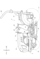
以下では、本発明に係る電動作業車の一例としてのトラクタについて説明する。図1に示すように、トラクタは、左右の前車輪10、左右の後車輪11、カバー部材12を備えている。 [Overall configuration of tractor]
A tractor as an example of an electric working vehicle according to the present invention will be described below. As shown in FIG. 1 , the tractor includes left and rightfront wheels 10 , left and right rear wheels 11 , and a cover member 12 .
以下では、本発明に係る電動作業車の一例としてのトラクタについて説明する。図1に示すように、トラクタは、左右の前車輪10、左右の後車輪11、カバー部材12を備えている。 [Overall configuration of tractor]
A tractor as an example of an electric working vehicle according to the present invention will be described below. As shown in FIG. 1 , the tractor includes left and right
トラクタは、機体フレーム2及び運転部3を備えている。機体フレーム2は、左右の前車輪10及び左右の後車輪11に支持されている。
The tractor has a body frame 2 and a driving section 3. The body frame 2 is supported by left and right front wheels 10 and left and right rear wheels 11 .
カバー部材12は、機体前部に配置されている。そして、運転部3は、カバー部材12の後方に設けられている。言い換えれば、カバー部材12は、運転部3の前方に配置されている。
The cover member 12 is arranged in the front part of the fuselage. The operating section 3 is provided behind the cover member 12 . In other words, the cover member 12 is arranged in front of the driving section 3 .
運転部3は、保護フレーム30、運転座席31、ステアリングホイール32を有している。オペレータは、運転座席31に着座可能である。これにより、オペレータは、運転部3に搭乗可能である。ステアリングホイール32の操作によって、左右の前車輪10は操向操作される。オペレータは、運転部3において、各種の運転操作を行うことができる。
The driving section 3 has a protective frame 30, a driver's seat 31, and a steering wheel 32. An operator can sit on the driver's seat 31 . This allows the operator to get on the driving section 3 . By operating the steering wheel 32, the left and right front wheels 10 are steered. The operator can perform various driving operations in the driving section 3 .
トラクタは、第一バッテリーとしての走行用バッテリー4を備えている。カバー部材12は、機体左右方向に沿う開閉軸芯Q周りに揺動可能に構成されている。これにより、カバー部材12は、開閉可能に構成されている。カバー部材12が閉状態であるとき、走行用バッテリー4は、カバー部材12に覆われている。
The tractor is equipped with a running battery 4 as a first battery. The cover member 12 is configured to be swingable around an opening/closing axis Q extending in the lateral direction of the machine body. Thereby, the cover member 12 is configured to be openable and closable. The driving battery 4 is covered with the cover member 12 when the cover member 12 is in the closed state.
図2に示すように、トラクタは、インバータ14及び電動モータMを備えている。走行用バッテリー4は、インバータ14へ電力を供給する。インバータ14は、走行用バッテリー4からの直流電力を交流電力に変換して電動モータMへ供給する。そして、電動モータMは、インバータ14から供給される交流電力により駆動する。
As shown in FIG. 2, the tractor includes an inverter 14 and an electric motor M. The running battery 4 supplies power to the inverter 14 . Inverter 14 converts the DC power from running battery 4 into AC power and supplies it to electric motor M. As shown in FIG. The electric motor M is driven by AC power supplied from the inverter 14 .
図2及び図3に示すように、トラクタは、静油圧式無段変速機15及びトランスミッション16を備えている。図3に示すように、静油圧式無段変速機15は、油圧ポンプ15a及び油圧モータ15bを有している。
As shown in FIGS. 2 and 3, the tractor includes a hydrostatic continuously variable transmission 15 and a transmission 16. As shown in FIG. 3, the hydrostatic continuously variable transmission 15 has a hydraulic pump 15a and a hydraulic motor 15b.
油圧ポンプ15aは、電動モータMからの回転動力により駆動する。油圧ポンプ15aが駆動することにより、油圧モータ15bから回転動力が出力される。尚、静油圧式無段変速機15は、油圧ポンプ15aと油圧モータ15bとの間で回転動力が変速されるように構成されている。静油圧式無段変速機15は、変速比を無段階に変更可能に構成されている。
The hydraulic pump 15a is driven by rotational power from the electric motor M. Rotational power is output from the hydraulic motor 15b by driving the hydraulic pump 15a. The hydrostatic continuously variable transmission 15 is configured such that the rotational power is changed between the hydraulic pump 15a and the hydraulic motor 15b. The hydrostatic continuously variable transmission 15 is configured so that the gear ratio can be changed steplessly.
油圧モータ15bから出力された回転動力は、トランスミッション16に伝達される。トランスミッション16に伝達された回転動力は、トランスミッション16の有するギヤ式変速機構によって変速され、左右の前車輪10及び左右の後車輪11へ分配される。これにより、左右の前車輪10及び左右の後車輪11が駆動する。
The rotational power output from the hydraulic motor 15b is transmitted to the transmission 16. The rotational power transmitted to the transmission 16 is changed in speed by a gear transmission mechanism of the transmission 16 and distributed to the left and right front wheels 10 and the left and right rear wheels 11 . As a result, the left and right front wheels 10 and the left and right rear wheels 11 are driven.
図2及び図3に示すように、トラクタは、ミッドPTO軸17及びリヤPTO軸18を備えている。電動モータMから出力された回転動力は、油圧ポンプ15a、ミッドPTO軸17、リヤPTO軸18へ分配される。これにより、ミッドPTO軸17及びリヤPTO軸18が回転する。
As shown in FIGS. 2 and 3, the tractor has a mid PTO shaft 17 and a rear PTO shaft 18. Rotational power output from the electric motor M is distributed to the hydraulic pump 15a, the mid PTO shaft 17, and the rear PTO shaft 18. Thereby, the mid PTO shaft 17 and the rear PTO shaft 18 rotate.
ミッドPTO軸17又はリヤPTO軸18に作業装置が接続されていれば、ミッドPTO軸17又はリヤPTO軸18の回転動力により、作業装置が駆動することとなる。例えば、図2に示すように、本実施形態では、ミッドPTO軸17に草刈装置19が接続されている。ミッドPTO軸17の回転動力により、草刈装置19が駆動する。
If a working device is connected to the mid PTO shaft 17 or the rear PTO shaft 18, the rotating power of the mid PTO shaft 17 or the rear PTO shaft 18 drives the working device. For example, as shown in FIG. 2, a mower 19 is connected to the mid PTO shaft 17 in this embodiment. The rotary power of the mid PTO shaft 17 drives the lawn mower 19 .
〔モータの制御に係る構成〕
図4に示すように、電動モータMの制御に係る構成は、アクセル装置33と、電動モータMの作動を制御する制御装置34と、インバータ14と、を備えている。アクセル装置33は、ステアリングホイール32の近傍に備えられている。アクセル装置33は、図示はしないが、揺動操作可能なレバーと、レバーの揺動操作によって操作されるポテンショメータとを備えている。アクセル装置33は制御装置34と接続されている。制御装置34は、信号用ハーネス35を介してインバータ14と接続されている。制御装置34は、アクセル装置33の指令に応じて、インバータ14に指令するように構成されている。インバータ14は、制御装置34の指令に応じて、走行用バッテリー4から電動モータMに供給される電力を調整して電動モータMの出力を制御するように構成されている。 [Configuration related to motor control]
As shown in FIG. 4 , the configuration related to control of the electric motor M includes anaccelerator device 33 , a control device 34 that controls the operation of the electric motor M, and an inverter 14 . The accelerator device 33 is provided near the steering wheel 32 . Although not shown, the accelerator device 33 includes a swingable lever and a potentiometer operated by swinging the lever. The accelerator device 33 is connected with the control device 34 . The control device 34 is connected to the inverter 14 via a signal harness 35 . The control device 34 is configured to issue a command to the inverter 14 according to a command from the accelerator device 33 . The inverter 14 is configured to control the output of the electric motor M by adjusting the electric power supplied from the battery 4 for running to the electric motor M according to a command from the control device 34 .
図4に示すように、電動モータMの制御に係る構成は、アクセル装置33と、電動モータMの作動を制御する制御装置34と、インバータ14と、を備えている。アクセル装置33は、ステアリングホイール32の近傍に備えられている。アクセル装置33は、図示はしないが、揺動操作可能なレバーと、レバーの揺動操作によって操作されるポテンショメータとを備えている。アクセル装置33は制御装置34と接続されている。制御装置34は、信号用ハーネス35を介してインバータ14と接続されている。制御装置34は、アクセル装置33の指令に応じて、インバータ14に指令するように構成されている。インバータ14は、制御装置34の指令に応じて、走行用バッテリー4から電動モータMに供給される電力を調整して電動モータMの出力を制御するように構成されている。 [Configuration related to motor control]
As shown in FIG. 4 , the configuration related to control of the electric motor M includes an
〔充電に係る構成〕
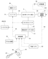
図4に示すように、走行用バッテリー4は外部の給電装置KDにより充電可能である。トラクタには、給電装置KDの給電用コネクタ36が接続可能な充電用接続部37が備えられている。充電用接続部37は、カバー部材12の内部に備えられ、カバー部材12を揺動開放すると、外方に露出する。制御装置34は、電動モータMの作動を制御するとともに、給電装置KDによる充電状態を制御する。 [Configuration related to charging]
As shown in FIG. 4, the runningbattery 4 can be charged by an external power supply device KD. The tractor is provided with a charging connection portion 37 to which a power supply connector 36 of the power supply device KD can be connected. The charging connection portion 37 is provided inside the cover member 12 and is exposed to the outside when the cover member 12 is opened by swinging. The control device 34 controls the operation of the electric motor M and also controls the charging state of the power supply device KD.
図4に示すように、走行用バッテリー4は外部の給電装置KDにより充電可能である。トラクタには、給電装置KDの給電用コネクタ36が接続可能な充電用接続部37が備えられている。充電用接続部37は、カバー部材12の内部に備えられ、カバー部材12を揺動開放すると、外方に露出する。制御装置34は、電動モータMの作動を制御するとともに、給電装置KDによる充電状態を制御する。 [Configuration related to charging]
As shown in FIG. 4, the running
充電用接続部37は、一般的に使用される標準的な規格に準拠したものである。給電用コネクタ36が充電用接続部37に接続された状態で、電力供給線39を介して走行用バッテリー4に対する充電が行われる。走行用バッテリー4は、電力供給線39を介して高電圧(例えば、数十ボルト~数百ボルト)の電力を、インバータ14、電動モータMに供給する。
The charging connection 37 complies with commonly used standards. The running battery 4 is charged through the power supply line 39 while the power supply connector 36 is connected to the charging connection portion 37 . The running battery 4 supplies high voltage (for example, several tens of volts to several hundred volts) power to the inverter 14 and the electric motor M through the power supply line 39 .
走行用バッテリー4は、例えば、リチウムイオンバッテリーを用いて構成され、図示はしないが、低電圧の小型の単位電池(セル)を多数積層した状態で構成され、外側が収納ケースによって密閉状態で覆われて収納されている。
The running battery 4 is configured using, for example, a lithium ion battery, and although not shown, is configured by stacking a large number of low-voltage small unit cells (cells), and the outside is covered with a storage case in a sealed state. It's packed away.
トラクタには、走行用バッテリー4の他に、制御装置34及びその他の電装品に電力を供給する第二バッテリーとしての電装品用バッテリー41が備えられている。電装品用バッテリー41は、電装品を駆動するために低電圧(12ボルト)の電力を供給する。電装品用バッテリー41は、DC/DCコンバータ(電圧変換器)42を介して走行用バッテリー4から供給される電力にて充電される。DC/DCコンバータ42は、走行用バッテリー4と電装品用バッテリー41との間で電圧値を調整しながら電力を供給可能である。すなわち、電力を供給して充電可能である。
The tractor is equipped with an electrical component battery 41 as a second battery that supplies power to the control device 34 and other electrical components in addition to the running battery 4 . The electrical component battery 41 supplies low voltage (12 volts) power to drive the electrical components. The electrical component battery 41 is charged with electric power supplied from the running battery 4 via a DC/DC converter (voltage converter) 42 . The DC/DC converter 42 can supply electric power while adjusting the voltage value between the running battery 4 and the electrical component battery 41 . That is, it can be charged by supplying electric power.
運転部3に、制御装置34を動作可能状態と非作動状態とに切り換え可能な始動指令手段としての切換操作部44が備えられている。切換操作部44は、持ち運び可能な操作キー45が差し込み装着可能な被装着部としての差し込み部46と、手動にて押し操作可能な押しボタン式のスイッチ47とを備えている。操作キー45が差し込み部46に差し込み装着された状態で、スイッチ47が押し操作されることにより、制御装置34を非作動状態から動作可能状態に切り換えることができる。操作キー45は、一般的な車両用のキーと同様に、当該作業車でのみ識別可能な鍵として機能するものである。
The operating section 3 is provided with a switching operation section 44 as a start command means capable of switching the control device 34 between an operable state and a non-operating state. The switching operation unit 44 includes an insertion portion 46 as a mounted portion into which a portable operation key 45 can be inserted, and a push button type switch 47 that can be manually pushed. By pushing the switch 47 while the operation key 45 is inserted into the insertion portion 46, the control device 34 can be switched from the non-operating state to the operable state. The operation key 45 functions as a key identifiable only in the work vehicle, like a general vehicle key.
操作パネル43には、例えば、車体の走行状態、作業状態、バッテリーの情報(充電量や温度)等を表示するメータパネル48が備えられている。メータパネル48は、制御装置34に接続され、制御装置34にて作動が制御されている。
The operation panel 43 is provided with a meter panel 48 that displays, for example, the vehicle's running state, work state, battery information (charge amount and temperature), and the like. The meter panel 48 is connected to the control device 34 and its operation is controlled by the control device 34 .
制御装置34、インバータ14、走行用バッテリー4、DC/DCコンバータ42、メータパネル48、及び、充電用接続部37等は、CAN(Controller Area Network)方式の信号用ハーネス35を介してデータを通信可能に接続されている。制御装置34は、充電通信用ハーネス49を介して充電用接続部37との間で通信が行われ、給電用コネクタ36が充電用接続部37に接続されているか否かについての情報、及び、作業車側で必要とされる充電電流の情報等が伝達される。充電用接続部37と給電装置KDとの間でも信号が通信可能に構成されている。又、制御装置34に切換操作部44の操作情報が入力される。
The control device 34, the inverter 14, the running battery 4, the DC/DC converter 42, the meter panel 48, the charging connector 37, etc. communicate data via a CAN (Controller Area Network) signal harness 35. connected as possible. The control device 34 communicates with the charging connection portion 37 via the charging communication harness 49, and receives information as to whether or not the power supply connector 36 is connected to the charging connection portion 37, and Information such as the charging current required by the work vehicle is transmitted. Signals are also configured to be communicable between the charging connection portion 37 and the power supply device KD. Further, operation information of the switching operation unit 44 is input to the control device 34 .
制御装置34は、給電用コネクタ36が充電用接続部37に接続されている状態で、操作キー45が差し込み部46に差し込み装着されると、充電モードに切り換わり、給電装置KDにより走行用バッテリー4への充電を行うことができる。
When the operation key 45 is inserted into the insertion portion 46 while the power supply connector 36 is connected to the charging connection portion 37, the control device 34 switches to the charging mode, and the driving battery is charged by the power supply device KD. 4 can be charged.
制御装置34は、操作キー45が差し込み部46に差し込み装着されている状態で、スイッチ47が押し操作されると、電動モータMを動作可能な動作可能状態に切り換わる。制御装置34は、操作キー45が差し込み部46から取り外された状態に切り換わると、電動モータMの作動制御を行わない非作動状態に切り換わるように構成されている。
When the switch 47 is pushed while the operation key 45 is inserted into the insertion portion 46, the control device 34 switches the electric motor M to an operable state. The control device 34 is configured to switch to a non-operating state in which operation control of the electric motor M is not performed when the operating key 45 is switched to the state in which it is removed from the insertion portion 46 .
制御装置34は、非作動状態においても、設定周期毎に繰り返し、走行用バッテリー4からの電力により電装品用バッテリー41を充電するようにDC/DCコンバータ42の作動を制御するインターバル充電処理を実行するように構成されている。
The control device 34 executes interval charging processing that controls the operation of the DC/DC converter 42 so as to charge the electric component battery 41 with electric power from the driving battery 4 repeatedly at a set cycle even in a non-operating state. is configured to
以下、図5のフローチャートを参照しながら制御装置34の制御について説明する。
当該作業車にて作業を行う場合には、オペレータにより運転部3の操作パネル43に備えられた切換操作部44において、操作キー45が差し込み部46に差し込み装着される。そのとき、給電装置KDの給電用コネクタ36が充電用接続部37に接続されていれば、走行用バッテリーに対する充電処理を実行する(ステップ♯1、♯2、♯3)。 The control of thecontrol device 34 will be described below with reference to the flowchart of FIG.
When the work vehicle is used for work, the operator inserts the operation key 45 into theinsertion portion 46 of the switching operation portion 44 provided on the operation panel 43 of the driving portion 3 . At that time, if the power feeding connector 36 of the power feeding device KD is connected to the charging connection portion 37, the running battery is charged (steps # 1, #2, #3).
当該作業車にて作業を行う場合には、オペレータにより運転部3の操作パネル43に備えられた切換操作部44において、操作キー45が差し込み部46に差し込み装着される。そのとき、給電装置KDの給電用コネクタ36が充電用接続部37に接続されていれば、走行用バッテリーに対する充電処理を実行する(ステップ♯1、♯2、♯3)。 The control of the
When the work vehicle is used for work, the operator inserts the operation key 45 into the
充電処理においては、給電装置KDに対して給電を行うように充電通信用ハーネス49を介して必要な情報を送信して、給電装置KDによる走行用バッテリー4に対する充電作動を開始する。そして、走行用バッテリー4が予め設定されている充電状態まで充電が行われ、満充電状態になると充電を停止する。
In the charging process, necessary information is transmitted via the charging communication harness 49 so as to supply power to the power supply device KD, and charging of the driving battery 4 by the power supply device KD is started. Then, the running battery 4 is charged to a preset charging state, and when it reaches the fully charged state, the charging is stopped.
給電用コネクタ36が充電用接続部37に接続されていない状態で、スイッチ47が押し操作されると、電動モータMを動作可能な動作可能状態に切り換わる(ステップ♯04)。そして、詳述はしないが、オペレータによる操作指令に基づいて電動モータMの作動を制御する(ステップ♯05)。尚、この電動モータMの作動制御において、スイッチ47が再度押し操作されると、電動モータMの作動を停止させることができる。
When the switch 47 is pushed while the power supply connector 36 is not connected to the charging connection portion 37, the electric motor M is switched to an operable state (step #04). Although not described in detail, the operation of the electric motor M is controlled based on the operation command from the operator (step #05). In this operation control of the electric motor M, when the switch 47 is pressed again, the operation of the electric motor M can be stopped.
当該作業車による作業が終了したのち、オペレータが操作キー45を差し込み部46から抜き外すことになるが、操作キー45が抜き外されると、制御装置34は、電動モータMの作動制御を行わない非作動状態に切り換わる(ステップ♯06、♯07)。非作動状態に切り換わると、後述するインターバル充電処理のみを実行可能な省電力モードに切り換わる。省電力モードは、電動モータMを作動させて作業を行う通常電力モードに比べて消費電力が少ない状態となる。
After the work by the working vehicle is completed, the operator pulls out the operation key 45 from the insertion portion 46. When the operation key 45 is pulled out, the control device 34 controls the operation of the electric motor M. It is switched to a non-operating state (steps # 06, #07). When it switches to the non-operating state, it switches to a power saving mode in which only the interval charging process, which will be described later, can be executed. In the power saving mode, power consumption is less than in the normal power mode in which the electric motor M is operated to perform work.
非作動状態に切り換わると、設定周期毎に繰り返し、走行用バッテリー4からの電力により電装品用バッテリー41を充電するように、DC/DCコンバータ42の作動を制御するインターバル充電処理を実行する。
After switching to the non-operating state, interval charging processing is executed to control the operation of the DC/DC converter 42 so as to charge the electric component battery 41 with the electric power from the running battery 4 repeatedly at a set cycle.
すなわち、非作動状態に切り換わると、タイマーカウントを開始し(ステップ♯08)、タイマーカウント時間が設定時間(設定周期に対応)に達すると、DC/DCコンバータ42の作動を制御して走行用バッテリー4からの電力により電装品用バッテリー41を充電する(ステップ♯10、♯11)。充電処理が終了すると、タイマーカウント値をリセットして(ステップ♯12)、再度、タイマーカウントを開始する。そして、ステップ♯08~ステップ♯12の処理が設定時間毎に繰り返し行われることになる。このステップ♯08、♯10、♯11、♯12の処理がインターバル充電処理に対応する。
That is, when the state is switched to the non-operating state, the timer count is started (step #08), and when the timer count reaches the set time (corresponding to the set period), the operation of the DC/DC converter 42 is controlled and the driving is performed. The electrical component battery 41 is charged with power from the battery 4 (steps # 10, #11). When the charging process is completed, the timer count value is reset (step #12) and the timer count is restarted. Then, the processing from step # 08 to step #12 is repeated every set time. The processes of steps # 08, #10, #11 and #12 correspond to the interval charging process.
インターバル充電処理を実行している途中で、操作キー45が差し込み部46に差し込み装着されると、初期状態(ステップ♯01)にリターンする(ステップ♯09)。尚、そのとき、省電力モードから通常電力モードに復帰することになる。その後は、走行用バッテリー4への充電処理、あるいは、電動モータMの作動制御を実行することができる。
When the operation key 45 is inserted into the insertion portion 46 while the interval charging process is being executed, the process returns to the initial state (step #01) (step #09). At that time, the power saving mode is returned to the normal power mode. After that, the process of charging the running battery 4 or controlling the operation of the electric motor M can be executed.
設定時間(設定周期)は、その周期内において充電が行われなくても充電量を確保することが可能な程度の長さに設定されている。例えば、1週間程度の長さに設定することができる。要するに、電装品用バッテリー41が放電して充電量が非常に少なくなるおそれがない程度の長さである。
The set time (set cycle) is set to a length that allows the amount of charge to be secured even if charging is not performed within that cycle. For example, it can be set to a length of about one week. In short, the length is such that there is no possibility that the electrical component battery 41 will be discharged and the amount of charge will become very small.
このようなインターバル充電処理を実行することにより、当該作業車が使用されない状態が長期間継続することがあっても、電装品用バッテリー41の充電量が非常に少なくなることを未然に回避して、走行用バッテリー4への充電を良好に行うことができる。
By executing such an interval charging process, even if the work vehicle is not used for a long period of time, it is possible to prevent the electrical component battery 41 from becoming very low in charge. , the driving battery 4 can be charged satisfactorily.
〔別実施形態〕
(1)上記実施形態では、制御装置34が、インターバル充電処理を実行するとともに、電動モータMの作動を制御する構成としたが、この構成に代えて、走行用バッテリー4や電装品用バッテリー41への充電処理を実行する第一の制御装置と、電動モータMの作動を制御する第二の制御装置とを各別に備えて、第一の制御装置がインターバル充電処理を実行するように構成されるものでもよい。 [Another embodiment]
(1) In the above embodiment, thecontrol device 34 executes the interval charging process and controls the operation of the electric motor M. and a second control device for controlling the operation of the electric motor M, and the first control device is configured to execute the interval charging process. Anything is fine.
(1)上記実施形態では、制御装置34が、インターバル充電処理を実行するとともに、電動モータMの作動を制御する構成としたが、この構成に代えて、走行用バッテリー4や電装品用バッテリー41への充電処理を実行する第一の制御装置と、電動モータMの作動を制御する第二の制御装置とを各別に備えて、第一の制御装置がインターバル充電処理を実行するように構成されるものでもよい。 [Another embodiment]
(1) In the above embodiment, the
(2)上記実施形態では、操作キー45が差し込み部46に差し込み装着可能に構成されるものを示したが、この構成に代えて、操作キー45が機体側の受信部との間で無線通信可能であり、操作キー45が車体に近接する状態でスイッチ47が操作されると、制御装置34が動作可能状態に切り換わる構成としてもよい。
(2) In the above embodiment, the operation keys 45 are configured to be insertable into the insertion portion 46. Alternatively, the control device 34 may be switched to the operable state when the switch 47 is operated while the operation key 45 is in proximity to the vehicle body.
(3)上記実施形態では、制御装置34は操作キー45が差し込み部46から取り外された状態に切り換わったのちは省電力モードに切り換わる構成としたが、この構成に代えて、操作キー45が差し込み部46から取り外された状態に切り換わったのちにおいても通常電力モードに維持される構成としてもよい。
(3) In the above embodiment, the control device 34 is configured to switch to the power saving mode after switching to the state in which the operation key 45 is removed from the insertion portion 46, but instead of this configuration, the operation key 45 The normal power mode may be maintained even after switching to the state in which is removed from the insertion portion 46 .
(4)上記実施形態では、制御装置34に電力を供給するバッテリーとして電装品用バッテリー41だけが備えられる構成としたが、この構成に代えて、図6に示すように、電装品用バッテリー41とは別に、何等かの理由により電装品用バッテリー41が作動しない場合等において使用可能な予備バッテリー50を備える構成としてもよい。
(4) In the above embodiment, only the electrical component battery 41 is provided as a battery for supplying power to the control device 34. Instead of this configuration, an electrical component battery 41 is provided as shown in FIG. Apart from this, it may be configured to include a spare battery 50 that can be used in the event that the electrical component battery 41 does not work for some reason.
本発明は、トラクタに限らず、田植機、コンバイン、建設機械等、種々の電動作業車に適用できる。
The present invention is applicable not only to tractors, but also to various electric working vehicles such as rice transplanters, combine harvesters, and construction machinery.
4 走行用バッテリー(第一バッテリー)
34 制御装置
41 電装品用バッテリー(第二バッテリー)
42 DC/DCコンバータ(電圧変換器)
43 制御装置
44 スイッチ(始動指令手段)
45 操作キー
46 差し込み部(被装着部)
KD 給電装置
M 電動モータ
4 Running battery (first battery)
34control device 41 battery for electrical equipment (second battery)
42 DC/DC converter (voltage converter)
43control device 44 switch (start command means)
45Operation key 46 Insertion part (mounted part)
KD Power supply device M Electric motor
34 制御装置
41 電装品用バッテリー(第二バッテリー)
42 DC/DCコンバータ(電圧変換器)
43 制御装置
44 スイッチ(始動指令手段)
45 操作キー
46 差し込み部(被装着部)
KD 給電装置
M 電動モータ
4 Running battery (first battery)
34
42 DC/DC converter (voltage converter)
43
45
KD Power supply device M Electric motor
Claims (5)
- 車体を走行駆動可能な電動モータと、
前記電動モータに駆動用電力を供給するとともに、外部の給電装置により充電可能な第一バッテリーと、
車体に搭載されている電装品に電力を供給するとともに、充電可能な第二バッテリーと、
前記第一バッテリーと前記第二バッテリーとの間で電圧値を調整しながら電力を供給可能な電圧変換器と、
前記第二バッテリーからの電力が供給されて、前記給電装置による充電状態を制御するとともに、前記電圧変換器の作動を制御する制御装置と、が備えられ、
前記制御装置は、設定周期毎に繰り返し、前記第一バッテリーからの電力により前記第二バッテリーを充電するように、前記電圧変換器の作動を制御するインターバル充電処理を実行する電動作業車。 an electric motor capable of driving the vehicle body;
a first battery that supplies drive power to the electric motor and is rechargeable by an external power supply device;
A second battery that supplies electric power to the electrical components mounted on the vehicle body and is rechargeable;
a voltage converter capable of supplying power while adjusting a voltage value between the first battery and the second battery;
a control device that is supplied with power from the second battery, controls the state of charge by the power supply device, and controls the operation of the voltage converter;
The electric utility vehicle, wherein the control device repeatedly performs an interval charging process for controlling the operation of the voltage converter so as to charge the second battery with electric power from the first battery. - 前記設定周期は、その周期内において充電が行われなくても充電量を確保することが可能な程度の長さに設定されている請求項1に記載の電動作業車。 The electric working vehicle according to claim 1, wherein the set period is set to a length that allows the amount of charge to be secured even if charging is not performed within the period.
- 前記制御装置は、前記電動モータの作動を制御するように構成され、
持ち運び可能な操作キーが車体に近接する状態、あるいは、前記操作キーが被装着部に装着された状態で、手動操作されることにより、前記制御装置を動作可能状態に切り換える始動指令手段、が備えられ、
前記制御装置は、前記操作キーが車体から離間する状態あるいは前記操作キーが前記被装着部から取り外された状態に切り換わると、前記電動モータの作動制御を行わない非作動状態に切り換わるように構成され、
前記制御装置は、前記非作動状態においても前記インターバル充電処理を実行可能に構成されている請求項1又は2に記載の電動作業車。 the controller is configured to control operation of the electric motor;
a start command means for switching the control device to an operable state by being manually operated in a state in which the portable operation key is close to the vehicle body or in a state in which the operation key is attached to the attachment portion; be
When the control device switches to a state in which the operation key is separated from the vehicle body or a state in which the operation key is removed from the mounted portion, the control device switches to a non-operating state in which operation control of the electric motor is not performed. configured,
The electric working vehicle according to claim 1 or 2, wherein the control device is configured to be able to execute the interval charging process even in the non-operating state. - 前記制御装置は、前記操作キーが車体から離間する状態あるいは前記操作キーが前記被装着部から取り外された状態に切り換わったのちは、前記インターバル充電処理のみを実行可能な省電力モードで作動するように構成されている請求項3に記載の電動作業車。 After switching to a state in which the operation key is separated from the vehicle body or a state in which the operation key is removed from the mounted portion, the control device operates in a power saving mode capable of executing only the interval charging process. The electric working vehicle according to claim 3, which is configured as follows.
- 前記第二バッテリーとは別に、前記制御装置に対して電力を供給可能な予備バッテリーが備えられている請求項1から4のいずれか1項に記載の電動作業車。
The electric working vehicle according to any one of claims 1 to 4, further comprising a spare battery capable of supplying power to the control device, separately from the second battery.
Applications Claiming Priority (2)
| Application Number | Priority Date | Filing Date | Title |
|---|---|---|---|
| JP2022015812A JP2023113438A (en) | 2022-02-03 | 2022-02-03 | electric work vehicle |
| JP2022-015812 | 2022-02-03 |
Publications (1)
| Publication Number | Publication Date |
|---|---|
| WO2023149047A1 true WO2023149047A1 (en) | 2023-08-10 |
Family
ID=87552156
Family Applications (1)
| Application Number | Title | Priority Date | Filing Date |
|---|---|---|---|
| PCT/JP2022/041914 WO2023149047A1 (en) | 2022-02-03 | 2022-11-10 | Electric work vehicle |
Country Status (2)
| Country | Link |
|---|---|
| JP (1) | JP2023113438A (en) |
| WO (1) | WO2023149047A1 (en) |
Citations (3)
| Publication number | Priority date | Publication date | Assignee | Title |
|---|---|---|---|---|
| JP2006050779A (en) * | 2004-08-04 | 2006-02-16 | Toyota Motor Corp | Motor driving device |
| JP2017128186A (en) * | 2016-01-19 | 2017-07-27 | 株式会社クボタ | Plug-in hybrid service vehicle |
| JP2021151030A (en) * | 2020-03-18 | 2021-09-27 | 本田技研工業株式会社 | Vehicle power supply system |
-
2022
- 2022-02-03 JP JP2022015812A patent/JP2023113438A/en active Pending
- 2022-11-10 WO PCT/JP2022/041914 patent/WO2023149047A1/en unknown
Patent Citations (3)
| Publication number | Priority date | Publication date | Assignee | Title |
|---|---|---|---|---|
| JP2006050779A (en) * | 2004-08-04 | 2006-02-16 | Toyota Motor Corp | Motor driving device |
| JP2017128186A (en) * | 2016-01-19 | 2017-07-27 | 株式会社クボタ | Plug-in hybrid service vehicle |
| JP2021151030A (en) * | 2020-03-18 | 2021-09-27 | 本田技研工業株式会社 | Vehicle power supply system |
Also Published As
| Publication number | Publication date |
|---|---|
| JP2023113438A (en) | 2023-08-16 |
Similar Documents
| Publication | Publication Date | Title |
|---|---|---|
| CN103370247B (en) | The charge-discharge controller of electric storage means and method, hybrid working machine | |
| CN103879400B (en) | The driving mode switch controller of motor vehicle driven by mixed power | |
| US20080234096A1 (en) | Hybrid Utility Vehicle | |
| CA2314059A1 (en) | Control system for a hybrid vehicle | |
| WO2023149047A1 (en) | Electric work vehicle | |
| EP1283132A3 (en) | Electronic apparatus, drive mechanism and drive control method for a front panel | |
| KR101006185B1 (en) | Electric working device for agriculture | |
| CN112449816B (en) | Range extender, hybrid rice transplanter and working method of hybrid rice transplanter | |
| JP6628616B2 (en) | Plug-in hybrid working vehicle | |
| JP2023097969A (en) | electric work vehicle | |
| JP2013005932A (en) | Fire engine | |
| CN210133015U (en) | Hybrid power tractor | |
| JP3786841B2 (en) | Self-propelled vehicle | |
| WO2023149026A1 (en) | Electric work vehicle | |
| JP2023097970A (en) | electric work vehicle | |
| WO2023127363A1 (en) | Electric work vehicle | |
| EP4331900A1 (en) | Electric work vehicle and charging method | |
| JP2018157665A (en) | Work vehicle | |
| WO2023149035A1 (en) | Electric work vehicle | |
| WO2024038627A1 (en) | Electric work vehicle | |
| WO2024029104A1 (en) | Electric work vehicle | |
| CN113107734B (en) | Engine starting system and starting method | |
| CN104691303B (en) | The energy control method of extended-range electric vehicle | |
| US20240059178A1 (en) | Electric work vehicle | |
| CN215038941U (en) | Loading drive control system of mixer truck |
Legal Events
| Date | Code | Title | Description |
|---|---|---|---|
| 121 | Ep: the epo has been informed by wipo that ep was designated in this application |
Ref document number: 22924952 Country of ref document: EP Kind code of ref document: A1 |