WO2023149042A1 - アンテナモジュール、アンテナシステム、及び電波受信方法 - Google Patents
アンテナモジュール、アンテナシステム、及び電波受信方法 Download PDFInfo
- Publication number
- WO2023149042A1 WO2023149042A1 PCT/JP2022/041397 JP2022041397W WO2023149042A1 WO 2023149042 A1 WO2023149042 A1 WO 2023149042A1 JP 2022041397 W JP2022041397 W JP 2022041397W WO 2023149042 A1 WO2023149042 A1 WO 2023149042A1
- Authority
- WO
- WIPO (PCT)
- Prior art keywords
- ports
- antenna
- antenna elements
- received
- linearly polarized
- Prior art date
- Legal status (The legal status is an assumption and is not a legal conclusion. Google has not performed a legal analysis and makes no representation as to the accuracy of the status listed.)
- Ceased
Links
Images








Classifications
-
- H—ELECTRICITY
- H01—ELECTRIC ELEMENTS
- H01Q—ANTENNAS, i.e. RADIO AERIALS
- H01Q3/00—Arrangements for changing or varying the orientation or the shape of the directional pattern of the waves radiated from an antenna or antenna system
- H01Q3/26—Arrangements for changing or varying the orientation or the shape of the directional pattern of the waves radiated from an antenna or antenna system varying the relative phase or relative amplitude of energisation between two or more active radiating elements; varying the distribution of energy across a radiating aperture
- H01Q3/267—Phased-array testing or checking devices
-
- H—ELECTRICITY
- H01—ELECTRIC ELEMENTS
- H01Q—ANTENNAS, i.e. RADIO AERIALS
- H01Q21/00—Antenna arrays or systems
- H01Q21/24—Combinations of antenna units polarised in different directions for transmitting or receiving circularly and elliptically polarised waves or waves linearly polarised in any direction
-
- H—ELECTRICITY
- H01—ELECTRIC ELEMENTS
- H01Q—ANTENNAS, i.e. RADIO AERIALS
- H01Q3/00—Arrangements for changing or varying the orientation or the shape of the directional pattern of the waves radiated from an antenna or antenna system
- H01Q3/26—Arrangements for changing or varying the orientation or the shape of the directional pattern of the waves radiated from an antenna or antenna system varying the relative phase or relative amplitude of energisation between two or more active radiating elements; varying the distribution of energy across a radiating aperture
- H01Q3/30—Arrangements for changing or varying the orientation or the shape of the directional pattern of the waves radiated from an antenna or antenna system varying the relative phase or relative amplitude of energisation between two or more active radiating elements; varying the distribution of energy across a radiating aperture varying the relative phase between the radiating elements of an array
Definitions
- the present invention relates to an antenna module, an antenna system, and a radio wave receiving method.
- Patent Document 1 discloses a technique for improving the axial ratio of a circularly polarized array antenna configured by arranging a plurality of circularly polarized antenna elements.
- the excitation phase of a plurality of circularly polarized antenna elements is obtained so as to equalize the radiated electric field strength of the three types of linearly polarized wave components, and the plurality of circularly polarized antenna elements are obtained at this phase.
- one antenna uses a circularly polarized antenna and the other antenna uses a linearly polarized wave.
- An antenna is used.
- a radio wave transmitted from a circularly polarized antenna generally does not become a perfect circularly polarized wave, but becomes an elliptically polarized wave.
- the receiving sensitivity varies depending on the major axis direction of the elliptically polarized wave.
- Still another object of the present invention is to provide an antenna system capable of suppressing a decrease in receiving sensitivity when linearly polarized waves are received by a circularly polarized wave receiving antenna.
- a plurality of antenna elements each including two ports for receiving two orthogonal linear polarizations;
- a processing unit that processes signals received by the plurality of antenna elements, The polarization directions of the linearly polarized waves received by the plurality of antenna elements through each of the two ports are different between the plurality of antenna elements,
- the processing unit compares reception levels of linearly polarized wave components received at each of the plurality of ports included in the plurality of antenna elements when radio waves arrive, among the plurality of ports, and determines that the reception level is the highest.
- An antenna module for high port detection is provided.
- a plurality of antenna elements each having two ports for transmitting and receiving two linearly polarized waves with different polarization directions through the two ports; and supplying transmission signals to the plurality of antenna elements, a first antenna module having a processing unit for processing a received signal; a second antenna module that receives radio waves transmitted from the first antenna module, measures a reception level, and returns a signal including information specifying the measured reception level to the first antenna module;
- the polarization directions of the linearly polarized waves transmitted by the plurality of antenna elements are different among the antenna elements
- the processing unit is a process of supplying a transmission signal to one of the plurality of ports of the plurality of antenna elements to transmit a linearly polarized wave and receiving a return signal returned from the second antenna module; for each of the An antenna system is provided for detecting the port used when the reception level is the highest among the plurality of ports from the information specifying the reception level contained in the return signal.
- FIG. 1 is a schematic diagram of an antenna module according to a first embodiment.
- FIG. 2 is a flow chart showing the procedure of processing executed by the processing unit of the antenna module according to the first embodiment.
- FIG. 3A is a schematic diagram showing the trajectory of the tip of the electric field vector on the xy plane of the elliptical polarization received by the two antenna elements, and FIG. It is a diagram showing the relationship with the maximum port.
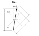
- FIG. 4 is a schematic diagram showing the trajectory of the tip of the electric field vector on the xy plane of the linearly polarized waves received by the two antenna elements of the antenna module according to the modification of the first embodiment.
- FIG. 5 is a plan view of two antenna elements mounted on an antenna module according to another modification of the first embodiment.
- FIG. 6 is a schematic diagram of an antenna module according to a second embodiment.
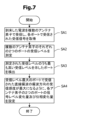
- FIG. 7 is a flow chart showing the procedure of processing executed by the processing unit of the antenna module according to the second embodiment.
- FIG. 8 is a schematic diagram for explaining polarization directions of two antenna elements of the antenna module according to the second embodiment.
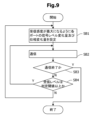
- FIG. 9 is a flow chart showing the processing procedure of the processing section of the antenna module according to the second embodiment.
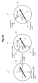
- FIG. 10 is a schematic diagram showing the relationship between the antenna element of the antenna module according to the modification of the second embodiment and its polarization direction.
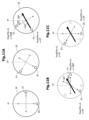
- FIG. 11A is a schematic diagram showing the relationship between the antenna element of an antenna module according to another modification of the second embodiment and its polarization direction, and
- FIGS. 2 is a schematic diagram showing the antenna elements of .
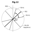
- FIG. 12 is a schematic diagram showing the positional relationship of the polarization directions of linearly polarized waves received at 2N ports when N antenna elements are stacked.
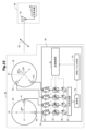
- FIG. 13 is a schematic diagram of an antenna system according to a third embodiment.
- FIG. 14 is a flow chart showing the procedure of processing of the first antenna module and the second antenna module of the antenna system according to the third embodiment.
- FIG. 15 is a schematic diagram of an antenna system according to a modification of the third embodiment.
- Figures 16A to 16D are schematic diagrams of communication systems using antenna modules according to the embodiments described above.
- FIG. 1 is a schematic diagram of an antenna module according to a first embodiment.
- the antenna module according to the first embodiment comprises two antenna elements 20 and a processing section 30 .
- Two antenna elements 20 receive radio waves transmitted from the transmitting antenna 72 .
- the transmitting antenna 72 is designed to transmit circularly polarized waves, the actually transmitted radio waves are not perfectly circularly polarized, but elliptically polarized 80 .
- Each of the two antenna elements 20 is, for example, a circular patch antenna and has two ports.
- the two ports of one antenna element 20 are denoted as ports P0 and P1, and the two ports of the other antenna element 20 are denoted as ports P2 and P3.
- Linearly polarized waves can be received by each of the two ports of antenna element 20 .
- An xyz orthogonal coordinate system is defined in which the plane on which the two antenna elements 20 are arranged is the xy plane.
- the angle of inclination clockwise from the positive direction of the y-axis is denoted as an inclination angle ⁇ .
- the value of the tilt angle ⁇ is negative when tilted counterclockwise from the positive direction of the y-axis.
- the polarization direction of the linearly polarized wave received at the port P0 of one antenna element 20 is parallel to the y-axis (tilt angle ⁇ is 0°), and the polarization direction of the linearly polarized wave received at the port P1 is parallel to the x-axis. It is parallel (inclination angle ⁇ is 90°).
- the inclination angle ⁇ of the polarization direction of the linearly polarized wave received at the port P2 of the other antenna element 20 is 135°, and the inclination angle ⁇ of the polarization direction of the linearly polarized wave received at the port P3 is 45°.
- the polarization directions of the linearly polarized waves received at one port and the linearly polarized waves received at the other port are orthogonal to each other. Furthermore, the polarization directions of the two linearly polarized waves received by each of the two ports of one antenna element 20 and the polarization directions of the two linearly polarized waves received by each of the two ports of the other antenna element 20 form an angle of 45°.
- the processing unit 30 includes four receivers 31 and a reception level comparison determination unit 32.
- the four receivers 31 are connected to a total of four ports P0, P1, P2, P3 of the two antenna elements 20, respectively. Received signals received at four ports P0, P1, P2, and P3 are input to four receivers 31, respectively. Receiver 31 measures the reception level of the received signal. The reception level measured by the receiver 31 corresponds to the strength of the linearly polarized wave component received at each port. A reception level measurement result is input to the reception level comparison/determination unit 32 .
- FIG. 2 is a flowchart showing a procedure (radio wave reception method) of processing executed by the processing unit 30.
- the radio waves transmitted from the transmitting antenna 72 (FIG. 1) are received by the two antenna elements 20, and the received signals received by the four ports P0, P1, P2, and P3 are sent to the receiver of the processing unit 30.
- 31 obtains (step SA1).
- Receiver 31 measures the reception levels of the reception signals received at each of the four ports P0, P1, P2 and P3 (step SA2).
- a reception level measurement result is input to the reception level comparison/determination unit 32 .
- the reception level comparison/determination unit 32 compares the reception levels of the reception signals received by the ports P0, P1, P2, and P3, and detects the port with the highest reception level (step SA3).
- FIG. 3A is a schematic diagram showing a locus 81 of the tip of the electric field vector on the xy plane of the elliptically polarized waves received by the two antenna elements 20 (FIG. 1). Even if the transmit antenna 72 (FIG. 1) is designed to transmit circularly polarized waves, the actual transmitted radio waves will generally be elliptically polarized.
- FIG. 3A shows an example in which the major axis MA of the elliptically polarized wave is slightly inclined with respect to the y-axis direction.
- Ports P0 and P1 of one antenna element 20 receive linearly polarized waves having polarization directions parallel to the y-direction and x-direction, respectively. correspond to the y-direction dimension and the x-direction dimension of the locus 81, respectively.
- Ports P2 and P3 of the other antenna element 20 receive linearly polarized waves with inclination angles ⁇ of 135° and 45°, respectively.
- L3 corresponds to the dimension of the locus 81 in the direction D135 with an inclination angle ⁇ of 135° and the direction D45 with an inclination angle ⁇ of 45°.
- the magnitude relationship of the reception levels L0, L1, L2, and L3 is L0>L3>L2> becomes L1.
- the direction of polarization (y-direction) of the linearly polarized wave received at port P0 which exhibits the highest received level, is compared to the direction of polarization of the linearly polarized waves received at the other ports P1, P2, and P3. closest in the direction of the long axis MA of the wave.
- FIG. 3B is a diagram showing the relationship between the direction of the major axis MA of the elliptically polarized wave and the port with the maximum reception level.
- the reception level L0 is the maximum, it can be specified that the tilt angle ⁇ of the major axis MA of the elliptically polarized wave is greater than ⁇ 22.5° and less than 22.5°.
- the reception level L3 is the maximum, it can be specified that the tilt angle ⁇ of the major axis MA of the elliptically polarized wave is greater than 22.5° and less than 67.5°.
- the tilt angle ⁇ of the major axis MA of the elliptically polarized wave is greater than 67.5° and less than 112.5°.
- the reception level L2 is maximum, it can be specified that the tilt angle ⁇ of the major axis MA of the elliptically polarized wave is greater than 112.5° and less than 157.5°.
- the tilt angle ⁇ of the major axis MA of the elliptical polarized wave can be specified within a certain range, it is possible to optimize the processing in various processes depending on the direction of the major axis MA of the elliptical polarized wave.
- two antenna elements 20 receive elliptically polarized waves, but in the modified example of the first embodiment, linearly polarized waves are received. In this modification, the direction of polarization of the incoming linearly polarized wave is estimated.
- FIG. 4 is a schematic diagram showing the locus 81 of the tip of the electric field vector on the xy plane of the linearly polarized waves received by the two antenna elements 20 (FIG. 1) of the antenna module according to the modification of the first embodiment.
- the trajectory 81 is, for example, a straight line extending in a direction slightly deviated from the y-axis direction.
- the reception levels L0 and L1 of the reception signals received at the ports P0 and P1 (FIG. 1) of one antenna element 20 correspond to the y-direction dimension and x-direction dimension of the locus 81, respectively.
- the reception levels L2 and L3 of the reception signals received at the ports P2 and P3 of the other antenna element 20 are the dimensions of the direction D135 with an inclination angle ⁇ of 135° and the direction D45 with an inclination angle ⁇ of 45° of the locus 81, respectively. corresponds to
- the polarization direction of the incoming linearly polarized wave can be set within a certain range from the magnitude relationship of the reception levels L0, L1, L2, and L3 of the reception signals received at the four ports P0, P1, P2, and P3. can be specified.
- FIG. 5 is a plan view of two antenna elements 20 mounted on an antenna module according to another modification of the first embodiment.
- a circular patch antenna is used as the antenna element 20 in the antenna module according to the first embodiment.
- a square patch antenna is used as the antenna element 20 .
- the two ports of each antenna element 20 are arranged on a line segment whose ends are the midpoints of two adjacent sides of the antenna element 20 and the geometric center.
- the polarization directions of the linearly polarized waves received by the two antenna elements 20 are shifted by 45° between the two antenna elements 20 .
- the antenna element 20 is circular, even if the polarization direction of the antenna element 20 is rotated, the outer shape of the antenna element 20 does not appear to rotate.
- the antenna element 20 is square as in the modification shown in FIG. There is a need.
- the shape of the antenna element 20 may be square as in this modified example. Further, the antenna element 20 may have other shapes under the condition that the antenna element 20 can receive two linearly polarized waves having polarization directions orthogonal to each other. For example, a square shape may be formed by cutting off the four corners of a square.
- the polarization directions of the linearly polarized waves received by the two antenna elements 20 form an angle of 45° between the antenna elements 20.
- the angle formed by the polarization directions of the linearly polarized waves does not necessarily have to be 45°.
- a total of four ports P0, P1, P2, and P3 of the two antenna elements 20 may be configured to receive four linearly polarized waves with different polarization directions.
- the amount of signal level change (gain and attenuation) at each port should be adjusted so that the reception sensitivity in the polarization direction of the linearly polarized wave received at the port with the maximum reception level of the incoming radio wave is maximized. ) and the amount of phase change may be set.
- FIG. 6 is a schematic diagram of an antenna module according to the second embodiment.
- the antenna module according to the second embodiment also has two antenna elements 20 and a processing section 30, like the antenna module according to the first embodiment.
- the processing section 30 includes four receivers 31 and a reception level comparison/determination section 32 .
- the processing unit 30 in addition to the receiver 31 and the reception level comparison/determination unit 32, includes a reception amplifier 33, a transmission amplifier 34, a variable attenuator 35, a phase shifter 36, and a composite demultiplexer. vessel 37.
- a reception amplifier 33, a transmission amplifier 34, a variable attenuator 35, and a phase shifter 36 are provided corresponding to each of the four ports P0, P1, P2, and P3.
- the connection order of the reception amplifier 33, the transmission amplifier 34, the variable attenuator 35, and the phase shifter 36 is not limited to the order shown in FIG.
- the reception level comparison/determination unit 32 controls the gain amount of the reception amplifier 33, the attenuation amount of the variable attenuator 35, and the phase change amount of the phase shifter 36. By controlling the gain of the receiving amplifier 33 and the attenuation of the variable attenuator 35, the signal level variation of the received signal is controlled.
- the received signal received at each of the four ports P0, P1, P2, P3 is amplified by the receiving amplifier 33 and passed through the variable attenuator 35 and the phase shifter 36. input to the demultiplexer 37. Synthesizer 37 synthesizes the four input received signals. The combined received signal is down-converted and input to the baseband signal processing circuit.
- the signal to be transmitted is demultiplexed into four signals by the demultiplexer 37.
- Each demultiplexed signal passes through the phase shifter 36 and the variable attenuator 35, is amplified by the transmission amplifier 34, and is supplied to each of the four ports P0, P1, P2 and P3.
- the gain of the transmission amplifier 34, the amount of attenuation of the variable attenuator 35, and the amount of phase change of the phase shifter 36 are controlled.
- FIG. 7 is a flowchart showing a procedure of processing (radio wave reception method) executed by the processing unit 30.
- the procedure from step SA1 to step SA3 is the same as the procedure (FIG. 2) executed by the processing unit 30 of the antenna module according to the first embodiment.
- step SA3 if there are a plurality of ports showing the highest reception level, any one port may be set as the port with the highest reception level. Alternatively, a priority may be given to each port in advance, and the port with the highest priority among a plurality of ports exhibiting the highest reception level may be set as the port with the highest reception level.
- step SA3 when the port showing the highest reception level is detected, two antennas are installed so that the reception sensitivity in the direction of polarization of the linearly polarized wave received at the port with the maximum reception level is maximized.
- the amount of signal level change and the amount of phase change to be applied to the reception signals received at the respective two ports of element 20 are set (step SA4).
- the amount of signal level change and the amount of phase change applied to the received signal received at each port may be referred to as the amount of signal level change of the port and the amount of phase change of the port.
- the gain amount of the receiving amplifier 33 (FIG. 6) connected to each port
- the attenuation amount of the variable attenuator 35 (FIG.
- the phase shift amount of the phase shifter 36 (FIG. 6) are set. do.
- the signal level of the received signal received at each port changes by the set signal level change amount
- the phase of the received signal changes by the set phase change amount
- the demultiplexer 37 is entered.
- the signal level of the reception signal received at each port is adjusted so that the reception sensitivity in the polarization direction of the linearly polarized wave received at the port with the maximum reception level is maximized.
- An example of controlling the amount of change and the amount of phase change will be described.
- FIG. 8 is a schematic diagram for explaining the polarization directions of the two antenna elements 20 of the antenna module according to the second embodiment.
- Ports P0 and P1 of one antenna element 20 are arranged at positions with inclination angles ⁇ of 180° and 90°, respectively.
- the tilt angle ⁇ of the polarization direction of the linearly polarized wave received at the port P0 is 0°
- the tilt angle ⁇ of the polarization direction of the linearly polarized wave received at the port P1 is 90°.
- the port P2 and port P3 of the other antenna element 20 are arranged at positions where the tilt angles ⁇ are ⁇ 45° and ⁇ 135°, respectively.
- the tilt angle ⁇ of the polarization direction of the linearly polarized wave received at the port P2 is 135°
- the tilt angle ⁇ of the polarization direction of the linearly polarized wave received at the port P3 is 45°.
- each port is configured to maximize the reception sensitivity of the linearly polarized wave with the tilt angle ⁇ of the polarization direction of 0°. to control the amount of signal level change and the amount of phase change.
- the thick arrow indicates the polarization direction when the tilt angle ⁇ is 0°.
- the transmission rate will be used for explanation. Letting the power of the input signal of the receiving amplifier 33 be Pin and the power of the output signal of the variable attenuator 35 be Pout, the pass rate is defined as Pout/Pin.
- the phase of port P0 is used as a reference for the phase change amounts of other ports P1, P2, and P3. That is, the phases of the ports P1, P2, and P3 are specified by the phase change amount ⁇ based on the phase of the port P0.
- the control in the antenna element 20 provided with the ports P2 and P3 will be explained. If the transmission rate of port P2 is set to G and the amount of phase change ⁇ is set to 180°, and the transmission rate of port P3 is set to G and the amount of phase change ⁇ is set to 0°, a straight line with an inclination angle ⁇ of 0° in the polarization direction Receiving sensitivity for polarized waves is maximized. Furthermore, with this setting, the phases of the linearly polarized received signals received by the two antenna elements 20 can be matched.
- FIG. 9 is a flow chart showing the processing procedure (radio wave reception method) of the processing unit 30 (FIG. 6).
- the processing unit 30 determines whether or not the reception level of the received signal combined by the combiner/demultiplexer 37 (FIG. 6) is equal to or higher than the determination threshold (steps SB3 and SB4). If the reception level is equal to or higher than the determination threshold, communication is continued (steps SB4 and SB2). When the reception level becomes less than the determination threshold, the signal level change amount and the phase change amount ⁇ of each port are reset so as to maximize the reception sensitivity (steps SB4 and SB1). That is, the procedure shown in FIG. 7 is executed again.
- the excellent effects of the second embodiment will be described.
- the amount of signal level change and the amount of phase change of P2 and P3 are set. Therefore, even when an incoming radio wave is an elliptically polarized wave, the radio wave can be received with high reception sensitivity.
- the antenna module according to the second embodiment is arranged so that the reception sensitivity is maximized even when the incoming radio wave is a linearly polarized wave and the polarization direction is unknown.
- the polarization direction of a plurality of antenna elements 20 (FIG. 6) can be adjusted at any time.
- the reception level can be maximized by optimizing the orientation of the antenna module.
- the orientation of the antenna module changes for some reason, the reception level fluctuates greatly.
- the signal level change amount and the phase change amount of each port are reset at steps SB4 and SB1 shown in FIG. Therefore, a decrease in reception level can be suppressed.
- FIG. 10 is a schematic diagram showing the relationship between the antenna element 20 of the antenna module according to the modification of the second embodiment and its polarization direction. While the antenna module according to the second embodiment has two antenna elements 20 (FIG. 6), the antenna module according to this modification has three antenna elements 20. FIG. The first antenna element 20 has ports P0, P1, the second antenna element 20 has ports P2, P3, and the third antenna element 20 has ports P4, P5. are doing.
- the ports P0 and P1 of the first antenna element 20 are arranged at positions with inclination angles ⁇ of 180° and 90°, respectively.
- Ports P2 and P3 of the second antenna element 20 are arranged at positions with inclination angles ⁇ of ⁇ 150° and ⁇ 60°, respectively.
- the ports P4 and P5 of the third antenna element 20 are arranged at positions with inclination angles ⁇ of ⁇ 120° and ⁇ 30°, respectively.
- the polarization directions of the linearly polarized waves received by each of the ports P0, P2, and P4 of the three antenna elements 20 differ by 30°.
- the tilt angle ⁇ of the polarization direction of the linearly polarized wave received at the port P0 of the first antenna element 20 is 0°
- the polarization direction of the linearly polarized wave received at the port P2 of the second antenna element 20 is 0°.
- the inclination angle ⁇ of the polarization direction of the linearly polarized wave received at the port P4 of the third antenna element 20 is 60°.
- the processing unit 30 compares the reception levels of the linearly polarized waves received by a total of six ports and detects the port with the maximum reception level.
- the signal level change amount and the phase change amount of each of the two ports of the plurality of antenna elements 20 are set so that the reception sensitivity in the polarization direction corresponding to the port with the maximum reception level is maximized.
- the optimum signal level change amount and phase change amount will be described below, taking as an example the case where the reception level at the port P4 of the third antenna element 20 is maximized. At this time, the reception sensitivity in the polarization direction with an inclination angle ⁇ of 60° should be maximized.
- the phase of port P4 is taken as the phase reference and the port P4 passage rate is set to G.
- the transmission rate of port P0 is set to (1/(3 1/2 ))G and the phase change amount ⁇ is set to 0°
- the transmission rate of port P1 is set to G and the phase change amount ⁇ is set to 180°. ° should be set.
- port P2 has a transmission rate of G and a phase change amount of 0°
- port P3 has a transmission rate of (1/(3 1/2 ))G and a phase change amount of 0°.
- the pass rate of port P5 should be set to zero.
- the phase change amount ⁇ of port P5 is arbitrary.
- the number of antenna elements 20 may be three as in the modification of the second embodiment shown in FIG. More generally, there may be N antenna elements 20 .
- N is an integer of 2 or more.
- the antenna elements 20 receive linearly polarized waves in which the polarization directions of the linearly polarized waves received by one port of each of the N antenna elements 20 differ by 180/(2N) degrees. do it.
- the pass rate of both port P0 and port P3 may be set to G.
- the first antenna element 20 and the second antenna element 20 are also sensitive to a linearly polarized wave (cross-polarized wave) orthogonal to the polarization direction of the linearly polarized wave received at port P4. It will be. However, if the intensity of the cross-polarized wave is very small, the decrease in sensitivity to the linearly polarized wave received at port P4 can be ignored.
- the phase of the linearly polarized wave component received at port P4 must be equal to that of port P4 and other ports.
- the phase change amount of each port may be set so that the phases of P0, P1, P2, and P3 are the same.
- FIG. 11A is a schematic diagram showing the relationship between the antenna element 20 of the antenna module according to another modification of the second embodiment and its polarization direction.
- the antenna module according to this modification also has three antenna elements 20, like the modification shown in FIG.
- the arrangement of the ports of the three antenna elements 20 is also the same as in the modification shown in FIG.
- the reception sensitivity of each antenna element 20 is maximized by adjusting the transmittance and phase change amount of two ports for each antenna element 20 .
- the reception sensitivity of the three antenna elements 20 as a whole is maximized.
- 11B and 11C are schematic diagrams showing the first antenna element 20 and the second antenna element 20 superimposed. Two ports are selected for receiving linearly polarized waves in two polarization directions at which the absolute values of the tilt angles with respect to the polarization direction of the linearly polarized wave received at the port P4 having the maximum reception level are equal. For example, as shown in FIG. 11B, port P1 of the first antenna element 20 and port P2 of the second antenna element 20 are selected.
- the inclination angle of the polarization direction of the linearly polarized wave received at the port P1 is 30°
- the linearly polarized wave received at the port P2 is ⁇ 30°, and the absolute values of both are equal.
- the phase change amount ⁇ of the port P1 is set to 180°
- the phase change amount ⁇ of the port P2 is set to 0°.
- the pass rates of the ports P1 and P2 are set to the maximum values of the pass rates of the respective ports P1 and P2. With this setting, the reception sensitivity is maximized when the signals received at the ports P1 and P2 are combined.
- the radio waves radiated from the two antenna elements 20 are as follows in the far field: , becomes a linearly polarized wave parallel to the direction of polarization of the linearly polarized wave received at port P4.
- the reception sensitivity for linearly polarized waves in the direction of polarization received at port P4 is at its maximum. , and the receiver sensitivity for cross-polarization becomes zero.
- the pass ratios of port P1 and port P2 may be set such that the product of the antenna gain of port P1 and the pass ratio of port P1 equals the product of the antenna gain of port P2 and the pass ratio of port P2. .
- the pass ratio of the port with the smaller antenna gain is set to the maximum, and the pass ratio of the other port is set so that the product of the antenna gain and the pass ratio of the two ports is equal.
- the reception sensitivity for linearly polarized waves in the direction of polarization received at port P4 is maximized, and the reception sensitivity for cross-polarized waves is zero. Therefore, it is possible to suppress deterioration of the main polarized received signal due to the cross polarized received signal. Reducing the pass rate of one port below the maximum value corresponds to reducing the gain of the receiving amplifier 33 (FIG. 6). Therefore, it is possible to suppress the influence of cross-polarized waves, maximize reception sensitivity, and suppress power consumption.
- the pass rate of the port should be set so that the product of the antenna gain and the pass rate of the two ports is equal.
- the pass rates of ports P0 and P3 are both set to G, and the phase change amounts ⁇ are both set to 0°.
- the phase change amounts ⁇ are both set to 0°.
- two ports arranged across two antenna elements 20 may be set as a set, and the transmission rate and phase change amount may be adjusted so that the reception sensitivity is maximized.
- the transmittance (signal level change amount ) are set to be the same and only the amount of phase change is adjusted, the reception sensitivity can be maximized.
- radio waves arrive from the boresight direction of an array antenna consisting of a plurality of antenna elements 20 .
- beam tilt control may be performed in addition to control for maximizing reception sensitivity according to the polarization direction.
- a plurality of phase conditions are determined based on a phase change amount for maximizing reception sensitivity according to the polarization direction and a phase change amount set according to the direction of the main beam.
- One phase condition is selected from the direction of the main beam and the polarization direction, and the amount of phase change given to each port is determined based on the selected phase condition.
- N antenna elements are arranged.
- N is an integer of 2 or more.
- FIG. 12 is a schematic diagram showing the positional relationship of the polarization directions of linearly polarized waves received at 2N ports when N antenna elements are stacked. 2N ports are arranged so that when N antenna elements are stacked, 2N polarization directions differ by 180/(2N) degrees.
- the polarization directions are given serial numbers starting from 0 in order of increasing clockwise tilt angle ⁇ from the reference polarization direction, and the i-th polarization direction is denoted as D(i).
- i is an integer from 0 to (2N-1).
- the polarization direction that maximizes the reception sensitivity is the i-th polarization direction D(i). Since the 2N polarization directions are distributed with a constant angle difference, two polarization directions D ( i+k), D(ik).
- k is an integer of 1 or more and (N-1) or less. Note that when i+k is equal to or greater than N, the value obtained by subtracting N from i+k is regarded as the value of i+k. If ik becomes negative, the value obtained by adding N to ik is regarded as the value of ik.
- the transmission rate and phase change amount of the two ports are set as follows. Specifically, the pass rates of these two ports are made equal.
- the phase change amount is set to 0° or 180° so as to match the phase of the port that receives the linearly polarized wave in the polarization direction D(i).
- the pass rate is set to 0 for ports that receive linearly polarized waves in the polarization direction D(i+N) orthogonal to the polarization direction D(i).
- the amount of passage (that is, the amount of signal level change) of all ports may be made the same, and only the amount of phase change of each port may be adjusted.
- the phase change amount ⁇ should be controlled so that the linearly polarized wave component parallel to the polarization direction D(i) of the linearly polarized wave received at the port with the maximum reception level has the same phase at each port.
- none of the plurality of antenna elements have the same polarization direction, but even if at least some of the plurality of antenna elements have the same polarization direction, good.
- a plurality of sets of two antenna elements 20 shown in FIG. 6 may be arranged, or a plurality of sets of three antenna elements 20 shown in FIG. 10 may be arranged.
- only some of the antenna elements with different polarization directions may be arranged.
- only two first antenna elements 20 having ports P0 and P1 may be arranged.
- N antenna elements 20 having different polarization directions are extracted from all the antenna elements 20, and only the N antenna elements 20 are operated. , the major axis direction of the incoming elliptically polarized wave should be detected.
- the receiver 31 and the reception amplifier 33 are provided separately, but the function of the receiver 31 may be realized by the reception amplifier 33.
- the received signal after being amplified by the receiving amplifier 33 and before being combined by the combiner/demultiplexer 37 may be input to the received level comparing/determining section 32 .
- the reception signal attenuated by the variable attenuator 35 is input to the reception level comparison/determination unit 32, the attenuation amounts of the plurality of variable attenuators 35 must be set to be the same.
- the feeder lines from each of the four ports P0, P1, P2, and P3 are branched, and the feeder lines after branching are connected to the processing unit 30. You can branch with
- FIGS. 13 and 14 an antenna system according to a third embodiment will be described with reference to FIGS. 13 and 14.
- FIG. Hereinafter, the description of the configuration common to the antenna module according to the second embodiment described with reference to FIGS. 6 to 9 will be omitted.
- the second embodiment a decrease in reception sensitivity is suppressed when a circularly polarized wave transmitted from a transmitting antenna is received by a linearly polarized antenna element.
- the decrease in reception sensitivity is suppressed when a linearly polarized wave transmitted from a transmitting antenna is received by a circularly polarized antenna element.
- FIG. 13 is a schematic diagram of an antenna system according to the third embodiment.
- An antenna system according to the third embodiment includes a first antenna module 45 and a second antenna module 46 .
- the first antenna module 45 includes two antenna elements 20 , a processing section 30 and a baseband processing section 40 .
- the configuration of the two antenna elements 20 is the same as the configuration of the two antenna elements 20 of the antenna module (FIG. 6) according to the second embodiment, and transmits linearly polarized waves 82 .
- the processing unit 30 includes a reception amplifier 33, a transmission amplifier 34, a variable attenuator 35, a phase shifter 36, and a demultiplexer 37, like the antenna module (FIG. 6) according to the second embodiment.
- the processing unit 30 of the first antenna module 45 according to the third embodiment replaces the receiver 31 and the reception level comparison/determination unit 32 of the processing unit 30 of the antenna module (FIG. 6) according to the second embodiment with a transmission control unit 39. It has The transmission control unit 39 selects a port for transmitting a transmission signal and adjusts the signal level of the transmission signal.
- the baseband processor 40 includes a demodulator 41 and a reception level comparator 42 .
- the demodulator 41 demodulates the received signal combined by the combiner/demultiplexer 37 .
- the reception level comparison unit 42 extracts reception level information included in the received signal and compares a plurality of reception levels. Detailed functions of the reception level comparison unit 42 will be described later with reference to FIG. Note that the processing unit 30 and the baseband processing unit 40 do not correspond to hardware (integrated circuit elements) that realize these functions.
- BBIC baseband integrated circuit
- the second antenna module 46 includes a transmitter/receiver 75 and a transmitting/receiving antenna 76 for transmitting/receiving circularly polarized waves. If the transmitting/receiving antenna 76 has the characteristic of receiving circularly polarized waves, the reception sensitivity is constant regardless of the polarization direction when linearly polarized waves arrive. Actually, however, the transmitting/receiving antenna 76 has a characteristic that maximizes the sensitivity to an elliptically polarized wave having a long axis in a certain direction. Therefore, the receiving sensitivity of the transmitting/receiving antenna 76 depends on the polarization direction of the incoming linearly polarized wave. In order to keep the reception sensitivity high, it is preferable that the first antenna module 45 transmits a linearly polarized wave in a polarization direction in which the reception sensitivity of the transmission/reception antenna 76 is high.
- the transmitter/receiver 75 Upon receiving radio waves, the transmitter/receiver 75 measures the reception level and transmits a return signal including information specifying the reception level from the transmission/reception antenna 76 .
- FIG. 14 is a flow chart showing the procedure of processing of the first antenna module 45 and the second antenna module 46. As shown in FIG. 14,
- the first antenna module 45 selects one port P0 from the four ports of the two antenna elements 20 (FIG. 13) and supplies a transmission signal for inspection to the selected port P0, so that the antenna element 20 is excited (step SC1). As a result, a linearly polarized wave 82 is transmitted in the polarization direction corresponding to the port P0 to which the transmission signal for inspection is supplied.
- the second antenna module 46 receives the linearly polarized wave 82 arriving from the first antenna module 45 and measures the reception level (step SD1). After that, it transmits a reply signal 83 containing information specifying the measured reception level (step SD2).
- the first antenna module 45 receives the reply signal 83 from the second antenna module 46, and stores the information specifying the reception level included in the reply signal 83 (step SC2). More specifically, the demodulator 41 (FIG. 13) demodulates the return signal 83, and the reception level comparator 42 (FIG. 13) stores information specifying the reception level.
- steps SC1, SD1, SD2 and SC2 is executed for all remaining ports P1, P2 and P3. At this time, the signal level of the transmission signal transmitted from the first antenna module 45 is kept constant.
- the reception level comparison unit 42 (FIG. 13) of the first antenna module 45 detects the port at which the reception level of the linearly polarized waves received by the second antenna module 46 is maximized (step SC3).
- Information specifying the port with the maximum reception level is input to the transmission control unit 39 (FIG. 13).
- the transmission control unit 39 controls the four ports P0, The amount of signal level change and the amount of phase change of P1, P2 and P3 are set (step SC4).
- the signal level change amount is set by adjusting the gain amount of the transmission amplifier 34 and the attenuation amount of the variable attenuator 35 .
- the processing unit 30 uses the set amount of signal level change and the amount of phase change to transmit linearly polarized waves from each of the two antenna elements 20 (step SC5).
- the second antenna module 46 receives the linearly polarized waves transmitted from the first antenna module 45 (step SD3).
- the polarization direction of the linearly polarized wave 82 transmitted by the first antenna module 45 is adjusted in the direction in which the reception sensitivity of the second antenna module 46 is maximized. Therefore, the stability of communication from the first antenna module 45 to the second antenna module 46 can be improved.
- FIG. 15 is a schematic diagram of an antenna system according to a modification of the third embodiment.
- the functions of the demodulator 41 and the reception level comparator 42 are realized by the baseband processor 40 separate from the processor 30 that processes the high frequency band.
- the demodulation section 41 and the reception level comparison section 42 are included in the processing section 30 .
- an integrated circuit element that performs high-frequency signal processing has the functions of the demodulator 41 and the reception level comparator 42 .
- the functions of the demodulator 41 and the reception level comparator 42 may be provided to an integrated circuit element that performs signal processing in the high frequency range.
- FIGS. 16A to 16D are schematic diagrams of communication systems using antenna modules according to the embodiments described above.
- the communication system shown in FIG. 16A includes a mobile terminal 51 such as a smartphone and a base station 52.
- the mobile terminal 51 transmits and receives linearly polarized waves
- the base station 52 transmits and receives circularly polarized waves.
- the communication system shown in FIG. 16B includes terrestrial base stations 53 and communication satellites 54 .
- the communication satellite 54 transmits and receives linearly polarized waves
- the ground base station 53 transmits and receives circularly polarized waves.
- a mobile terminal that moves on the ground and a communication satellite 54 may constitute a communication system.
- the communication system shown in FIG. 16C includes a virtual reality/augmented reality terminal 55 and a repeater 56.
- One of the virtual reality/augmented reality terminal 55 and the repeater 56 transmits/receives linearly polarized waves, and the other transmits/receives circularly polarized waves.
- communication may be performed between a game machine or smartphone and the virtual reality/augmented reality terminal 55.
- FIG. The communication system shown in FIG. 16D includes a mobile terminal 57 such as a smart phone and a drone 58 (unmanned aerial vehicle).
- One of the mobile terminal 57 and the drone 58 transmits/receives linearly polarized waves, and the other transmits/receives circularly polarized waves.
- antenna element 30 processing unit 31 receiver 32 reception level comparison determination unit 33 reception amplifier 34 transmission amplifier 35 variable attenuator 36 phase shifter 37 combiner 38 transceiver 39 transmission control unit 40 baseband processing unit 41 demodulation unit 42 Reception level comparator 45 First antenna module 46 Second antenna module 51 Mobile terminal 52 Base station 53 Terrestrial base station 54 Communication satellite 55 Virtual reality/augmented reality terminal 56 Repeater 57 Mobile terminal 58 Drone 72 Transmitting antenna 75 Transceiver 76 Transmitting/receiving antenna 80 elliptically polarized wave 81 locus of tip of electric field vector of polarized wave 82 linearly polarized wave 83 return signal
Landscapes
- Variable-Direction Aerials And Aerial Arrays (AREA)
Abstract
Description
各々が、直交する2つの直線偏波を受信する2つのポートを含む複数のアンテナ素子と、
前記複数のアンテナ素子で受信された信号を処理する処理部と
を備え、
前記複数のアンテナ素子が2つのポートのそれぞれによって受信する直線偏波の偏波方向は、前記複数のアンテナ素子の間で異なっており、
前記処理部は、電波が到来したときに前記複数のアンテナ素子に含まれる複数のポートのそれぞれで受信される直線偏波成分の受信レベルを前記複数のポートの間で比較し、受信レベルが最も高いポートを検出するアンテナモジュールが提供される。
各々が2つのポートを持ち、2つのポートによって偏波方向の異なる2つの直線偏波を送受信する複数のアンテナ素子、及び
前記複数のアンテナ素子に送信信号を供給するとともに、前記複数のアンテナ素子で受信された受信信号を処理する処理部を有する第1アンテナモジュールと、
前記第1アンテナモジュールから送信された電波を受信し、受信レベルを測定し、測定された受信レベルを特定する情報を含む信号を前記第1アンテナモジュールに返信する第2アンテナモジュールと
を備え、
前記複数のアンテナ素子が送信する直線偏波の偏波方向は、アンテナ素子の間で異なっており、
前記処理部は、
前記複数のアンテナ素子の前記複数のポートのうち一つのポートに送信信号を供給して直線偏波を送信し、前記第2アンテナモジュールから返信された返信信号を受信する処理を、前記複数のポートのそれぞれについて実行し、
前記返信信号に含まれる受信レベルを特定する情報から、前記複数のポートのうち受信レベルが最も高くなったときに使用したポートを検出するアンテナシステムが提供される。
図1から図3Bまでの図面を参照して、第1実施例によるアンテナモジュールについて説明する。なお、「アンテナモジュール」は、「アンテナ装置」ということもできる。
図1は、第1実施例によるアンテナモジュールの概略図である。第1実施例によるアンテナモジュールは、2つのアンテナ素子20及び処理部30を備えている。送信アンテナ72から送信された電波を2つのアンテナ素子20が受信する。送信アンテナ72は円偏波を送信するように設計されているが、実際に送信される電波は完全な円偏波にはならず、楕円偏波80になる。
図5は、第1実施例の他の変形例によるアンテナモジュールに搭載された2つのアンテナ素子20の平面図である。第1実施例によるアンテナモジュールでは、アンテナ素子20として円形のパッチアンテナが用いられている。これに対して本変形例では、アンテナ素子20として正方形のパッチアンテナが用いられている。アンテナ素子20の各々の2つのポートは、アンテナ素子20の隣り合う2つの辺の中点のそれぞれと幾何中心とを両端とする線分上に配置される。
第1実施例では、2つのアンテナ素子20(図1)で受信する直線偏波の偏波方向が、アンテナ素子20の間で45°の角度をなしているが、アンテナ素子20の間での直線偏波の偏波方向のなす角度は必ずしも45°である必要はない。2つのアンテナ素子20の合計4つのポートP0、P1、P2、P3で、偏波方向の異なる4つの直線偏波を受信できる構成にすればよい。この場合にも、到来する電波の受信レベルが最大になるポートで受信する直線偏波の偏波方向の受信感度が最大になるように、各ポートの信号レベル変化量(利得量と減衰量との和)と位相変化量とを設定すればよい。
次に、図6から図9までの図面を参照して第2実施例によるアンテナモジュールについて説明する。以下、図1から図3Bまでの図面を参照して説明した第1実施例によるアンテナモジュールと共通の構成については説明を省略する。
第2実施例では、到来電波の受信レベルが最大になるポートで受信される直線偏波の偏波方向の受信感度が最大になるように、2つのアンテナ素子20の4つのポートP0、P1、P2、P3の信号レベル変化量及び位相変化量が設定される。このため、到来電波が楕円偏波である場合にも、高い受信感度で電波を受信することができる。
次に、図13及び図14を参照して、第3実施例によるアンテナシステムについて説明する。以下、図6から図9までの図面を参照して説明した第2実施例によるアンテナモジュールと共通の構成については説明を省略する。第2実施例では、送信アンテナから送信された円偏波を直線偏波のアンテナ素子で受信するときの受信感度の低下が抑制される。これに対して以下に説明する第3実施例では、送信アンテナから送信された直線偏波を円偏波のアンテナ素子で受信するときの受信感度の低下が抑制される。
第3実施例では、第1アンテナモジュール45が送信する直線偏波82の偏波方向が、第2アンテナモジュール46の受信感度が最も高くなる方向に調整される。このため、第1アンテナモジュール45から第2アンテナモジュール46への通信の安定度を高めることができる。
次に、図16Aから図16Dまでの図面を参照して、第1実施例から第3実施例までの各実施例によるアンテナモジュール及びアンテナシステムが適用される通信システムについて説明する。図16Aから図16Dまでの図面は、上述の実施例によるアンテナモジュールを用いた通信システムの概略図である。
30 処理部
31 受信機
32 受信レベル比較判定部
33 受信アンプ
34 送信アンプ
35 可変減衰器
36 移相器
37 合成分波器
38 送受信機
39 送信制御部
40 ベースバンド処理部
41 復調部
42 受信レベル比較部
45 第1アンテナモジュール
46 第2アンテナモジュール
51 携帯端末
52 基地局
53 地上基地局
54 通信衛星
55 仮想現実/拡張現実端末
56 リピータ
57 携帯端末
58 ドローン
72 送信アンテナ
75 送受信機
76 送受信アンテナ
80 楕円偏波
81 偏波の電界ベクトルの先端の軌跡
82 直線偏波
83 返信信号
Claims (13)
- 各々が、直交する2つの直線偏波を受信する2つのポート含む複数のアンテナ素子と、
前記複数のアンテナ素子で受信された信号を処理する処理部と
を備え、
前記複数のアンテナ素子が2つのポートのそれぞれによって受信する直線偏波の偏波方向は、前記複数のアンテナ素子の間で異なっており、
前記処理部は、電波が到来したときに前記複数のアンテナ素子に含まれる複数のポートのそれぞれで受信される直線偏波成分の受信レベルを前記複数のポートの間で比較し、受信レベルが最も高いポートを検出するアンテナモジュール。 - 前記複数のアンテナ素子の個数はN個(Nは2以上の整数)であり、前記複数のアンテナ素子のそれぞれの一つのポートで受信する直線偏波の偏波方向が180/(2N)度ずつ異なっている直線偏波を受信する請求項1に記載のアンテナモジュール。
- 前記処理部は、前記複数のポートのうち受信レベルが最も高いポートで受信する直線偏波の偏波方向の成分の位相が、前記複数のアンテナ素子に含まれる複数のポートの間で同相になるように、複数のポートから出力される受信信号の位相変化量を制御する請求項1または2に記載のアンテナモジュール。
- 前記処理部は、前記複数のアンテナ素子の複数のポートのそれぞれに接続された複数の移相器を含み、
前記複数の移相器のそれぞれが、前記複数のポートから出力される受信信号の位相変化量を制御する請求項3に記載のアンテナモジュール。 - 前記処理部は、前記複数のアンテナ素子のそれぞれで受信する電波の偏波方向が、前記複数のポートのうち受信レベルが最も高いポートで受信する直線偏波の偏波方向と平行になるように、前記複数のアンテナ素子のそれぞれの2つのポートから出力される受信信号の信号レベル変化量を制御する請求項3に記載のアンテナモジュール。
- 前記処理部は、前記複数のアンテナ素子の複数のポートのそれぞれに接続された複数の受信アンプ及び複数の可変減衰器の少なくとも一方を含み、
前記複数の受信アンプのそれぞれの利得量及び前記複数の可変減衰器のそれぞれの減衰量の少なくとも一方を制御することによって前記信号レベル変化量を制御する請求項5に記載のアンテナモジュール。 - 各々が2つのポートを持ち、2つのポートによって偏波方向の異なる2つの直線偏波を送受信する複数のアンテナ素子、及び
前記複数のアンテナ素子に送信信号を供給するとともに、前記複数のアンテナ素子で受信された受信信号を処理する処理部を有する第1アンテナモジュールと、
前記第1アンテナモジュールから送信された電波を受信し、受信レベルを測定し、測定された受信レベルを特定する情報を含む信号を前記第1アンテナモジュールに返信する第2アンテナモジュールと
を備え、
前記複数のアンテナ素子が送信する直線偏波の偏波方向は、アンテナ素子の間で異なっており、
前記処理部は、
前記複数のアンテナ素子の前記複数のポートのうち一つのポートに送信信号を供給して直線偏波を送信し、前記第2アンテナモジュールから返信された返信信号を受信する処理を、前記複数のポートのそれぞれについて実行し、
前記返信信号に含まれる受信レベルを特定する情報から、前記複数のポートのうち受信レベルが最も高くなったときに使用したポートを検出するアンテナシステム。 - 前記処理部は、前記複数のポートのうち受信レベルが最も高くなったときに使用したポートにより放射される直線偏波の偏波方向と同一の偏波方向の直線偏波を、前記複数のアンテナ素子が放射するように、前記複数のアンテナ素子のそれぞれの2つのポートに供給する送信信号の信号レベル変化量及び位相変化量を制御する請求項7に記載のアンテナシステム。
- 前記処理部は、前記複数のアンテナ素子の複数のポートのそれぞれに接続された複数の移相器を含み、
前記複数の移相器のそれぞれが、前記複数のポートから出力される受信信号の位相変化量を制御する請求項8に記載のアンテナシステム。 - 前記処理部は、前記複数のアンテナ素子の複数のポートのそれぞれに接続された複数の受信アンプ及び複数の可変減衰器の少なくとも一方を含み、
前記複数の受信アンプのそれぞれの利得量及び前記複数の可変減衰器のそれぞれの減衰量の少なくとも一方を制御することによって前記信号レベル変化量を制御する請求項8または9に記載のアンテナシステム。 - 各々が、直交する2つの直線偏波を受信する2つのポート含み、2つのポートのそれぞれによって受信する直線偏波の偏波方向が複数のアンテナ素子の間で異なっている前記複数のアンテナ素子で電波を受信する方法であって、
到来した電波を、前記複数のアンテナ素子の2つのポートのそれぞれで受信した受信信号を取得し、
前記複数のアンテナ素子に含まれる複数のポートのそれぞれで受信される直線偏波成分の受信レベルを前記複数のポートの間で比較し、受信レベルが最も高いポートを検出する電波受信方法。 - 前記複数のポートのうち受信レベルが最も高いポートで受信する直線偏波の受信感度が最大になるように、前記複数のアンテナ素子のそれぞれの2つのポートの信号レベル変化量及び位相変化量を設定して通信を行う請求項11に記載の電波受信方法。
- 前記通信を行っている期間に、受信信号の受信レベルが判定閾値未満になると、受信レベルが最も高いポートを検出する手順、及び前記複数のアンテナ素子のそれぞれの2つのポートの信号レベル変化量及び位相変化量を設定する手順を再度実行する請求項12に記載の電波受信方法。
Priority Applications (3)
| Application Number | Priority Date | Filing Date | Title |
|---|---|---|---|
| CN202280090732.7A CN118633210A (zh) | 2022-02-03 | 2022-11-07 | 天线模块、天线系统以及电波接收方法 |
| JP2023578382A JP7761064B2 (ja) | 2022-02-03 | 2022-11-07 | アンテナモジュール、アンテナシステム、及び電波受信方法 |
| US18/791,487 US20240396209A1 (en) | 2022-02-03 | 2024-08-01 | Antenna module, antenna system, and radio wave reception method |
Applications Claiming Priority (2)
| Application Number | Priority Date | Filing Date | Title |
|---|---|---|---|
| JP2022015645 | 2022-02-03 | ||
| JP2022-015645 | 2022-02-03 |
Related Child Applications (1)
| Application Number | Title | Priority Date | Filing Date |
|---|---|---|---|
| US18/791,487 Continuation US20240396209A1 (en) | 2022-02-03 | 2024-08-01 | Antenna module, antenna system, and radio wave reception method |
Publications (1)
| Publication Number | Publication Date |
|---|---|
| WO2023149042A1 true WO2023149042A1 (ja) | 2023-08-10 |
Family
ID=87552150
Family Applications (1)
| Application Number | Title | Priority Date | Filing Date |
|---|---|---|---|
| PCT/JP2022/041397 Ceased WO2023149042A1 (ja) | 2022-02-03 | 2022-11-07 | アンテナモジュール、アンテナシステム、及び電波受信方法 |
Country Status (4)
| Country | Link |
|---|---|
| US (1) | US20240396209A1 (ja) |
| JP (1) | JP7761064B2 (ja) |
| CN (1) | CN118633210A (ja) |
| WO (1) | WO2023149042A1 (ja) |
Citations (5)
| Publication number | Priority date | Publication date | Assignee | Title |
|---|---|---|---|---|
| US20130072125A1 (en) * | 2011-09-19 | 2013-03-21 | Broadcom Corporation | Switch for transmit/receive mode selection and antenna polarization diversity |
| US20160149315A1 (en) * | 2014-11-25 | 2016-05-26 | Intel Corporation | Dual polarized antenna array |
| JP2020507230A (ja) * | 2016-12-21 | 2020-03-05 | インテル コーポレイション | 無線通信技術、装置及び方法 |
| JP2020155983A (ja) * | 2019-03-20 | 2020-09-24 | 日本電気株式会社 | 直交アンテナ装置及びその受信信号合成方法 |
| WO2020261806A1 (ja) * | 2019-06-28 | 2020-12-30 | 株式会社村田製作所 | アンテナモジュールおよびそれを搭載した通信装置 |
Family Cites Families (6)
| Publication number | Priority date | Publication date | Assignee | Title |
|---|---|---|---|---|
| JP3036159B2 (ja) * | 1991-09-20 | 2000-04-24 | 日本電気株式会社 | 偏波共用アンテナ |
| JPH08148923A (ja) * | 1994-11-24 | 1996-06-07 | Nippon Hoso Kyokai <Nhk> | 偏波面の検出方法および衛星通信における偏波制御方法 |
| JP3249049B2 (ja) * | 1996-09-06 | 2002-01-21 | 三菱電機株式会社 | 偏波測定装置 |
| JPH11317619A (ja) * | 1998-05-06 | 1999-11-16 | Dx Antenna Co Ltd | アンテナ装置 |
| JP6899356B2 (ja) | 2018-06-20 | 2021-07-07 | 株式会社東芝 | アンテナ装置および信号受信方法 |
| JP7064467B2 (ja) | 2019-04-18 | 2022-05-10 | 株式会社東芝 | アンテナ装置 |
-
2022
- 2022-11-07 CN CN202280090732.7A patent/CN118633210A/zh active Pending
- 2022-11-07 JP JP2023578382A patent/JP7761064B2/ja active Active
- 2022-11-07 WO PCT/JP2022/041397 patent/WO2023149042A1/ja not_active Ceased
-
2024
- 2024-08-01 US US18/791,487 patent/US20240396209A1/en active Pending
Patent Citations (5)
| Publication number | Priority date | Publication date | Assignee | Title |
|---|---|---|---|---|
| US20130072125A1 (en) * | 2011-09-19 | 2013-03-21 | Broadcom Corporation | Switch for transmit/receive mode selection and antenna polarization diversity |
| US20160149315A1 (en) * | 2014-11-25 | 2016-05-26 | Intel Corporation | Dual polarized antenna array |
| JP2020507230A (ja) * | 2016-12-21 | 2020-03-05 | インテル コーポレイション | 無線通信技術、装置及び方法 |
| JP2020155983A (ja) * | 2019-03-20 | 2020-09-24 | 日本電気株式会社 | 直交アンテナ装置及びその受信信号合成方法 |
| WO2020261806A1 (ja) * | 2019-06-28 | 2020-12-30 | 株式会社村田製作所 | アンテナモジュールおよびそれを搭載した通信装置 |
Also Published As
| Publication number | Publication date |
|---|---|
| JPWO2023149042A1 (ja) | 2023-08-10 |
| JP7761064B2 (ja) | 2025-10-28 |
| US20240396209A1 (en) | 2024-11-28 |
| CN118633210A (zh) | 2024-09-10 |
Similar Documents
| Publication | Publication Date | Title |
|---|---|---|
| US20230006366A1 (en) | Wireless Transceiver Having Receive Antennas and Transmit Antennas with Orthogonal Polarizations in a Phased Array Antenna Panel | |
| EP1693922B1 (en) | Aircraft with an antenna apparatus | |
| US10971815B1 (en) | Element level polarization synthesis network for electronically scanned arrays | |
| EP3333978B1 (en) | Antenna device and fading elimination method | |
| US7436370B2 (en) | Device and method for polarization control for a phased array antenna | |
| AU713294B2 (en) | Multi-function interactive communications system with circularly/elliptically polarized signal transmission and reception | |
| US9571183B2 (en) | Systems and methods for polarization control | |
| US6946990B2 (en) | Apparatus and methods for radome depolarization compensation | |
| EP2689493B1 (en) | Method and apparatus for antenna radiation cross polar suppression | |
| US20130214974A1 (en) | Antenna beam scan module, and communication apparatus using the same | |
| CN103190084A (zh) | 一种全双工通信装置和方法 | |
| US20160049728A1 (en) | Low cost active antenna system | |
| US8618982B2 (en) | Communication device and method for controlling an antenna arrangement | |
| WO2023149042A1 (ja) | アンテナモジュール、アンテナシステム、及び電波受信方法 | |
| US7593753B1 (en) | Base station antenna system employing circular polarization and angular notch filtering | |
| CN106654599A (zh) | 使用于碟盘天线的多元接收器设备与系统 | |
| JPH11274850A (ja) | ダイバーシチアンテナ | |
| WO2009009533A1 (en) | Single input/output mesh antenna with linear array of cross polarity dipole radiating elements | |
| JPH0461503A (ja) | フェーズドアレーアンテナ | |
| JP2007036521A (ja) | 受信装置及び送信装置及び自動車 |
Legal Events
| Date | Code | Title | Description |
|---|---|---|---|
| 121 | Ep: the epo has been informed by wipo that ep was designated in this application |
Ref document number: 22924947 Country of ref document: EP Kind code of ref document: A1 |
|
| ENP | Entry into the national phase |
Ref document number: 2023578382 Country of ref document: JP Kind code of ref document: A |
|
| WWE | Wipo information: entry into national phase |
Ref document number: 202280090732.7 Country of ref document: CN |
|
| NENP | Non-entry into the national phase |
Ref country code: DE |
|
| 122 | Ep: pct application non-entry in european phase |
Ref document number: 22924947 Country of ref document: EP Kind code of ref document: A1 |