WO2023148917A1 - 空気調和用熱交換器 - Google Patents
空気調和用熱交換器 Download PDFInfo
- Publication number
- WO2023148917A1 WO2023148917A1 PCT/JP2022/004387 JP2022004387W WO2023148917A1 WO 2023148917 A1 WO2023148917 A1 WO 2023148917A1 JP 2022004387 W JP2022004387 W JP 2022004387W WO 2023148917 A1 WO2023148917 A1 WO 2023148917A1
- Authority
- WO
- WIPO (PCT)
- Prior art keywords
- hairpin
- peripheral surface
- straight pipe
- hydrophilic
- heat exchanger
- Prior art date
- Legal status (The legal status is an assumption and is not a legal conclusion. Google has not performed a legal analysis and makes no representation as to the accuracy of the status listed.)
- Ceased
Links
Images




Classifications
-
- F—MECHANICAL ENGINEERING; LIGHTING; HEATING; WEAPONS; BLASTING
- F28—HEAT EXCHANGE IN GENERAL
- F28F—DETAILS OF HEAT-EXCHANGE AND HEAT-TRANSFER APPARATUS, OF GENERAL APPLICATION
- F28F19/00—Preventing the formation of deposits or corrosion, e.g. by using filters or scrapers
- F28F19/02—Preventing the formation of deposits or corrosion, e.g. by using filters or scrapers by using coatings, e.g. vitreous or enamel coatings
-
- F—MECHANICAL ENGINEERING; LIGHTING; HEATING; WEAPONS; BLASTING
- F28—HEAT EXCHANGE IN GENERAL
- F28F—DETAILS OF HEAT-EXCHANGE AND HEAT-TRANSFER APPARATUS, OF GENERAL APPLICATION
- F28F9/00—Casings; Header boxes; Auxiliary supports for elements; Auxiliary members within casings
- F28F9/007—Auxiliary supports for elements
- F28F9/013—Auxiliary supports for elements for tubes or tube-assemblies
Definitions
- the present disclosure relates to an air-conditioning heat exchanger that includes a holder that accommodates hairpin portions of heat transfer tubes.
- An air conditioning heat exchanger comprising a plurality of fins, a heat transfer tube having one end bent at a hairpin portion and penetrating the plurality of fins, and a holder for housing the hairpin portion of the heat transfer tube.
- Patent Literature 1 describes an air-conditioning heat exchanger provided with a holder having effects such as ensuring strength, optimizing air passages, and preventing corrosion at hairpin portions.
- Patent Document 1 In the air-conditioning heat exchanger as described in Patent Document 1, condensed water generated on the surface of the heat exchanger during cooling operation is trapped by surface tension in the gap between the hairpin portion and the inner peripheral surface of the holder. There is a concern that corrosion will occur at the hairpin portion because it continues to stay. Therefore, in Patent Document 1, it is proposed to prevent the condensed water from accumulating by sufficiently opening a gap between the hairpin portion and the inner peripheral surface of the holder so that the condensed water can flow down, thereby avoiding the occurrence of corrosion. ing.
- the condensed water that adheres to the hairpin tends to gather in the vertical direction of the hairpin due to gravity. Therefore, even if there is a sufficient gap between the hairpin portion and the inner peripheral surface of the holder, the condensed water may collect and continue to remain due to the surface tension while blocking the gap. Also, the condensed water falling from the hairpin portion is received by the bottom surface of the holder. Therefore, even when the condensed water falls from the hairpin portion, the condensed water may continue to remain in a state where the gap between the heat transfer tube and the bottom surface of the holder is closed. Therefore, the condensed water remains in the gap between the heat transfer tube and the inner peripheral surface of the holder for a long time, which may cause corrosion in the hairpin portion.
- the present disclosure has been made to solve the above problems, and provides an air-conditioning heat exchanger that suppresses the occurrence of corrosion in the hairpin portions of the heat transfer tubes.
- An air-conditioning heat exchanger includes a plurality of fins arranged at intervals in a first direction, and a hairpin portion provided penetrating the plurality of fins and folded at an end portion in the first direction. and a holder having a cylindrical portion in which the hairpin portion is accommodated, the heat transfer tube having a first straight pipe portion and a second straight pipe portion arranged in the vertical direction, the first straight pipe portion , located above the second straight pipe portion, the hairpin portion is provided between the first straight pipe portion and the second straight pipe portion, and connects the first straight pipe portion and the second straight pipe portion,
- the outer peripheral surface of the hairpin portion has a first hydrophilic portion formed with a hydrophilic film in a portion positioned above the axis of the second straight pipe portion in the vertical direction, and the inner circumference of the bottom portion of the tubular portion.
- the surface has a second hydrophilic portion with a hydrophilic coating formed thereon.
- the hairpin portion of the heat transfer tube has the first hydrophilic portion formed with a hydrophilic coating on the outer peripheral surface located above the axis of the second straight pipe portion.
- the cylindrical portion of the holder in which the hairpin portion is accommodated has a second hydrophilic portion formed with a hydrophilic coating on the inner peripheral surface of the bottom portion.
- the second hydrophilic portion facilitates the movement of condensed water, and prevents the condensed water from staying so as to close the gap between the inner peripheral surface of the holder and the outer peripheral surface of the hairpin portion. . Therefore, it is possible to prevent the dew condensation water from adhering to the hairpin portion of the heat transfer tube for a long period of time, thereby suppressing the occurrence of corrosion in the hairpin portion.
- FIG. 1 is a circuit diagram showing an air conditioner according to Embodiment 1.
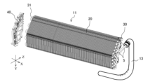
- FIG. 1 is a perspective view showing an air-conditioning heat exchanger according to Embodiment 1.
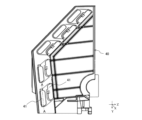
- FIG. 4 is a front view of the holder according to Embodiment 1.
- FIG. 4 is a partial perspective view of the cylindrical portion of the holder and the heat transfer tube according to Embodiment 1.
- FIG. 4 is a simplified front view showing a tubular portion and a hairpin portion of the holder according to Embodiment 1;
- 2 is a schematic diagram showing a hydrophilic portion according to Embodiment 1;
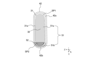
- FIG. FIG. 4 is a schematic vertical cross-sectional view taken along the line AA of FIG.
- FIG. 3; 4 is a schematic diagram showing a state in which condensed water remains between the outer peripheral surface of the hairpin portion and the inner peripheral surface of the cylindrical portion of the holder in Embodiment 1.
- FIG. FIG. 8 is a schematic diagram showing a water-repellent portion according to Embodiment 2;
- FIG. 8 is a schematic vertical cross-sectional view of a holder and a heat transfer tube according to Embodiment 2;
- FIG. 1 is a circuit diagram showing an air conditioner 1 according to Embodiment 1.
- the air conditioner 1 is a device that adjusts indoor air, and includes an outdoor unit 2 and an indoor unit 3 .
- the outdoor unit 2 is provided with, for example, a compressor 6 , a flow path switching device 7 , an outdoor heat exchanger 8 , an outdoor fan 9 , and an expansion section 10 .
- the indoor unit 3 is provided with, for example, an air-conditioning heat exchanger 11 and a fan 12 .
- a refrigerant circuit 4 is configured by connecting the compressor 6 , the flow path switching device 7 , the outdoor heat exchanger 8 , the expansion section 10 , and the air-conditioning heat exchanger 11 through refrigerant pipes 5 .
- the compressor 6 sucks in a low-temperature, low-pressure refrigerant, compresses the sucked-in refrigerant, converts it into a high-temperature, high-pressure refrigerant, and discharges it.
- the flow switching device 7 switches the direction in which the refrigerant flows in the refrigerant circuit 4, and is, for example, a four-way valve.
- the outdoor heat exchanger 8 exchanges heat, for example, between outdoor air and refrigerant.
- the outdoor heat exchanger 8 acts as a condenser during cooling operation and dehumidifying operation, and acts as an evaporator during heating operation.
- the outdoor fan 9 is a device that sends outdoor air to the outdoor heat exchanger 8 .
- the expansion section 10 is a pressure reducing valve or an expansion valve that reduces the pressure of the refrigerant to expand it.
- the expansion section 10 is, for example, an electronic expansion valve whose opening is adjusted.
- the air-conditioning heat exchanger 11 exchanges heat, for example, between indoor air and refrigerant.
- the air-conditioning heat exchanger 11 acts as an evaporator during cooling and dehumidifying operations, and acts as a condenser during heating operation.
- the blower 12 is a device that sends indoor air to the heat exchanger 11 for air conditioning.
- the condensed liquid refrigerant flows into the expansion section 10, where it is expanded and decompressed to become a low-temperature, low-pressure gas-liquid two-phase refrigerant. Then, the gas-liquid two-phase refrigerant flows into the air-conditioning heat exchanger 11 acting as an evaporator, where it is heat-exchanged with the room air sent by the blower 12 to evaporate. to gasify. At this time, the room air is cooled, so that the room is cooled or dehumidified. The vaporized low-temperature, low-pressure gaseous refrigerant passes through the flow switching device 7 and is sucked into the compressor 6 .
- heating operation Next, the heating operation will be explained.
- the refrigerant sucked into the compressor 6 is compressed by the compressor 6 and discharged in a high-temperature and high-pressure gas state.
- the high-temperature and high-pressure gaseous refrigerant discharged from the compressor 6 passes through the flow path switching device 7 and flows into the air-conditioning heat exchanger 11 acting as a condenser. , it is heat-exchanged with the indoor air sent by the blower 12 to condense and liquefy. At this time, indoor air is warmed, and heating is carried out in the room.
- the condensed liquid refrigerant flows into the expansion section 10, where it is expanded and decompressed to become a low-temperature, low-pressure gas-liquid two-phase refrigerant. Then, the gas-liquid two-phase refrigerant flows into the outdoor heat exchanger 8 that acts as an evaporator, and in the outdoor heat exchanger 8, heat is exchanged with the outdoor air sent by the outdoor fan 9 to evaporate and gasify. do.
- the vaporized low-temperature, low-pressure gaseous refrigerant passes through the flow switching device 7 and is sucked into the compressor 6 .
- FIG. 2 is a perspective view showing the air-conditioning heat exchanger 11 according to Embodiment 1.
- the first direction X is the width direction of the air-conditioning heat exchanger 11 .
- the second direction Y indicates the vertical direction of the air-conditioning heat exchanger 11 .
- the third direction Z is the front-rear direction of the air-conditioning heat exchanger 11 .
- the air-conditioning heat exchanger 11 includes multiple fins 20 , multiple heat transfer tubes 30 , and a holder 40 .
- fin 20 The plurality of fins 20 are arranged side by side at intervals in the first direction X, which is the width direction of the air-conditioning heat exchanger 11 .
- the indoor air drawn into the air-conditioning heat exchanger 11 passes through the plurality of fins 20 .
- the heat transfer tubes 30 are made of metal, for example, and provided so as to penetrate the plurality of fins 20 .
- the heat transfer tube 30 has a hairpin portion 31 that is folded back at the end in the first direction X. As shown in FIG. The hairpin portion 31 is bent at 180 degrees with a predetermined curvature.
- refrigerant flows inside the heat transfer tubes 30 .
- a part of the heat transfer tube 30 is exposed between the plurality of fins 20 arranged in the first direction X.
- the room air passing between the plurality of fins 20 hits the heat transfer tubes 30, and heat exchange is performed between the refrigerant flowing inside the heat transfer tubes 30 and the room air.
- the heat transfer tube 30 has a cylindrical shape.
- a refrigerant pipe 5 is connected to a portion of the heat transfer pipe 30 at one end in the first direction X. As shown in FIG.
- the refrigerant pipe 5 is covered with a pipe cover 13 .
- the refrigerant pipe 5 is protected by a pipe cover 13 and insulated from the outside air.
- the holder 40 is provided at one end in the first direction X in the unit in which the fins 20 and the heat transfer tubes 30 are combined, as shown in FIG.
- the end in the first direction X where the holder 40 is provided is the end opposite to the end where the refrigerant pipe 5 is connected to the heat transfer tube 30 .
- the holder 40 has a function of securing the strength of the air-conditioning heat exchanger 11 and protecting the hairpin portion 31 of the heat transfer tube 30 .
- the holder 40 is made of resin, for example.
- FIG. 3 is a front view of the holder 40 according to Embodiment 1.
- FIG. FIG. 4 is a partial perspective view of cylindrical portion 42 of holder 40 and heat transfer tube 30 according to the first embodiment.
- FIG. 4 shows the outlines of the holder 40, the fins 20, and the heat transfer tubes 30 in a simplified manner.
- FIG. 5 is a simplified front view showing cylindrical portion 42 and hairpin portion 31 of holder 40 according to the first embodiment.
- FIG. 5 shows a portion of the holder 40 extracted.
- FIG. 6 is a schematic diagram showing the hydrophilic portion 51 according to the first embodiment.
- FIG. 7 is a schematic vertical cross-sectional view taken along line AA of FIG.
- the holder 40 has an opening 41. Further, as shown in FIG. 4 , a cylindrical portion 42 of the holder 40 protrudes outward in the first direction X from the edge of the opening 41 of the holder 40 .
- the outside in the first direction X refers to the side opposite to the side where the fins 20 are located.
- the holder 40 has a cylindrical opening 43 facing the opening 41 .
- the heat transfer tube 30 has a first straight pipe portion 33 and a second straight pipe portion 34 arranged vertically.
- the first straight pipe portion 33 is positioned above the second straight pipe portion 34 .
- the hairpin portion 31 is provided between the first straight pipe portion 33 and the second straight pipe portion 34 and connects the first straight pipe portion 33 and the second straight pipe portion 34 .
- the top portion 32 of the hairpin portion 31 is positioned between the first straight pipe portion 33 and the second straight pipe portion 34 in the vertical direction.
- a portion of the heat transfer tube 30 that is accommodated in the cylindrical portion 42 of the holder 40 is called a hairpin portion 31 .
- the hairpin portion 31 includes a bent portion and a straight tube portion.
- the hairpin portion 31 of the heat transfer tube 30 is inserted into the opening 41 of the holder 40 and housed in the tubular portion 42 of the holder 40 .
- a portion of the outer peripheral surface 31a of the hairpin portion 31 and a portion of the inner peripheral surface 42a of the cylindrical portion 42 face each other.
- the cylindrical portion 42 has a bottom portion 42b.
- the tubular portion opening 43 is provided in the tubular portion 42 .
- a second hydrophilic portion 51b which will be described later, is provided on the inner peripheral surface 42a of the bottom portion 42b of the cylindrical portion 42.
- the hairpin portion 31 of the heat transfer tube 30 has a top portion 32 at the end portion in the first direction X.
- the apex 32 is the apex of the bent portion of the hairpin portion 31 .
- the hairpin portion 31 is housed in the tubular portion 42 of the holder 40 without protruding from the tubular portion 42 . Therefore, when the air-conditioning heat exchanger 11 is viewed in the front-rear direction, that is, in the third direction Z, the hairpin portion 31 is covered with the tubular portion 42 and is not visible. Since the hairpin portion 31 is housed in the cylindrical portion 42, it is less likely to be affected by the outside. In other words, the tubular portion 42 of the holder 40 protects the hairpin portion 31 . 4 to 7, one hairpin portion 31 is accommodated in one cylindrical portion 42. As shown in FIG. However, although not shown, a configuration may be adopted in which a plurality of hairpin portions 31 are housed in one tubular portion 42 .
- the tubular portion 42 of the holder 40 optimizes the airflow path of the air flowing through the heat exchanger 11 for air conditioning.
- the tubular portion 42 has the fins 20 instead of the air flowing into the air-conditioning heat exchanger 11 flowing in the third direction Z at the side portion of the air-conditioning heat exchanger 11 where the hairpin portion 31 is arranged.
- the air is made to flow in the first direction X toward the central portion of the air-conditioning heat exchanger 11 .
- the hydrophilic portion 51 of the outer peripheral surface 31a of the hairpin portion 31 and the inner peripheral surface 42a of the cylindrical portion 42 will be described with reference to FIGS. 6 and 7.
- FIG. 1 the outer peripheral surface 31a of the hairpin portion 31 has a first hydrophilic portion 51a formed by applying a hydrophilic film.
- the inner peripheral surface 42a of the tubular portion 42 has a second hydrophilic portion 51b formed by applying a hydrophilic film.
- hydrophilic portion 51 when there is no particular need to distinguish between the first hydrophilic portion 51a and the second hydrophilic portion 51b, they are simply referred to as "hydrophilic portion 51".
- hydrophilic portion 51 when used, both singular and plural portions are included.
- the hydrophilic film of the hydrophilic portion 51 is applied to the outer peripheral surface 31a of the hairpin portion 31 and the inner peripheral surface 42a of the cylindrical portion 42 by spray coating or brush coating, for example.
- not all of the outer peripheral surface 31a of the hairpin portion 31 has the first hydrophilic portion 51a, and all of the inner peripheral surface 42a of the cylindrical portion 42 has the second hydrophilic portion 51b. does not have.
- the first hydrophilic portion 51a of the outer peripheral surface 31a of the hairpin portion 31 is It is provided above the axis AX.
- the first hydrophilic portion 51a is not provided on the outer peripheral surface 31a of the hairpin portion 31 located below the axis AX in the vertical direction.
- the second hydrophilic portion 51b is provided below the axis AX on the inner peripheral surface 42a of the tubular portion 42. As shown in FIG. In other words, the second hydrophilic portion 51b is not provided on the inner peripheral surface 42a of the cylindrical portion 42 located above the axis AX in the vertical direction.
- the first hydrophilic portion 51a may not be provided in a portion of the outer peripheral surface 31a of the hairpin portion 31 located above the axis AX that does not face the inner peripheral surface 42a of the cylindrical portion 42.
- the first hydrophilic portion 51a may not be provided on the outer peripheral surface 31a of the bottom surface.
- the first hydrophilic portion 51a may not be provided on the outer peripheral surface 31a of the upper surface.
- the first hydrophilic portion 51a may not be provided on the outer peripheral surface 31a of the bent portion between the bottom surface of the upper straight pipe portion of the hairpin portion 31 and the upper surface of the lower straight pipe portion.
- the gap between the outer peripheral surface 31a of the hairpin portion 31 located above the axis AX and the inner peripheral surface 42a of the cylindrical portion 42 having the first hydrophilic portion 51a will be referred to as the gap SP1.
- a gap between the outer peripheral surface 31a of the hairpin portion 31 located below the axis AX and the inner peripheral surface 42a of the cylindrical portion 42, which does not have the first hydrophilic portion 51a is referred to as a gap SP2.
- gap SP1 and the gap SP2 are simply referred to as the "gap SP".
- the second hydrophilic portion 51b may be provided on the inner peripheral surface 42a of the bottom surface portion 42b of the tubular portion 42, as shown in FIGS. More preferably, the second hydrophilic portion 51b is provided in a portion of the inner peripheral surface 42a of the cylindrical portion 42 that faces the outer peripheral surface 31a of the hairpin portion 31 and faces the portion where the first hydrophilic portion 51a is not provided. Good. Further, when the second hydrophilic portion 51b is projected onto the outer peripheral surface 31a of the hairpin portion 31, the portion of the first hydrophilic portion 51a located below the axis AX does not overlap with the projected area of the second hydrophilic portion 51b. . That is, when the second hydrophilic portion 51b is projected onto the outer peripheral surface 31a of the hairpin portion 31, the first hydrophilic portion 51a is not provided in the projection area.
- the hydrophilic portion 51 prevents the condensed water 50 from remaining in a state of blocking the gap SP between the outer peripheral surface 31 a of the hairpin portion 31 and the inner peripheral surface 42 a of the cylindrical portion 42 .
- FIG. 8 is a schematic diagram showing a state in which condensed water 50 remains between the outer peripheral surface 31a of the hairpin portion 31 and the inner peripheral surface 42a of the tubular portion 42 of the holder 40 in the first embodiment.
- the heat transfer tubes 30 are cooled by the refrigerant flowing inside the heat transfer tubes 30 .
- the humidity around the heat transfer tube 30 is high, dew condensation may occur on the surface of the heat transfer tube 30 .
- the condensed water 50 straddled the gap SP between the outer peripheral surface 31a of the hairpin portion 31 and the inner peripheral surface 42a of the cylindrical portion 42. adhere to the state. That is, the condensed water 50 closes the gap SP. In such a state, the condensed water 50 becomes difficult to move and stays in the gap SP for a long time.
- the condensed water 50 since the hydrophilic portion 51 is provided in a part of the portion where the gap SP contacts, the condensed water 50 preferentially moves to the hydrophilic portion 51 . Therefore, it is difficult for the condensed water 50 to stay in one place in the gap SP1 between the outer peripheral surface 31a of the hairpin portion 31 having the first hydrophilic portion 51a and the inner peripheral surface 42a of the tubular portion 42 . Also, the condensed water 50 flows vertically along the outer peripheral surface 31a of the hairpin portion 31 due to gravity and gathers. Since the heat transfer tube 30 has a cylindrical shape, the condensed water 50 tends to collect on the outer peripheral surface 31 a of the bottom surface of the straight tube portion of the hairpin portion 31 .
- the condensed water 50 is less likely to remain in the gap SP1 between the outer peripheral surface 31a of the hairpin portion 31 located above the axis AX and the inner peripheral surface 42a of the tubular portion 42 . Further, since the contact angle of the condensed water 50 is small in the first hydrophilic portion 51a, a large amount of the condensed water 50 needs to gather in order for the condensed water 50 to block the gap SP. However, the gap SP1 between the outer peripheral surface 31a of the hairpin portion 31 located above the axis AX and the inner peripheral surface 42a of the tubular portion 42 is difficult for the condensed water 50 to stay in, so the gap SP1 is blocked by the condensed water 50. is suppressed.
- the condensed water 50 dropped from the hairpin portion 31 is received by the inner peripheral surface 42a of the bottom portion 42b of the cylindrical portion 42. Since the inner peripheral surface 42a of the bottom surface portion 42b of the cylindrical portion 42 is provided with the second hydrophilic portion 51b, the contact angle of the condensed water 50 is small. A large amount of the condensed water 50 needs to gather in order for the condensed water 50 to close the gap SP2, but it is difficult for a large amount of the condensed water 50 to stay in one place in the second hydrophilic portion 51b.
- the first hydrophilic portion 51a of the hairpin portion 31 is not provided on the opposite side of the second hydrophilic portion 51b.
- the condensed water 50 adheres to the gap SP2 between the inner peripheral surface 42a of the bottom surface portion 42b of the cylindrical portion 42 and the outer peripheral surface 31a of the hairpin portion 31, the condensed water 50 It moves preferentially to the second hydrophilic portion 51b. Therefore, between the inner peripheral surface 42a of the bottom surface portion 42b of the cylindrical portion 42 and the outer peripheral surface 31a of the hairpin portion 31, the condensed water 50 is less likely to stay in a state of closing the gap SP2.
- the air-conditioning heat exchanger 11 includes the plurality of fins 20 arranged at intervals in the first direction X, and the plurality of fins 20 penetrating the , a heat transfer tube 30 having a hairpin portion 31 folded back at the end in the first direction X, and a holder 40 having a cylindrical portion 42 in which the hairpin portion 31 is accommodated.
- the heat transfer tube 30 has a first straight pipe portion 33 and a second straight pipe portion 34 arranged vertically. is provided between the first straight pipe portion 33 and the second straight pipe portion 34 and connects the first straight pipe portion 33 and the second straight pipe portion 34 .
- the outer peripheral surface 31 a of the hairpin portion 31 has a first hydrophilic portion 51 a formed with a hydrophilic coating in a portion positioned above the axis AX of the second straight pipe portion 34 in the vertical direction.
- the inner peripheral surface 42a of the bottom surface portion 42b of has a second hydrophilic portion 51b formed with a hydrophilic film.
- the outer peripheral surface 31a of the hairpin portion 31 of the heat transfer tube 30 located above the axis AX in the vertical direction has the first hydrophilic portion 51a.
- the inner peripheral surface 42a of the cylindrical portion 42 located above the axis AX does not have the second hydrophilic portion 51b. Therefore, in the gap SP1 between the outer peripheral surface 31a of the hairpin portion 31 and the inner peripheral surface 42a of the tubular portion 42 located above the axis AX, the condensed water 50 preferentially moves to the first hydrophilic portion 51a. . Therefore, above the axis AX, it is difficult for the condensed water 50 to remain in a state in which the gap SP1 is closed.
- the condensed water 50 flows vertically on the outer peripheral surface 31a of the hairpin portion 31 and gathers, so that the condensed water 50 tends to drop from the outer peripheral surface 31a of the hairpin portion 31 due to gravity. Also, the condensed water 50 dropped from the hairpin portion 31 is received by the inner peripheral surface 42a of the bottom surface portion 42b of the cylindrical portion 42, and preferentially moves to the second hydrophilic portion 51b. Therefore, the gap SP2 between the inner peripheral surface 42a of the bottom surface portion 42b of the cylindrical portion 42 and the outer peripheral surface 31a of the hairpin portion 31 facing each other is not easily blocked by the condensed water 50.
- the first hydrophilic portion 51a is not provided in the area where the second hydrophilic portion 51b is projected onto the outer peripheral surface 31a of the hairpin portion 31 .
- the second hydrophilic portion 51b is provided on a portion of the outer peripheral surface 31a of the hairpin portion 31 that faces the portion that does not have the first hydrophilic portion 51a. Condensed water 50 dropped from the outer peripheral surface 31a of the hairpin portion 31 located above the axis AX may adhere to the outer peripheral surface 31a of the hairpin portion 31 located below the axis AX.
- the outer peripheral surface 31 a of the hairpin portion 31 located below the axis AX does not have the hydrophilic portion 51 . Therefore, the condensed water 50 that has fallen and the condensed water 50 that has originally adhered are likely to gather, and the condensed water 50 is likely to adhere across the gap SP2.
- the inner peripheral surface 42a of the tubular portion 42 has the second hydrophilic portion 51b, the condensed water 50 preferentially moves to the second hydrophilic portion 51b. Therefore, it is possible to prevent the condensed water 50 from blocking the gap SP2 between the outer peripheral surface 31a of the hairpin portion 31 and the inner peripheral surface 42a of the cylindrical portion 42 below the axis AX. Therefore, it is possible to prevent the dew condensation water 50 from adhering to the outer peripheral surface 31a of the hairpin portion 31 located below the axis AX for a long period of time.
- Embodiment 2 The difference between the air-conditioning heat exchanger 11 according to Embodiment 2 and the air-conditioning heat exchanger 11 according to Embodiment 1 is that the outer peripheral surface 31 a of the hairpin portion 31 has the water-repellent portion 52 . be.
- the water-repellent portion 52 according to the present embodiment will be described below, focusing on differences from the first embodiment. Except for the water-repellent portion 52, the configuration of the air-conditioning heat exchanger 11 of the present embodiment is the same as the configuration of the first embodiment, so descriptions other than the water-repellent portion 52 will be omitted. Also, the same reference numerals are given to the same components as those in the first embodiment, and the description thereof will be omitted as appropriate.
- FIG. 9 is a schematic diagram showing a water-repellent portion 52 according to the second embodiment.
- FIG. 10 is a vertical cross-sectional schematic diagram of the holder 40 and the heat transfer tube 30 according to the second embodiment.
- FIG. 10 shows a longitudinal section taken along line AA of FIG.
- the water-repellent portion 52 is painted out for visibility.
- the outer peripheral surface 31a of the hairpin portion 31 has a water-repellent portion 52 on which a water-repellent film is formed.
- the water-repellent portion 52 is provided at a portion of the outer peripheral surface 31a of the hairpin portion 31 located below the axis AX. More specifically, the water-repellent portion 52 is provided in a portion of the outer peripheral surface 31a of the hairpin portion 31 located below the axis AX where the first hydrophilic portion 51a is not provided.
- the contact angle of the condensed water 50 increases, and the condensed water 50 adheres to the water-repellent portion 52 in a substantially spherical shape. Therefore, the condensed water 50 rolls on the water-repellent portion 52 and easily gathers on the outer peripheral surface 31 a of the bottom surface of the straight pipe portion located below the hairpin portion 31 . For this reason, the condensed water 50 adheres to the gap SP2 between the outer peripheral surface 31a of the bottom surface of the straight pipe portion of the hairpin portion 31 and the inner peripheral surface 42a of the bottom surface portion 42b of the tubular portion 42 while spanning the gap.
- Cheap
- the condensed water 50 preferentially moves to the second hydrophilic portion 51b. Therefore, in the gap SP2 located below the axis AX, the condensed water 50 blocks the space between the outer peripheral surface 31a of the bottom surface of the straight pipe portion of the hairpin portion 31 and the inner peripheral surface 42a of the bottom surface portion 42b of the cylindrical portion 42. You can restrain yourself from staying in a state of Therefore, the occurrence of corrosion in the hairpin portion 31 can be suppressed, and as a result, the highly reliable air-conditioning heat exchanger 11 can be provided.
- the water-repellent portion 52 is provided at a position facing the second hydrophilic portion 51b. Even when the amount of the condensed water 50 adhering to the water repellent portion 52 is small, the condensed water 50 adheres in a substantially spherical shape. easy to come into contact with. Since the inner peripheral surface 42a of the cylindrical portion 42 facing the water-repellent portion 52 has the second hydrophilic portion 51b, the condensed water 50 preferentially moves to the second hydrophilic portion 51b.
- the condensed water 50 can preferentially move to the second hydrophilic portion 51b of the inner peripheral surface 42a of the tubular portion 42 . Therefore, the dew condensation water 50 is prevented from adhering to the hairpin portion 31 for a long time. Therefore, the occurrence of corrosion in the hairpin portion 31 can be suppressed, and as a result, the highly reliable air-conditioning heat exchanger 11 can be provided.
Landscapes
- Engineering & Computer Science (AREA)
- Physics & Mathematics (AREA)
- Thermal Sciences (AREA)
- Mechanical Engineering (AREA)
- General Engineering & Computer Science (AREA)
- Heat-Exchange Devices With Radiators And Conduit Assemblies (AREA)
Abstract
空気調和用熱交換器は、第1方向に間隔を空けて配置された複数のフィンと、複数のフィンを貫通して設けられた、第1方向の端部で折り返すヘアピン部を有する伝熱管と、ヘアピン部が収納される筒部を有するホルダとを備え、伝熱管は、鉛直方向に並ぶ第1直管部と第2直管部とを有し、第1直管部は、第2直管部の上部に位置し、ヘアピン部は、第1直管部と第2直管部との間に設けられ、第1直管部と第2直管部とを接続し、ヘアピン部の外周面は、鉛直方向において、第2直管部の軸線よりも上方に位置する部分に、親水性被膜が形成された第1親水部を有し、筒部の底面部の内周面は、親水性被膜が形成された第2親水部を有する。
Description
本開示は、伝熱管のヘアピン部を収納するホルダを備える空気調和用熱交換器に関する。
空気調和用熱交換器として、複数のフィンと、一端がヘアピン部で折り返されて複数のフィンを貫通する伝熱管と、伝熱管のヘアピン部を収納するホルダとを備える空気調和用熱交換器が知られている。例えば、特許文献1には、強度確保と、風路最適化と、ヘアピン部での腐食防止といった作用を有するホルダを備えた空気調和用熱交換器が記載されている。
ここで、特許文献1に記載されたような空気調和用熱交換器では、冷房運転時に熱交換器の表面に発生した結露水が、ヘアピン部とホルダの内周面との隙間に表面張力によって留まり続けるために、ヘアピン部での腐食の発生が懸念される。そのため、特許文献1では、結露水が流れ落ちるように、ヘアピン部とホルダの内周面との間の隙間を十分に開けて結露水の留まりを防止し、腐食の発生を回避することが提案されている。
しかしながら、ヘアピン部に付着する結露水は、重力によりヘアピン部の鉛直方向に集合しやすい。よって、ヘアピン部とホルダの内周面との間に十分な隙間があっても、結露水が集合して、隙間を塞いだ状態で表面張力によって留まり続けることがある。また、ヘアピン部から落下した結露水は、ホルダの底面で受け止められる。このため、ヘアピン部から結露水が落下した場合でも、伝熱管とホルダの底面との間の隙間を結露水が塞いだ状態で留まり続けることがある。したがって、伝熱管とホルダの内周面との間の隙間に結露水が長時間留まることによって、ヘアピン部で腐食が発生するおそれがある。
本開示は、上記のような課題を解決するためになされたもので、伝熱管のヘアピン部での腐食の発生を抑制する空気調和用熱交換器を提供するものである。
本開示に係る空気調和用熱交換器は、第1方向に間隔を空けて配置された複数のフィンと、複数のフィンを貫通して設けられた、第1方向の端部で折り返すヘアピン部を有する伝熱管と、ヘアピン部が収納される筒部を有するホルダとを備え、伝熱管は、鉛直方向に並ぶ第1直管部と第2直管部とを有し、第1直管部は、第2直管部の上部に位置し、ヘアピン部は、第1直管部と第2直管部との間に設けられ、第1直管部と第2直管部とを接続し、ヘアピン部の外周面は、鉛直方向において、第2直管部の軸線よりも上方に位置する部分に、親水性被膜が形成された第1親水部を有し、筒部の底面部の内周面は、親水性被膜が形成された第2親水部を有する。
本開示によれば、伝熱管のヘアピン部は、第2直管部の軸線よりも上方に位置する外周面に、親水性被膜が形成された第1親水部を有する。また、ヘアピン部が収納されるホルダの筒部は、底面部の内周面に、親水性被膜が形成された第2親水部を有する。このため、第2直管部の軸線よりも上方では、第1親水部によって結露水が移動しやすくなり、ヘアピン部の外周面とホルダの筒部の内周面との間の隙間を塞ぐように結露水が留まることが抑制される。また、ホルダの底面部では、第2親水部によって結露水が移動しやすくなり、ホルダの内周面とヘアピン部の外周面との間の隙間を塞ぐように結露水が留まることが抑制される。したがって、結露水が伝熱管のヘアピン部に長時間付着することを抑制できるため、ヘアピン部での腐食の発生を抑制できる。
以下、本開示に係る空気調和用熱交換器の実施の形態について、添付の図面を参照して説明する。なお、図面の形態は一例であり、本開示を限定するものではない。また、各図において同一の符号を付したものは、同一のまたはこれに相当するものであり、これは明細書の全文において共通している。以下の説明において、重複するものについては、適宜簡略化または省略する。なお、本開示は、以下に説明する実施の形態によって限定されるものではなく、以下の実施の形態によって開示される構成のあらゆる組み合わせを含み得るものである。また、添付の図面における各構成部材の位置、形状、及び大きさは、実際のものとは異なる場合がある。さらに、添付の図面の断面図においては、視認性に鑑みて適宜ハッチングを省略している。
また、以下の説明において、理解を容易にするために方向を表す用語を適宜用いるが、これは説明のためのものであって、これらの用語は本開示を限定するものではない。方向を表す用語としては、例えば、「上」、「下」、「右」、「左」、「前」、又は「後」が挙げられる。
実施の形態1.
図1は、実施の形態1に係る空気調和装置1を示す回路図である。空気調和装置1は、室内の空気を調整する装置であり、室外機2と、室内機3とを備えている。室外機2には、例えば圧縮機6、流路切替装置7、室外熱交換器8、室外送風機9、及び膨張部10が設けられている。室内機3には、例えば空気調和用熱交換器11及び送風機12が設けられている。
図1は、実施の形態1に係る空気調和装置1を示す回路図である。空気調和装置1は、室内の空気を調整する装置であり、室外機2と、室内機3とを備えている。室外機2には、例えば圧縮機6、流路切替装置7、室外熱交換器8、室外送風機9、及び膨張部10が設けられている。室内機3には、例えば空気調和用熱交換器11及び送風機12が設けられている。
圧縮機6、流路切替装置7、室外熱交換器8、膨張部10、及び空気調和用熱交換器11が冷媒配管5により接続されて冷媒回路4が構成されている。圧縮機6は、低温且つ低圧の状態の冷媒を吸入し、吸入した冷媒を圧縮して高温且つ高圧の状態の冷媒にして吐出するものである。流路切替装置7は、冷媒回路4において冷媒が流れる方向を切り替えるものであり、例えば四方弁である。室外熱交換器8は、例えば室外空気と冷媒との間で熱交換するものである。室外熱交換器8は、冷房運転時及び除湿運転時には凝縮器として作用し、暖房運転時には蒸発器として作用する。室外送風機9は、室外熱交換器8に室外空気を送る機器である。
膨張部10は、冷媒を減圧して膨張する減圧弁又は膨張弁である。膨張部10は、例えば開度が調整される電子式膨張弁である。空気調和用熱交換器11は、例えば室内空気と冷媒との間で熱交換するものである。空気調和用熱交換器11は、冷房運転時及び除湿運転時には蒸発器として作用し、暖房運転時には凝縮器として作用する。送風機12は、空気調和用熱交換器11に室内空気を送る機器である。
(冷房運転及び除湿運転)
次に、空気調和装置1の動作について説明する。先ず、冷房運転及び除湿運転について説明する。冷房運転及び除湿運転において、圧縮機6に吸入された冷媒は、圧縮機6によって圧縮されて高温且つ高圧のガス状態で吐出される。圧縮機6から吐出された高温且つ高圧のガス状態の冷媒は、流路切替装置7を通過して、凝縮器として作用する室外熱交換器8に流入し、室外熱交換器8において、室外送風機9によって送られる室外空気と熱交換されて凝縮して液化する。凝縮された液状態の冷媒は、膨張部10に流入し、膨張部10において膨張及び減圧されて低温且つ低圧の気液二相状態の冷媒となる。そして、気液二相状態の冷媒は、蒸発器として作用する空気調和用熱交換器11に流入し、空気調和用熱交換器11において、送風機12によって送られる室内空気と熱交換されて蒸発してガス化する。このとき、室内空気が冷やされることで、室内において冷房又は除湿が実施される。蒸発した低温且つ低圧のガス状態の冷媒は、流路切替装置7を通過して、圧縮機6に吸入される。
次に、空気調和装置1の動作について説明する。先ず、冷房運転及び除湿運転について説明する。冷房運転及び除湿運転において、圧縮機6に吸入された冷媒は、圧縮機6によって圧縮されて高温且つ高圧のガス状態で吐出される。圧縮機6から吐出された高温且つ高圧のガス状態の冷媒は、流路切替装置7を通過して、凝縮器として作用する室外熱交換器8に流入し、室外熱交換器8において、室外送風機9によって送られる室外空気と熱交換されて凝縮して液化する。凝縮された液状態の冷媒は、膨張部10に流入し、膨張部10において膨張及び減圧されて低温且つ低圧の気液二相状態の冷媒となる。そして、気液二相状態の冷媒は、蒸発器として作用する空気調和用熱交換器11に流入し、空気調和用熱交換器11において、送風機12によって送られる室内空気と熱交換されて蒸発してガス化する。このとき、室内空気が冷やされることで、室内において冷房又は除湿が実施される。蒸発した低温且つ低圧のガス状態の冷媒は、流路切替装置7を通過して、圧縮機6に吸入される。
(暖房運転)
次に、暖房運転について説明する。暖房運転において、圧縮機6に吸入された冷媒は、圧縮機6によって圧縮されて高温且つ高圧のガス状態で吐出される。圧縮機6から吐出された高温且つ高圧のガス状態の冷媒は、流路切替装置7を通過して、凝縮器として作用する空気調和用熱交換器11に流入し、空気調和用熱交換器11において、送風機12によって送られる室内空気と熱交換されて凝縮して液化する。このとき、室内空気が暖められ、室内において暖房が実施される。凝縮された液状態の冷媒は、膨張部10に流入し、膨張部10において膨張及び減圧されて低温且つ低圧の気液二相状態の冷媒となる。そして、気液二相状態の冷媒は、蒸発器として作用する室外熱交換器8に流入し、室外熱交換器8において、室外送風機9によって送られる室外空気と熱交換されて蒸発してガス化する。蒸発した低温且つ低圧のガス状態の冷媒は、流路切替装置7を通過して、圧縮機6に吸入される。
次に、暖房運転について説明する。暖房運転において、圧縮機6に吸入された冷媒は、圧縮機6によって圧縮されて高温且つ高圧のガス状態で吐出される。圧縮機6から吐出された高温且つ高圧のガス状態の冷媒は、流路切替装置7を通過して、凝縮器として作用する空気調和用熱交換器11に流入し、空気調和用熱交換器11において、送風機12によって送られる室内空気と熱交換されて凝縮して液化する。このとき、室内空気が暖められ、室内において暖房が実施される。凝縮された液状態の冷媒は、膨張部10に流入し、膨張部10において膨張及び減圧されて低温且つ低圧の気液二相状態の冷媒となる。そして、気液二相状態の冷媒は、蒸発器として作用する室外熱交換器8に流入し、室外熱交換器8において、室外送風機9によって送られる室外空気と熱交換されて蒸発してガス化する。蒸発した低温且つ低圧のガス状態の冷媒は、流路切替装置7を通過して、圧縮機6に吸入される。
(空気調和用熱交換器11)
図2は、実施の形態1に係る空気調和用熱交換器11を示す斜視図である。本開示では、図2に示すように、第1方向Xは、空気調和用熱交換器11の幅方向を示すこととする。第2方向Yは、空気調和用熱交換器11の上下方向を示すこととする。第3方向Zは、空気調和用熱交換器11の前後方向を示すこととする。空気調和用熱交換器11は、複数のフィン20と、複数の伝熱管30と、ホルダ40とを備えている。
図2は、実施の形態1に係る空気調和用熱交換器11を示す斜視図である。本開示では、図2に示すように、第1方向Xは、空気調和用熱交換器11の幅方向を示すこととする。第2方向Yは、空気調和用熱交換器11の上下方向を示すこととする。第3方向Zは、空気調和用熱交換器11の前後方向を示すこととする。空気調和用熱交換器11は、複数のフィン20と、複数の伝熱管30と、ホルダ40とを備えている。
(フィン20)
複数のフィン20は、空気調和用熱交換器11の幅方向である第1方向Xに間隔を空けて並べて配置されている。空気調和用熱交換器11の内部に吸い込まれた室内空気は、複数のフィン20の間を通過する。
複数のフィン20は、空気調和用熱交換器11の幅方向である第1方向Xに間隔を空けて並べて配置されている。空気調和用熱交換器11の内部に吸い込まれた室内空気は、複数のフィン20の間を通過する。
(伝熱管30)
伝熱管30は、例えば金属製であり、複数のフィン20を貫通して設けられる。伝熱管30は、第1方向Xの端部で折り返すヘアピン部31を有する。ヘアピン部31は、所定の曲率で180度に折り曲げられている。空気調和装置1が運転中の場合、冷媒が伝熱管30の内部を流れる。第1方向Xに並ぶ複数のフィン20の間から伝熱管30の一部が露出している。これにより、複数のフィン20の間を通過する室内空気が伝熱管30に当たり、伝熱管30の内部を流れる冷媒と、室内空気との間で熱交換が行われる。伝熱管30は円筒形状を有する。第1方向Xの一方の端部において、伝熱管30の一部には、冷媒配管5が接続されている。冷媒配管5は、パイプカバー13で覆われている。冷媒配管5は、パイプカバー13により保護されるとともに外気と断熱されている。
伝熱管30は、例えば金属製であり、複数のフィン20を貫通して設けられる。伝熱管30は、第1方向Xの端部で折り返すヘアピン部31を有する。ヘアピン部31は、所定の曲率で180度に折り曲げられている。空気調和装置1が運転中の場合、冷媒が伝熱管30の内部を流れる。第1方向Xに並ぶ複数のフィン20の間から伝熱管30の一部が露出している。これにより、複数のフィン20の間を通過する室内空気が伝熱管30に当たり、伝熱管30の内部を流れる冷媒と、室内空気との間で熱交換が行われる。伝熱管30は円筒形状を有する。第1方向Xの一方の端部において、伝熱管30の一部には、冷媒配管5が接続されている。冷媒配管5は、パイプカバー13で覆われている。冷媒配管5は、パイプカバー13により保護されるとともに外気と断熱されている。
(ホルダ40及びヘアピン部31)
ホルダ40は、図2に示すように、フィン20と伝熱管30とが組み合わされたユニットにおいて、第1方向Xの一方の端部に設けられる。ホルダ40が設けられる第1方向Xの端部は、伝熱管30に冷媒配管5が接続される端部とは反対側の端部である。ホルダ40は、空気調和用熱交換器11の強度を確保し、伝熱管30のヘアピン部31を保護する機能を有する。ホルダ40は、例えば樹脂製である。
ホルダ40は、図2に示すように、フィン20と伝熱管30とが組み合わされたユニットにおいて、第1方向Xの一方の端部に設けられる。ホルダ40が設けられる第1方向Xの端部は、伝熱管30に冷媒配管5が接続される端部とは反対側の端部である。ホルダ40は、空気調和用熱交換器11の強度を確保し、伝熱管30のヘアピン部31を保護する機能を有する。ホルダ40は、例えば樹脂製である。
ホルダ40及び伝熱管30のヘアピン部31について、図3~図7を参照しながら説明する。図3は、実施の形態1に係るホルダ40の正面図である。図4は、実施の形態1に係るホルダ40の筒部42と伝熱管30の部分斜視図である。図4ではホルダ40、フィン20、及び伝熱管30の外形を簡略化して示している。図5は、実施の形態1に係るホルダ40の筒部42とヘアピン部31を示す簡略正面図である。図5はホルダ40の一部を抜き出して示している。図6は、実施の形態1に係る親水部51を示す概略図である。図7は、図3のA-A線での縦断面模式図である。
図3に示すように、ホルダ40は、開口部41を有する。また、図4に示すように、ホルダ40の開口部41の縁部から、ホルダ40の筒部42が第1方向Xの外側に向かって突出している。ここで、第1方向Xの外側とは、フィン20が位置する側とは反対側をさす。ホルダ40は、開口部41に対面する筒部開口43を有する。
図4及び図7に示すように、伝熱管30は、鉛直方向に並ぶ第1直管部33及び第2直管部34を有する。第1直管部33は、第2直管部34より上部に位置する。ヘアピン部31は、第1直管部33と第2直管部34との間に設けられ、第1直管部33と第2直管部34とを接続する。ヘアピン部31の頂部32は、鉛直方向において、第1直管部33と第2直管部34との中間に位置する。伝熱管30において、ホルダ40の筒部42に収納される部分をヘアピン部31という。ヘアピン部31は、曲げ部及ぶ直管部分を含む。
図4に示すように、伝熱管30のヘアピン部31は、ホルダ40の開口部41に挿入されて、ホルダ40の筒部42に収納される。ヘアピン部31の外周面31aの一部と、筒部42の内周面42aの一部は対面する。筒部42は、底面部42bを有する。筒部開口43は、筒部42に設けられる。筒部42の底面部42bの内周面42aには、後述する第2親水部51bが設けられる。図4及び図5に示すように、筒部開口43から、鉛直方向に延びるヘアピン部31が目視できる。
伝熱管30のヘアピン部31は、第1方向Xの端部に頂部32を有する。頂部32は、ヘアピン部31の曲げ部の頂点である。ヘアピン部31は、図4及び図7に示すように、ホルダ40の筒部42からはみ出すことなく、筒部42に収納される。よって、空気調和用熱交換器11を前後方向、すなわち第3方向Zに見たとき、ヘアピン部31は筒部42に覆われており目視されない。ヘアピン部31は、筒部42に収納されることにより、外部からの影響を受けにくい。言い換えると、ホルダ40の筒部42がヘアピン部31を保護している。なお、図4~図7では、1つの筒部42に1つのヘアピン部31が収納されている。しかし、図示しないが、1つの筒部42に複数のヘアピン部31が収納される構成としてもよい。
ホルダ40の筒部42は、空気調和用熱交換器11に流れる空気の風路を最適化する。筒部42は、空気調和用熱交換器11に流れ込む空気が、ヘアピン部31が配置されている空気調和用熱交換器11の側部で第3方向Zに流れるのではなく、フィン20が配置されている空気調和用熱交換器11の中央部に向かって、第1方向Xに流れるようにする。図5に示すように、筒部42に挿入されたヘアピン部31の外周面31aと、筒部42の内周面42aとの間には、隙間SPがある。よって、空気は、この隙間SPを通って空気調和用熱交換器11の中央部に向かって流れることができる。
(親水部51)
次に図6及び図7を参照しながら、ヘアピン部31の外周面31a及び筒部42の内周面42aが有する親水部51について説明する。図6及び図7に示すように、ヘアピン部31の外周面31aは、親水性被膜が塗布されることで形成された第1親水部51aを有する。また、筒部42の内周面42aは、親水性被膜が塗布されることで形成された第2親水部51bを有する。以下の説明において、第1親水部51aと第2親水部51bとを特に区別する必要がない場合には、単に「親水部51」と適宜称する。また、「親水部51」と称した場合には、単数又は複数の両方を含むものとする。親水部51の親水性被膜は、例えば、スプレー塗装や刷毛塗塗装により、ヘアピン部31の外周面31a及び筒部42の内周面42aに塗布される。
次に図6及び図7を参照しながら、ヘアピン部31の外周面31a及び筒部42の内周面42aが有する親水部51について説明する。図6及び図7に示すように、ヘアピン部31の外周面31aは、親水性被膜が塗布されることで形成された第1親水部51aを有する。また、筒部42の内周面42aは、親水性被膜が塗布されることで形成された第2親水部51bを有する。以下の説明において、第1親水部51aと第2親水部51bとを特に区別する必要がない場合には、単に「親水部51」と適宜称する。また、「親水部51」と称した場合には、単数又は複数の両方を含むものとする。親水部51の親水性被膜は、例えば、スプレー塗装や刷毛塗塗装により、ヘアピン部31の外周面31a及び筒部42の内周面42aに塗布される。
図6及び図7に示すように、ヘアピン部31の外周面31aの全てが第1親水部51aを有するわけではなく、また、筒部42の内周面42aの全てが第2親水部51bを有するわけではない。図7に示すように、伝熱管30の第2直管部34の軸線AXをヘアピン部31まで延ばした場合、鉛直方向において、第1親水部51aは、ヘアピン部31の外周面31aのうち、軸線AXよりも上方に設けられる。別の言い方をすると、鉛直方向において、第1親水部51aは、軸線AXより下方に位置するヘアピン部31の外周面31aには設けられない。また、図6に示すように、第2親水部51bは、筒部42の内周面42aのうち、軸線AXよりも下方に設けられる。別の言い方をすると、鉛直方向において、第2親水部51bは、軸線AXより上方に位置する筒部42の内周面42aには設けられない。
さらに、軸線AXより上方に位置するヘアピン部31の外周面31aにおいて、筒部42の内周面42aと対面しない部分には第1親水部51aが設けられなくてもよい。例えば、図7に示すように、伝熱管30の第1直管部33につながるヘアピン部31の直管部分については、底面の外周面31aには第1親水部51aが設けられなくてもよい。また、伝熱管30の第2直管部34につながるヘアピン部31の直管部分については、上面の外周面31aには第1親水部51aが設けられなくてもよい。さらに、ヘアピン部31の上部の直管部分の底面と、下部の直管部分の上面との間の曲げ部の外周面31aに第1親水部51aが設けられなくてもよい。
以下、説明を容易にするため、第1親水部51aを有する、軸線AXより上方に位置するヘアピン部31の外周面31aと、筒部42の内周面42aとの間の隙間を隙間SP1と称する。また、第1親水部51aを有しない、軸線AXより下方に位置するヘアピン部31の外周面31aと、筒部42の内周面42aとの間の隙間を隙間SP2と称する。また、隙間SP1と隙間SP2とを特に区別する必要がない場合には、単に「隙間SP」と適宜称する。
第2親水部51bは、図6及び図7に示すように、筒部42の底面部42bの内周面42aに設けられていればよい。より好ましくは、第2親水部51bは、ヘアピン部31の外周面31aに対面する筒部42の内周面42aのうち、第1親水部51aが設けられていない部分に対面する部分に設けられるとよい。また、ヘアピン部31の外周面31aに第2親水部51bを投影した場合、軸線AXより下方に位置する第1親水部51aの部分と、第2親水部51bが投影された領域とは重複しない。すなわち、ヘアピン部31の外周面31aに第2親水部51bを投影すると、その投影領域には、第1親水部51aが設けられていない。
親水部51により、結露水50が、ヘアピン部31の外周面31aと筒部42の内周面42aとの間の隙間SPを塞いだ状態で留まることが抑制される。まず、ヘアピン部31の外周面31aと筒部42の内周面42aとの間の隙間SPに結露水50が留まる状態について、図8を参照しながら説明する。図8は、実施の形態1においてヘアピン部31の外周面31aとホルダ40の筒部42の内周面42aとの間に結露水50が留まった状態を示す概略図である。
空気調和装置1が冷房運転又は除湿運転を実施して空気調和用熱交換器11が蒸発器として作用する際、伝熱管30の内部に流れる冷媒によって伝熱管30が冷却される。このとき、伝熱管30の周囲の湿度が高いと、伝熱管30の表面に結露が発生する場合がある。冷房運転又は除湿運転が続けられる間に、結露水50の量が次第に多くなると、ヘアピン部31の外周面31aと筒部42の内周面42aとの間の隙間SPに結露水50が跨った状態で付着する。つまり、結露水50が隙間SPを塞いだ状態となる。このような状態では、結露水50は、移動しにくくなり、隙間SPに長時間留まることになる。
本実施の形態においては、隙間SPが接する部分の一部に親水部51が設けられているため、結露水50は、親水部51に優先して移動する。このため、第1親水部51aを有するヘアピン部31の外周面31aと、筒部42の内周面42aとの間の隙間SP1には、結露水50が一箇所に留まりにくい。また、重力により結露水50はヘアピン部31の外周面31aを鉛直方向に流れて集合する。伝熱管30は円筒形状を有するため、ヘアピン部31の直管部分の底面の外周面31aに結露水50は集合しやすい。よって、軸線AXより上方に位置するヘアピン部31の外周面31aと、筒部42の内周面42aとの間の隙間SP1には、結露水50が留まりにくい。また、第1親水部51aでは、結露水50の接触角が小さいため、結露水50が隙間SPを塞ぐためには結露水50が多量に集合する必要がある。しかし、軸線AXより上方に位置するヘアピン部31の外周面31aと、筒部42の内周面42aとの間の隙間SP1には結露水50が留まりにくいため、結露水50で塞がれることが抑制される。
また、ヘアピン部31から落下した結露水50は、筒部42の底面部42bの内周面42aに受け止められる。筒部42の底面部42bの内周面42aには第2親水部51bが設けられているため、結露水50の接触角が小さい。結露水50が隙間SP2を塞ぐためには結露水50が多量に集合する必要があるが、第2親水部51bでは結露水50が一箇所に多量に留まりにくい。また、第2親水部51bの対面には、ヘアピン部31の第1親水部51aは設けられていない。よって、仮に、筒部42の底面部42bの内周面42aと、ヘアピン部31の外周面31aとの間の隙間SP2に結露水50が跨った状態で付着したとしても、結露水50は、第2親水部51bに優先して移動する。したがって、筒部42の底面部42bの内周面42aと、ヘアピン部31の外周面31aとの間では、結露水50が隙間SP2を塞いだ状態で留まりにくい。
以上説明したように、本実施の形態において、空気調和用熱交換器11は、第1方向Xに間隔を空けて配置された複数のフィン20と、複数のフィン20を貫通して設けられた、第1方向Xの端部で折り返すヘアピン部31を有する伝熱管30と、ヘアピン部31が収納される筒部42を有するホルダ40とを備える。伝熱管30は、鉛直方向に並ぶ第1直管部33と第2直管部34とを有し、第1直管部33は、第2直管部34の上部に位置し、ヘアピン部31は、第1直管部33と第2直管部34との間に設けられ、第1直管部33と第2直管部34とを接続する。ヘアピン部31の外周面31aは、鉛直方向において、第2直管部34の軸線AXよりも上方に位置する部分に、親水性被膜が形成された第1親水部51aを有し、筒部42の底面部42bの内周面42aは、親水性被膜が形成された第2親水部51bを有する。
この構成によれば、鉛直方向において、軸線AXより上方に位置する伝熱管30のヘアピン部31の外周面31aは、第1親水部51aを有する。一方、軸線AXより上方に位置する筒部42の内周面42aは第2親水部51bを有しない。このため、軸線AXより上方に位置する、ヘアピン部31の外周面31aと筒部42の内周面42aとの間の隙間SP1では、結露水50が第1親水部51aに優先して移動する。よって、軸線AXより上方では、隙間SP1の間を結露水50が塞いだ状態で留まりにくい。また、結露水50が、ヘアピン部31の外周面31aで鉛直方向に流れて集合することで、重力により結露水50がヘアピン部31の外周面31aから落下しやすくなる。また、ヘアピン部31から落下した結露水50は、筒部42の底面部42bの内周面42aに受け止められ、第2親水部51bに優先して移動する。よって、筒部42の底面部42bの内周面42aと、対面するヘアピン部31の外周面31aとの間の隙間SP2を結露水50が塞いだ状態で留まりにくい。このように、ヘアピン部31の外周面31aに結露水50が長時間付着することを抑制できるため、ヘアピン部31での腐食の発生を抑制できる。したがって、空気調和用熱交換器11の腐食を低減させることができ、より信頼性の高い空気調和用熱交換器11を提供することができる。また、空気調和用熱交換器11の腐食が低減されることで、高寿命の空気調和用熱交換器11を実現することができる。
また、本実施の形態に係る空気調和用熱交換器11において、ヘアピン部31の外周面31aに第2親水部51bを投影した領域には、第1親水部51aが設けられていない。この構成によれば、ヘアピン部31の外周面31aのうち、第1親水部51aを有しない部分の対面には、第2親水部51bが設けられる。軸線AXより下方に位置するヘアピン部31の外周面31aには、軸線AXより上方に位置するヘアピン部31の外周面31aから落下した結露水50が付着することがある。しかし、軸線AXより下方に位置するヘアピン部31の外周面31aは親水部51を有しない。よって、落下してきた結露水50と元々付着していた結露水50が集合して、隙間SP2に結露水50が跨って付着する状態が発生しやすい。しかし、筒部42の内周面42aは第2親水部51bを有するため、結露水50は、第2親水部51bに優先して移動する。よって、軸線AXより下方において、ヘアピン部31の外周面31aと筒部42の内周面42aとの間の隙間SP2を結露水50が塞いだ状態で留まることを抑制できる。したがって、結露水50が、軸線AXより下方に位置するヘアピン部31の外周面31aに長時間付着することを抑制できるため、ヘアピン部31での腐食の発生を抑制できる。
実施の形態2.
実施の形態2に係る空気調和用熱交換器11と、実施の形態1に係る空気調和用熱交換器11との相違点は、ヘアピン部31の外周面31aが撥水部52を有する点である。以下、本実施の形態における撥水部52について、実施の形態1との相違点を中心に説明する。撥水部52を除いて、本実施の形態の空気調和用熱交換器11の構成は実施の形態1の構成と同様であるため、撥水部52以外の説明を省略する。また、実施の形態1と同一の構成要素については、同一の符号を付して、その説明を適宜省略する。
実施の形態2に係る空気調和用熱交換器11と、実施の形態1に係る空気調和用熱交換器11との相違点は、ヘアピン部31の外周面31aが撥水部52を有する点である。以下、本実施の形態における撥水部52について、実施の形態1との相違点を中心に説明する。撥水部52を除いて、本実施の形態の空気調和用熱交換器11の構成は実施の形態1の構成と同様であるため、撥水部52以外の説明を省略する。また、実施の形態1と同一の構成要素については、同一の符号を付して、その説明を適宜省略する。
図9及び図10を参照しながら、本実施の形態における撥水部52について説明する。図9は、実施の形態2に係る撥水部52を示す概略図である。図10は、実施の形態2におけるホルダ40と伝熱管30の縦断面模式図である。図10は、図3のA-A線での縦断面を示している。また、図10では、視認性に鑑み、撥水部52を塗りつぶしている。
図9及び図10に示すように、ヘアピン部31の外周面31aは、撥水性被膜が形成された撥水部52を有する。撥水部52は、図10に示すように、ヘアピン部31の外周面31aにおいて、軸線AXより下方に位置する部分に設けられる。より詳しくは、撥水部52は、軸線AXより下方に位置するヘアピン部31の外周面31aのうち、第1親水部51aが設けられていない部分に設けられている。撥水部52では撥水性被膜が形成されていることにより、結露水50の接触角が大きくなり、結露水50が略球状で撥水部52に付着する。このため、結露水50は撥水部52を転がり、ヘアピン部31の下側に位置する直管部分の底面の外周面31aに集合しやすい。このため、ヘアピン部31の直管部分の底面の外周面31aと、筒部42の底面部42bの内周面42aとの間の隙間SP2に、結露水50が跨がった状態で付着しやすい。しかし、筒部42の底面部42bの内周面42aは第2親水部51bを有しているため、結露水50は、第2親水部51bに優先して移動する。このため、軸線AXより下方に位置する隙間SP2において、ヘアピン部31の直管部分の底面の外周面31aと、筒部42の底面部42bの内周面42aとの間を結露水50が塞いだ状態で留まることを抑制できる。したがって、ヘアピン部31での腐食の発生を抑制でき、その結果、信頼性の高い空気調和用熱交換器11を提供することができる。
また、本実施の形態に係る空気調和用熱交換器11において、撥水部52は、第2親水部51bと向かい合う位置に設けられている。撥水部52では、付着する結露水50の量が少ない場合でも、結露水50が略球状で付着しているため、結露水50が撥水部52に対面する筒部42の内周面42aに接触しやすい。撥水部52に対面する筒部42の内周面42aは、第2親水部51bを有するので、結露水50は優先して第2親水部51bに移動する。このため、撥水部52に付着した結露水50の量が少ない場合でも、結露水50は、筒部42の内周面42aの第2親水部51bに優先して移動することができる。このため、ヘアピン部31に結露水50が長時間付着することが抑制される。したがって、ヘアピン部31での腐食の発生を抑制でき、その結果、信頼性の高い空気調和用熱交換器11を提供することができる。
1 空気調和装置、2 室外機、3 室内機、4 冷媒回路、5 冷媒配管、6 圧縮機、7 流路切替装置、8 室外熱交換器、9 室外送風機、10 膨張部、11 空気調和用熱交換器、12 送風機、13 パイプカバー、20 フィン、30 伝熱管、31 ヘアピン部、31a 外周面、32 頂部、33 第1直管部、34 第2直管部、40 ホルダ、41 開口部、42 筒部、42a 内周面、42b 底面部、43 筒部開口、50 結露水、51 親水部、51a 第1親水部、51b 第2親水部、52 撥水部、SP 隙間、SP1 隙間、SP2 隙間、AX 軸線、X 第1方向、Y 第2方向、Z 第3方向。
Claims (4)
- 第1方向に間隔を空けて配置された複数のフィンと、
前記複数のフィンを貫通して設けられた、前記第1方向の端部で折り返すヘアピン部を有する伝熱管と、
前記ヘアピン部が収納される筒部を有するホルダと
を備え、
前記伝熱管は、鉛直方向に並ぶ第1直管部と第2直管部とを有し、
前記第1直管部は、前記第2直管部の上部に位置し、
前記ヘアピン部は、前記第1直管部と前記第2直管部との間に設けられ、前記第1直管部と前記第2直管部とを接続し、
前記ヘアピン部の外周面は、前記鉛直方向において、前記第2直管部の軸線よりも上方に位置する部分に、親水性被膜が形成された第1親水部を有し、
前記筒部の底面部の内周面は、前記親水性被膜が形成された第2親水部を有する
空気調和用熱交換器。 - 前記ヘアピン部の前記外周面に前記第2親水部を投影した領域には、前記第1親水部が設けられていない
請求項1に記載の空気調和用熱交換器。 - 前記ヘアピン部の前記外周面は、前記第2直管部の前記軸線より下方に位置する部分に、撥水性被膜が形成された撥水部を有する
請求項1又は請求項2に記載の空気調和用熱交換器。 - 前記撥水部は、前記第2親水部と向かい合う位置に設けられている
請求項3に記載の空気調和用熱交換器。
Priority Applications (2)
| Application Number | Priority Date | Filing Date | Title |
|---|---|---|---|
| JP2023578299A JP7706578B2 (ja) | 2022-02-04 | 2022-02-04 | 空気調和用熱交換器 |
| PCT/JP2022/004387 WO2023148917A1 (ja) | 2022-02-04 | 2022-02-04 | 空気調和用熱交換器 |
Applications Claiming Priority (1)
| Application Number | Priority Date | Filing Date | Title |
|---|---|---|---|
| PCT/JP2022/004387 WO2023148917A1 (ja) | 2022-02-04 | 2022-02-04 | 空気調和用熱交換器 |
Publications (1)
| Publication Number | Publication Date |
|---|---|
| WO2023148917A1 true WO2023148917A1 (ja) | 2023-08-10 |
Family
ID=87553420
Family Applications (1)
| Application Number | Title | Priority Date | Filing Date |
|---|---|---|---|
| PCT/JP2022/004387 Ceased WO2023148917A1 (ja) | 2022-02-04 | 2022-02-04 | 空気調和用熱交換器 |
Country Status (2)
| Country | Link |
|---|---|
| JP (1) | JP7706578B2 (ja) |
| WO (1) | WO2023148917A1 (ja) |
Citations (5)
| Publication number | Priority date | Publication date | Assignee | Title |
|---|---|---|---|---|
| JP2009243796A (ja) * | 2008-03-31 | 2009-10-22 | Mitsubishi Electric Corp | 空気調和装置 |
| JP2014206325A (ja) * | 2013-04-12 | 2014-10-30 | 三菱電機株式会社 | 空気調和機 |
| JP2014214368A (ja) * | 2013-04-26 | 2014-11-17 | 日本パーカライジング株式会社 | 親水化表面処理金属材及び熱交換器 |
| WO2020165970A1 (ja) * | 2019-02-13 | 2020-08-20 | 三菱電機株式会社 | 空気調和用熱交換器 |
| WO2021181683A1 (ja) * | 2020-03-13 | 2021-09-16 | 三菱電機株式会社 | 空気調和機の熱交換器、及び、空気調和機の熱交換器の製造方法 |
-
2022
- 2022-02-04 WO PCT/JP2022/004387 patent/WO2023148917A1/ja not_active Ceased
- 2022-02-04 JP JP2023578299A patent/JP7706578B2/ja active Active
Patent Citations (5)
| Publication number | Priority date | Publication date | Assignee | Title |
|---|---|---|---|---|
| JP2009243796A (ja) * | 2008-03-31 | 2009-10-22 | Mitsubishi Electric Corp | 空気調和装置 |
| JP2014206325A (ja) * | 2013-04-12 | 2014-10-30 | 三菱電機株式会社 | 空気調和機 |
| JP2014214368A (ja) * | 2013-04-26 | 2014-11-17 | 日本パーカライジング株式会社 | 親水化表面処理金属材及び熱交換器 |
| WO2020165970A1 (ja) * | 2019-02-13 | 2020-08-20 | 三菱電機株式会社 | 空気調和用熱交換器 |
| WO2021181683A1 (ja) * | 2020-03-13 | 2021-09-16 | 三菱電機株式会社 | 空気調和機の熱交換器、及び、空気調和機の熱交換器の製造方法 |
Also Published As
| Publication number | Publication date |
|---|---|
| JP7706578B2 (ja) | 2025-07-11 |
| JPWO2023148917A1 (ja) | 2023-08-10 |
Similar Documents
| Publication | Publication Date | Title |
|---|---|---|
| JP6972314B2 (ja) | 空気調和装置 | |
| ES3057192T3 (en) | Air conditioner | |
| JP6466631B1 (ja) | 熱交換器およびこれを備えた空気調和機 | |
| WO2020240661A1 (ja) | 除湿装置 | |
| JP7292510B2 (ja) | 熱交換器及び空気調和機 | |
| JPH07208821A (ja) | 空気調和装置 | |
| JP3103144U (ja) | 空気調和機の熱放出部、及び空気調和機 | |
| JP7003306B2 (ja) | 空気調和用熱交換器 | |
| WO2023148917A1 (ja) | 空気調和用熱交換器 | |
| JP2004293904A (ja) | 空気調和装置 | |
| JP7608230B2 (ja) | 熱交換器および冷凍サイクル装置 | |
| JP2011064338A (ja) | 空気調和機 | |
| ES3039562T3 (en) | Heat exchanger | |
| WO2021019758A1 (ja) | 空気調和機の室外機及び空気調和機 | |
| WO2020004395A1 (ja) | 屋外空気調和装置 | |
| CN107208987B (zh) | 空调装置 | |
| JP6947262B1 (ja) | 空気調和装置 | |
| WO2017130976A1 (ja) | 熱交換器、及びそれを備えた冷凍装置の室外ユニット | |
| JP2006138504A (ja) | 熱交換器および空気調和機 | |
| WO2021234963A1 (ja) | 室外機および冷凍サイクル装置 | |
| JP3021226B2 (ja) | 空気調和機 | |
| KR101914499B1 (ko) | 공기조화기 | |
| CN109219723A (zh) | 空调装置的室外机 | |
| JPWO2018066025A1 (ja) | 空気調和装置 | |
| JP6413662B2 (ja) | 冷凍装置 |
Legal Events
| Date | Code | Title | Description |
|---|---|---|---|
| 121 | Ep: the epo has been informed by wipo that ep was designated in this application |
Ref document number: 22924827 Country of ref document: EP Kind code of ref document: A1 |
|
| ENP | Entry into the national phase |
Ref document number: 2023578299 Country of ref document: JP Kind code of ref document: A |
|
| NENP | Non-entry into the national phase |
Ref country code: DE |
|
| 122 | Ep: pct application non-entry in european phase |
Ref document number: 22924827 Country of ref document: EP Kind code of ref document: A1 |