WO2023145824A1 - 溶接継手 - Google Patents
溶接継手 Download PDFInfo
- Publication number
- WO2023145824A1 WO2023145824A1 PCT/JP2023/002441 JP2023002441W WO2023145824A1 WO 2023145824 A1 WO2023145824 A1 WO 2023145824A1 JP 2023002441 W JP2023002441 W JP 2023002441W WO 2023145824 A1 WO2023145824 A1 WO 2023145824A1
- Authority
- WO
- WIPO (PCT)
- Prior art keywords
- mass
- plating layer
- phase
- steel plate
- welded joint
- Prior art date
- Legal status (The legal status is an assumption and is not a legal conclusion. Google has not performed a legal analysis and makes no representation as to the accuracy of the status listed.)
- Ceased
Links
Images


Classifications
-
- C—CHEMISTRY; METALLURGY
- C23—COATING METALLIC MATERIAL; COATING MATERIAL WITH METALLIC MATERIAL; CHEMICAL SURFACE TREATMENT; DIFFUSION TREATMENT OF METALLIC MATERIAL; COATING BY VACUUM EVAPORATION, BY SPUTTERING, BY ION IMPLANTATION OR BY CHEMICAL VAPOUR DEPOSITION, IN GENERAL; INHIBITING CORROSION OF METALLIC MATERIAL OR INCRUSTATION IN GENERAL
- C23C—COATING METALLIC MATERIAL; COATING MATERIAL WITH METALLIC MATERIAL; SURFACE TREATMENT OF METALLIC MATERIAL BY DIFFUSION INTO THE SURFACE, BY CHEMICAL CONVERSION OR SUBSTITUTION; COATING BY VACUUM EVAPORATION, BY SPUTTERING, BY ION IMPLANTATION OR BY CHEMICAL VAPOUR DEPOSITION, IN GENERAL
- C23C2/00—Hot-dipping or immersion processes for applying the coating material in the molten state without affecting the shape; Apparatus therefor
- C23C2/04—Hot-dipping or immersion processes for applying the coating material in the molten state without affecting the shape; Apparatus therefor characterised by the coating material
- C23C2/06—Zinc or cadmium or alloys based thereon
-
- F—MECHANICAL ENGINEERING; LIGHTING; HEATING; WEAPONS; BLASTING
- F16—ENGINEERING ELEMENTS AND UNITS; GENERAL MEASURES FOR PRODUCING AND MAINTAINING EFFECTIVE FUNCTIONING OF MACHINES OR INSTALLATIONS; THERMAL INSULATION IN GENERAL
- F16B—DEVICES FOR FASTENING OR SECURING CONSTRUCTIONAL ELEMENTS OR MACHINE PARTS TOGETHER, e.g. NAILS, BOLTS, CIRCLIPS, CLAMPS, CLIPS OR WEDGES; JOINTS OR JOINTING
- F16B5/00—Joining sheets or plates, e.g. panels, to one another or to strips or bars parallel to them
- F16B5/08—Joining sheets or plates, e.g. panels, to one another or to strips or bars parallel to them by means of welds or the like
-
- B—PERFORMING OPERATIONS; TRANSPORTING
- B23—MACHINE TOOLS; METAL-WORKING NOT OTHERWISE PROVIDED FOR
- B23K—SOLDERING OR UNSOLDERING; WELDING; CLADDING OR PLATING BY SOLDERING OR WELDING; CUTTING BY APPLYING HEAT LOCALLY, e.g. FLAME CUTTING; WORKING BY LASER BEAM
- B23K26/00—Working by laser beam, e.g. welding, cutting or boring
- B23K26/20—Bonding
- B23K26/32—Bonding taking account of the properties of the material involved
- B23K26/322—Bonding taking account of the properties of the material involved involving coated metal parts
-
- B—PERFORMING OPERATIONS; TRANSPORTING
- B23—MACHINE TOOLS; METAL-WORKING NOT OTHERWISE PROVIDED FOR
- B23K—SOLDERING OR UNSOLDERING; WELDING; CLADDING OR PLATING BY SOLDERING OR WELDING; CUTTING BY APPLYING HEAT LOCALLY, e.g. FLAME CUTTING; WORKING BY LASER BEAM
- B23K35/00—Rods, electrodes, materials, or media, for use in soldering, welding, or cutting
- B23K35/22—Rods, electrodes, materials, or media, for use in soldering, welding, or cutting characterised by the composition or nature of the material
- B23K35/24—Selection of soldering or welding materials proper
- B23K35/30—Selection of soldering or welding materials proper with the principal constituent melting at less than 1550°C
-
- B—PERFORMING OPERATIONS; TRANSPORTING
- B23—MACHINE TOOLS; METAL-WORKING NOT OTHERWISE PROVIDED FOR
- B23K—SOLDERING OR UNSOLDERING; WELDING; CLADDING OR PLATING BY SOLDERING OR WELDING; CUTTING BY APPLYING HEAT LOCALLY, e.g. FLAME CUTTING; WORKING BY LASER BEAM
- B23K9/00—Arc welding or cutting
- B23K9/23—Arc welding or cutting taking account of the properties of the materials to be welded
-
- B—PERFORMING OPERATIONS; TRANSPORTING
- B32—LAYERED PRODUCTS
- B32B—LAYERED PRODUCTS, i.e. PRODUCTS BUILT-UP OF STRATA OF FLAT OR NON-FLAT, e.g. CELLULAR OR HONEYCOMB, FORM
- B32B15/00—Layered products comprising a layer of metal
- B32B15/01—Layered products comprising a layer of metal all layers being exclusively metallic
- B32B15/012—Layered products comprising a layer of metal all layers being exclusively metallic one layer being formed of an iron alloy or steel, another layer being formed of aluminium or an aluminium alloy
-
- B—PERFORMING OPERATIONS; TRANSPORTING
- B32—LAYERED PRODUCTS
- B32B—LAYERED PRODUCTS, i.e. PRODUCTS BUILT-UP OF STRATA OF FLAT OR NON-FLAT, e.g. CELLULAR OR HONEYCOMB, FORM
- B32B15/00—Layered products comprising a layer of metal
- B32B15/01—Layered products comprising a layer of metal all layers being exclusively metallic
- B32B15/013—Layered products comprising a layer of metal all layers being exclusively metallic one layer being formed of an iron alloy or steel, another layer being formed of a metal other than iron or aluminium
-
- C—CHEMISTRY; METALLURGY
- C22—METALLURGY; FERROUS OR NON-FERROUS ALLOYS; TREATMENT OF ALLOYS OR NON-FERROUS METALS
- C22C—ALLOYS
- C22C18/00—Alloys based on zinc
- C22C18/04—Alloys based on zinc with aluminium as the next major constituent
-
- C—CHEMISTRY; METALLURGY
- C22—METALLURGY; FERROUS OR NON-FERROUS ALLOYS; TREATMENT OF ALLOYS OR NON-FERROUS METALS
- C22C—ALLOYS
- C22C21/00—Alloys based on aluminium
- C22C21/10—Alloys based on aluminium with zinc as the next major constituent
-
- C—CHEMISTRY; METALLURGY
- C23—COATING METALLIC MATERIAL; COATING MATERIAL WITH METALLIC MATERIAL; CHEMICAL SURFACE TREATMENT; DIFFUSION TREATMENT OF METALLIC MATERIAL; COATING BY VACUUM EVAPORATION, BY SPUTTERING, BY ION IMPLANTATION OR BY CHEMICAL VAPOUR DEPOSITION, IN GENERAL; INHIBITING CORROSION OF METALLIC MATERIAL OR INCRUSTATION IN GENERAL
- C23C—COATING METALLIC MATERIAL; COATING MATERIAL WITH METALLIC MATERIAL; SURFACE TREATMENT OF METALLIC MATERIAL BY DIFFUSION INTO THE SURFACE, BY CHEMICAL CONVERSION OR SUBSTITUTION; COATING BY VACUUM EVAPORATION, BY SPUTTERING, BY ION IMPLANTATION OR BY CHEMICAL VAPOUR DEPOSITION, IN GENERAL
- C23C2/00—Hot-dipping or immersion processes for applying the coating material in the molten state without affecting the shape; Apparatus therefor
- C23C2/04—Hot-dipping or immersion processes for applying the coating material in the molten state without affecting the shape; Apparatus therefor characterised by the coating material
- C23C2/12—Aluminium or alloys based thereon
-
- C—CHEMISTRY; METALLURGY
- C23—COATING METALLIC MATERIAL; COATING MATERIAL WITH METALLIC MATERIAL; CHEMICAL SURFACE TREATMENT; DIFFUSION TREATMENT OF METALLIC MATERIAL; COATING BY VACUUM EVAPORATION, BY SPUTTERING, BY ION IMPLANTATION OR BY CHEMICAL VAPOUR DEPOSITION, IN GENERAL; INHIBITING CORROSION OF METALLIC MATERIAL OR INCRUSTATION IN GENERAL
- C23C—COATING METALLIC MATERIAL; COATING MATERIAL WITH METALLIC MATERIAL; SURFACE TREATMENT OF METALLIC MATERIAL BY DIFFUSION INTO THE SURFACE, BY CHEMICAL CONVERSION OR SUBSTITUTION; COATING BY VACUUM EVAPORATION, BY SPUTTERING, BY ION IMPLANTATION OR BY CHEMICAL VAPOUR DEPOSITION, IN GENERAL
- C23C2/00—Hot-dipping or immersion processes for applying the coating material in the molten state without affecting the shape; Apparatus therefor
- C23C2/26—After-treatment
-
- C—CHEMISTRY; METALLURGY
- C23—COATING METALLIC MATERIAL; COATING MATERIAL WITH METALLIC MATERIAL; CHEMICAL SURFACE TREATMENT; DIFFUSION TREATMENT OF METALLIC MATERIAL; COATING BY VACUUM EVAPORATION, BY SPUTTERING, BY ION IMPLANTATION OR BY CHEMICAL VAPOUR DEPOSITION, IN GENERAL; INHIBITING CORROSION OF METALLIC MATERIAL OR INCRUSTATION IN GENERAL
- C23C—COATING METALLIC MATERIAL; COATING MATERIAL WITH METALLIC MATERIAL; SURFACE TREATMENT OF METALLIC MATERIAL BY DIFFUSION INTO THE SURFACE, BY CHEMICAL CONVERSION OR SUBSTITUTION; COATING BY VACUUM EVAPORATION, BY SPUTTERING, BY ION IMPLANTATION OR BY CHEMICAL VAPOUR DEPOSITION, IN GENERAL
- C23C2/00—Hot-dipping or immersion processes for applying the coating material in the molten state without affecting the shape; Apparatus therefor
- C23C2/34—Hot-dipping or immersion processes for applying the coating material in the molten state without affecting the shape; Apparatus therefor characterised by the shape of the material to be treated
- C23C2/36—Elongated material
- C23C2/40—Plates; Strips
Definitions
- the present invention relates to welded joints.
- Automotive parts such as automobile suspension parts and various building materials are often manufactured using welded joints made by welding multiple steel materials. Since these automobile members and building materials are used after being exposed to various environments, it is desired that the manufactured welded joints have excellent corrosion resistance. Therefore, various zinc-based plated steel sheets such as alloyed hot-dip galvanized steel sheets are used as materials for such welded joints.
- Patent Document 1 a steel sheet and a plating layer including a Zn-Al-Mg alloy layer disposed on the surface of the steel sheet are provided, and in the cross section of the Zn-Al-Mg alloy layer, MnZn two -phase
- the area fraction is 45 to 75%
- the total area fraction of the MgZn 2 phase and the Al phase is 70% or more
- the area fraction of the Zn-Al-MgZn 2 ternary eutectic structure is 0 to 5%.
- a plated steel material in which the plated layer has a predetermined chemical composition has been proposed.
- an object of the present invention is to provide a welded joint that can further improve the corrosion resistance in the vicinity of the toe.
- the present inventors have made intensive studies and found that the deterioration of the corrosion resistance in the vicinity of the toe due to welding is not only due to the formation of blowholes due to the evaporation of Zn, but also due to the Zn in the plating during welding.
- the inventors have found that the reason for this is that the phase that functions as metallic Zn does not remain in the plating due to evaporation or oxidation. Therefore, even after welding, if the metal Zn can remain in the vicinity of the toe, it is possible to further improve the corrosion resistance of the vicinity of the toe due to the sacrificial corrosion resistance of the metal Zn. I found out.
- the present inventors conducted further studies, improved the plated steel sheet as a material, and studied appropriate welding conditions, so that even after welding such as arc welding and laser welding, We have found a technique that allows a phase that functions as metallic Zn to remain during plating in the vicinity of the edge.
- the gist of the present invention completed based on such knowledge is as follows.
- Any of the above has, in the non-heat-affected zone, a plating layer positioned on at least part of the surface of the base iron and an oxide layer positioned on the plating layer, and the plating layer has a mass %, Al: 1.00-80.00%, Mg: 1.00-20.00%, Fe: 0.01-15.00%, Si: 0-10.00%, Ca: 0-4 00%, and optionally Sb: 0 to 0.500%, Pb: 0 to 0.500%, Cu: 0 to 1.000%, Sn: 0 to 1.000%, In
- the plated layer in the region has at least one of ⁇ -Zn phase, MgZn 2 phase, Mg 2 Zn 3 phase, or MgZn phase as the metal Zn-containing phase having an equivalent circle diameter of 0.5 ⁇ m or more.
- each of the metal Zn-containing phases is present at the interface between the base iron and the plating layer.
- a welded joint wherein a sum Lt of lengths in a direction orthogonal to the extending direction when projected is 10% or more of the interface length Le .
- the plating layer in the non-heat affected zone contains at least Al: 18.00 to 60.00% by mass and Mg: 5.00 to 15.00% by mass, (1) to (4) A welded joint according to any one of the preceding claims.
- the plating layer in the non-heat-affected zone contains at least Al: 35.00 to 60.00% by mass and Mg: 7.00 to 15.00% by mass, and the plating layer Mg 32 (Al, Zn) 49 phase is present in the Mg 32 (Al, Zn) 49 phase, and the Mg content [Mg], Zn content [Zn], and Al content [Al ] (Each unit: atomic %) satisfies the relationship of 0.50 ⁇ [Mg] / ([Zn] + [Al]) ⁇ 0.83, any one of (1) to (5) Welded joints as described.
- FIG. 5 is an explanatory diagram schematically showing an example of the structure of a welded joint according to another embodiment
- FIG. 5 is an explanatory diagram schematically showing an example of the structure of a welded joint according to another embodiment
- FIG. 1B is an explanatory diagram for explaining the welded joint according to the embodiment shown in FIG. 1A
- FIG. 10 is an explanatory diagram for explaining the intensity of peaks in XPS measurement results; It is an explanatory view for explaining a welding joint concerning the embodiment.
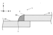
- FIG. 1A is an explanatory diagram schematically showing an example of the structure of a welded joint according to this embodiment.
- FIG. 1A a coordinate system such as that shown in FIG. 1A will be used below for appropriate explanation.
- FIG. 1A a welded joint obtained by welding two steel plates by arc welding is illustrated as an example.
- a welded joint obtained by welding two steel plates by laser welding also has the same configuration as in FIG. 1A, although the detailed shape of the weld bead portion is different.
- FIG. 1A schematically shows the overall configuration of a welded joint obtained by lap fillet welding a first steel plate and a second steel plate by arc welding.
- Figure 3 shows a cross-section of the welded joint perpendicular to the stretch direction;
- the welded joint 1 according to this embodiment includes a first steel plate 10, a second steel plate 20, and a weld bead portion 30. As shown in FIG.
- the material for at least one of the first steel plate 10 and the second steel plate 20 forming the weld joint 1 it is preferable to use various plated steel plates. It is more preferable to use a plated steel sheet having a plated layer as described in detail below as the material for both.
- the weld bead portion 30 is a portion formed by arc welding, and is composed of a welding wire used as necessary during welding and the first steel plate 10 and the second steel plate 20 as materials. Interdiffusion of elements occurs.
- the weld bead portion 30 is formed by oxidizing such diffusion elements. Therefore, in FIG. 1A, the joint interface between the weld bead portion 30 and the first steel plate 10 or the second steel plate 20 is shown as a plane (using a straight line) for convenience of illustration, but the actual joint interface is It has a complicated curved surface.
- the weld bead portion 30 extends along the Y-axis direction in the figure, and the first steel plate 10 and the second steel plate 20 are joined by the weld bead portion 30 .
- such a weld bead portion 30 is generally composed mainly of an oxide of an element that is easily oxidized among the various elements that constitute the plated steel sheet as a material. Examples of such easily oxidizable elements include Al and Mg.
- the measurement may be performed, for example, as follows. That is, a sample having a weld bead portion 30 is prepared, the sample is cut in a plane (XZ plane in FIG. 1A) perpendicular to the welding direction (Y-axis direction in FIG. 1A), and a cross section of the weld bead portion 30 The sample is embedded in resin and polished so that (XZ cross section in FIG. 1A) can be observed.
- a scanning electron microscope SEM
- SEM-EDS Energy Dispersive x-ray Spectroscopy
- the oxides generated during welding are roughly divided into two types: scale and slag.
- the scale contains 50% or more of Fe in mass % when oxygen is excluded, and the balance is composed of easily oxidizable elements and impurities.
- the slag contains 50% or more of easily oxidizable elements in terms of mass% when oxygen is excluded, and the balance is less than 50% by mass of Fe and impurities.
- the “easily oxidizable element” is a metal element that is more easily oxidized than Fe in the Ellingham diagram, and is a metal element that can be added to the plating layer. Specific examples of such easily oxidizable metal elements include Ca, In, Bi, Cr, Zr, Li, La, Ce, Sr, Y, Si, Mn, Al, and Ti.
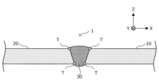
- the point where the surface of the base metal and the surface of the weld bead intersect is defined as the "toe”.
- the point where the surface of the weld bead portion 30 and the surface of the first steel plate 10 or the second steel plate 20 intersect corresponds to such a "toe”.
- the welded joint 1 according to this embodiment focuses on the corrosion resistance in the vicinity of the toe T. As shown in FIG.
- toe T is not limited to lap fillet welded joints as shown in FIG. 1A, butt welded joints such as shown in FIG. Welded joints and the like are also specified in the same way.
- FIG. 2 is a diagram schematically showing a cross section of the welded joint 1 perpendicular to the extending direction of the weld bead portion 30. As shown in FIG.
- a portion of the welded joint 1 that is not heat-affected by welding is referred to as a "non-heat-affected zone".
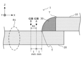
- a region R1 sufficiently separated from the vicinity of the toe T corresponds to such a non-heat-affected zone.
- the position of such a non-heat-affected zone is, for example, from the toe T as shown in FIG. can be considered as a region separated by, for example, 3 mm or more in the direction away from (the X-axis direction in FIG. 2).
- FIG. 3 is a diagram schematically showing a part of a cross section parallel to the plate thickness direction in the non-heat affected zone R1.
- the non-heat-affected zone R1 in at least one of the first steel sheet 10 or the second steel sheet 20 is, as schematically shown in FIG. It has a layer 103 and an oxide layer 105 located on the plated layer 103 .
- the plating layer 103 and the oxide layer 105 as described above may be present on one surface of the base iron 101. More preferably present on the surface.
- the base iron 101, the plating layer 103 and the oxide layer 105 will be described in detail below.
- the base iron 101 corresponding to the base material of the plated steel sheet, which is the material is not particularly limited.
- Various steel plates can be used as the base steel 101 depending on the mechanical strength (for example, tensile strength) required for the welded joint 1 .
- Examples of such steel sheets include various Al-killed steels, ultra-low carbon steels containing Ti, Nb, etc., high-strength steels containing ultra-low-carbon steels with strengthening elements such as P, Si, Mn, etc.
- Various steel plates such as can be mentioned.
- the thickness of the base iron 101 is not particularly limited, and is appropriately set according to the mechanical strength required for the welded joint 1 and the like.
- the plating layer 103 is provided on at least part of the surface of the base iron 101, and more preferably, is provided over the entire surface of the base iron 101, as schematically shown in FIG.
- the plated layer 103 is derived from the plated layer of the plated steel sheet that is the material of the welded joint 1 . Below, first, the chemical composition of the plating layer 103 will be described in detail.
- the chemical composition of the plating layer 103 according to the present embodiment is, in mass %, Al: 1.00 to 80.00%, Mg: 1.00 to 20.00%, Fe: 0 .01 to 15.00%, Si: 0 to 10.00%, Ca: 0 to 4.00%, and the balance consists of Zn and impurities of 5.00% by mass or more. That is, in the chemical composition of the plating layer 103 according to the present embodiment, the contents of Al, Mg, Fe, Si, and Ca are within the above ranges, and the total of these contents is less than 100% by mass, and the balance is 5.00% by mass or more of Zn and impurities.
- Al is an element necessary for forming the main phase (Zn--Al--Mg alloy phase) of the plating layer 103 according to this embodiment.
- Al is contained in a predetermined content or more in order to ensure corrosion resistance of the non-heat-affected zone. If the Al content in the plating layer 103 is less than 1.00% by mass, the corrosion resistance of the non-heat-affected zone as described above cannot be ensured. Therefore, in the plating layer 103 according to this embodiment, the Al content is 1.00% by mass or more.
- the Al content is preferably 18.00% by mass or more, more preferably 35.00% by mass or more. When the Al content falls within the above range, it is possible to ensure the corrosion resistance of the non-heat affected zone.
- the Al content in the plating layer 103 exceeds 80.00% by mass, the Al phase that functions as a cathode increases excessively when placed in a corrosive environment, and corrosion of the base iron progresses. Therefore, the corrosion resistance of the non-heat-affected zone cannot be ensured. Therefore, in the plating layer 103 according to this embodiment, the Al content is 80.00% by mass or less.
- the Al content is preferably 60.00% by mass or less, more preferably 50.00% by mass or less.
- Mg is an element necessary for forming the main phase (Zn--Al--Mg alloy phase) of the plating layer 103 according to this embodiment.
- Mg is contained in a predetermined content or more in order to secure the corrosion resistance of the non-heat-affected zone. Therefore, in the plating layer 103 according to this embodiment, the Mg content is 1.00% by mass or more.
- the Mg content is preferably 5.00% by mass or more, more preferably 7.00% by mass or more. When the Mg content falls within the above range, it is possible to secure the corrosion resistance of the non-heat affected zone.
- the Mg content in the plating layer 103 exceeds 20.00% by mass, the anodic dissolution of the plating layer is likely to proceed when placed in a corrosive environment, so the corrosion resistance of the non-heat-affected zone is ensured. I can't. Therefore, in the plating layer 103 according to this embodiment, the Mg content is 20.00% by mass or less.
- the Mg content is preferably 15.00% by mass or less, more preferably 13.00% by mass or less. When the Mg content falls within the above range, it is possible to ensure the corrosion resistance of the non-heat-affected zone.
- Elements constituting the base iron 101 may be mixed into the plating layer 103 from the base iron 101 that is the base material.
- elements forming the base iron 101 are transferred to the plating layer 103 by mutual diffusion of elements due to solid-liquid reactions between the base iron 101 and the plating layer 103. Easier to mix. Due to such contamination of elements, a predetermined amount of Fe is contained in the plating layer 103, and the content is generally 0.01% by mass or more. If the mutual diffusion is promoted, the adhesion between the base iron 101 and the plating layer 103 is improved. From the viewpoint of improving the adhesion between the base iron 101 and the plating layer 103, the Fe content in the plating layer 103 is preferably 0.20% by mass or more.
- Fe may be intentionally added to the plating bath used when manufacturing the plating layer 103 within the range that does not impair the effects of the present invention.
- the Fe content in the plating layer 103 is 15.00% by mass or more, a high-melting intermetallic compound of Fe and Al is formed in the plating bath, and the high-melting intermetallic compound is dross. As such, it adheres to the plating layer and significantly deteriorates the appearance quality, which is not preferable.
- the Fe content in the plating layer 103 is set to 15.00% by mass or less by adjusting the Fe content in the plating bath.
- the Fe content in the plating layer 103 is more preferably 10.00% by mass or less.
- Si is an element capable of suppressing excessive growth of an Fe—Al intermetallic compound formed at the interface between the plating layer and the base iron and improving the adhesion between the plating layer and the base iron.
- the Si content is preferably 0.05% by mass or more, more preferably 0.20% by mass or more, in order to suppress excessive growth of the Fe—Al intermetallic compound.
- the Si content exceeds 10.00% by mass, an excessive amount of Mg and a high-melting-point intermetallic compound are formed, which inhibits the formation of an Al—Mg oxide film that has the effect of suppressing Zn evaporation. It becomes difficult to suppress Zn evaporation during welding.
- the Si content in the plating bath for producing the plating layer 103 is too high, the viscosity of the plating bath may increase more than necessary, and the plating workability may decrease. Therefore, by adjusting the Si content in the plating bath from the viewpoint of plating workability, the Si content in the plating layer 103 becomes 10.00% by mass or less.
- the Si content in the plating layer 103 is preferably 5.00% by mass or less, more preferably 2.00% by mass or less.
- Ca 0 to 4.00% by mass
- the plating layer 103 When Ca is contained in the plating layer 103, it forms an intermetallic compound phase with Al and Zn. Furthermore, when the plating layer 103 contains Si together with Ca, Ca forms an intermetallic compound with Si. Since these intermetallic compounds have a high melting point and a stable structure, it is possible to suppress the formation of blowholes and LME caused by Zn evaporation during welding of plated steel sheets. The effect of suppressing the formation of blowholes and LME during welding is exhibited by setting the Ca content to 0.01% by mass or more.
- the Ca content in the plating layer 103 is more preferably 0.10% by mass or more.
- the Ca content in the plating layer 103 exceeds 4.00% by mass, the corrosion resistance of the non-heat-affected zone is lowered. From this point of view, the Ca content in the plating layer 103 is 4.00% by mass or less.
- the Ca content in the plating layer 103 is preferably 2.50% by mass or less, more preferably 1.50% by mass or less.
- the balance of Al, Mg, Fe, Si, and Ca is Zn of 5.00% by mass or more and impurities.
- Zn is an element necessary for forming the main phase (Zn—Al—Mg alloy phase) of the plating layer 103 according to the present embodiment, and is an important element for improving the corrosion resistance of the non-heat-affected zone. be. Since the effect of improving the corrosion resistance of the non-heat-affected zone is manifested when the Zn content is 5.00% by mass or more, the Zn content is made 5.00% by mass or more.
- the plating layer 103 further selectively contains Sb: 0 to 0.500%, Pb: 0 to 0.500%, Cu: 0 to 1, instead of part of the remaining Zn. .000%, Sn: 0-1.000%, In: 0-1.000%, Bi: 0-1.000%, Ti: 0-1.000%, Cr: 0-1.000%, Nb Zr: 0-1.000% Ni: 0-1.000% Mn: 0-1.000% V: 0-1.000% Mo: 0-1.000% 000%, Ag: 0 to 1.000%, Li: 0 to 1.000%, La: 0 to 0.500%, Ce: 0 to 0.500%, B: 0 to 0.500%, Y: It may contain 0 to 0.500%, Sr: 0 to 0.500%, and a total of 0 to 5.000%.
- the plating layer 103 includes Sb, Pb, Cu, Sn, In, Bi, Ti, Cr, Nb, Zr, Ni, Mn, V, Mo, Ag, Li, La , Ce, B, Y, and Sr may be contained within the above content range and in a total content of 5.000% by mass or less. It should be noted that the plating layer 103 according to the present embodiment may not contain the optional additive elements as described above, so the lower limit of the content of each optional additive element is 0% by mass.
- the total content of the optional additive elements is preferably 1.000% by mass or less, more preferably 0.200% by mass or less. The content of each optional additive element will be described in detail below.
- the contents of Sb, Pb, and Sr in the plating layer 103 are each independently set to 0.500% by mass or less.
- the contents of Sb, Pb and Sr are each independently preferably 0.200% by mass or less.
- the effect of improving the corrosion resistance of the weld zone is exhibited when the content of any one of Cu, Ti, Cr, Nb, Ni, Mn, and V in the plating layer 103 is 0.005% by mass or more. Therefore, when at least one of Cu, Ti, Cr, Nb, Ni, Mn, and V is contained in the plating layer 103, the content of these elements is independently 0.005% by mass or more. preferably.
- the plating for forming the plated layer 103 in which any of the contents of Cu, Ti, Cr, Nb, Ni, Mn, and V exceeds 1.000% by mass, the plating for forming the plated layer 103 These elements tend to form various intermetallic compounds in the bath. As a result, the viscosity of the plating bath is increased, and a plated steel sheet with good plating properties cannot be produced. Therefore, the contents of Cu, Ti, Cr, Nb, Ni, Mn, and V in the plating layer 103 are each independently set to 1.000% by mass or less. The contents of Cu, Ti, Cr, Nb, Ni, Mn and V are each independently preferably 0.200% by mass or less.
- Sn, In, and Bi are elements that increase the Mg elution rate when the plating layer 103 containing Zn, Al, and Mg is placed in a corrosive environment. When the elution rate of Mg increases, Mg ions are supplied to the portion where the base iron is exposed, thereby improving anticorrosion properties. From this point of view, when Sn, In, and Bi are contained, the contents of Sn, In, and Bi are each independently set to 0.0050% by mass or more.
- the Zr content is 1.000% by mass or less.
- the Zr content is preferably 0.100% by mass or less.
- Mo 0 to 1.000% by mass
- the Mo content is 1.000% by mass or less.
- the Mo content is preferably 0.050% by mass or less.
- the Ag content is 1.000% by mass or less.
- the Ag content is preferably 0.050% by mass or less.
- Li 0 to 1.000% by mass
- the content is preferably 0.010% by mass or more.
- the content of Li is 1.000% by mass or less.
- the content of Li is preferably 0.050% by mass or less.
- La, Ce, and Y are elements that exhibit substantially the same effect as Ca, and suppress the formation of blowholes during welding. This is because the atomic radius of each element is close to the atomic radius of Ca. When these elements are contained in the plating layer 103, they are substituted at Ca sites. Therefore, these elements are detected at the same position as Ca in EDS. Moreover, even when these elements become oxides, the oxides of these elements are detected at the same position as CaO.
- the effect of suppressing the formation of blowholes during welding is expressed by independently setting the content of these elements to 0.010% by mass or more. Therefore, the contents of La, Ce, and Y in the plated layer 103 are more preferably independently 0.050% by mass or more.
- the contents of La, Ce, and Y are each independently 0.500% by mass or less.
- the contents of La, Ce, and Y are each independently preferably 0.100% by mass or less.
- B 0 to 0.500% by mass
- B When B is contained in the plating layer 103, it has the effect of further suppressing LME. It is presumed that this is because when B is contained in the plating layer 103, it combines with at least one of Zn, Al, Mg, and Ca to form various intermetallic compound phases.
- B the presence of B in the plating layer 103 causes B to diffuse from the plating layer 103 to the base iron 101, and has the effect of further suppressing the LME of the base iron 101 by grain boundary strengthening.
- various intermetallic compounds formed with B have extremely high melting points, it is presumed that they also act to suppress Zn evaporation during welding. These improvement effects are exhibited by containing 0.050% by mass or more of B. Therefore, the content of B in the plating layer 103 is more preferably 0.050% by mass or more.
- the melting point of the plating will rise sharply and the workability of the plating will decrease, producing a plated steel sheet with excellent plating properties. Can not do it. Since such deterioration of the plating workability becomes remarkable when the content of B exceeds 0.500% by mass, the content of B is made 0.500% by mass or less.
- the content of B is preferably 0.10% by mass or less.
- the chemical composition of the plating layer 103 can be measured using ICP-AES (Inductively Coupled Plasma Atomic Emission Spectrometry) or ICP-MS (Inductively Coupled Plasma Mass Spectrometry).
- ICP-AES Inductively Coupled Plasma Atomic Emission Spectrometry
- ICP-MS Inductively Coupled Plasma Mass Spectrometry
- a non-heat-affected zone of interest is immersed in a 10% HCl aqueous solution containing an inhibitor for about 1 minute to peel off the plated layer and prepare a solution in which the plated layer is dissolved.
- the resulting solution can be analyzed by ICP-AES or ICP-MS to obtain the overall average chemical composition of the plated layer.
- the plating layer 103 according to the present embodiment has the chemical composition as described above, and a more preferable chemical composition is as follows. That is, the plating layer 103 according to the present embodiment contains at least 18.00 to 60.00% by mass of Al and 5.00 to 15.00% by mass of Mg as a chemical composition, and if necessary Furthermore, it is more preferable to further contain the optional additive elements as described above.
- the plating layer 103 contains at least 35.00 to 60.00% by mass of Al and 7.00 to 15.00% by mass of Mg as a chemical composition, and if necessary It is even more preferable that the plated layer 103 further contains an optional additive element as described above and further contains a Mg 32 (Al, Zn) 49 phase.
- the Mg 32 (Al, Zn) 49 phase has a Mg content [Mg], a Zn content [Zn], and an Al content [Al] contained in the grains of the Mg 32 (Al, Zn) 49 phase.
- the chemical composition of the Mg 32 (Al, Zn) 49 phase is preferably measured using TEM-EDX (Transmission Electron Microscope-Energy Dispersive X-ray Spectroscopy).
- the Mg 32 (Al, Zn) 49 phase may be detected as both a crystalline phase as well as a quasicrystalline phase. In the case of the crystal phase, it is possible to identify that the crystal structure is the Mg 32 (Al, Zn) 49 phase from the electron beam diffraction image in TEM observation.
- Mg 32 (Al, Zn) 49 phase is a quasicrystalline phase
- an electron beam diffraction image is photographed by TEM, and it is confirmed whether or not a five-fold symmetrical crystal structure is observed in the electron beam diffraction image. can do.
- a five-fold symmetrical crystal structure can be determined by obtaining an electron beam diffraction image called a Penrose pattern.
- the Mg 32 (Al, Zn) 49 phase exerts a sacrificial anti-corrosion property on the plated steel sheet, thereby suppressing the corrosion of the base iron from the cut parts and welded parts where the base iron is exposed, and has the effect of improving the red rust resistance.
- the Mg 32 (Al , Zn) 49 phase itself has excellent corrosion resistance . It also has the effect of improving the corrosion resistance after painting from the viewpoint of the film swelling width.
- the deposition amount of the plating layer 103 as described above is not particularly specified, it is, for example, about 15 to 250 g/ m2 per side of the base iron 101. preferable.
- the adhesion amount of the plating layer 103 within the above range, the non-heat-affected zone of the welded joint 1 according to the present embodiment can exhibit sufficient corrosion resistance.
- the adhesion amount of the plating layer 103 is measured as follows. First, a sample having a size of 30 mm ⁇ 30 mm is cut out from a plated steel sheet, and the mass of the sample is measured in advance. A tape seal is attached to one surface of this sample so that the plated layer on this one surface will not be dissolved in the next step. After that, the sample is immersed in a 10% HCl aqueous solution to which an inhibitor has been added to remove the plating layer by pickling, and the mass of the sample after pickling is measured. It is possible to determine the adhesion amount of the plating layer 103 per side from the change in mass of the sample before and after pickling.
- an oxide layer 105 is located on the surface of the plated layer 103 as described above.
- the oxide layer 105 is derived from the oxide layer of the plated steel sheet that is the material of the welded joint 1 .
- an easily oxidizable element among the elements constituting the plating layer 103 reacts with oxygen in the heat treatment atmosphere in the cooling treatment for solidifying the plating layer performed during the production of the plated steel sheet.
- the oxide layer 105 is composed mainly of oxides of the elements that constitute the plating layer 103 , so its chemical composition changes according to the elements contained in the plating layer 103 .
- the oxide layer 105 contains Zn oxide, Mg oxide and Al oxide in total of 50% by mass or more, and furthermore, these Zn, Mg and Al hydroxides and other constituent elements in the plating layer 103 It is speculated that the layer may contain at least one of oxides or hydroxides of , impurities, and the like.
- the oxide layer 105 exists in the following specific state by going through a specific heat treatment process as detailed below when manufacturing the plated steel sheet that is the material. This state will be described in detail below with reference to FIGS. 4 and 5.
- FIG. FIG. 4 is a diagram schematically showing a part of a cross section parallel to the plate thickness direction of the oxide layer.
- FIG. 5 is an explanatory diagram for explaining the intensity of peaks in the XPS measurement results.
- the oxide layer 105 according to the present embodiment is manufactured through a specific heat treatment process as described in detail below when manufacturing a plated steel sheet as a material, so that at least one of Zn oxide and hydroxide A dense coating in which the total amount of at least one of Al oxide or hydroxide and at least one of Mg oxide or hydroxide is greater than the amount of It's becoming More specific description will be given below.
- FIG. 4 attention is paid to a position ("position A” in FIG. 4) at a depth of 5 nm from the outermost surface of the oxide layer 105.
- FIG. 1 when such positions are observed by X-ray photoelectron spectroscopy (XPS), peaks attributed to Al—O bonds, Mg—O bonds, and Zn—O bonds, respectively
- XPS X-ray photoelectron spectroscopy
- the value of the intensity ratio ([Al--O]+[Mg--O])/[Zn--O] calculated from the intensity of is preferably 5.0 or more.
- the outermost surface of the oxide layer 105 may have contaminants such as oils and fats. Therefore, it is desired that the XPS measurement as described above be performed in a state where such stains and the like do not exist. From this point of view, the surface of the oxide layer 105 is subjected to a treatment such as ultrasonic cleaning in ethanol to remove stains and the like, and the surface obtained by such treatment is subjected to XPS measurement as described above. It is referred to as "the outermost surface of the oxide layer 105".
- XPS measurement conditions may be, for example, as follows.
- X-ray source mono-Al K ⁇ (1486.6 eV)
- X-ray diameter 50-200 ⁇ m
- Measurement area 100-700 ⁇ m ⁇ 100-700 ⁇ m
- Degree of vacuum 1 ⁇ 10 ⁇ 10 to 1 ⁇ 10 ⁇ 11 torr (1 torr is 133.32 Pa.
- Accelerating voltage 1 to 10 kV
- the bonds described above are characteristic bonds of oxides and hydroxides of Al, Mg, and Zn. It can be considered that the intensity of the peak attributed to these bonds has a positive correlation with the abundance of at least one of the oxides and hydroxides of Al, Mg, and Zn.
- the peak attributed to the Al—O bond is the peak observed within the range of 72 to 76 eV in the XPS spectrum focusing on Al 2p3/2.
- the peak attributed to the Mg—O bond is the peak observed within the range of 48 to 52 eV in the XPS spectrum focusing on Mg2p3/2.
- the peak attributed to the Zn—O bond is the peak observed within the range of 1018 to 1024 eV in the XPS spectrum focusing on Zn2p3/2.
- the intensity of the peak attributed to each bond is obtained by considering the baseline of the peak of interest in the XPS spectrum as schematically shown in FIG . Let I b be subtracted (ie, “I p ⁇ I b ”).
- a more detailed method for calculating the intensity ratio is as follows. That is, XPS is measured as described above at an arbitrary location on the surface corresponding to the position of 5 nm deep from the outermost surface obtained as described above (the surface of "position C" in FIG. 4). , the intensity ratio ([Al--O]+[Mg--O])/[Zn--O] is calculated. Such measurement/calculation processing is performed at any five locations on the surface corresponding to “position A”, and the average value of the five intensity ratios obtained is calculated as , intensity ratio ([Al--O]+[Mg--O])/[Zn--O].
- a dense film is formed such that the value of the strength ratio is 5.0 or more, so that Zn evaporation during welding can be suppressed. Blowhole formation can be suppressed. If the value of the intensity ratio is less than 5.0, the density required for the oxide layer 105 may be insufficient.
- the intensity ratio value is more preferably 10.0 or more.
- the upper limit of the strength ratio ([Al--O]+[Mg--O])/[Zn--O] is not particularly defined, but about 100.0 is a substantial upper limit.
- the thickness (more specifically, the average thickness) of the oxide layer 105 as described above is not particularly defined, but is, for example, about 0.05 to 2.00 ⁇ m per side of the base iron 101. is preferred.
- the non-heat-affected zone according to the present embodiment can sufficiently suppress the formation of blowholes due to Zn evaporation during welding.
- the oxide layer 105 having the thickness as described above is obtained by performing a heat treatment process as described in detail below while controlling the threading speed of the steel sheet in an appropriate range when manufacturing the plated steel sheet as a material. , is realized.
- the thickness of the oxide layer 105 can be measured using XPS. XPS measurement is performed from the surface of the plated steel sheet in the depth direction at a pitch of 1 to 3 nm, and the depth until the maximum intensity of oxygen is 1/20 of the maximum intensity of the outermost surface is defined as the thickness of the oxide layer. As for the XPS measurement conditions, the same conditions as described above may be used.
- the non-heat-affected zone in the welded joint 1 according to the present embodiment has been described in detail above with reference to FIGS. 2 to 5.
- FIG. The non-heat-affected zone of the welded joint 1 according to this embodiment may further have one or more layers of various coatings on the oxide layer 105 described above. Examples of such films include chromate films, phosphate films, chromate-free films, organic resin films, and the like.
- FIG. 1 uses the plated steel sheet having the plated layer and the oxide layer as described above as a material for at least one of the first steel sheet 10 and the second steel sheet 20, so that the welded joint 1 is Even so, a phase functioning as metallic Zn can remain in the plating layer existing in the vicinity of the toe. As a result, in the welded joint 1 according to this embodiment, the corrosion resistance in the vicinity of the toe can be improved.
- the plated layer 103 present in the region R2 has at least one of ⁇ -Zn phase, MgZn 2 phase, Mg 2 Zn 3 phase, and MgZn phase as the metal Zn-containing phase having an equivalent circle diameter of 0.5 ⁇ m or more. have.
- the ⁇ -Zn phase, MgZn 2 phase, Mg 2 Zn 3 phase, and MgZn phase are not oxides of Zn, but phases composed of Zn alone or alloys of Zn and other metals.
- these metal phases When these metal phases are present in a state having an equivalent circle diameter of 0.5 ⁇ m or more, these metal phases function as metal Zn, and the sacrificial anti-corrosion ability of metal Zn can be exhibited.
- the presence or absence of the metal Zn-containing phase having an equivalent circle diameter of 0.5 ⁇ m or more can be confirmed by observing the cross section of the region R2 with an SEM. Further, whether the metallic Zn-containing phase of interest is the ⁇ -Zn phase, the MgZn 2 phase, the Mg 2 Zn 3 phase, or the MgZn phase can be determined by, for example, a cross-sectional SEM-EPMA (Electron Probe Micro Analyzer). ) device, the composition (unit: atomic %) of the phase to be analyzed in the field of view is obtained by point analysis, and the composition can be specified as follows.
- ⁇ -Zn phase Zn 98% or more, total of other elements 2% or less ⁇ MgZn 2 phase: Zn 60% or more and 70% or less, Mg 30% or more and less than 40% ⁇ Mg 2 Zn 3 phase: Zn 55% or more and less than 60%, Mg 40 % or more and less than 45% MgZn phase: Zn 45% or more and less than 55%, Mg 45% or more and 55% or less
- the upper limit of the equivalent circle diameter of the metal Zn-containing phase is not particularly specified, the upper limit is substantially about 200.0 ⁇ m.
- FIG. 6 is an explanatory diagram for explaining the welded joint according to the present embodiment, in which the region R2 is arranged in a direction ( 6 schematically shows a state when a cross section (XZ cross section in FIG. 6) cut in the X-axis direction) is observed with an electron microscope (SEM).
- SEM electron microscope
- the length of the interface between the base iron 101 and the plating layer 103 (more specifically, the length in the X-axis direction) is defined as Le .
- the length (projection length) in the X-axis direction when each of the metal Zn-containing phases 111 in the plating layer 103 is projected onto the interface is defined as Li (where i is an integer equal to or greater than 1).
- i is an integer equal to or greater than 1).
- the metallic Zn-containing phase 111 may include phases other than the Mg--Zn phase represented by the ⁇ -Zn phase, MgZn 2- phase, Mg 2 Zn 3- phase, and MgZn phase.
- the metal Zn-containing phase 111 is composed of approximately ⁇ -Zn phase, MgZn 2 phase, Mg 2 Zn 3 phase, MgZn phase. Therefore, the total projected length Lt of the metal Zn-containing phase 111 is considered to be substantially the sum of the projected lengths of the ⁇ -Zn phase, the MgZn 2 phase, the Mg 2 Zn 3 phase, and the MgZn phase. be able to.
- the phase functioning as metal Zn sufficiently remains in the vicinity of the toe of the welded joint 1 according to the present embodiment, and the corrosion resistance of the vicinity of the toe is further improved. becomes possible. That is, the ratio (L t /L e ) as described above can also be regarded as an index of the average existence ratio of the metallic Zn-containing phase 111 in the region R2. In the vicinity of the toe of the welded joint 1 according to this embodiment, the ratio (L t /L e ) is preferably 20% or more, more preferably 35% or more. On the other hand, the upper limit of the ratio (L t /L e ) is not particularly defined, and the larger the value, the better, but the practical upper limit is 100%. In addition, in the cross section of the region R2 as shown in FIG. 6, the remainder of the metallic Zn-containing phase 111 is the Fe—Al intermetallic compound phase 113 and impurities.
- the above ratio (L t /L e ) can be specifically calculated as follows. That is, at a magnification of 500 to 2500 times, observation is made on five arbitrary fields of view of 80 to 160 ⁇ m ⁇ 80 to 160 ⁇ m in size. In each field of view, the distribution of Zn and Mg was measured by cross-sectional SEM-EDS mapping to identify the distribution of ⁇ -Zn phase, MgZn 2 phase, Mg2Zn3 phase, and MgZn phase. Calculate the ratio (L t /L e ). A value obtained by averaging the ratio obtained from each field of view for the number of fields of view (5 fields of view) is defined as the ratio (L t /L e ) in the present embodiment.
- the welded joint 1 according to the present embodiment has been described in detail above with reference to FIGS. 1A to 6.
- the welded joint 1 according to this embodiment as described above can be suitably used, for example, as a vehicle underbody part.
- the plated steel sheet which is the material for the welded joint 1 according to the present embodiment, uses the steel sheet made of the base iron 101 as described above as a base material, and forms the plating layer 103 and the oxide layer 105 on the surface of the base iron 101.
- a thermal spraying method, a cold spraying method, a sputtering method, a vapor deposition method, an electroplating method, or the like can be applied.
- the hot dip plating method is most preferable in terms of cost.
- the obtained plated steel sheet (plated steel sheet composed of the base iron 101 and the plating layer 103) is subjected to a specific heat treatment process as described below, so that the oxide layer 105 is formed on the surface of the plating layer 103. Form.
- a plated steel sheet that is used as a material for the welded joint 1 according to this embodiment can be manufactured.
- a manufacturing method for obtaining the plated steel sheet according to the present embodiment using a hot dip plating method will be described below in detail.
- a steel sheet made of the base iron 101 used as a base material is rolled by the Sendzimir method to a desired thickness, then wound into a coil shape and installed in a hot dip coating line.
- the steel sheet In the hot-dip plating line, the steel sheet is continuously passed while being drawn out from the coil. At that time, the steel sheet is heated and reduced at 800 ° C. in an N 2 -5% H 2 gas atmosphere in an environment where the oxygen concentration is 20 ppm or less where oxidation is difficult to occur, for example, by the annealing equipment provided on the line. . Then, it is air-cooled with N2 gas to about +20°C of the bath temperature of the subsequent plating bath, and immersed in the plating bath.
- the plating bath prepare a plating alloy in a molten state that has the chemical components described above.
- the temperature of the plating bath should be above the melting point of the plating alloy (for example, about 460 to 600° C.).
- a pure metal purity of 99% or more
- the alloy material it is preferable to use a pure metal (purity of 99% or more) as the alloy material.
- a predetermined amount of the alloy metal is mixed so that the composition of the plating layer as described above is obtained, and the alloy is completely melted using a high-frequency induction furnace or an arc furnace in a vacuum or in an inert gas replacement state. and Furthermore, the alloy mixed with the predetermined components (the composition of the plating layer) is melted in the atmosphere, and the resulting melt is used as a plating bath.
- the plating amount is controlled by, for example, N2 wiping gas so that the plating layer 103 to be formed has a desired thickness.
- N2 wiping gas for conditions other than the bath temperature, general plating operation conditions may be applied, and no special equipment or conditions are required.
- first cooling process and second cooling process are performed on the molten plating alloy located on the steel sheet, and the molten plating alloy is formed into the plating layer 103.
- An oxide layer 105 is formed on the surface of the plating layer 103 .
- the first cooling step is a cooling step that is performed when the temperature of the plated alloy is in the range of 250 ° C. or higher below the bath temperature, and the plated steel sheet in the above temperature range is cooled to a dew point of -20 ° C. Rapidly cool at an average cooling rate of 10° C./second or more in the following atmosphere.
- the hot-dip plating method is adopted in the plating process, the first cooling process is performed immediately after the steel sheet comes out of the plating bath. As a result, the plating alloy positioned on the surface of the steel sheet is solidified to form a plating layer.
- the second cooling step is performed.
- This second cooling step is a step of slowly cooling the plated steel sheet within a temperature range of less than 250°C to 50°C or more in an atmosphere with a dew point of 0°C or more at an average cooling rate of less than 10°C/sec.
- a desired oxide layer is formed by controlling the state of the oxide formed on the surface of the plating layer.
- the surface of the plating layer 103 is rapidly cooled in a temperature range of 250°C or more below the bath temperature, and slowly cooled in a temperature range of 50°C or more below 250°C. , a dense oxide layer 105 is formed that satisfies specific conditions in the XPS measurement results.
- the interval from the end of the first cooling step to the start of the second cooling step is preferably within 3 seconds, and the second cooling step is started immediately after the first cooling step is finished. is preferred. If the interval between the end of the first cooling process and the start of the second cooling process exceeds 3 seconds, an unintended cooling process occurs and the desired oxide layer 105 cannot be achieved.
- the lower limit of the dew point is not particularly specified, but about -90°C is a substantial lower limit, for example.
- the average cooling rate is more preferably 40° C./second or more.
- the upper limit of the average cooling rate is not particularly specified, for example, about 90° C./second is the substantial upper limit.
- the upper limit of the dew point is not particularly specified, but for example, about 20°C is the substantial upper limit. Also, the average cooling rate is more preferably 4° C./sec or less.
- the desired oxide layer 105 cannot be realized if either the first cooling process or the second cooling process as described above is not performed. By performing both the first cooling process and the second cooling process as described above, the oxide layer 105 according to this embodiment can be realized.
- an alloying heat treatment step for example, a heat treatment step involving heating to a reaching plate temperature of about 480 to 550 ° C., which is generally performed in the production of galvannealed steel sheets
- the state of oxide formation controlled by the first cooling step and the second cooling step is disrupted, and as a result, the oxide grows excessively. can't get From this point of view, it is important not to perform the heat treatment process after the second cooling process.
- cooling gas other than the N2 gas, a gas having a high heat removal effect such as He gas or hydrogen gas may be used.
- a contact thermocouple K-type
- K-type a contact thermocouple
- the average temperature of the entire coating layer can be constantly monitored.
- various speeds and thicknesses and unifying various operating conditions such as the preheating temperature of the steel sheet and the temperature of the hot dip plating bath
- the temperature of the entire coating layer at that point in time under these manufacturing conditions can be reduced to Nearly accurate monitoring is possible.
- the surface temperature of the plating layer may be measured by a non-contact radiation thermometer, although it is not as accurate as the contact type.
- the relationship between the surface temperature of the plating layer and the average temperature of the entire plating layer may be obtained by a simulation that performs heat conduction analysis. Specifically, the preheating temperature of the steel sheet, the temperature of the hot dip coating bath, the speed at which the steel sheet is lifted from the coating bath, the thickness of the steel sheet, the layer thickness of the coating layer, the amount of heat exchanged between the coating layer and manufacturing equipment, and the thickness of the coating layer.
- the surface temperature of the plating layer and the average temperature of the entire plating layer are obtained based on various manufacturing conditions such as the amount of heat dissipation. After that, using the obtained results, the relationship between the surface temperature of the plating layer and the average temperature of the entire plating layer may be obtained.
- a treatment for forming one or more layers of various films may be performed.
- treatments include chromate treatment, phosphate treatment, chromate-free treatment, and organic resin film-forming treatment.
- Chromate treatment includes electrolytic chromate treatment, in which a chromate film is formed by electrolysis, reactive chromate treatment, in which a film is formed by using a reaction with the material, and then excess treatment liquid is washed away, and treatment liquid is applied and washed with water.
- electrolytic chromate treatment in which a chromate film is formed by electrolysis
- reactive chromate treatment in which a film is formed by using a reaction with the material, and then excess treatment liquid is washed away, and treatment liquid is applied and washed with water.
- coating-type chromate treatment that forms a film by drying without drying, and any chromate treatment may be employed.
- electrolytic chromate treatment examples include chromic acid, silica sol, resin (phosphoric acid resin, acrylic resin, vinyl ester resin, vinyl acetate acrylic emulsion, carboxylated styrene-butadiene latex, diisopropanolamine-modified epoxy resin, etc.), and hard silica.
- resin phosphoric acid resin, acrylic resin, vinyl ester resin, vinyl acetate acrylic emulsion, carboxylated styrene-butadiene latex, diisopropanolamine-modified epoxy resin, etc.
- hard silica can be exemplified by electrolytic chromate treatment using
- phosphate treatment examples include zinc phosphate treatment, zinc calcium phosphate treatment, and manganese phosphate treatment.
- Chromate-free treatment is particularly suitable because it does not burden the environment.
- Such chromate-free treatment includes electrolytic chromate-free treatment in which a chromate-free film is formed by electrolysis, reaction-type chromate-free treatment in which a film is formed by using a reaction with the material, and then excess treatment liquid is washed away, and treatment liquid is applied.
- the organic resin used for the organic resin film forming treatment is not limited to a specific resin. Resin can be used.
- modified product refers to a reactive functional group contained in the structure of these resins, and another compound (for example, a monomer, a cross-linking agent, etc.) containing a functional group capable of reacting with the functional group in the structure. It refers to the resin that has been reacted.
- organic resin one type of the above may be used alone, or two or more types of organic resins (non-modified) may be mixed and used. Also, one or a mixture of two or more organic resins obtained by modifying at least one other organic resin in the presence of at least one organic resin may be used. Alternatively, a water-based organic resin may be used by dissolving or dispersing it in water. Further, such an organic resin film may contain various coloring pigments and antirust pigments.
- the welded joint according to the present embodiment uses the plated steel sheet manufactured as described above as a material for at least one of the first steel sheet and the second steel sheet when manufacturing the welded joint, and the first steel sheet and the second steel sheet. It is manufactured by arranging the second steel plate so as to obtain the desired shape of the welded joint and welding the first steel plate and the second steel plate.
- arc welding or laser welding can be used to weld the first steel plate and the second steel plate.
- arc welding or laser welding can be used to weld the first steel plate and the second steel plate.
- the first steel plate and the second steel plate may be welded under the following welding conditions, for example.
- Welding current 250 A
- welding voltage 26.4 V
- welding speed 100 cm/min
- Welding gas 20% CO 2 +Ar
- gas flow rate 20 L/min
- Welding wire YGW16 Nippon Steel Welding Co., Ltd. ⁇ 1.2 mm (C: 0.1% by mass, Si: 0.80% by mass, Mn: 1.5% by mass, P: 0.015% by mass, S: 0.008% by mass, Cu: 0.36% by mass)
- Welding torch tilt angle 45°
- the first steel plate and the second steel plate may be welded under the following welding conditions, for example.
- the welded joint according to the present invention will be specifically described while showing examples and comparative examples.
- the examples shown below are merely examples of the welded joint according to the present invention, and the welded joint according to the present invention is not limited to the examples shown below.
- a hot-rolled steel sheet with a thickness of 3.2 mm (0.05% by mass C-0.007% by mass Si-0.25% by mass Mn, NIPPON STEEL Co., Ltd.) was used.
- the hot-rolled steel sheet was cut into a size of 100 mm ⁇ 200 mm to obtain a test piece.
- Plating baths for realizing a plating layer having a composition as shown in Table 1 below were prepared and installed in a batch-type hot-dip plating test apparatus manufactured in-house, and plating was applied to the above test pieces.
- the temperature of the test piece was measured using a thermocouple spot-welded to the center of the test piece.
- the surface of the plating base plate is heat-reduced at 800 ° C. bottom. After the heat reduction treatment, the test piece was air-cooled with N2 gas, and after the temperature of the test piece reached +20°C of the bath temperature, the test piece was immersed in the plating bath of the hot-dip plating test apparatus for about 3 seconds.
- the test piece After immersion in the plating bath, the test piece was pulled up at a pulling speed of 20 to 200 mm/sec. At the time of pulling, N2 wiping gas was used to control the desired coating weight. In the following examples and comparative examples, the coating weight was controlled so that the coating weight of the dried plating layer per side of the test piece was 15 to 250 g/m 2 . After pulling up the test piece from the plating bath, the test piece was cooled from the plating bath temperature to room temperature under the conditions shown in Table 1 below. In the examples and comparative examples shown below, the second cooling process was started immediately after the end of the first cooling process (that is, the interval from the end of the first cooling process to the start of the second cooling process was 0.2 seconds or less).
- a steel plate with a size of 30 mm ⁇ 30 mm is cut from the test piece plated as described above, and the plated steel plate is immersed in a 10% HCl aqueous solution to which an inhibitor is added to pickle and peel the plating layer.
- the composition of the plating layer was measured by ICP analysis of the eluted elements.
- an electron beam diffraction image was taken by TEM, and based on whether or not a five-fold symmetrical crystal structure was observed in the electron beam diffraction image, the Mg 32 (Al, Zn) 49 phase Checked for presence.
- the XPS spectrum of the obtained oxide layer was measured according to the above method, and the value of the intensity ratio ([Al--O]+[Mg--O])/[Zn--O] was calculated.
- the obtained intensity ratio was evaluated based on the following criteria. ⁇ Evaluation Criteria ⁇ Rating "A”: value of strength ratio is 10.0 or more "B”: value of strength ratio is 5.0 or more and less than 10.0 "C”: value of strength ratio is less than 5.0
- a steel plate cut into a size of 150 mm ⁇ 50 mm was used as the first steel plate, and a steel plate cut into a size of 150 mm ⁇ 30 mm was used as the second steel plate.
- the long sides of these steel plates were overlapped and welded by arc welding (lap fillet welding) to form a welded joint.
- welding conditions in arc welding are as follows. Welding current: 250 A, welding voltage: 26.4 V, welding speed: 100 cm/min Welding gas: 20% CO 2 +Ar, gas flow rate: 20 L/min Welding wire: YGW16 Nippon Steel Welding Co., Ltd. ⁇ 1.2 mm (C: 0.1% by mass, Si: 0.80% by mass, Mn: 1.5% by mass, P: 0.015% by mass, S: 0.008% by mass, Cu: 0.36% by mass) Welding torch tilt angle: 45° Overlap allowance: 10mm Steel plate size: upper plate side (first steel plate) 150 x 50 mm, lower plate side (second steel plate) 150 x 30 mm Gap: 0mm
- Welding conditions in laser welding are as follows. Output: 7 kW, Welding speed: 400 cm/min, Forward/backward angle: 0° Steel plate size: upper plate side (first steel plate) 150 x 50 mm, lower plate side (second steel plate) 150 x 30 mm Overlap allowance: 10mm Gap: 0mm
- Red rust generation timing is over 60 cycles
- AA Red rust generation timing is over 30 cycles and 60 cycles or less
- A Red rust generation timing is over 15 cycles and 30 cycles or less
- B Red rust generation timing is 15 cycles the following
- first steel plate 20 second steel plate 30 weld bead portion 101 base iron 103 plating layer 105 oxide layer 111 metal Zn-containing phase 113 Fe—Al intermetallic compound phase T toe
Landscapes
- Chemical & Material Sciences (AREA)
- Engineering & Computer Science (AREA)
- Mechanical Engineering (AREA)
- Materials Engineering (AREA)
- Organic Chemistry (AREA)
- Metallurgy (AREA)
- Chemical Kinetics & Catalysis (AREA)
- Physics & Mathematics (AREA)
- Optics & Photonics (AREA)
- Plasma & Fusion (AREA)
- General Engineering & Computer Science (AREA)
- Coating With Molten Metal (AREA)
- Laser Beam Processing (AREA)
- Arc Welding In General (AREA)
Priority Applications (6)
| Application Number | Priority Date | Filing Date | Title |
|---|---|---|---|
| JP2023535054A JP7328608B1 (ja) | 2022-01-31 | 2023-01-26 | 溶接継手 |
| KR1020247026574A KR20240134171A (ko) | 2022-01-31 | 2023-01-26 | 용접 조인트 |
| EP23747034.9A EP4414476A4 (en) | 2022-01-31 | 2023-01-26 | Welded joint |
| CN202380017726.3A CN118696144A (zh) | 2022-01-31 | 2023-01-26 | 焊接接头 |
| US18/716,435 US20250035139A1 (en) | 2022-01-31 | 2023-01-26 | Welded joint |
| MX2024007671A MX2024007671A (es) | 2022-01-31 | 2023-01-26 | Junta soldada. |
Applications Claiming Priority (2)
| Application Number | Priority Date | Filing Date | Title |
|---|---|---|---|
| JP2022013460 | 2022-01-31 | ||
| JP2022-013460 | 2022-01-31 |
Publications (1)
| Publication Number | Publication Date |
|---|---|
| WO2023145824A1 true WO2023145824A1 (ja) | 2023-08-03 |
Family
ID=87471552
Family Applications (1)
| Application Number | Title | Priority Date | Filing Date |
|---|---|---|---|
| PCT/JP2023/002441 Ceased WO2023145824A1 (ja) | 2022-01-31 | 2023-01-26 | 溶接継手 |
Country Status (7)
| Country | Link |
|---|---|
| US (1) | US20250035139A1 (https=) |
| EP (1) | EP4414476A4 (https=) |
| JP (1) | JP7328608B1 (https=) |
| KR (1) | KR20240134171A (https=) |
| CN (1) | CN118696144A (https=) |
| MX (1) | MX2024007671A (https=) |
| WO (1) | WO2023145824A1 (https=) |
Cited By (4)
| Publication number | Priority date | Publication date | Assignee | Title |
|---|---|---|---|---|
| JP7541278B1 (ja) * | 2022-12-26 | 2024-08-28 | 日本製鉄株式会社 | 溶接継手 |
| WO2025234086A1 (ja) * | 2024-05-10 | 2025-11-13 | 日本製鉄株式会社 | 溶接継手 |
| WO2025234091A1 (ja) * | 2024-05-10 | 2025-11-13 | 日本製鉄株式会社 | 溶接継手 |
| TWI919679B (zh) | 2024-05-14 | 2026-03-21 | 日商杰富意鋼鐵股份有限公司 | 接合體及其製造方法 |
Citations (5)
| Publication number | Priority date | Publication date | Assignee | Title |
|---|---|---|---|---|
| JP2011208264A (ja) * | 2010-03-30 | 2011-10-20 | Nisshin Steel Co Ltd | 耐食性に優れる自動車シャシ部材およびその製造法 |
| JP2014131809A (ja) * | 2013-01-04 | 2014-07-17 | Nisshin Steel Co Ltd | アーク溶接構造部材の製造法 |
| JP2015003340A (ja) * | 2014-06-30 | 2015-01-08 | 日新製鋼株式会社 | 耐食性に優れる自動車シャシ部材およびその製造法 |
| WO2018139620A1 (ja) | 2017-01-27 | 2018-08-02 | 新日鐵住金株式会社 | めっき鋼材 |
| KR102402239B1 (ko) * | 2020-12-21 | 2022-05-26 | 주식회사 포스코 | 내균열성이 우수한 용접 구조 부재 및 이의 제조방법 |
Family Cites Families (6)
| Publication number | Priority date | Publication date | Assignee | Title |
|---|---|---|---|---|
| JP5467480B2 (ja) * | 2009-07-31 | 2014-04-09 | 高周波熱錬株式会社 | 溶接構造部材及び溶接方法 |
| JP6428975B1 (ja) * | 2017-03-17 | 2018-11-28 | 新日鐵住金株式会社 | めっき鋼板 |
| MX2021014596A (es) * | 2019-05-28 | 2022-01-11 | Jfe Steel Corp | Soldadura por puntos de resistencia, metodo de soldadura por puntos de resistencia, junta soldada por puntos de resistencia y metodo para fabricar la junta soldada por puntos de resistencia. |
| MX2022010610A (es) * | 2020-02-27 | 2022-12-13 | Nippon Steel Corp | Cuerpo estampado en caliente. |
| JP7406100B2 (ja) * | 2020-04-21 | 2023-12-27 | 日本製鉄株式会社 | めっき線及びその製造方法 |
| WO2022215103A1 (ja) * | 2021-04-05 | 2022-10-13 | 日本製鉄株式会社 | 抵抗スポット溶接継手および抵抗スポット溶接継手の製造方法 |
-
2023
- 2023-01-26 US US18/716,435 patent/US20250035139A1/en active Pending
- 2023-01-26 CN CN202380017726.3A patent/CN118696144A/zh active Pending
- 2023-01-26 KR KR1020247026574A patent/KR20240134171A/ko active Pending
- 2023-01-26 WO PCT/JP2023/002441 patent/WO2023145824A1/ja not_active Ceased
- 2023-01-26 MX MX2024007671A patent/MX2024007671A/es unknown
- 2023-01-26 EP EP23747034.9A patent/EP4414476A4/en active Pending
- 2023-01-26 JP JP2023535054A patent/JP7328608B1/ja active Active
Patent Citations (5)
| Publication number | Priority date | Publication date | Assignee | Title |
|---|---|---|---|---|
| JP2011208264A (ja) * | 2010-03-30 | 2011-10-20 | Nisshin Steel Co Ltd | 耐食性に優れる自動車シャシ部材およびその製造法 |
| JP2014131809A (ja) * | 2013-01-04 | 2014-07-17 | Nisshin Steel Co Ltd | アーク溶接構造部材の製造法 |
| JP2015003340A (ja) * | 2014-06-30 | 2015-01-08 | 日新製鋼株式会社 | 耐食性に優れる自動車シャシ部材およびその製造法 |
| WO2018139620A1 (ja) | 2017-01-27 | 2018-08-02 | 新日鐵住金株式会社 | めっき鋼材 |
| KR102402239B1 (ko) * | 2020-12-21 | 2022-05-26 | 주식회사 포스코 | 내균열성이 우수한 용접 구조 부재 및 이의 제조방법 |
Non-Patent Citations (1)
| Title |
|---|
| See also references of EP4414476A4 |
Cited By (4)
| Publication number | Priority date | Publication date | Assignee | Title |
|---|---|---|---|---|
| JP7541278B1 (ja) * | 2022-12-26 | 2024-08-28 | 日本製鉄株式会社 | 溶接継手 |
| WO2025234086A1 (ja) * | 2024-05-10 | 2025-11-13 | 日本製鉄株式会社 | 溶接継手 |
| WO2025234091A1 (ja) * | 2024-05-10 | 2025-11-13 | 日本製鉄株式会社 | 溶接継手 |
| TWI919679B (zh) | 2024-05-14 | 2026-03-21 | 日商杰富意鋼鐵股份有限公司 | 接合體及其製造方法 |
Also Published As
| Publication number | Publication date |
|---|---|
| US20250035139A1 (en) | 2025-01-30 |
| KR20240134171A (ko) | 2024-09-06 |
| CN118696144A (zh) | 2024-09-24 |
| JP7328608B1 (ja) | 2023-08-17 |
| MX2024007671A (es) | 2024-07-09 |
| EP4414476A4 (en) | 2025-05-07 |
| EP4414476A1 (en) | 2024-08-14 |
| JPWO2023145824A1 (https=) | 2023-08-03 |
Similar Documents
| Publication | Publication Date | Title |
|---|---|---|
| JP7328608B1 (ja) | 溶接継手 | |
| JP7328607B1 (ja) | 溶接継手 | |
| JP7810884B2 (ja) | 溶接継手 | |
| JP7381984B1 (ja) | めっき鋼材 | |
| JP7747994B2 (ja) | めっき鋼板 | |
| JP7541276B1 (ja) | 溶接継手 | |
| JP7541278B1 (ja) | 溶接継手 | |
| JP7513945B1 (ja) | 溶接継手 | |
| JP7513946B1 (ja) | 溶接継手 | |
| JP7541277B1 (ja) | めっき鋼板 | |
| JP7598082B2 (ja) | めっき鋼板 |
Legal Events
| Date | Code | Title | Description |
|---|---|---|---|
| WWE | Wipo information: entry into national phase |
Ref document number: 2023535054 Country of ref document: JP |
|
| 121 | Ep: the epo has been informed by wipo that ep was designated in this application |
Ref document number: 23747034 Country of ref document: EP Kind code of ref document: A1 |
|
| WWE | Wipo information: entry into national phase |
Ref document number: 2023747034 Country of ref document: EP |
|
| ENP | Entry into the national phase |
Ref document number: 2023747034 Country of ref document: EP Effective date: 20240507 |
|
| WWE | Wipo information: entry into national phase |
Ref document number: 202417039627 Country of ref document: IN |
|
| WWE | Wipo information: entry into national phase |
Ref document number: 18716435 Country of ref document: US |
|
| WWE | Wipo information: entry into national phase |
Ref document number: MX/A/2024/007671 Country of ref document: MX |
|
| WWE | Wipo information: entry into national phase |
Ref document number: 202380017726.3 Country of ref document: CN |
|
| ENP | Entry into the national phase |
Ref document number: 20247026574 Country of ref document: KR Kind code of ref document: A |
|
| NENP | Non-entry into the national phase |
Ref country code: DE |