WO2023145680A1 - 電池及び集電板 - Google Patents
電池及び集電板 Download PDFInfo
- Publication number
- WO2023145680A1 WO2023145680A1 PCT/JP2023/001893 JP2023001893W WO2023145680A1 WO 2023145680 A1 WO2023145680 A1 WO 2023145680A1 JP 2023001893 W JP2023001893 W JP 2023001893W WO 2023145680 A1 WO2023145680 A1 WO 2023145680A1
- Authority
- WO
- WIPO (PCT)
- Prior art keywords
- current collector
- collector plate
- electrode
- battery
- flat plate
- Prior art date
- Legal status (The legal status is an assumption and is not a legal conclusion. Google has not performed a legal analysis and makes no representation as to the accuracy of the status listed.)
- Ceased
Links
Images


Classifications
-
- H—ELECTRICITY
- H01—ELECTRIC ELEMENTS
- H01M—PROCESSES OR MEANS, e.g. BATTERIES, FOR THE DIRECT CONVERSION OF CHEMICAL ENERGY INTO ELECTRICAL ENERGY
- H01M50/00—Constructional details or processes of manufacture of the non-active parts of electrochemical cells other than fuel cells, e.g. hybrid cells
- H01M50/50—Current conducting connections for cells or batteries
- H01M50/531—Electrode connections inside a battery casing
- H01M50/533—Electrode connections inside a battery casing characterised by the shape of the leads or tabs
-
- H—ELECTRICITY
- H01—ELECTRIC ELEMENTS
- H01M—PROCESSES OR MEANS, e.g. BATTERIES, FOR THE DIRECT CONVERSION OF CHEMICAL ENERGY INTO ELECTRICAL ENERGY
- H01M10/00—Secondary cells; Manufacture thereof
- H01M10/05—Accumulators with non-aqueous electrolyte
- H01M10/052—Li-accumulators
-
- H—ELECTRICITY
- H01—ELECTRIC ELEMENTS
- H01M—PROCESSES OR MEANS, e.g. BATTERIES, FOR THE DIRECT CONVERSION OF CHEMICAL ENERGY INTO ELECTRICAL ENERGY
- H01M10/00—Secondary cells; Manufacture thereof
- H01M10/05—Accumulators with non-aqueous electrolyte
- H01M10/058—Construction or manufacture
- H01M10/0587—Construction or manufacture of accumulators having only wound construction elements, i.e. wound positive electrodes, wound negative electrodes and wound separators
-
- H—ELECTRICITY
- H01—ELECTRIC ELEMENTS
- H01M—PROCESSES OR MEANS, e.g. BATTERIES, FOR THE DIRECT CONVERSION OF CHEMICAL ENERGY INTO ELECTRICAL ENERGY
- H01M4/00—Electrodes
- H01M4/02—Electrodes composed of, or comprising, active material
- H01M4/13—Electrodes for accumulators with non-aqueous electrolyte, e.g. for lithium-accumulators; Processes of manufacture thereof
-
- H—ELECTRICITY
- H01—ELECTRIC ELEMENTS
- H01M—PROCESSES OR MEANS, e.g. BATTERIES, FOR THE DIRECT CONVERSION OF CHEMICAL ENERGY INTO ELECTRICAL ENERGY
- H01M4/00—Electrodes
- H01M4/02—Electrodes composed of, or comprising, active material
- H01M4/64—Carriers or collectors
- H01M4/70—Carriers or collectors characterised by shape or form
- H01M4/75—Wires, rods or strips
-
- H—ELECTRICITY
- H01—ELECTRIC ELEMENTS
- H01M—PROCESSES OR MEANS, e.g. BATTERIES, FOR THE DIRECT CONVERSION OF CHEMICAL ENERGY INTO ELECTRICAL ENERGY
- H01M50/00—Constructional details or processes of manufacture of the non-active parts of electrochemical cells other than fuel cells, e.g. hybrid cells
- H01M50/10—Primary casings; Jackets or wrappings
- H01M50/102—Primary casings; Jackets or wrappings characterised by their shape or physical structure
- H01M50/107—Primary casings; Jackets or wrappings characterised by their shape or physical structure having curved cross-section, e.g. round or elliptic
-
- H—ELECTRICITY
- H01—ELECTRIC ELEMENTS
- H01M—PROCESSES OR MEANS, e.g. BATTERIES, FOR THE DIRECT CONVERSION OF CHEMICAL ENERGY INTO ELECTRICAL ENERGY
- H01M50/00—Constructional details or processes of manufacture of the non-active parts of electrochemical cells other than fuel cells, e.g. hybrid cells
- H01M50/30—Arrangements for facilitating escape of gases
- H01M50/342—Non-re-sealable arrangements
- H01M50/3425—Non-re-sealable arrangements in the form of rupturable membranes or weakened parts, e.g. pierced with the aid of a sharp member
-
- H—ELECTRICITY
- H01—ELECTRIC ELEMENTS
- H01M—PROCESSES OR MEANS, e.g. BATTERIES, FOR THE DIRECT CONVERSION OF CHEMICAL ENERGY INTO ELECTRICAL ENERGY
- H01M50/00—Constructional details or processes of manufacture of the non-active parts of electrochemical cells other than fuel cells, e.g. hybrid cells
- H01M50/50—Current conducting connections for cells or batteries
- H01M50/531—Electrode connections inside a battery casing
- H01M50/538—Connection of several leads or tabs of wound or folded electrode stacks
-
- H—ELECTRICITY
- H01—ELECTRIC ELEMENTS
- H01M—PROCESSES OR MEANS, e.g. BATTERIES, FOR THE DIRECT CONVERSION OF CHEMICAL ENERGY INTO ELECTRICAL ENERGY
- H01M50/00—Constructional details or processes of manufacture of the non-active parts of electrochemical cells other than fuel cells, e.g. hybrid cells
- H01M50/50—Current conducting connections for cells or batteries
- H01M50/572—Means for preventing undesired use or discharge
- H01M50/584—Means for preventing undesired use or discharge for preventing incorrect connections inside or outside the batteries
- H01M50/586—Means for preventing undesired use or discharge for preventing incorrect connections inside or outside the batteries inside the batteries, e.g. incorrect connections of electrodes
-
- H—ELECTRICITY
- H01—ELECTRIC ELEMENTS
- H01M—PROCESSES OR MEANS, e.g. BATTERIES, FOR THE DIRECT CONVERSION OF CHEMICAL ENERGY INTO ELECTRICAL ENERGY
- H01M50/00—Constructional details or processes of manufacture of the non-active parts of electrochemical cells other than fuel cells, e.g. hybrid cells
- H01M50/50—Current conducting connections for cells or batteries
- H01M50/572—Means for preventing undesired use or discharge
- H01M50/584—Means for preventing undesired use or discharge for preventing incorrect connections inside or outside the batteries
- H01M50/59—Means for preventing undesired use or discharge for preventing incorrect connections inside or outside the batteries characterised by the protection means
- H01M50/595—Tapes
-
- H—ELECTRICITY
- H01—ELECTRIC ELEMENTS
- H01M—PROCESSES OR MEANS, e.g. BATTERIES, FOR THE DIRECT CONVERSION OF CHEMICAL ENERGY INTO ELECTRICAL ENERGY
- H01M4/00—Electrodes
- H01M4/02—Electrodes composed of, or comprising, active material
- H01M2004/026—Electrodes composed of, or comprising, active material characterised by the polarity
- H01M2004/028—Positive electrodes
-
- Y—GENERAL TAGGING OF NEW TECHNOLOGICAL DEVELOPMENTS; GENERAL TAGGING OF CROSS-SECTIONAL TECHNOLOGIES SPANNING OVER SEVERAL SECTIONS OF THE IPC; TECHNICAL SUBJECTS COVERED BY FORMER USPC CROSS-REFERENCE ART COLLECTIONS [XRACs] AND DIGESTS
- Y02—TECHNOLOGIES OR APPLICATIONS FOR MITIGATION OR ADAPTATION AGAINST CLIMATE CHANGE
- Y02E—REDUCTION OF GREENHOUSE GAS [GHG] EMISSIONS, RELATED TO ENERGY GENERATION, TRANSMISSION OR DISTRIBUTION
- Y02E60/00—Enabling technologies; Technologies with a potential or indirect contribution to GHG emissions mitigation
- Y02E60/10—Energy storage using batteries
-
- Y—GENERAL TAGGING OF NEW TECHNOLOGICAL DEVELOPMENTS; GENERAL TAGGING OF CROSS-SECTIONAL TECHNOLOGIES SPANNING OVER SEVERAL SECTIONS OF THE IPC; TECHNICAL SUBJECTS COVERED BY FORMER USPC CROSS-REFERENCE ART COLLECTIONS [XRACs] AND DIGESTS
- Y02—TECHNOLOGIES OR APPLICATIONS FOR MITIGATION OR ADAPTATION AGAINST CLIMATE CHANGE
- Y02P—CLIMATE CHANGE MITIGATION TECHNOLOGIES IN THE PRODUCTION OR PROCESSING OF GOODS
- Y02P70/00—Climate change mitigation technologies in the production process for final industrial or consumer products
- Y02P70/50—Manufacturing or production processes characterised by the final manufactured product
Definitions
- the present disclosure relates to batteries and current collectors.
- Patent Document 1 there is one described in Patent Document 1 as a cylindrical battery.
- This cylindrical battery includes an electrode body in which a positive electrode and a negative electrode are wound with a separator interposed therebetween, a bottomed cylindrical outer can containing the electrode body, and collector plates arranged on both sides in the axial direction of the electrode body.
- the current collector plate has a disk shape and a through hole in the center in the radial direction.
- the current collector plate has a plurality of through holes circumferentially spaced apart from each other on the outer peripheral side. The through-hole in the central portion and the plurality of through-holes on the outer peripheral side are provided for injecting the electrolytic solution into the electrode assembly.
- an object of the present disclosure is to provide a battery in which a current collector plate can be reliably joined to a conductive portion such as the bottom plate of an outer can, and gas can easily flow smoothly to the safety valve when the safety valve is activated. be. Another object of the present disclosure is to provide a current collector plate that can realize such a battery.
- the battery according to the present disclosure has a long first electrode and a long second electrode having a core exposed portion where the first electrode core is exposed on one side in the width direction.
- the current collector plate according to the present disclosure is a current collector plate to which the electrode core positioned on one side in the axial direction of the wound electrode body is joined, and is positioned in the central portion and has a through hole.
- the axial direction is the axial direction of the electrode body, and coincides with the axial direction of the battery when the battery is a cylindrical battery.
- the radial direction is the radial direction of the electrode body, and when the battery is a cylindrical battery, it coincides with the radial direction of the battery.
- the current collector plate can be reliably joined to a conductive portion such as the bottom plate portion of the outer can, and gas easily flows smoothly to the safety valve when the safety valve is activated.
- it is easy to achieve good bonding to a conductive portion such as the bottom plate portion of the outer can, and a battery in which gas easily flows smoothly to the safety valve when the safety valve is actuated is realized. can.
- FIG. 1 is an axial cross-sectional view of a cylindrical battery according to an embodiment of the present disclosure
- FIG. 3 is a perspective view of an electrode body
- FIG. 4 is a schematic plan view of a negative electrode that is developed in an elongated shape
- FIG. 3 is a schematic plan view of a positive electrode that is developed in an elongated shape
- 4 is a perspective view of a lower current collector plate
- FIG. 4 is a plan view of the lower current collector plate when viewed from the side opposite to the negative electrode core bonding side in the thickness direction.
- FIG. 4 is an axial cross-sectional view of a lower current collector plate
- FIG. 4 is a perspective view of a lower current collector plate of a comparative example
- FIG. 4 is a plan view of a lower current collector plate of a comparative example when viewed from the side opposite to the negative electrode core bonding side in the thickness direction.
- FIG. 4 is an axial cross-sectional view of a lower current collector plate of a comparative example
- FIG. 5 is a schematic plan view of a lower current collector plate of a comparative example
- FIG. 4 is a schematic cross-sectional view of the axially lower side of a cylindrical battery of Comparative Example having a lower current collector plate of Comparative Example.
- FIG. 10 is a diagram illustrating a method of joining a lower current collector plate of a comparative example to the bottom plate portion of the outer can
- FIG. 4 is a schematic plan view of the lower current collector plate of the embodiment
- FIG. 2 is a schematic cross-sectional view of the axially lower side of the cylindrical battery of the embodiment;
- FIG. 10 is a diagram illustrating a method of joining the lower current collector plate of the embodiment to the bottom plate portion of the outer can;
- FIG. 11 is a perspective view of a lower current collector plate of a modified example;
- FIG. 10 is a plan view of the lower current collector plate of the modification when viewed from the side opposite to the negative electrode core bonding side in the thickness direction.
- FIG. 11 is an axial cross-sectional view of a lower current collector plate of a modified example;
- FIG. 4 is a schematic cross-sectional view of the axially lower end portion of the cylindrical battery of the embodiment;
- FIG. 4 is a plan view of the cylindrical battery of the above embodiment in which the easily breakable portion is broken and the safety valve is blown, as seen from below in the axial direction;
- FIG. 10 is a schematic cross-sectional view of the axially lower end portion of a cylindrical battery of a modified example;
- FIG. 10 is a plan view of the cylindrical battery of the above modification in which the easily breakable portion is broken and the safety valve is popped, as seen from below in the axial direction;
- FIG. 4 is a schematic cross-sectional view of the axially lower end portion of the cylindrical battery of the comparative example.
- FIG. 4 is a plan view of the cylindrical battery of the comparative example in a state where the easily breakable portion is broken and the safety valve is popped, viewed from below in the axial direction.
- a cylindrical battery 10 that is a non-aqueous electrolyte secondary battery (lithium ion battery) will be exemplified as a battery of one embodiment, but the battery of the present disclosure is not limited to this.
- the battery of the present disclosure may be a primary battery or a secondary battery.
- a battery using an aqueous electrolyte or a battery using a non-aqueous electrolyte may be used.
- the battery of the present disclosure may be a prismatic battery.
- the battery of the present disclosure may have a wound electrode body.
- the radial direction is the radial direction of the electrode body 14 and coincides with the radial direction of the cylindrical battery 10 .
- the circumferential direction is the circumferential direction of the electrode body 14 and coincides with the circumferential direction of the cylindrical battery 10 .
- constituent elements that are not described in independent claims indicating the highest concept are optional constituent elements and are not essential constituent elements.
- FIG. 1 is an axial cross-sectional view of a cylindrical battery 10 according to one embodiment of the present disclosure.
- a cylindrical battery 10 includes a wound electrode body 14, a non-aqueous electrolyte (not shown), an outer can 16 containing the electrode body 14 and the non-aqueous electrolyte, and a sealing body 17.
- the electrode body 14 includes a positive electrode 11 , a negative electrode 12 , and a separator 13 interposed between the positive electrode 11 and the negative electrode 12 , and has a wound structure in which the positive electrode 11 and the negative electrode 12 are wound with the separator 13 interposed therebetween.
- the battery case 15 is composed of a bottomed cylindrical outer can 16 and a sealing member 17 that closes the opening of the outer can 16 .
- the non-aqueous electrolyte contains a non-aqueous solvent and an electrolyte salt dissolved in the non-aqueous solvent.
- the non-aqueous solvent include esters, ethers, nitriles, amides, and mixed solvents of two or more thereof.
- the non-aqueous solvent may contain a halogen-substituted product obtained by substituting at least part of the hydrogen atoms of these solvents with halogen atoms such as fluorine.
- the non-aqueous electrolyte is not limited to a liquid electrolyte, and may be a solid electrolyte using a gel polymer or the like.
- a lithium salt such as LiPF 6 is used as the electrolyte salt.
- FIG. 2 is a perspective view of the electrode body 14.
- the electrode assembly 14 has an elongated positive electrode 11 , an elongated negative electrode 12 , and two elongated separators 13 .
- a plurality of positive electrode leads 20 are joined to the positive electrode 11 at intervals in the longitudinal direction thereof.
- three positive electrode leads 20 are joined to the positive electrode 11 and electrically connected.
- FIG. 3 is a schematic plan view of the negative electrode 12 developed in an elongated shape.
- the negative electrode 12 has a negative electrode core exposed portion 12c where the negative electrode mixture layer 12b is not provided in the negative electrode core 12a at the lower end portion in the width direction indicated by the arrow ⁇ .
- the negative electrode core exposed portion 12c has a strip shape and is provided continuously from one end to the other end in the longitudinal direction of the negative electrode 12 indicated by the arrow ⁇ .
- the negative electrode core 12a is an example of a first electrode core.
- the axially lower end portion of the electrode body 14 is constituted by the negative electrode core exposed portion 12c.
- the negative electrode 12 is formed to be one size larger than the positive electrode 11 and longer than the positive electrode 11 in the longitudinal direction and the width direction (transverse direction) in order to suppress deposition of lithium.
- the two separators 13 are at least one size larger than the positive electrode 11 and are arranged so as to sandwich the positive electrode 11 .
- FIG. 4 is a schematic plan view of the positive electrode 11 developed in an elongated shape.
- the positive electrode 11 has a positive electrode core 11a and positive electrode mixture layers 11b formed on both surfaces of the positive electrode core 11a.
- a metal foil stable in the potential range of the positive electrode 11, such as aluminum or an aluminum alloy, or a film in which the metal is arranged on the surface layer can be used.
- the positive electrode mixture layer 11b contains a positive electrode active material, a conductive agent, and a binder.
- a positive electrode mixture slurry containing a positive electrode active material, a conductive agent, a binder, and the like is applied onto the positive electrode core 11a, the coating film is dried, and then compressed to form a positive electrode mixture layer 11b. It can be produced by forming on both sides of the positive electrode core 11a.
- the positive electrode active material is composed mainly of a lithium-containing metal composite oxide.
- Metal elements contained in the lithium-containing metal composite oxide include Ni, Co, Mn, Al, B, Mg, Ti, V, Cr, Fe, Cu, Zn, Ga, Sr, Zr, Nb, In, Sn , Ta, W, and the like.
- An example of a preferable lithium-containing metal composite oxide is a composite oxide containing at least one of Ni, Co, Mn and Al.
- Carbon materials such as carbon black, acetylene black, ketjen black, and graphite can be exemplified as the conductive agent contained in the positive electrode mixture layer 11b.
- the binder contained in the positive electrode mixture layer 11b include fluororesins such as polytetrafluoroethylene (PTFE) and polyvinylidene fluoride (PVdF), polyacrylonitrile (PAN), polyimide resins, acrylic resins, and polyolefin resins. can. These resins may be used in combination with cellulose derivatives such as carboxymethyl cellulose (CMC) or salts thereof, polyethylene oxide (PEO), and the like.
- the positive electrode 11 has, for example, three positive electrode core exposure portions 11c arranged at approximately equal intervals in the longitudinal direction indicated by the arrow ⁇ .
- the positive electrode core exposed portion 11c is provided, for example, over the entire width direction indicated by an arrow ⁇ in the positive electrode core 11a.
- the positive electrode core exposed portion 11c is a predetermined region in the longitudinal direction where the positive electrode mixture layer 11b is not applied.
- the three positive electrode leads 20 are joined to the three positive electrode core exposed portions 11c. By joining the three positive electrode leads 20 at approximately equal intervals in the longitudinal direction of the long positive electrode core 11a, the current path in the longitudinal direction of the positive electrode 11 can be shortened, so that the internal resistance of the cylindrical battery 10 can be reduced. .
- the positive electrode lead 20 is covered with an insulating tape 24, and as a result, a short circuit between the positive electrode 11 and the negative electrode 12 is suppressed.
- the insulating tape 24 preferably covers the entire positive electrode core exposed portion 11c.
- the negative electrode 12 has a negative electrode core 12a and negative electrode mixture layers 12b formed on both sides of the negative electrode core 12a.
- a metal foil stable in the potential range of the negative electrode 12 such as copper or a copper alloy, or a film having the metal on the surface layer can be used.
- the negative electrode mixture layer 12b contains a negative electrode active material and a binder.
- a negative electrode mixture slurry containing a negative electrode active material, a binder, etc. is applied onto the negative electrode core 12a, and after drying the coating film, the negative electrode mixture layer is formed on both sides of the core by compressing. can be produced by forming
- a carbon material that reversibly absorbs and releases lithium ions is generally used as the negative electrode active material.
- Preferred carbon materials are graphite such as natural graphite such as flake graphite, massive graphite and earthy graphite, massive artificial graphite and artificial graphite such as graphitized mesophase carbon microbeads.
- the negative electrode mixture layer 12b may contain a Si material containing silicon (Si) as a negative electrode active material.
- a metal other than Si that forms an alloy with lithium, an alloy containing the metal, a compound containing the metal, or the like may be used as the negative electrode active material.
- the binder contained in the negative electrode mixture layer 12b may be fluorine resin, PAN, polyimide resin, acrylic resin, polyolefin resin, or the like, but preferably styrene-butadiene rubber ( SBR) or its modified form is used.
- the negative electrode mixture layer may contain, for example, CMC or its salt, polyacrylic acid (PAA) or its salt, polyvinyl alcohol, etc. in addition to SBR or the like.
- a porous sheet having ion permeability and insulation is used for the separator 13 .
- porous sheets include microporous thin films, woven fabrics, and non-woven fabrics.
- polyolefin resins such as polyethylene and polypropylene, cellulose, and the like are preferable.
- the separator 13 may have either a single layer structure or a laminated structure.
- a heat-resistant layer or the like may be formed on the surface of the separator 13 .
- the negative electrode 12 may constitute the winding start end of the electrode body 14, but in general, the separator 13 extends beyond the winding start side end of the negative electrode 12, and the winding start side end of the separator 13 is the electrode body. 14 winding start end.
- the cylindrical battery 10 includes an insulating plate 18 arranged above the electrode assembly 14 .
- a positive electrode lead 20 attached to the positive electrode 11 extends through the through hole of the insulating plate 18 toward the sealing member 17 .
- the sealing member 17 has an upper collector plate 40 and a sealing plate 27 .
- the upper collector plate 40 is an annular plate member made of metal, and has a through hole 40a in the center in the radial direction.
- the sealing plate 27 is a metal plate-like member having no through hole and closes the opening of the outer can 16 .
- Each positive electrode lead 20 is bent along the upper surface 45 of the upper current collector plate 40 from the positive electrode 11 via the through hole 40 a of the upper current collector plate 40 .
- the tip of each positive electrode lead 20 is joined to the upper surface 45 of the upper current collector plate 40 .
- This joining can be realized, for example, by laser welding.
- the outer peripheral portion of the upper current collector plate 40 is in contact with the sealing plate 27 .
- the outer peripheral portion 47 of the upper current collector plate is preferably joined to the sealing plate 27 by laser welding or the like.
- the annular upper surface 45 of the upper current collector plate 40 has an annular recess 45a radially inward of the outer peripheral portion.
- a bottom surface 45b of the recess 45a expands in a direction substantially orthogonal to the axial direction.
- a space is provided between the sealing plate 27 and the recess 45a of the upper current collector 40 because the upper surface 45 of the upper current collector 40 has the recess 45a that is recessed downward.
- Each positive electrode lead 20 is
- the cylindrical battery 10 has a metal lower collector plate 19 made of nickel, nickel alloy, or the like, on the outer (lower) side of the electrode body 14 in the axial direction.
- the negative electrode core exposed portion 12 c of the electrode body 14 is joined to the lower collector plate 19 .
- the lower collector plate 19 is joined to the inner surface 68 a of the bottom plate portion 68 of the outer can 16 .
- the structure of the lower current collector plate 19, the bonding of the negative electrode core exposing portion 12c to the lower current collector plate 19, and the bonding of the lower current collector plate 19 to the bottom plate portion 68 of the outer can 16 will be described in detail. .
- FIG. 5 is a perspective view of the lower current collector plate 19, and FIG. 6 is a plan view of the lower current collector plate 19 viewed from the side opposite to the negative electrode core bonding side in the thickness direction.
- 7 is an axial cross-sectional view of the lower collector plate 19.
- the lower current collector plate 19 has a flat plate portion 51 that is substantially circular in plan view at the center portion in the radial direction.
- the flat plate portion 51 does not have a through hole, and gas cannot pass through the flat plate portion 51 .
- the flat plate portion 51 has a disk shape.
- the flat plate portion may have any shape as long as it is a flat plate shape that does not have a through hole.
- the shape of the flat plate portion in plan view may be any shape other than a circle, and may be, for example, a rectangular shape.
- the lower collector plate 19 also has a plurality of radially extending portions 53 connected to the flat plate portion 51 via connecting portions 52, and has four radially extending portions 53 in this embodiment.
- the radially extending portion 53 has a columnar shape and extends in the radial direction. It is preferable that the plurality of radially extending portions 53 be arranged at regular intervals in the circumferential direction.
- a plurality of through-holes 52a are provided in the connecting portion 52 at intervals in the circumferential direction, and four through-holes 52a are provided in the present embodiment. It is preferable that the plurality of through holes 52a be arranged at regular intervals in the circumferential direction.
- the structure which has only one through-hole may be sufficient as a connection part.
- the connecting portion 52 is connected to the radially extending portion 53 via the stepped portion 54 , and the bottom surface of the flat plate portion 51 is positioned axially lower than the bottom surface of the radially extending portion 53 . do. By doing so, the bottom surface of the flat plate portion 51 can be brought into close contact with the inner surface 68a of the bottom plate portion 68 without any gap when the flat plate portion 51 is joined, which will be described later. .
- the radially extending portion 53 has a ridge portion 56 on the negative electrode core joining side.
- the protrusion 56 is provided at the center in the width direction of the radially extending portion 53 and protrudes in the thickness direction.
- the ridge portion 56 extends radially.
- a groove 57 extending in the radial direction is provided at a portion of the surface of the radially extending portion 53 on the side opposite to the negative electrode core bonding side, which overlaps with the ridge portion 56 in the thickness direction.
- the widthwise central portion of the surface of the radially extending portion 53 opposite to the negative electrode core bonding side is pressed toward the negative electrode core bonding side in the thickness direction by a predetermined distance in the radial direction. This press work forms the ridges 56 and the grooves 57 .
- the ridge portion 56 constitutes a joint portion to which the negative electrode core exposed portion 12c is joined. Specifically, in a state where the negative electrode core exposed portion 12c constituting the axially lower side of the electrode body 14 is pressed against the ridge portion 56, a laser beam is emitted from the opposite side of the radially extending portion 53 to the negative electrode core bonding side. The bottom of the groove 57 is irradiated. By this laser beam irradiation, the negative electrode core exposed portion 12c of the electrode body 14 is joined to the ridge portion 56 by laser welding.
- all the through-holes 52a are positioned radially outward of the flat plate portion 51 and radially inward of the projecting portion (joint portion) 56.
- the lower collector plate 19 further has one or more protrusions 58 .
- the projecting portion 58 is positioned radially outward of the flat plate portion 51 and radially inward of the ridge portion 56 .
- the protruding portion 58 protrudes to a position higher than the tip surface 56 a of the ridge portion 56 .
- the number of projecting portions 58 matches the number of radially extending portions 53 .
- the protruding portion 58 includes a portion of the corresponding radially extending portion 53 located on the radially inner extension line of the projection portion 56 , and radially faces the upper region of the tip surface 56 a of the projection portion 56 . It includes a facing portion 58a.
- the negative electrode core exposed portion 12c When the negative electrode core exposed portion 12c is pressed against the ridge portion 56 for joining, the negative electrode core exposed portion 12c may fall inward toward the flat plate portion 51 side. Even if the negative electrode core exposing portion 12 c falls inward toward the flat plate portion 51 , the projecting portion 58 can reach a position where the radially inner tip portion of the portion falling inward overlaps the flat plate portion 51 in the thickness direction. provided to prevent The reason why it is not preferable for the radially inner end portion of the inwardly falling portion to reach the position where it overlaps the flat plate portion 51 in the thickness direction will be described later.
- the number of protrusions 58 matches the number of through holes 52a.
- the projecting portion 58 includes a bent portion 69 bent from the edge of the opening of the through hole 52a on the electrode body 14 side.
- the projecting portion 58 is formed on the lower collector plate 19 as follows. Specifically, a cut is made in the through-hole forming portion of the lower collector plate 19 . Then, the notched portion of the lower current collector plate 19 is bent toward the electrode assembly bonding side in the thickness direction, and is folded back toward the electrode assembly 14 . By this bending process (folding process), the projecting portion 58 is formed and the through hole 52a is formed.
- the projecting portion may be formed by bonding a metal piece to the lower current collector plate having the through hole.
- the plurality of projecting portions 58 are arranged at substantially the same radial position on the lower current collector plate 19 at intervals in the circumferential direction. A configuration having an annular protrusion may also be used.
- the disc-shaped flat plate portion 51 and all the through holes 52a are located at positions overlapping the hollow portion 14a of the electrode body 14 in the axial direction.
- the bottom surface 68b of the bottom plate portion 68 of the outer can 16 is provided with a circular thin portion 71 centered on the center of the bottom plate portion 68 in the radial direction.
- the thin portion 71 constitutes an easily breakable portion.
- a portion of the bottom plate portion 68 surrounded by the circular thin portion 71 constitutes a safety valve 72 . All the through holes 52a of the lower collector plate 19 overlap the safety valve 72 in the axial direction. When the cylindrical battery 10 generates abnormal heat, the thin portion 71 is broken.
- an opening is formed at the location where the safety valve 72 exists, and high-temperature gas inside the battery is discharged to the outside.
- the easy-to-break portion is configured by the circular thin-walled portion 71 has been described.
- the shape is not limited to circular or C-shaped.
- the outer can 16 has an annular grooved portion 35 in a portion of the cylindrical outer peripheral surface in the axial direction.
- the grooved portion 35 can be formed, for example, by spinning a portion of the outer peripheral surface of the cylinder radially inward to recess it radially inward.
- the sealing member 17 is placed on the grooved portion 35 and crimped to the opening of the outer can 16 via the gasket 28 .
- the inner space of the battery case 15 is hermetically sealed by sealing the space between the outer can 16 and the sealing member 17 with an annular gasket 28 .
- the gasket 28 is sandwiched between the outer can 16 and the sealing member 17 to insulate the sealing member 17 from the outer can 16 .
- the gasket 28 has the role of a sealing material for keeping the inside of the battery airtight and the role of an insulating material for insulating the outer can 16 and the sealing body 17 .
- the sealing plate 27 electrically connected to the positive electrode lead 20 serves as a positive electrode terminal, and the outer can 16 is electrically connected to the negative electrode core exposed portion 12c via the lower current collector plate 19. Negative terminal.
- the structure may be such that only one positive electrode lead is electrically connected to the sealing plate.
- an upper current collector plate having the same configuration as the lower current collector plate may be arranged axially above the electrode assembly. Then, a strip-shaped positive electrode core exposed portion provided from one end to the other end in the width direction of the positive electrode on the upper side in the axial direction of the positive electrode may be joined to the upper current collector plate. Then, the upper current collector plate may be electrically connected to the sealing member.
- FIG. 8 is a perspective view of the lower current collector plate 219 of the comparative example
- FIG. 9 is a plan view of the lower current collector plate 219 viewed from the side opposite to the negative electrode core bonding side in the thickness direction.
- 10 is an axial cross-sectional view of the lower collector plate 219.
- the lower current collector plate 219 does not have a through hole 52a and does not have a protrusion 58, which is different from the lower current collector plate shown in FIGS. 19, the rest of the construction of the lower collector plate 219 is the same as the lower collector plate 19 shown in FIGS.
- FIG. 11 is a schematic plan view of a lower current collector plate 219 of a comparative example
- FIG. 12 is a schematic cross-sectional view of the axially lower side of a cylindrical battery 210 of a comparative example including the lower current collector plate 219.
- 13A and 13B are diagrams for explaining a bonding method of the lower collector plate 219 to the bottom plate portion 68.
- FIG. 14 is a schematic plan view of the lower collector plate 19, and
- FIG. 15 is a schematic cross-sectional view of the cylindrical battery 10 on the lower side in the axial direction.
- 16A and 16B are diagrams for explaining a bonding method of the lower collector plate 19 to the bottom plate portion 68.
- FIG. 11 is a schematic plan view of a lower current collector plate 219 of a comparative example
- FIG. 12 is a schematic cross-sectional view of the axially lower side of a cylindrical battery 210 of a comparative example including the lower current collector plate 219.
- 13A and 13B are diagrams
- the lower collector plate 219 does not have the through holes 52a, so that electrolyte and gas cannot pass through the lower collector plate 219. It's becoming Therefore, since there is no permeation path for the electrolyte passing through the lower current collector plate 219 indicated by the arrow A, it is difficult for the electrolyte to smoothly permeate into the cylindrical battery 210 . In addition, since there is no path for gas passing through the lower current collector plate 219 indicated by the arrow B, even if the cylindrical battery 210 overheats and the safety valve at the bottom of the can opens, the high-temperature gas can flow smoothly through the safety valve. Difficult to flow.
- the lower current collector plate 219 does not have the projecting portion 58 . Therefore, as shown in FIG. 13, when the negative electrode core exposed portion 12c of the electrode body 14 is pressed against the ridge portion of the lower current collector plate 219, the negative electrode core exposed portion 12c falls inward.
- the tip portion 12d on the radially inner side of the negative electrode substrate exposed portion 12c that has been raised tends to overlap the flat plate portion 51 at the center in the radial direction in the thickness direction. Therefore, the tip portion 12 d of the negative electrode core exposed portion 12 c enters between the welding rod 90 and the flat plate portion 51 , making it difficult for the welding rod 90 to reliably press the flat plate portion 51 . It is difficult to make a good weld of 219.
- the electrolyte easily permeates into the cylindrical battery 10 through the permeation path of the electrolyte passing through the lower current collector plate 219 indicated by the arrow A.
- the high-temperature gas can smoothly reach the safety valve through the path of the gas passing through the lower current collector plate 19 indicated by the arrow B. can. Therefore, high-temperature gas can be smoothly discharged to the outside, and high safety can be realized.
- FIG. 1 when all the through holes 52a are located at positions overlapping the safety valve 72 in the axial direction, the high temperature gas can be more efficiently discharged to the outside through the safety valve.
- the disc-shaped flat plate portion 51 having no through hole is present at a position axially overlapping the hollow portion 14a of the electrode body 14, and the lower current collector plate 19 has a protruding portion 58 protruding axially above the ridge portion 56 on the radially outward side of the flat plate portion 51 . Therefore, as shown in FIG. 16, when the negative electrode core exposed portion 12c of the electrode body 14 is pressed against the protrusion 56 of the lower current collector plate 19, even if the negative electrode core exposed portion 12c is tilted inward. , the inward falling portion can be prevented by the projecting portion 58 from reaching a position overlapping the flat plate portion 51 in the axial direction.
- the synergistic effect of the configuration in which the flat plate portion 51 does not have a through-hole and the configuration in which the inward inclination of the negative electrode core exposing portion 12c does not reach the position overlapping the flat plate portion 51 in the axial direction
- the flat plate portion 51 can be reliably pressed against the bottom plate portion 68 by the distal end surface of the welding rod 90 in a state in which the wide area of the welding rod 90 is in close contact with the flat plate portion 51 . Therefore, the flat plate portion 51 can be laser-welded to the bottom plate portion 68 by irradiating the laser beam from the bottom side of the can while the flat plate portion 51 is in close contact with the inner surface 68 a of the bottom plate portion 68 . good bonding can be realized.
- the projecting portion 58 prevents the hollow portion 14a and the through hole 52a from being blocked by the negative electrode core exposed portion 12c falling inward. It has the effect of ensuring an exhaust path.
- the projecting portion 58 also serves to position the lower current collector plate 19 in the radial direction with respect to the hollow portion 14a. This also has the effect of preventing displacement of the through hole 52a with respect to the hollow portion 14a and reliably securing a gas exhaust path from the hollow portion 14a through the through hole 52a to reach the safety valve.
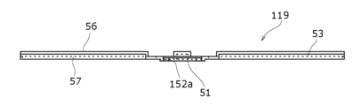
- FIG. 17 is a perspective view of the lower current collector plate 119 of the modification
- FIG. 18 is a plane view of the lower current collector plate 119 when viewed from the side opposite to the negative electrode core joint side in the thickness direction.
- FIG. 19 is an axial cross-sectional view of the lower collector plate 19.
- the lower collector plate 119 includes a flat plate portion 51 located in the center in the radial direction, and one or more through holes 152a located radially outward of the flat plate portion 51.
- the lower current collector plate 119 does not have the projecting portion 58 .
- the shape of the through hole 152 a of the lower collector plate 119 is slightly different from the shape of the through hole 52 a of the lower collector plate 19 .
- Other configurations of the lower collector plate 119 are the same as those of the lower collector plate 19 .
- the cylindrical battery 10 (see FIG. 1) provided with the lower current collector plate 19 (see FIGS. 5 to 7) was used as the cylindrical battery of Example 1.
- FIG. The inner diameter of the cylindrical portion 16a (see FIG. 1) of the outer can 16 of the cylindrical battery 10 was set to 44.86 [mm], and the diameter (stamped diameter) of the circular thin portion 71 was set to 32 [mm].
- the outer diameter of the electrode body 14 was set to 43.4 [mm], and the diameter of the hollow portion 14a of the electrode body 14 (hollow portion diameter) was set to 5 [mm]. Further, the outer diameter of the lower collector plate 19 was set to 43 [mm], and the width of the radially extending portion 53 of the lower collector plate 19 was set to 7 [mm].
- the diameter of the central projecting portion of the lower current collector plate 19 that contacts the bottom plate portion 68 is set to 6 mm
- the diameter of the welded portion of the lower current collector plate 19 that is welded to the bottom plate portion 68 is set to 4 mm. [mm].
- the width of the groove 57 of the radially extending portion 53 was set to 1.5 [mm].
- FIG. 20 is a schematic cross-sectional view of the axially lower end portion of the cylindrical battery 10
- FIG. 21 shows the cylindrical battery 10 in a state in which the easily breakable portion is broken and the safety valve 72 is blown out, viewed from the axially lower side. It is a plan view when viewed.
- the shaded area is the area of the opening 93 created by blowing off the safety valve 72 that is blocked by the lower current collector plate 19 .
- the area that could contribute to gas exhaust was measured. Gas can pass through the electrode assembly 14 .
- the cylindrical battery 10 of Example 1 differs from the cylindrical battery 10 of Example 1 only in that the lower collector plate 19 is replaced with the lower collector plate 119 of the modified example (see FIGS. 17 to 19).
- FIG. 22 is a schematic cross-sectional view of the axially lower end portion of the cylindrical battery 110
- FIG. 1 is a plan view when viewed from .
- the hatched area is the area of the opening 93 created by blowing off the safety valve 72 that is blocked by the lower collector plate 119 .
- the area that could contribute to gas exhaust was measured.
- the area of the electrode assembly 14 exposed to the opening 93 of the bottom plate portion 68 of the cylindrical battery 110 without being obstructed by the lower collector plate 119 was 408.8 [mm 2 ].
- FIG. 24 is a schematic cross-sectional view of the axially lower end portion of the cylindrical battery 210
- FIG. 25 shows the cylindrical battery 210 in a state where the easily breakable portion is broken and the safety valve 72 is blown off.
- 1 is a plan view when viewed from .
- the shaded area is the area of the opening 93 created by blowing off the safety valve 72 that is blocked by the lower collector plate 219 .
- the area was 408.8 [mm 2 ], which was only the area exposed to the opening 93 of the bottom plate portion 68 of the cylindrical battery 210 without being obstructed by the lower collector plate 219 in the electrode body 14 .
- a gas flow velocity of 20 [m/s] was generated in the path from the electrode assembly (the part where the electrode plate and separator are located) to the safety valve.
- the gas flow rate is 20 [m/s]
- the safety valve is reached through the hollow portion 14a and the through holes (exhaust holes) 52a and 152a.
- a gas flow velocity of 160 [m/s] was generated in the path. Therefore, when the exhaust capacity was compared by "flow velocity [m/s] ⁇ exhaust area [mm 2 ]", Table 1 was obtained.
- the through hole 52a is provided at a location overlapping the hollow portion 14a of the electrode body 14 in the axial direction. may be set to Moreover, although the through hole 52a is provided at a position overlapping the safety valve 72 in the axial direction, the through hole of the current collector plate may be provided at a position not overlapping the safety valve in the axial direction.
- the current collecting plate of the present disclosure (lower current collecting plate 19) is arranged axially lower than the electrode body 14, and a safety valve is provided at the bottom of the can. It may be arranged axially below the body 14 and the safety valve may be provided in the axially upper sealing body. Even in this case, the use of the current collector plate of the present disclosure allows the electrolyte to permeate smoothly.
- the current collector plate of the present disclosure may be arranged axially above the electrode assembly, or the current collector plate of the present disclosure may be arranged axially below the electrode assembly and at the same time as the electrode assembly. It may be arranged on the upper side in the axial direction.
- the current collector plate of the present disclosure When the current collector plate of the present disclosure is arranged on the side where the safety valve is provided with respect to the electrode body with respect to the axial direction, the high temperature gas can be smoothly guided to the safety valve through the through hole of the current collector plate when the safety valve operates, and the exhaust gas can be discharged. It is preferable because it can be performed efficiently.
- the current collector plate of the present disclosure When the current collector plate of the present disclosure is arranged above the electrode body in the axial direction, the axial upper end of the electrode body is configured by the core exposed portion of one electrode, and the core exposed portion is collected. Needless to say, it is connected to an electric plate.
Landscapes
- Chemical & Material Sciences (AREA)
- Chemical Kinetics & Catalysis (AREA)
- Electrochemistry (AREA)
- General Chemical & Material Sciences (AREA)
- Engineering & Computer Science (AREA)
- Manufacturing & Machinery (AREA)
- Materials Engineering (AREA)
- Connection Of Batteries Or Terminals (AREA)
- Gas Exhaust Devices For Batteries (AREA)
Priority Applications (4)
| Application Number | Priority Date | Filing Date | Title |
|---|---|---|---|
| CN202380017801.6A CN118575359A (zh) | 2022-01-28 | 2023-01-23 | 电池以及集电板 |
| EP23746892.1A EP4471971A4 (en) | 2022-01-28 | 2023-01-23 | BATTERY AND CURRENT COLLECTOR |
| JP2023576894A JPWO2023145680A1 (https=) | 2022-01-28 | 2023-01-23 | |
| US18/729,804 US20250158243A1 (en) | 2022-01-28 | 2023-01-23 | Battery and current collector |
Applications Claiming Priority (2)
| Application Number | Priority Date | Filing Date | Title |
|---|---|---|---|
| JP2022-011695 | 2022-01-28 | ||
| JP2022011695 | 2022-01-28 |
Publications (1)
| Publication Number | Publication Date |
|---|---|
| WO2023145680A1 true WO2023145680A1 (ja) | 2023-08-03 |
Family
ID=87472027
Family Applications (1)
| Application Number | Title | Priority Date | Filing Date |
|---|---|---|---|
| PCT/JP2023/001893 Ceased WO2023145680A1 (ja) | 2022-01-28 | 2023-01-23 | 電池及び集電板 |
Country Status (5)
| Country | Link |
|---|---|
| US (1) | US20250158243A1 (https=) |
| EP (1) | EP4471971A4 (https=) |
| JP (1) | JPWO2023145680A1 (https=) |
| CN (1) | CN118575359A (https=) |
| WO (1) | WO2023145680A1 (https=) |
Cited By (3)
| Publication number | Priority date | Publication date | Assignee | Title |
|---|---|---|---|---|
| JP2025033443A (ja) * | 2023-08-29 | 2025-03-13 | トヨタ自動車株式会社 | 蓄電セル |
| WO2025249412A1 (ja) * | 2024-05-31 | 2025-12-04 | パナソニックIpマネジメント株式会社 | 蓄電装置 |
| WO2026048248A1 (ja) * | 2024-08-30 | 2026-03-05 | パナソニックIpマネジメント株式会社 | 二次電池 |
Families Citing this family (1)
| Publication number | Priority date | Publication date | Assignee | Title |
|---|---|---|---|---|
| DE102024128504A1 (de) * | 2024-10-02 | 2026-04-02 | Bayerische Motoren Werke Aktiengesellschaft | Batteriezelle und kraftfahrzeug aufweisend die batteriezelle |
Citations (9)
| Publication number | Priority date | Publication date | Assignee | Title |
|---|---|---|---|---|
| JP2001210308A (ja) * | 2000-01-31 | 2001-08-03 | Uchihashi Estec Co Ltd | 電池の保護構造及び電池内蔵用保護素子 |
| JP2007335156A (ja) | 2006-06-13 | 2007-12-27 | Honda Motor Co Ltd | 蓄電素子 |
| JP2009277643A (ja) * | 2008-01-28 | 2009-11-26 | Panasonic Corp | 二次電池用集電端子板、二次電池および二次電池の製造方法 |
| JP2012185912A (ja) * | 2011-03-03 | 2012-09-27 | Hitachi Vehicle Energy Ltd | 円筒形二次電池 |
| WO2013024774A1 (ja) * | 2011-08-18 | 2013-02-21 | 日立ビークルエナジー株式会社 | 円筒形二次電池 |
| JP2014053071A (ja) * | 2010-12-29 | 2014-03-20 | Sanyo Electric Co Ltd | 円筒形電池及びその製造方法 |
| WO2015098866A1 (ja) * | 2013-12-26 | 2015-07-02 | 新神戸電機株式会社 | 蓄電デバイス |
| JP2018049680A (ja) * | 2015-01-30 | 2018-03-29 | 三洋電機株式会社 | 円筒形非水電解質二次電池 |
| KR20190136550A (ko) * | 2018-05-31 | 2019-12-10 | 주식회사 엘지화학 | 이차전지용 캡 조립체 및 이를 포함하는 이차전지 |
Family Cites Families (1)
| Publication number | Priority date | Publication date | Assignee | Title |
|---|---|---|---|---|
| KR101323036B1 (ko) * | 2009-05-25 | 2013-10-29 | 도요타지도샤가부시키가이샤 | 전지 팩, 그 전지 팩을 탑재한 차량 및 기기 |
-
2023
- 2023-01-23 JP JP2023576894A patent/JPWO2023145680A1/ja active Pending
- 2023-01-23 US US18/729,804 patent/US20250158243A1/en active Pending
- 2023-01-23 EP EP23746892.1A patent/EP4471971A4/en active Pending
- 2023-01-23 CN CN202380017801.6A patent/CN118575359A/zh active Pending
- 2023-01-23 WO PCT/JP2023/001893 patent/WO2023145680A1/ja not_active Ceased
Patent Citations (9)
| Publication number | Priority date | Publication date | Assignee | Title |
|---|---|---|---|---|
| JP2001210308A (ja) * | 2000-01-31 | 2001-08-03 | Uchihashi Estec Co Ltd | 電池の保護構造及び電池内蔵用保護素子 |
| JP2007335156A (ja) | 2006-06-13 | 2007-12-27 | Honda Motor Co Ltd | 蓄電素子 |
| JP2009277643A (ja) * | 2008-01-28 | 2009-11-26 | Panasonic Corp | 二次電池用集電端子板、二次電池および二次電池の製造方法 |
| JP2014053071A (ja) * | 2010-12-29 | 2014-03-20 | Sanyo Electric Co Ltd | 円筒形電池及びその製造方法 |
| JP2012185912A (ja) * | 2011-03-03 | 2012-09-27 | Hitachi Vehicle Energy Ltd | 円筒形二次電池 |
| WO2013024774A1 (ja) * | 2011-08-18 | 2013-02-21 | 日立ビークルエナジー株式会社 | 円筒形二次電池 |
| WO2015098866A1 (ja) * | 2013-12-26 | 2015-07-02 | 新神戸電機株式会社 | 蓄電デバイス |
| JP2018049680A (ja) * | 2015-01-30 | 2018-03-29 | 三洋電機株式会社 | 円筒形非水電解質二次電池 |
| KR20190136550A (ko) * | 2018-05-31 | 2019-12-10 | 주식회사 엘지화학 | 이차전지용 캡 조립체 및 이를 포함하는 이차전지 |
Non-Patent Citations (1)
| Title |
|---|
| See also references of EP4471971A4 |
Cited By (4)
| Publication number | Priority date | Publication date | Assignee | Title |
|---|---|---|---|---|
| JP2025033443A (ja) * | 2023-08-29 | 2025-03-13 | トヨタ自動車株式会社 | 蓄電セル |
| JP7827039B2 (ja) | 2023-08-29 | 2026-03-10 | トヨタ自動車株式会社 | 蓄電セル |
| WO2025249412A1 (ja) * | 2024-05-31 | 2025-12-04 | パナソニックIpマネジメント株式会社 | 蓄電装置 |
| WO2026048248A1 (ja) * | 2024-08-30 | 2026-03-05 | パナソニックIpマネジメント株式会社 | 二次電池 |
Also Published As
| Publication number | Publication date |
|---|---|
| EP4471971A1 (en) | 2024-12-04 |
| US20250158243A1 (en) | 2025-05-15 |
| JPWO2023145680A1 (https=) | 2023-08-03 |
| CN118575359A (zh) | 2024-08-30 |
| EP4471971A4 (en) | 2025-08-13 |
Similar Documents
| Publication | Publication Date | Title |
|---|---|---|
| WO2023145680A1 (ja) | 電池及び集電板 | |
| WO2018173899A1 (ja) | 非水電解質二次電池 | |
| WO2023281983A1 (ja) | 円筒形電池 | |
| JP7808586B2 (ja) | 円筒形電池、及びその製造方法 | |
| JP7808606B2 (ja) | 円筒形電池及び円筒形電池の製造方法 | |
| WO2024071239A1 (ja) | 蓄電装置 | |
| JP7738641B2 (ja) | 円筒形電池 | |
| EP4369509A1 (en) | Cylindrical battery | |
| WO2023002798A1 (ja) | 非水電解質二次電池及び非水電解質二次電池の製造方法 | |
| WO2022249989A1 (ja) | 非水電解質二次電池 | |
| WO2022181338A1 (ja) | 円筒形電池 | |
| US20250379338A1 (en) | Cylindrical battery | |
| WO2025047136A1 (ja) | 円筒形電池 | |
| WO2025182714A1 (ja) | 非水電解質二次電池 | |
| WO2025069835A1 (ja) | 円筒形電池 | |
| WO2026071149A1 (ja) | 非水電解質二次電池 | |
| WO2025248987A1 (ja) | 蓄電装置 | |
| WO2026070618A1 (ja) | 円筒形電池 | |
| WO2026048538A1 (ja) | 円筒形電池 | |
| WO2023189792A1 (ja) | 円筒形電池 | |
| WO2025095073A1 (ja) | 蓄電装置 | |
| WO2025249412A1 (ja) | 蓄電装置 | |
| WO2025070152A1 (ja) | 円筒形電池 | |
| WO2025182621A1 (ja) | 円筒形二次電池 | |
| WO2025164364A1 (ja) | 円筒形二次電池 |
Legal Events
| Date | Code | Title | Description |
|---|---|---|---|
| 121 | Ep: the epo has been informed by wipo that ep was designated in this application |
Ref document number: 23746892 Country of ref document: EP Kind code of ref document: A1 |
|
| ENP | Entry into the national phase |
Ref document number: 2023576894 Country of ref document: JP Kind code of ref document: A |
|
| WWE | Wipo information: entry into national phase |
Ref document number: 202447054094 Country of ref document: IN |
|
| WWE | Wipo information: entry into national phase |
Ref document number: 18729804 Country of ref document: US |
|
| WWE | Wipo information: entry into national phase |
Ref document number: 202380017801.6 Country of ref document: CN |
|
| NENP | Non-entry into the national phase |
Ref country code: DE |
|
| ENP | Entry into the national phase |
Ref document number: 2023746892 Country of ref document: EP Effective date: 20240828 |
|
| WWP | Wipo information: published in national office |
Ref document number: 18729804 Country of ref document: US |