WO2023145480A1 - Système d'imagerie médicale, procédé de commande et programme - Google Patents
Système d'imagerie médicale, procédé de commande et programme Download PDFInfo
- Publication number
- WO2023145480A1 WO2023145480A1 PCT/JP2023/000721 JP2023000721W WO2023145480A1 WO 2023145480 A1 WO2023145480 A1 WO 2023145480A1 JP 2023000721 W JP2023000721 W JP 2023000721W WO 2023145480 A1 WO2023145480 A1 WO 2023145480A1
- Authority
- WO
- WIPO (PCT)
- Prior art keywords
- focus lens
- medical imaging
- lens movement
- calculated
- evaluation
- Prior art date
Links
Images


Classifications
-
- A—HUMAN NECESSITIES
- A61—MEDICAL OR VETERINARY SCIENCE; HYGIENE
- A61B—DIAGNOSIS; SURGERY; IDENTIFICATION
- A61B1/00—Instruments for performing medical examinations of the interior of cavities or tubes of the body by visual or photographical inspection, e.g. endoscopes; Illuminating arrangements therefor
-
- G—PHYSICS
- G02—OPTICS
- G02B—OPTICAL ELEMENTS, SYSTEMS OR APPARATUS
- G02B7/00—Mountings, adjusting means, or light-tight connections, for optical elements
- G02B7/28—Systems for automatic generation of focusing signals
-
- G—PHYSICS
- G02—OPTICS
- G02B—OPTICAL ELEMENTS, SYSTEMS OR APPARATUS
- G02B7/00—Mountings, adjusting means, or light-tight connections, for optical elements
- G02B7/28—Systems for automatic generation of focusing signals
- G02B7/36—Systems for automatic generation of focusing signals using image sharpness techniques, e.g. image processing techniques for generating autofocus signals
-
- G—PHYSICS
- G03—PHOTOGRAPHY; CINEMATOGRAPHY; ANALOGOUS TECHNIQUES USING WAVES OTHER THAN OPTICAL WAVES; ELECTROGRAPHY; HOLOGRAPHY
- G03B—APPARATUS OR ARRANGEMENTS FOR TAKING PHOTOGRAPHS OR FOR PROJECTING OR VIEWING THEM; APPARATUS OR ARRANGEMENTS EMPLOYING ANALOGOUS TECHNIQUES USING WAVES OTHER THAN OPTICAL WAVES; ACCESSORIES THEREFOR
- G03B13/00—Viewfinders; Focusing aids for cameras; Means for focusing for cameras; Autofocus systems for cameras
- G03B13/32—Means for focusing
- G03B13/34—Power focusing
- G03B13/36—Autofocus systems
-
- G—PHYSICS
- G03—PHOTOGRAPHY; CINEMATOGRAPHY; ANALOGOUS TECHNIQUES USING WAVES OTHER THAN OPTICAL WAVES; ELECTROGRAPHY; HOLOGRAPHY
- G03B—APPARATUS OR ARRANGEMENTS FOR TAKING PHOTOGRAPHS OR FOR PROJECTING OR VIEWING THEM; APPARATUS OR ARRANGEMENTS EMPLOYING ANALOGOUS TECHNIQUES USING WAVES OTHER THAN OPTICAL WAVES; ACCESSORIES THEREFOR
- G03B15/00—Special procedures for taking photographs; Apparatus therefor
-
- H—ELECTRICITY
- H04—ELECTRIC COMMUNICATION TECHNIQUE
- H04N—PICTORIAL COMMUNICATION, e.g. TELEVISION
- H04N23/00—Cameras or camera modules comprising electronic image sensors; Control thereof
- H04N23/60—Control of cameras or camera modules
- H04N23/67—Focus control based on electronic image sensor signals
Definitions
- the present disclosure relates to a medical imaging system, a control method, and a program, and more particularly to a medical imaging system, a control method, and a program capable of coping with the case where there are multiple areas to be focused.
- Patent Document 1 discloses that a highly accurate AF function is realized by devising a wobbling operation in an observation mode in which lights with different wavelengths are alternately irradiated.
- the present disclosure has been made in view of this situation, and is intended to be able to deal with the case where there are multiple areas to focus on.
- a medical imaging system includes a medical imaging apparatus that has an assignable button to which execution of a selected function can be assigned and that images an operating field during surgery to generate a surgical video signal; a control device for controlling an apparatus, the control device having one or more processors and one or more storage devices storing a program, the processor executing the program to control the medical imaging device; Calculate a plurality of AF evaluation values based on the surgical video signal output from the above, calculate a focus lens movement position corresponding to each AF evaluation value based on the calculated plurality of AF evaluation values, In the medical imaging system, at least two of the calculated focus lens movement positions are set for assignable buttons.
- a control method is a control device that controls a medical imaging device that has an assignable button to which execution of a selected function can be assigned and that images a surgical field during surgery to generate a surgical video signal, A plurality of AF evaluation values are calculated based on the surgical image signal output from the medical imaging device, and focus lens movement positions corresponding to the respective AF evaluation values are determined based on the calculated plurality of AF evaluation values. and setting at least two of the calculated focus lens movement positions for the assignable button.
- a program is a computer output from a medical imaging device that has an assignable button to which execution of a selected function can be assigned and that images an operative field during surgery and generates a surgical video signal. Based on the surgical image signal, a plurality of AF evaluation values are calculated, based on the calculated plurality of AF evaluation values, a focus lens movement position corresponding to each AF evaluation value is calculated, and for the assignable button, The program functions as a control device that sets at least two of the calculated focus lens movement positions.
- a plurality of AF evaluation values are calculated based on a surgical video signal output from a medical imaging apparatus, and the calculated AF evaluation values are are calculated for each AF evaluation value, and at least two of the calculated focus lens movement positions are set for the assignable buttons of the medical imaging apparatus.
- the medical imaging device and the control device included in the medical imaging system may be independent devices, or may be internal blocks forming one device.
- FIG. 1 is a diagram illustrating a configuration example of a medical imaging system to which technology according to the present disclosure is applied;
- FIG. 3 is a block diagram showing a detailed configuration example of a camera head and a control device;
- FIG. It is a figure which shows the structural example of a control program. It is a perspective view which shows the structural example of a camera head.
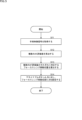
- FIG. 11 is a flowchart illustrating a first example of assignable button setting processing;
- FIG. 10 is a diagram showing a calculation example of an AF evaluation value;
- FIG. 11 is a flowchart illustrating a second example of assignable button setting processing;
- FIG. 10 is a diagram showing an example of AF evaluation frame settings;
- FIG. 10 is a flowchart for explaining an assignable button operation handling process
- FIG. FIG. 10 is a diagram showing another configuration example of a medical imaging system to which the technology according to the present disclosure is applied
- 1 is a diagram illustrating a configuration example of a microsurgery system to which technology according to the present disclosure is applied
- FIG. 1 is a block diagram showing a configuration example of an imaging system to which technology according to the present disclosure is applied
- FIG. It is a block diagram which shows the hardware constitutions of a control apparatus.
- FIG. 1 is a diagram showing a configuration example of a medical imaging system to which technology according to the present disclosure is applied.
- FIG. 1 illustrates an endoscopic surgical system used in abdominal endoscopic surgery as a medical imaging system. Endoscopic surgery is a surgery that has replaced conventional open surgery in the medical field.
- the medical imaging system 1 includes an insertion section 11, a light source device 12, a light guide 13, a camera head 14, a transmission cable 15, a display device 16, a transmission cable 17, a control device 18, and a transmission cable 19.
- the camera head 14 is an example of a medical imaging device to which technology according to the present disclosure is applied.
- the control device 18 is an example of a control device to which technology according to the present disclosure is applied.
- the insertion portion 11 is a member that has a rigid elongated shape as a whole and is inserted into the living body.
- the insertion portion 11 is provided with an optical system having one or a plurality of lenses and condensing a subject image. Note that the insertion portion 11 and the camera head 14 may be integrated.
- the light guide 13 has one end detachably connected to the light source device 12 and the other end detachably connected to the insertion portion 11 .
- the light source device 12 supplies light for illuminating the inside of the living body to one end of the light guide 13 under the control of the control device 18 .
- the light guide 13 transmits the light supplied from the light source device 12 from one end to the other end and supplies the light to the insertion section 11 .
- the light supplied to the insertion section 11 is emitted from the distal end of the insertion section 11 and irradiated into the living body.
- the light (object image) including the light irradiated into the living body and reflected inside the living body is condensed by the optical system in the insertion section 11 .
- a camera head 14 is detachably connected to an eyepiece portion 11 ⁇ /b>A, which is the proximal end of the insertion portion 11 .
- the subject image may include light emitted from a living body or a reagent absorbed by the living body, or light from a light source other than the light source device 12 .
- the camera head 14 captures the subject image condensed in the insertion section 11, and outputs a surgical video signal (for example, a RAW signal) obtained by the imaging.
- the surgical video signal is, for example, a video signal corresponding to video of 4K resolution (3840 pixels ⁇ 2160 pixels) or higher.
- a video (image frame thereof) based on a surgical video signal is also referred to as a surgical image.
- the transmission cable 15 transmits surgical video signals and the like output from the camera head 14 to the control device 18 . Also, the transmission cable 15 transmits control signals, synchronization signals, clock signals, power, etc. output from the control device 18 to the camera head 14 .
- the transmission of surgical video signals and the like from the camera head 14 to the control device 18 via the transmission cable 15 may be either an electrical signal or an optical signal. The same applies to transmission of control signals, synchronization signals, and clock signals from the control device 18 to the camera head 14 via the transmission cable 15 .
- the transmission cable 17 has one end detachably connected to the display device 16 and the other end detachably connected to the control device 18 .
- the transmission cable 17 transmits the surgical video signal processed by the control device 18 and the control signal output from the control device 18 to the display device 16 .
- the display device 16 displays a surgical image based on the surgical video signal output from the camera head 14 under the control of the control device 18 .
- the control device 18 is configured as, for example, a CCU (Camera Control Unit), and includes a processor such as a CPU (Central Processing Unit), an FPGA (Field Programmable Gate Array), a storage device, and the like.
- the control device 18 outputs control signals and the like to each device including the light source device 12, the camera head 14, and the display device 16, thereby comprehensively controlling the operation of each device. Further, the control device 18 processes surgical image signals and the like output from the camera head 14, and controls the operation of each device based on the processing results.
- the transmission cable 19 has one end detachably connected to the light source device 12 and the other end detachably connected to the control device 18 .
- the transmission cable 19 transmits control signals and the like from the control device 18 to the light source device 12 .
- the camera head 14 includes a lens unit 31 , a lens drive section 32 , an imaging section 33 and an operation section 34 .
- the lens unit 31 includes a plurality of lenses movable along the optical axis, and forms the subject image condensed by the insertion section 11 on the imaging surface of the imaging section 33 .
- the lens unit 31 has a focus lens 41 and a zoom lens 42 .
- the focus lens 41 is composed of one or more lenses, and adjusts the focus of the camera head 14 by moving along the optical axis.
- the zoom lens 42 is composed of one or more lenses, and adjusts the angle of view of the camera head 14 by moving along the optical axis.
- the lens unit 31 has a focus mechanism for moving the focus lens 41 along the optical axis and an optical zoom mechanism for moving the zoom lens 42 along the optical axis.
- the lens drive unit 32 has an actuator that operates the focus mechanism and the optical zoom mechanism described above, and a driver that drives the actuator.
- the lens driving section 32 adjusts the focus and angle of view of the lens unit 31 under the control of the control device 18 . Further, the lens driving section 32 has a position sensor such as a photointerrupter.
- the lens drive unit 32 detects the position of the focus lens 41 and the position of the zoom lens 42 and outputs detection signals corresponding to those positions to the control device 18 .
- the imaging unit 33 has a sensor chip in which an imaging device, a signal processing circuit, etc. are integrally formed.
- the imaging device is an image sensor such as a CCD (Charge Coupled Device) or CMOS (Complementary Metal Oxide Semiconductor), and receives the subject image that is focused by the insertion section 11 and formed by the lens unit 31 and converts it into an electrical signal. do.
- the signal processing circuit performs signal processing such as AD conversion on the electric signal (analog signal) from the imaging element.
- the imaging unit 33 captures an image of the inside of the body under the control of the control device 18, and outputs a surgical video signal (digital data) subjected to signal processing such as AD conversion.
- the signal processing circuit of the imaging unit 33 may not be formed integrally with the imaging device, but may be provided separately.
- the image pickup device has a number of pixels capable of outputting a video signal corresponding to a video of 4K resolution or higher.
- the operation unit 34 is configured as buttons or the like for performing operations related to various functions such as AF (Auto Focus) function and MF (Manual Focus) function.
- the operation unit 34 outputs an operation signal to the control device 18 according to the user's operation.
- Users include surgical staff (operators, etc.) who perform surgery on patients.
- the control device 18 includes a signal processing section 51 , a control section 52 , an input section 53 , an output section 54 and a storage section 55 . Note that the hardware configuration of the control device 18 will be described later with reference to FIG. 13 .
- the signal processing unit 51 can be configured by an FPGA, a processor such as a DSP (Digital Signal Processor), or the like.
- the signal processing unit 51 performs RAW processing such as optical black arithmetic processing and demosaic processing on the surgical video signal from the imaging unit 33, and converts it into an RGB signal.
- the signal processing unit 51 performs RGB processing such as white balance, RGB gamma correction, and YC conversion on the obtained RGB signals. Further, the signal processing unit 51 performs YC processing such as color difference correction and noise reduction on the obtained Y, Cb/Cr signals.
- the signal processing unit 51 supplies the surgical image signal after signal processing to the control unit 52 .
- the control unit 52 is composed of a processor such as a CPU. By outputting control signals, the control unit 52 controls the operation of each device including the light source device 12 , the camera head 14 , and the display device 16 , and also controls the operation of the entire control device 18 .
- the control unit 52 can implement various functions (AF function, etc.) by reading and executing the control program stored in the storage unit 55 . A configuration example of the control program will be described later with reference to FIG.
- the control unit 52 controls light emission of the light emitting unit 61 included in the light source device 12 .
- the light emitting unit 61 emits WLI (White Light Imaging) light (for example, visible light including light with a wavelength band of 360 nm to 760 nm) as light in a first wavelength band (first wavelength light), for example, in a surgical area to be a subject. ) and special light such as IR (Infrared) light as light in a second wavelength band (second wavelength light).
- the IR light here may include NIR (Near Infrared) light.
- IR light may be light with a wavelength band of 760 nm or more and 1000 ⁇ m or less.
- the control unit 52 generates a surgical video signal for display based on the surgical video signal processed by the signal processing unit 51 and outputs it to the display device 16 .
- the display device 16 has a display using liquid crystal or organic EL (Electro Luminescence) or the like, and displays a surgical image based on a surgical video signal output from the control device 18 .
- the input unit 53 has operation devices such as buttons, switches, mice, keyboards, and touch panels, and receives user operations.
- the input unit 53 supplies the control unit 52 with an operation signal according to the user's operation.
- the output unit 54 has a speaker, a printer, etc., and outputs various information.
- the storage unit 55 is a storage device such as a semiconductor storage device or HDD (Hard Disk Drive).
- the storage unit 55 stores programs such as a control program executed by the control unit 52, information (data, parameters, etc.) necessary for processing of the control unit 52, and the like.
- FIG. 3 is a diagram showing a configuration example of the control program 81. As shown in FIG.
- the control program 81 is stored in the storage unit 55 and read and executed by the control unit 52 including a processor such as a CPU.
- the control program 81 may be executed by the signal processing section 51 .
- the control program 81 includes a focus control section 91 , an AF evaluation value calculation section 92 , a focus lens movement position calculation section 93 and an assignable button setting section 94 .
- the focus control unit 91 operates the lens driving unit 32 to adjust the focus of the lens unit 31 (change the position of the focus lens 41). For example, the focus control section 91 controls the AF operation of the focus lens 41 based on the position of the focus lens 41 detected by the lens drive section 32 and the AF evaluation value from the AF evaluation value calculation section 92 . The focus control section 91 also controls the AF operation of the focus lens 41 based on an operation signal from the operation section 34 or the input section 53 .
- the AF evaluation value calculation unit 92 calculates a plurality of AF evaluation values based on the surgical video signal from the camera head 14.
- the AF evaluation value is a focus evaluation value for evaluating the focus state of the surgical image (subject image inside) obtained from the surgical video signal.
- the AF evaluation value calculation unit 92 calculates the contrast and frequency components of the image based on the pixel information (for example, luminance data (Y) and Cb/Cr data) in one frame of the surgical image captured by the imaging unit 33. To detect.
- the AF evaluation value calculator 92 calculates an AF evaluation value based on the detected contrast and frequency components.
- the AF evaluation value calculation unit 92 may detect the contrast and frequency components of the image in the designated area based on the pixel information for each pixel in the designated area (for example, the AF evaluation frame) within the surgical image of one frame. I do not care.
- the focus lens movement position calculator 93 calculates the movement position of the focus lens 41 (focus lens movement position) corresponding to each AF evaluation value based on a plurality of AF evaluation values. It can be said that the focus lens movement position calculated in this way is the focus lens position corresponding to the in-focus position.
- the assignable button setting unit 94 sets at least two focus lens movement positions calculated based on a plurality of AF evaluation values for the assignable button.
- the assignable button is a button to which execution of a selected function can be assigned.
- FIG. 4 is a perspective view showing a configuration example of the camera head 14. As shown in FIG.
- the camera head 14 has a main body part 101 having a cylindrical shape, a cover part 102 and a connector part 103 fixed by closing an opening formed in the main body part 101 .
- An operation unit 34 for outputting an operation signal to the main unit 101 according to an operation by a user (surgical staff) is fixed on the upper surface of the main unit 101 .
- the main body 101 is made of metal (titanium, stainless steel, etc.) or metal (titanium, stainless steel, etc.), taking into consideration ease of gripping by the human hand, such as a shape having a curved surface that fits the shape of the hand when the user grips the camera head 14. It has a cylindrical shape using a material such as an alloy.
- a lens unit 31 , a lens driving section 32 and an imaging section 33 are provided inside the body section 101 .
- the cover part 102 is fixed to the main body part 101 by closing the opening on the side to which the insertion part 11 is connected among the openings formed in the main body part 101 .
- the connector part 103 is fixed to the main body part 101 by closing the opening on the side to which the transmission cable 15 is connected among the openings formed in the main body part 101 .
- the operation unit 34 has buttons 111-1 to 111-6 that accept input of operation signals by pressing from the outside. Six buttons 111-1 to 111-6 output different operation signals. Operation signals include, for example, a signal instructing AF to a predetermined position in the screen, a signal instructing movement of the optical system to the near (short distance) side and the far (far) side in MF, and a user's arbitrary signal. signals to be set to
- buttons 111-1 to 111-6 can be used as an assignable button that can be assigned to execute the selected function.
- the assignable button A is the button 111-5 and the assignable button B is the button 111-6.
- the assignable buttons A and B may be a combination of the buttons 111-1 and 111-2 instead of the combination of the buttons 111-5 and 111-6.
- step S ⁇ b>11 the control device 18 acquires the surgical image signal output from the camera head 14 .
- the control unit 52 or the like executes the control program 81 to process the surgical image signal from the camera head 14, thereby executing the processing of steps S12 to S14.
- the AF evaluation value calculation unit 92 calculates a plurality of AF evaluation values based on the surgical video signal.
- Methods for calculating the AF evaluation value include, for example, contrast AF.
- Contrast AF is a method of determining an AF evaluation value based on the contrast of a surgical image obtained from a surgical video signal, and adjusting the position of the focus lens 41 based on the AF evaluation value. Contrast can also be said to be a parameter obtained from surgical images.
- the AF evaluation value calculation unit 92 may use another AF evaluation value calculation method instead of contrast AF.
- the AF evaluation value calculation unit 92 calculates a plurality of AF evaluation values by moving the focus lens from the near side (Near Max) to the far side (Far Max), or based on a surgical video signal.
- Phase-difference AF that uses phase difference
- phase-difference AF that uses the signal of the image-plane phase-difference pixel included in the image sensor
- range-finding AF that uses a range-finding sensor for the ToF (Time of Flight) sensor, etc.
- the AF evaluation value may be calculated using a technique such as spectral AF that obtains the AF evaluation value for each wavelength.
- the AF evaluation value calculation unit 92 may combine a plurality of AF evaluation value calculation methods.
- the configuration of the camera head 14 may be changed according to the calculation method of the AF evaluation value.
- the camera head 14 when using phase difference AF, the camera head 14 preferably includes a phase difference optical system.
- the camera head 14 when using image plane phase difference AF, the camera head 14 preferably includes an imaging element including image plane phase difference pixels.
- the camera head 14 when using ranging AF, the camera head 14 preferably includes a ranging sensor.
- spectral AF is used, the camera head 14 preferably includes a spectroscopic optical system.
- the camera head 14 may output information necessary for calculating the AF evaluation value as the surgical video signal according to the AF evaluation value calculation method used. For example, when image plane phase difference AF is used, the camera head 14 can output a signal including a RAW signal and a phase difference signal as a surgical video signal. For example, when ranging AF is used, the camera head 14 can output a signal including a RAW signal and a ranging sensor signal as a surgical video signal.
- the AF evaluation value calculation unit 92 calculates a plurality of AF evaluation values based on the surgical video signal output from the camera head 14 according to the AF evaluation value calculation method used.
- the contrast AF method an AF evaluation value is calculated based on the contrast of the surgical image, and the position of the focus lens 41 is adjusted so that the AF evaluation value becomes the highest or a predetermined condition is satisfied.
- the contrast AF method may include a wobbling motion and a hill-climbing motion.
- the wobbling operation is an operation for slightly oscillating the focus lens 41 and estimating the direction of the contrast peak (the direction in which the focus lens 41 is moved on the optical axis) from the difference in the AF evaluation value when the oscillation is oscillated.
- the hill-climbing operation is an operation of searching for a contrast peak position based on a change in contrast when the focus lens 41 is moved.
- a plurality of AF evaluation values can be calculated by combining the wobbling motion and the hill-climbing motion.
- FIG. 6 is a diagram showing an example of AF evaluation value calculation.
- the horizontal axis represents the focus lens position (the left side in the figure is the Near side and the right side is the Far side), and the vertical axis represents the contrast.
- contrast AF the search for the in-focus position is started from the start position after the wobbling operation, and the AF evaluation value based on the contrast is calculated while moving the focus lens 41 in the direction of increasing the contrast. At this time, the in-focus position is where the contrast peaks (contrast maximum values).
- Two AF evaluation values based on are calculated.
- step S13 the focus lens movement position calculator 93 calculates the focus lens movement position corresponding to each of the calculated plurality of AF evaluation values.
- the focus lens movement position calculator 93 calculates the focus lens movement position corresponding to each of the calculated plurality of AF evaluation values.
- two focus lens movement positions A and B corresponding to two AF evaluation values based on peak A and peak B are calculated.
- step S14 the assignable button setting unit 94 sets the calculated focus lens movement positions A and B for the assignable buttons A and B.
- Setting information relating to assignable button settings can be stored in the storage unit 55 .
- an assignable button A (button 111-5 in FIG. 4) is set with a command to move the focus lens to a focus lens movement position A corresponding to an AF evaluation value based on peak A (near side peak).
- a move command to the focus lens movement position B corresponding to the AF evaluation value based on B (far-side peak) is set to the assignable button B (button 111-6 in FIG. 4).
- the operation unit 34 of the camera head 14 may be provided with one or more assignable buttons. can be done. If the camera head 14 has one assignable button, the assignable button setting unit 94 sets at least two focus lens movement positions for the assignable button. Also, when the camera head 14 has a plurality of assignable buttons, the assignable button setting section 94 sets at least one focus lens movement position for each of the assignable buttons.
- a toggle button or the like as an assignable button, it is possible to set a movement command to two focus lens movement positions A and B for one assignable button A.
- the assignable button A when the assignable button A is pressed first, the focus lens 41 is moved to the focus lens movement position A, and when the assignable button A is pressed next, the focus lens 41 is moved to the focus position. It is sufficient to perform control so as to move to the lens movement position B. In the same way, the movement to the focus lens movement position A and the focus lens movement position B can be alternately repeated for the subsequent operation of the assignable button A.
- the number of calculated AF evaluation values may be two or more.
- the number of calculated AF evaluation values may be two or more.
- three AF evaluation values are calculated based on peak A, peak B, and peak C
- Buttons can be set.
- three assignable buttons corresponding to three focus lens movement positions A, B, and C may be prepared, or three focus lens movement positions A, B, and C may be prepared for two or less assignable buttons. You may set a move command to .
- one assignable button A is assigned to the focus lens movement positions A, B, and C.
- a move command to B and C can be set.
- the focus lens 41 moves to the focus lens movement position A when the assignable button A is pressed once, and moves to the focus lens movement position B when the assignable button A is pressed twice.
- the assignable button A is pressed three times, it moves to the focus lens movement position C and moves from the near side to the far side.
- the assignable button A is pressed four times, the focus lens 41 returns to the focus lens movement position A.
- the focus lens position is switched in order according to the number of times the assignable button is pressed.
- the focus lens movement positions A, B, and C are calculated from the near side to the far side by using a pair of buttons such as an upper button and a lower button as the two assignable buttons A and B.
- the focus lens 41 may move to the near side when the upper button is pressed, and may move to the far side when the lower button is pressed.
- the focus lens 41 moves from the focus lens movement position C to the focus lens movement positions B and A in that order. It will move to the near side.
- the lower button is pressed twice when the focus lens 41 is at focus lens movement position A, the focus lens 41 moves from focus lens movement position A to focus lens movement positions B and C in this order toward the far side. will move.
- a near-priority mode gives priority to the near-side focus lens movement position
- a far-priority mode prioritizes the far-side focus lens movement position.
- the near priority mode when the near priority mode is selected, it is essential to set a movement command to the most near side (Near Max) focus lens movement position among the calculated focus lens movement positions to the assignable button, The focus lens movement position closest to the near side can be set as the default focus lens position.
- the far priority mode when the far priority mode is selected, it is essential to set a movement command to the focus lens movement position closest to the far side (Far Max) among the calculated focus lens movement positions to the assignable button.
- the focus lens movement position closest to the far side can be set as the default focus lens position.
- a focus lens movement position that is automatically set according to a predetermined rule, such as setting the movement position preferentially for an assignable button, may be selected.
- the user may manually select the focus lens movement position (AF evaluation value) to be set for the assignable button from among the calculated focus lens movement positions (AF evaluation value).
- AF evaluation value focus lens movement position
- a movement position may be automatically set to an assignable button.
- the assignable button may be a combination of the buttons 111-5 and 111-6 in FIG. 4, a toggle button, a combination of the upper button and the lower button, or other operating means such as a rotating ring.
- the rotary ring has a rotary operation member rotatably held about a rotary shaft, and by rotating the rotary operation member through a predetermined rotation angle, the focus lens movement position can be switched.
- any operation means may be used as long as it can assign a movement command to two or more focus lens movement positions, and any operation means may be used.
- the focus lens can be moved with respect to the assignable button based on the stored presets.
- the position may be set automatically.
- the focus lens movement position can be automatically set for the assignable button.
- the focus lens By inputting surgical images obtained from surgical video signals into a trained model trained by machine learning, when a tumor is found, the focus lens focuses on the area of interest, with the location of the tumor as the area of interest.
- a move command to a move position can be set for an assignable button.
- the default focus lens position may be the focus lens movement position for focusing on the region of interest.
- the trained model can use a DNN (Deep Neural Network) trained with images as learning data as input and tumor-related information as output.
- DNN Deep Neural Network
- each of the plurality of tumors is set as a region of interest, and a movement command to a focus lens movement position that focuses on the region of interest is set to an assignable button.
- the focused attention area may be switched according to the number of times the assignable button is pressed.
- assignable button setting processing has been described above.
- assignable button setting process multiple AF evaluation values are calculated based on the surgical image signal, the focus lens movement position corresponding to each AF evaluation value is calculated based on the multiple AF evaluation values, and the assignable button is focused. At least two of the lens movement positions are set. As a result, the focus lens 41 can be moved to at least two focus lens movement positions according to the operation of the assignable button, so that it is possible to cope with the case where there are a plurality of areas to be focused.
- the surgical staff performs the surgery while alternately looking at the plurality of regions that are the points of interest.
- the surgical staff selects the parts to be removed and the parts that should not be removed (gallbladder, etc.). Surgery is performed while looking alternately, and these points can be points of interest.
- the AF evaluation value is calculated by inputting the pixel signal values included in one AF evaluation frame set virtually on the surgical image into the AF evaluation formula, and the calculated AF The focus lens movement position corresponding to the evaluation value is read, and the focus lens is moved based on the read movement position. As a result, the operation of focusing (focusing operation) on an area that the surgical staff wants to focus on (focus on and see) has been performed.
- a plurality of AF evaluation values are calculated, and at least two focus lens movement positions corresponding to each AF evaluation value are assigned to an assignable button so that the area desired to be focused is It is also possible to deal with multiple cases.
- the surgical staff it is possible for the surgical staff to easily switch the focus position simply by operating an assignable button at the discretion of the surgical staff, so that the surgical staff can view the surgical images without stress.
- step S31 the control device 18 acquires a surgical video signal (for example, a RAW signal) output from the camera head 14.
- the control device 18 processes the surgical video signal from the camera head 14, thereby executing the processes of steps S32 to S36.
- the AF evaluation value calculation unit 92 uses the surgical video signal from the camera head 14 to generate a luminance image (Y image).
- a luminance image is generated by performing demosaic processing on a RAW signal acquired as a surgical video signal, or the R signal, G signal, and B signal included in the RAW signal are
- a brightness image can be generated by executing brightness image generation processing after adjusting the values by assigning weights to each of them.
- the AF evaluation value calculation unit 92 sets a plurality of virtual AF evaluation frames on the luminance image, and calculates the AF evaluation value of each AF evaluation frame. For example, the AF evaluation value of the center frame, which is the AF evaluation frame set in the center of the luminance image, and the AF evaluation value of the peripheral frame, which is the AF evaluation frame set around the center, are calculated.
- FIG. 8 is a diagram showing a setting example of the AF evaluation frame.
- three AF evaluation frames 152 a to 152 c are set on the luminance image 151 .
- the AF evaluation frame 152a is a central frame set in the central portion of the luminance image 151
- the AF evaluation frames 152b and 152c are peripheral frames set to the left and right of the central portion.
- An AF evaluation value is calculated for each of 152a to 152c.
- Methods for calculating AF evaluation values include, for example, the average and variance of luminance values within the AF evaluation frame, the maximum and minimum values of luminance values in the vertical direction, and the maximum and minimum values of luminance values in the horizontal direction. It can be calculated using various parameters obtained from (luminance image, etc.).
- step S34 the focus control unit 91 operates the lens driving unit 32 to move the focus lens 41 to the focus lens position corresponding to the maximum contrast value of the central frame.
- the AF evaluation value for the center frame is calculated, and the maximum contrast value in the center frame can be focused on. That is, the default focus lens position is the focus lens position corresponding to the maximum contrast value of the center frame.
- the AF evaluation value calculation unit 92 always calculates the AF evaluation value for the peripheral frame as well, so that the maximum contrast value for the peripheral frame is calculated.
- step S35 the focus lens movement position calculator 93 calculates a focus lens movement position A corresponding to the maximum contrast value of the central frame and a focus lens movement position B corresponding to the maximum contrast value of the peripheral frame.
- step S36 the assignable button setting unit 94 sets a move command to the focus lens movement position A corresponding to the maximum contrast value of the central frame for the assignable button A (for example, the button 111-5 in FIG. 4), A move command to the focus lens movement position B corresponding to the maximum contrast value of the peripheral frame is set for the assignable button B (eg, button 111-6 in FIG. 4).
- Setting information relating to assignable button settings can be stored in the storage unit 55 .
- the number of assignable buttons is not limited to two, and the number of focus lens movement positions calculated based on a plurality of AF evaluation values is Although it is not limited to two, the description thereof will be omitted to avoid repetition. Also in the second example, in addition to the buttons 111-5 and 111-6 in FIG. It is optional to use the operating means.
- assignable button setting processing has been described above.
- assignable button setting process multiple AF evaluation frames are set on the surgical image, the AF evaluation values for each of the multiple AF evaluation frames are calculated, and the maximum contrast value for each AF evaluation frame is calculated based on the AF evaluation values. are calculated, and at least two of the focus lens movement positions are set to the assignable buttons.
- the focus lens 41 can be moved to at least two focus lens movement positions according to the operation of the assignable button, so that it is possible to cope with the case where there are a plurality of areas to be focused.
- step S51 the control unit 52 determines whether or not the assignable button A has been pressed based on the operation signal from the operation unit 34 of the camera head 14.
- step S51 If it is determined in step S51 that assignable button A has been pressed, the process proceeds to step S52.
- the focus control unit 91 operates the lens driving unit 32 based on the setting information stored in the storage unit 55 to move the focus lens 41 to the focus lens movement position A set to the assignable button A. to move.
- step S51 determines whether or not the assignable button A has been pressed.
- step S53 the control unit 52 determines whether or not the assignable button B has been pressed based on the operation signal from the operation unit 34 of the camera head 14.
- step S53 If it is determined in step S53 that the assignable button B has been pressed, the process proceeds to step S54.
- step S ⁇ b>54 the focus control unit 91 operates the lens driving unit 32 based on the setting information stored in the storage unit 55 to move the focus lens 41 to the focus lens movement position B set to the assignable button B. to move.
- step S52 or S54 ends, or if it is determined in the determination process of step S53 that the assignable button B has not been pressed, the series of processes ends.
- the focus lens 41 can be moved to at least two focus lens movement positions according to the operation of the assignable button by the surgical staff. be able to.
- the surgical staff can operate assignable buttons to perform surgery while alternately viewing a plurality of areas (for example, areas to be resected and areas not to be resected).
- FIG. 10 illustrates an endoscopic surgical system including a flexible endoscope as a medical imaging system.
- the medical imaging system 2 includes an insertion section 201 having a flexible (bendable) portion inserted into the living body, and a camera head 202 that captures a subject image condensed in the insertion section 201 and outputs a surgical video signal.
- a fiberscope or the like can be used that guides light (object image) captured by an optical system at the tip to an eyepiece portion outside the body for observation.
- the camera head 202 is provided with assignable buttons A and B similarly to the camera head 14 shown in FIG.
- the medical imaging system 2 further includes a light source device 12, a display device 16, and a control device 18.
- the light source device 12 supplies light for illuminating the inside of the living body to the connecting portion 203 under the control of the control device 18 .
- the control device 18 receives and processes the surgical image signal output from the camera head 202 via the connection unit 203, and operates the light source device 12, the display device 16, and the camera head 202 based on the processing result. comprehensively control the
- the controller 18 can execute the assignable button setting process of FIG. 5 or 7 based on the surgical video signal from the camera head 202.
- the control device 18 can execute the assignable button operation processing shown in FIG. 9 based on the operation signal from the camera head 202 .
- the medical imaging system 2 configured as described above, when there are a plurality of areas to be focused on when performing endoscopic surgery using an endoscopic surgical system including a flexible endoscope, these areas are The focus lens movement position corresponding to each AF evaluation value can be set to the assignable button. Therefore, by operating the assignable button, the surgical staff can focus on any one of the multiple areas to be focused, and perform surgery while alternately viewing multiple areas.
- FIG. 11 illustrates a microsurgery system using a surgical video microscope device 210 as an observation medical device for observing the inside of a patient's body.
- FIG. 11 shows a doctor 220 performing surgery on a patient 240 on an operating table 230 using surgical instruments 221 such as a scalpel, forceps, and forceps.
- surgical instruments 221 such as a scalpel, forceps, and forceps.
- a state of surgery is shown as an example of the surgical procedure, but the surgical procedure using the surgical video microscope device 210 is not limited to surgery, and various other surgical procedures (medical treatments such as examinations, etc.) ).
- a surgical video microscope device 210 is provided beside the operating table 230 .
- the surgical video microscope apparatus 210 has a base portion 211 as a base, an arm portion 212 extending from the base portion 211, and an imaging unit 215 connected to the tip of the arm portion 212 as a tip unit.
- the arm portion 212 has joint portions 213a, 213b, and 213c, and links 214a and 214b connected by the joint portions 213a to 213c. drive is controlled.
- the imaging unit 215 is a unit that acquires an image of an imaging target by including an optical system that acquires an optical image of a subject, and is configured as a camera capable of imaging moving images and still images, for example.
- the posture and orientation of the arm section 212 and the imaging unit 215 are controlled by the surgical video microscope apparatus 210 so that the image pickup unit 215 provided at the tip of the arm section 212 picks up an image of the treatment site of the patient 240 . position is controlled.
- the configuration of the imaging unit 215 connected as a tip unit to the tip of the arm section 212 is not particularly limited, and may be configured as an endoscope or a microscope, for example.
- a display device 250 having a display is installed at a position facing the doctor 220 .
- a surgical image acquired by the imaging unit 215 is displayed on the display device 250 after being subjected to various signal processing by, for example, a signal processing device built in or external to the surgical video microscope device 210 . Thereby, the doctor 220 can perform surgery while viewing the surgical image displayed on the display device 250 .
- the imaging unit 215 includes, for example, the camera head 14 and the light source device 12 (light emitting section 61) shown in FIG.
- assignable buttons A and B can be provided on the housing surface of the imaging unit 215 .
- the assignable buttons A and B may be provided on a surface other than the housing surface of the imaging unit 215 .
- the display device 250 corresponds to the display device 16 in FIG.
- a signal processing device that performs various signal processing on the surgical image acquired by the imaging unit 215 corresponds to the control device 18 in FIG.
- the signal processing device can execute the assignable button setting process of FIG. 5 or 7 based on the surgical image signal from the imaging unit 215 .
- the control device 18 can execute the assignable button operation corresponding process of FIG. 9 based on the operation signal from the imaging unit 215 .
- the surgical staff such as the doctor 220 can focus on any one of the plurality of regions to be focused by operating the assignable buttons, and perform medical treatment such as surgery while alternately viewing the plurality of regions. corrective action can be taken.
- FIG. 12 shows a configuration example of an imaging device, which is an example of a general imaging system.
- an imaging device 310 is configured as, for example, a consumer camera.
- the imaging device 310 includes a lens unit 331, a lens driving unit 332, an imaging unit 333, an operation unit 334, a signal processing unit 351, a control unit 352, an input unit 353, an output unit 354, a storage unit 355, a light emitting unit 356, and a display unit. 357.
- the lens unit 331, the lens driving section 332, the imaging section 333, and the operating section 334 correspond to the lens unit 31, the lens driving section 32, the imaging section 33, and the operating section 34 included in the camera head 14 in FIG.
- a focus lens 341 and a zoom lens 342 included in the lens unit 331 also correspond to the focus lens 41 and the zoom lens 42 included in the lens unit 31 in FIG. 2, respectively.
- the operation unit 334 is fixed to the housing surface of the imaging device 310 and has assignable buttons A and B, like the operation unit 34 of the camera head 14 shown in FIG.
- a signal processing unit 351, a control unit 352, an input unit 353, an output unit 354, and a storage unit 355 are provided in the control device 18 of FIG. 55, respectively.
- the light emitting portion 356 corresponds to the light emitting portion 61 included in the light source device 12 in FIG.
- a display unit 357 corresponds to the display device 16 in FIG.
- the signal processing unit 351 or the control unit 352 can execute the assignable button setting process of FIG. 5 or 7 based on the video signal from the imaging unit 333.
- the control unit 352 can execute the assignable button operation processing shown in FIG. 9 based on the operation signal from the operation unit 334 .
- the focus lens movement position corresponding to the AF evaluation value of each of these areas can be set using the assignable buttons. can be set to Therefore, by operating the assignable button, the photographer can focus on any one of the plurality of areas to be focused, and can perform shooting while alternately looking at the plurality of areas.
- FIG. 13 is a block diagram showing the hardware configuration of the control device 18 that constitutes the medical imaging system 1 of FIG.
- the control device 18 includes a CPU 501, a ROM (Read Only Memory) 503, and a RAM (Random Access Memory) 505, which are connected via a host bus 507.
- the control device 18 also includes an input device 515 , an output device 517 , a storage device 519 , drives 521 , a connection port 523 and a communication device 525 and is connected to the interface 513 .
- Host bus 507 is connected to interface 513 via bridge 509 and external bus 511 .
- the CPU 501 functions as an arithmetic processing device and a control device, and controls all or part of the operations within the control device 18 according to various programs recorded in the ROM 503, RAM 505, storage device 519, or removable recording medium 527.
- the CPU 501 reads out and executes the control program 81 (FIG. 3) stored in the storage device 519 to control the focus control unit 91, the AF evaluation value calculation unit 92, the focus lens movement position calculation unit 93, and the assignable button.
- the function of the setting unit 94 can be realized.
- the input device 515 is an operation unit operated by the user, such as a mouse, keyboard, touch panel, button, switch, lever, and pedal. Also, the input device 515 may be, for example, a remote controller, or may be an external connection device 529 such as a portable device corresponding to the operation of the control device 18 . By operating the input device 515, the user can input various data to the control device 18 and instruct processing operations.
- the output device 517 is configured by a device capable of visually or audibly notifying the user of the acquired information.
- the output device 517 is configured as a display device having a display using liquid crystal, organic EL, or the like, a lamp, an audio output device such as a speaker or headphones, a printer device, or the like.
- the output device 517 outputs, for example, results obtained by various processes performed by the control device 18 .
- the light source device 12 or the display device 16 in FIG. 2 may be implemented by the output device 517 .
- the storage device 519 is a data storage device configured as an example of the storage unit 55 of the control device 18 .
- the storage device 519 is composed of, for example, a magnetic storage device such as an HDD, a semiconductor storage device, an optical storage device, or a magneto-optical storage device.
- the storage device 519 stores programs executed by the CPU 501 (for example, the control program 81 in FIG. 3), various data, and the like.
- the drive 521 is a recording medium reader/writer and is either built into the control device 18 or externally attached.
- the drive 521 reads information recorded on a removable recording medium 527 such as an optical disk, semiconductor memory, magnetic disk, magneto-optical disk, or the like, and outputs the information to the RAM 505 .
- the drive 521 can also write information to the attached removable recording medium 527 .
- the connection port 523 is a port for directly connecting the external connection device 529 to the control device 18 .
- the connection port 523 includes, for example, a USB (Universal Serial Bus) port, HDMI (registered trademark) (High-Definition Multimedia Interface) port, IEEE1394 port, SCSI (Small Computer System Interface), and the like.
- USB Universal Serial Bus
- HDMI registered trademark
- SCSI Small Computer System Interface
- the communication device 525 is, for example, a communication interface configured with a communication device or the like for connecting to a communication network (network) 531 .
- the communication device 525 is, for example, wired or wireless LAN (Local Area Network) communication, cellular communication (e.g., 5G (5th Generation)), short-range wireless communication such as Bluetooth (registered trademark), or WUSB (Wireless USB). It is a communication module etc. corresponding to wireless communication etc.
- the communication device 525 may be a router for optical communication, a modem for various types of communication, or the like.
- the communication device 525 can, for example, transmit and receive signals to and from the Internet or other communication devices according to a predetermined protocol such as TCP/IP.
- the communication network 531 connected to the communication device 525 may be configured by a wired or wireless network or the like.
- the communication network 531 may be, for example, the Internet, a home LAN, a mobile communication network, or a communication network in which infrared communication, radio wave communication, or satellite communication is performed.
- Each component of the control device 18 described above may be configured using general-purpose hardware, or may be configured with hardware specialized for the function of each component. That is, it is possible to appropriately change the hardware configuration to be used according to the technical level at which the technology according to the present disclosure is implemented.
- ⁇ Modification> In the second example of the assignable button setting process described above, a case was shown where a plurality of AF evaluation frames are set on the surgical image and the AF evaluation values for each of the multiple AF evaluation frames are calculated. Marking areas visually marked with biomarkers may be extracted as AF target areas, AF evaluation frames including those marking areas may be set, and AF evaluation values for each AF evaluation frame may be calculated.
- the focus lens movement position is calculated for each AF evaluation frame including the marking area, and at least two of the calculated focus lens movement positions are set to the assignable button.
- the R signal, G signal, and B signal of the surgical video signal RAW signal
- the marking area in the R signal and the marking area in the B signal correspond to different reagent areas. good too.
- the WLI image which is a surgical image obtained by irradiating the light emitting unit 61 of the light source device 12 with WLI light (first wavelength light)
- WLI light first wavelength light
- the light emitting unit 61 emits IR light.
- a plurality of AF evaluation values may be calculated by calculating an AF evaluation value for a specific marking area using an IR image that is a surgical image obtained by irradiating (second wavelength light).
- each of the AF evaluation values (a plurality of AF evaluation value) is calculated, and based on the calculated AF evaluation value, the focus lens movement positions corresponding to the first area and the second area are calculated, and at least two of the calculated focus lens movement positions are assigned to the assignable buttons. set.
- the evaluation value may be calculated by changing the wavelength of the light to be irradiated.
- AF target areas a plurality of attention areas may be extracted using a learned model learned by machine learning, and an AF evaluation value may be calculated for each of the extracted attention areas.
- the calculation method may be switched according to the surgical mode and observation mode.
- the setting position of the AF evaluation frame described above the setting position may be switched according to the surgical mode and the observation mode. That is, the AF parameters such as the calculation method of the AF evaluation value and the setting position of the AF evaluation frame can be switched according to the mode such as the surgical mode and the observation mode. Further, the AF characteristics (AF speed, various thresholds, etc.) may be changed based on any of the relationship between the surgical mode, observation mode, and AF target area (area, arrangement, etc.).
- the priority of the AF target area may be set based on the relationship (area, arrangement, etc.) of the AF target area.
- the assignment of the AF target areas may be automatically set based on the relationship of the AF target areas. For example, if one organ is dyed in two colors due to a biomarker or the like, which of the two colors is to be used as the default, or whether to set the focus lens movement position to the assignable button A, etc., are automatically set.
- each step described in the flowchart above can be executed by a single device, or can be shared by a plurality of devices.
- the plurality of processes included in the one step can be executed by one device or shared by a plurality of devices.
- a system means a set of multiple components (devices, modules (parts), etc.), and it does not matter whether all the components are in the same housing. Therefore, both a plurality of devices housed in separate enclosures and connected via a network and a single device housing a plurality of modules within a single enclosure are systems.
- the present disclosure can be configured as follows.
- a medical imaging device having an assignable button to which execution of a selected function can be assigned, imaging an operating field during surgery and generating a surgical video signal; a control device that controls the medical imaging device;
- the control device has one or more processors and one or more storage devices storing programs, By executing the program, the processor calculating a plurality of AF evaluation values based on the surgical video signal output from the medical imaging device; calculating a focus lens movement position corresponding to each AF evaluation value based on the plurality of calculated AF evaluation values;
- a medical imaging system wherein at least two of the calculated focus lens movement positions are set for the assignable button.
- the processor calculating the plurality of AF evaluation values based on parameters of a surgical image obtained from the surgical video signal;
- the medical imaging system according to any one of (1) to (5), wherein the focus lens movement positions corresponding to a plurality of maximum contrast values are calculated based on the calculated plurality of AF evaluation values.
- the processor setting a plurality of AF evaluation frames on the surgical image; calculating an AF evaluation value for each of the plurality of set AF evaluation frames;
- the medical imaging system according to (6) wherein the focus lens movement position corresponding to the maximum contrast value is calculated for each AF evaluation frame based on the calculated AF evaluation value.
- the plurality of AF evaluation frames includes a central frame set in the central portion of the surgical image and peripheral frames set around the central portion,
- the processor calculating an AF evaluation value for each of the central frame and the peripheral frame; calculating the focus lens movement position corresponding to the maximum contrast value of the central frame and the focus lens movement position corresponding to the maximum contrast value of the peripheral frame based on the calculated AF evaluation value;
- a medical imaging system as described.
- the processor When a near-side focus lens movement position and a far-side focus lens movement position are calculated as the focus lens movement positions corresponding to the plurality of AF evaluation values, the processor outputs the near lens movement position to the assignable button.
- the medical imaging system according to any one of (1) to (5), wherein a focus lens movement position on the far side and a focus lens movement position on the far side are set respectively.
- the processor causes the assignable button to move the focus lens movement position from the near side to the far side.
- the medical imaging system according to (11) above.
- the processor Extracting a plurality of marking areas visually marked with biomarkers as AF target areas from the surgical image obtained from the surgical video signal, setting multiple AF evaluation frames including the extracted marking area, calculating an AF evaluation value for each of the set AF evaluation frames;
- the medical imaging system according to any one of (1) to (5), wherein the focus lens movement position is calculated for each AF evaluation frame based on the calculated AF evaluation value.
- (14) further comprising a light source device having a light emitting unit capable of irradiating the surgical area with the first wavelength light and the second wavelength light,
- the processor calculating an AF evaluation value for each of the first region irradiated with the first wavelength light and the second region irradiated with the second wavelength light;
- the medical imaging according to any one of (1) to (5) above, wherein the focus lens movement position corresponding to each of the first region and the second region is calculated based on the calculated AF evaluation value. system.
- a control device for controlling a medical imaging device that has an assignable button to which execution of a selected function can be assigned and that images a surgical field during surgery and generates a surgical video signal, calculating a plurality of AF evaluation values based on the surgical video signal output from the medical imaging device; calculating a focus lens movement position corresponding to each AF evaluation value based on the plurality of calculated AF evaluation values; A control method of setting at least two of the calculated focus lens movement positions for the assignable button.
- the computer A plurality of AF evaluation values based on the surgical image signal output from a medical imaging apparatus that has an assignable button to which execution of a selected function can be assigned and that images the surgical field during surgery to generate a surgical image signal. to calculate calculating a focus lens movement position corresponding to each AF evaluation value based on the plurality of calculated AF evaluation values; A program that functions as a control device that sets at least two of the calculated focus lens movement positions for the assignable button.
Landscapes
- Physics & Mathematics (AREA)
- General Physics & Mathematics (AREA)
- Health & Medical Sciences (AREA)
- Life Sciences & Earth Sciences (AREA)
- Optics & Photonics (AREA)
- Engineering & Computer Science (AREA)
- Surgery (AREA)
- Biomedical Technology (AREA)
- Animal Behavior & Ethology (AREA)
- Pathology (AREA)
- Nuclear Medicine, Radiotherapy & Molecular Imaging (AREA)
- Heart & Thoracic Surgery (AREA)
- Medical Informatics (AREA)
- Molecular Biology (AREA)
- Radiology & Medical Imaging (AREA)
- General Health & Medical Sciences (AREA)
- Public Health (AREA)
- Veterinary Medicine (AREA)
- Biophysics (AREA)
- Computer Vision & Pattern Recognition (AREA)
- Multimedia (AREA)
- Signal Processing (AREA)
- Automatic Focus Adjustment (AREA)
Abstract
La présente divulgation concerne un système d'imagerie médicale, un procédé de commande et un programme, permettant de traiter le cas où il existe de multiples régions à mettre au point. L'invention concerne un système d'imagerie médicale comprenant un dispositif d'imagerie médicale et un dispositif de commande commandant le dispositif d'imagerie médicale, le dispositif d'imagerie médicale ayant des boutons attribuables, capturant un champ opératoire pendant une chirurgie et générant un signal d'image de chirurgie ; le dispositif de commande comprend un ou plusieurs processeurs et un ou plusieurs dispositifs de stockage stockant un programme ; et le processeur exécute le programme pour calculer de multiples valeurs d'évaluation AF sur la base du signal d'image de chirurgie délivré par le dispositif d'imagerie médicale, calculer une position de déplacement de lentille de mise au point correspondant à chaque valeur d'évaluation AF sur la base des multiples valeurs d'évaluation AF calculées et régler au moins deux positions de déplacement de lentille de mise au point calculées pour les boutons attribuables. La présente divulgation peut être appliquée, par exemple, à un système de chirurgie endoscopique.
Applications Claiming Priority (2)
| Application Number | Priority Date | Filing Date | Title |
|---|---|---|---|
| JP2022-011903 | 2022-01-28 | ||
| JP2022011903 | 2022-01-28 |
Publications (1)
| Publication Number | Publication Date |
|---|---|
| WO2023145480A1 true WO2023145480A1 (fr) | 2023-08-03 |
Family
ID=87471289
Family Applications (1)
| Application Number | Title | Priority Date | Filing Date |
|---|---|---|---|
| PCT/JP2023/000721 WO2023145480A1 (fr) | 2022-01-28 | 2023-01-13 | Système d'imagerie médicale, procédé de commande et programme |
Country Status (1)
| Country | Link |
|---|---|
| WO (1) | WO2023145480A1 (fr) |
Citations (3)
| Publication number | Priority date | Publication date | Assignee | Title |
|---|---|---|---|---|
| JPH10118007A (ja) * | 1996-10-18 | 1998-05-12 | Olympus Optical Co Ltd | 内視鏡 |
| JP2020046637A (ja) * | 2018-09-21 | 2020-03-26 | キヤノン株式会社 | 制御装置、撮像装置、制御方法、および、プログラム |
| JP2020141896A (ja) * | 2019-03-07 | 2020-09-10 | ソニー・オリンパスメディカルソリューションズ株式会社 | 医療用観察装置及び医療用観察システム |
-
2023
- 2023-01-13 WO PCT/JP2023/000721 patent/WO2023145480A1/fr unknown
Patent Citations (3)
| Publication number | Priority date | Publication date | Assignee | Title |
|---|---|---|---|---|
| JPH10118007A (ja) * | 1996-10-18 | 1998-05-12 | Olympus Optical Co Ltd | 内視鏡 |
| JP2020046637A (ja) * | 2018-09-21 | 2020-03-26 | キヤノン株式会社 | 制御装置、撮像装置、制御方法、および、プログラム |
| JP2020141896A (ja) * | 2019-03-07 | 2020-09-10 | ソニー・オリンパスメディカルソリューションズ株式会社 | 医療用観察装置及び医療用観察システム |
Similar Documents
| Publication | Publication Date | Title |
|---|---|---|
| CN107847107B (zh) | 医疗用观察装置与医疗用观察方法 | |
| JP7095693B2 (ja) | 医療用観察システム | |
| JP7363767B2 (ja) | 画像処理装置と画像処理方法およびプログラム | |
| CN113518944A (zh) | 成像装置和开关 | |
| WO2017010156A1 (fr) | Dispositif d'observation médicale et procédé d'observation médicale | |
| CN110945399A (zh) | 信号处理设备、成像设备、信号处理方法和程序 | |
| US20190346743A1 (en) | Light emission control apparatus, light emission control method, program, light emission apparatus, and imaging apparatus | |
| JPH09266882A (ja) | 内視鏡装置 | |
| WO2023145480A1 (fr) | Système d'imagerie médicale, procédé de commande et programme | |
| US20220182555A1 (en) | Image capture apparatus, image capture method, and program | |
| EP3761637B1 (fr) | Dispositif de traitement de signaux vidéo, procédé de traitement de signaux vidéo et dispositif d'imagerie | |
| US11039067B2 (en) | Image pickup apparatus, video signal processing apparatus, and video signal processing method | |
| WO2018173605A1 (fr) | Dispositif de commande de chirurgie, procédé de commande, système de chirurgie, et programme | |
| EP3598732A1 (fr) | Dispositif d'imagerie, dispositif de traitement de signal vidéo et procédé de traitement de signal vidéo | |
| JP7452177B2 (ja) | 医療用観察システム、制御装置、制御方法、および撮像装置 | |
| US20210258456A1 (en) | Interchangeable lens, imaging apparatus, and rotation detection apparatus | |
| WO2021261236A1 (fr) | Système d'observation médicale, procédé de traitement d'image et programme | |
| JP7456385B2 (ja) | 画像処理装置、および画像処理方法、並びにプログラム | |
| JP7444074B2 (ja) | 撮像装置、撮像制御装置、撮像方法 | |
| US20240016364A1 (en) | Surgery system, surgery control device, control method, and program | |
| EP3982624A1 (fr) | Dispositif, procédé et programme de traitement d'images | |
| JPH11318819A (ja) | 内視鏡手術システム |
Legal Events
| Date | Code | Title | Description |
|---|---|---|---|
| 121 | Ep: the epo has been informed by wipo that ep was designated in this application |
Ref document number: 23746694 Country of ref document: EP Kind code of ref document: A1 |