WO2023145178A1 - 照射ユニット、ランプユニット、ランプホルダ - Google Patents
照射ユニット、ランプユニット、ランプホルダ Download PDFInfo
- Publication number
- WO2023145178A1 WO2023145178A1 PCT/JP2022/040578 JP2022040578W WO2023145178A1 WO 2023145178 A1 WO2023145178 A1 WO 2023145178A1 JP 2022040578 W JP2022040578 W JP 2022040578W WO 2023145178 A1 WO2023145178 A1 WO 2023145178A1
- Authority
- WO
- WIPO (PCT)
- Prior art keywords
- lamp
- excimer lamp
- housing
- support
- irradiation unit
- Prior art date
- Legal status (The legal status is an assumption and is not a legal conclusion. Google has not performed a legal analysis and makes no representation as to the accuracy of the status listed.)
- Ceased
Links
Images






Classifications
-
- H—ELECTRICITY
- H01—ELECTRIC ELEMENTS
- H01J—ELECTRIC DISCHARGE TUBES OR DISCHARGE LAMPS
- H01J61/00—Gas-discharge or vapour-discharge lamps
- H01J61/02—Details
- H01J61/04—Electrodes; Screens; Shields
-
- H—ELECTRICITY
- H01—ELECTRIC ELEMENTS
- H01J—ELECTRIC DISCHARGE TUBES OR DISCHARGE LAMPS
- H01J61/00—Gas-discharge or vapour-discharge lamps
- H01J61/02—Details
- H01J61/025—Associated optical elements
-
- B—PERFORMING OPERATIONS; TRANSPORTING
- B01—PHYSICAL OR CHEMICAL PROCESSES OR APPARATUS IN GENERAL
- B01J—CHEMICAL OR PHYSICAL PROCESSES, e.g. CATALYSIS OR COLLOID CHEMISTRY; THEIR RELEVANT APPARATUS
- B01J19/00—Chemical, physical or physico-chemical processes in general; Their relevant apparatus
- B01J19/08—Processes employing the direct application of electric or wave energy, or particle radiation; Apparatus therefor
- B01J19/12—Processes employing the direct application of electric or wave energy, or particle radiation; Apparatus therefor employing electromagnetic waves
-
- G—PHYSICS
- G03—PHOTOGRAPHY; CINEMATOGRAPHY; ANALOGOUS TECHNIQUES USING WAVES OTHER THAN OPTICAL WAVES; ELECTROGRAPHY; HOLOGRAPHY
- G03F—PHOTOMECHANICAL PRODUCTION OF TEXTURED OR PATTERNED SURFACES, e.g. FOR PRINTING, FOR PROCESSING OF SEMICONDUCTOR DEVICES; MATERIALS THEREFOR; ORIGINALS THEREFOR; APPARATUS SPECIALLY ADAPTED THEREFOR
- G03F7/00—Photomechanical, e.g. photolithographic, production of textured or patterned surfaces, e.g. printing surfaces; Materials therefor, e.g. comprising photoresists; Apparatus specially adapted therefor
- G03F7/20—Exposure; Apparatus therefor
-
- H—ELECTRICITY
- H01—ELECTRIC ELEMENTS
- H01J—ELECTRIC DISCHARGE TUBES OR DISCHARGE LAMPS
- H01J61/00—Gas-discharge or vapour-discharge lamps
- H01J61/02—Details
- H01J61/30—Vessels; Containers
- H01J61/33—Special shape of cross-section, e.g. for producing cool spot
-
- H—ELECTRICITY
- H01—ELECTRIC ELEMENTS
- H01J—ELECTRIC DISCHARGE TUBES OR DISCHARGE LAMPS
- H01J61/00—Gas-discharge or vapour-discharge lamps
- H01J61/02—Details
- H01J61/36—Seals between parts of vessels; Seals for leading-in conductors; Leading-in conductors
-
- H—ELECTRICITY
- H01—ELECTRIC ELEMENTS
- H01J—ELECTRIC DISCHARGE TUBES OR DISCHARGE LAMPS
- H01J61/00—Gas-discharge or vapour-discharge lamps
- H01J61/02—Details
- H01J61/56—One or more circuit elements structurally associated with the lamp
-
- H—ELECTRICITY
- H01—ELECTRIC ELEMENTS
- H01J—ELECTRIC DISCHARGE TUBES OR DISCHARGE LAMPS
- H01J65/00—Lamps without any electrode inside the vessel; Lamps with at least one main electrode outside the vessel
-
- H—ELECTRICITY
- H01—ELECTRIC ELEMENTS
- H01J—ELECTRIC DISCHARGE TUBES OR DISCHARGE LAMPS
- H01J65/00—Lamps without any electrode inside the vessel; Lamps with at least one main electrode outside the vessel
- H01J65/04—Lamps in which a gas filling is excited to luminesce by an external electromagnetic field or by external corpuscular radiation, e.g. for indicating plasma display panels
- H01J65/042—Lamps in which a gas filling is excited to luminesce by an external electromagnetic field or by external corpuscular radiation, e.g. for indicating plasma display panels by an external electromagnetic field
- H01J65/046—Lamps in which a gas filling is excited to luminesce by an external electromagnetic field or by external corpuscular radiation, e.g. for indicating plasma display panels by an external electromagnetic field the field being produced by using capacitive means around the vessel
-
- B—PERFORMING OPERATIONS; TRANSPORTING
- B08—CLEANING
- B08B—CLEANING IN GENERAL; PREVENTION OF FOULING IN GENERAL
- B08B7/00—Cleaning by methods not provided for in a single other subclass or a single group in this subclass
- B08B7/0035—Cleaning by methods not provided for in a single other subclass or a single group in this subclass by radiant energy, e.g. UV, laser, light beam or the like
- B08B7/0057—Cleaning by methods not provided for in a single other subclass or a single group in this subclass by radiant energy, e.g. UV, laser, light beam or the like by ultraviolet radiation
-
- B—PERFORMING OPERATIONS; TRANSPORTING
- B41—PRINTING; LINING MACHINES; TYPEWRITERS; STAMPS
- B41J—TYPEWRITERS; SELECTIVE PRINTING MECHANISMS, i.e. MECHANISMS PRINTING OTHERWISE THAN FROM A FORME; CORRECTION OF TYPOGRAPHICAL ERRORS
- B41J11/00—Devices or arrangements of selective printing mechanisms, e.g. ink-jet printers or thermal printers, for supporting or handling copy material in sheet or web form
- B41J11/0015—Devices or arrangements of selective printing mechanisms, e.g. ink-jet printers or thermal printers, for supporting or handling copy material in sheet or web form for treating before, during or after printing or for uniform coating or laminating the copy material before or after printing
- B41J11/002—Curing or drying the ink on the copy materials, e.g. by heating or irradiating
- B41J11/0021—Curing or drying the ink on the copy materials, e.g. by heating or irradiating using irradiation
- B41J11/00214—Curing or drying the ink on the copy materials, e.g. by heating or irradiating using irradiation using UV radiation
-
- B—PERFORMING OPERATIONS; TRANSPORTING
- B41—PRINTING; LINING MACHINES; TYPEWRITERS; STAMPS
- B41J—TYPEWRITERS; SELECTIVE PRINTING MECHANISMS, i.e. MECHANISMS PRINTING OTHERWISE THAN FROM A FORME; CORRECTION OF TYPOGRAPHICAL ERRORS
- B41J11/00—Devices or arrangements of selective printing mechanisms, e.g. ink-jet printers or thermal printers, for supporting or handling copy material in sheet or web form
- B41J11/0015—Devices or arrangements of selective printing mechanisms, e.g. ink-jet printers or thermal printers, for supporting or handling copy material in sheet or web form for treating before, during or after printing or for uniform coating or laminating the copy material before or after printing
- B41J11/002—Curing or drying the ink on the copy materials, e.g. by heating or irradiating
- B41J11/0021—Curing or drying the ink on the copy materials, e.g. by heating or irradiating using irradiation
- B41J11/00218—Constructional details of the irradiation means, e.g. radiation source attached to reciprocating print head assembly or shutter means provided on the radiation source
-
- G—PHYSICS
- G03—PHOTOGRAPHY; CINEMATOGRAPHY; ANALOGOUS TECHNIQUES USING WAVES OTHER THAN OPTICAL WAVES; ELECTROGRAPHY; HOLOGRAPHY
- G03F—PHOTOMECHANICAL PRODUCTION OF TEXTURED OR PATTERNED SURFACES, e.g. FOR PRINTING, FOR PROCESSING OF SEMICONDUCTOR DEVICES; MATERIALS THEREFOR; ORIGINALS THEREFOR; APPARATUS SPECIALLY ADAPTED THEREFOR
- G03F7/00—Photomechanical, e.g. photolithographic, production of textured or patterned surfaces, e.g. printing surfaces; Materials therefor, e.g. comprising photoresists; Apparatus specially adapted therefor
- G03F7/20—Exposure; Apparatus therefor
- G03F7/2002—Exposure; Apparatus therefor with visible light or UV light, through an original having an opaque pattern on a transparent support, e.g. film printing, projection printing; by reflection of visible or UV light from an original such as a printed image
-
- H—ELECTRICITY
- H10—SEMICONDUCTOR DEVICES; ELECTRIC SOLID-STATE DEVICES NOT OTHERWISE PROVIDED FOR
- H10P—GENERIC PROCESSES OR APPARATUS FOR THE MANUFACTURE OR TREATMENT OF DEVICES COVERED BY CLASS H10
- H10P72/00—Handling or holding of wafers, substrates or devices during manufacture or treatment thereof
- H10P72/04—Apparatus for manufacture or treatment
- H10P72/0431—Apparatus for thermal treatment
- H10P72/0436—Apparatus for thermal treatment mainly by radiation
Definitions
- the present invention relates to an irradiation unit, a lamp unit mounted on the irradiation unit, and a lamp holder mounted on the irradiation unit.
- Patent Literature 1 describes an ultraviolet light irradiation device used for ink drying in printing, microexposure in semiconductors, and adhesive curing in liquid crystals.
- ultraviolet light irradiation devices are sometimes equipped with long ultraviolet lamps with a total length exceeding 1 m so that large workpieces (for example, display panels, etc.) can be irradiated with ultraviolet light.
- the ultraviolet lamp may hit the wall surface of the ultraviolet light irradiation device or the like, and in some cases, the ultraviolet light irradiation device may be dropped on the floor.
- the ultraviolet light irradiation device may be dropped on the floor.
- Patent Document 1 discloses an ultraviolet light irradiation device in which the ultraviolet lamp can be pulled out from the lamp house by a member called a carrier and the ultraviolet lamp can be replaced outside the lamp house. is suggesting.
- the ultraviolet light irradiation device described in Patent Document 1 has a step of removing the old ultraviolet lamp to be replaced from the hook and engaging the new ultraviolet lamp with the hook, in addition to the step of inserting and removing the ultraviolet lamp by the carrier. It requires a process of fixing with an anti-loosening material. For this reason, in the ultraviolet light irradiation device having this configuration, when the ultraviolet lamp is replaced, the ultraviolet lamp may be damaged by hitting the inner wall surface or the hook of the lamp house with the ultraviolet lamp.
- an object of the present invention is to provide an irradiation unit and a lamp unit in which lamp replacement work is facilitated and the risk of lamp damage is reduced.
- the irradiation unit of the present invention is an elongated excimer lamp extending in the first direction; a lamp holder for mounting the excimer lamp; a housing having an insertion opening into which the lamp holder is inserted; a light extraction part provided in the housing for extracting, to the outside of the housing, ultraviolet light emitted from the excimer lamp mounted in the lamp holder; a plate member provided in the lamp holder and closing the insertion opening;
- the excimer lamp in the housing is formed so as to protrude from a first main surface of the plate member located inside the housing when the plate member closes the insertion port. a regulating member that regulates movement; a power supply unit that is provided on a second main surface side of the plate member located outside the housing and that supplies power to the excimer lamp in a state where the plate member closes the insertion opening.
- An excimer lamp is a dielectric barrier discharge lamp that has a light emitting tube filled with a light emitting gas inside and emits light with a wavelength corresponding to the discharge gas by applying a voltage between electrodes.
- the excimer lamp has a shape called a single-tube shape or a double-tube shape with a cylindrical arc tube, or a flat-tube shape with a rectangular cross-sectional shape when cut along a plane perpendicular to the tube axis. There is a shape called .
- the excimer lamp mounted in the irradiation unit of the present invention may have any shape.
- electrically connected means direct connection or indirect connection via a circuit component such as a metal plate, lead wire, resistance element, or transformer to conduct electricity between the respective members. It means that a possible state is formed.
- the second main surface side of the plate material that is, the power supply section arranged outside the housing can be connected to the power supply. , the mounting operation to the irradiation unit is completed.
- Both ends of the excimer lamp are supported by a pair of regulating members provided on the plate.
- the center of gravity of the arc tube is closer to the operator than in the case of holding one end of the excimer lamp, and the operability is improved.
- the excimer lamp includes an arc tube formed with a pair of flat outer wall surfaces facing each other, and a first lamp formed on the pair of outer wall surfaces of the arc tube so as to face each other with the arc tube interposed therebetween.
- An electrode and a second electrode may be provided.
- UV light with a wavelength of 100 nm to 200 nm, which is highly effective in breaking down dirt such as oil, is often used.
- Ultraviolet light in such a wavelength band is easily absorbed by oxygen in the air, and the distance that it can propagate in the air is about several millimeters to several centimeters.
- the excimer lamp mounted on the irradiation unit is arranged as close to the object to be irradiated (hereinafter referred to as "work") as much as possible.
- the irradiation unit configured as described above, it is possible to place the excimer lamps in close proximity to plate-like workpieces such as semiconductor wafers and display panels over a wide range. That is, the irradiation unit configured as described above can suppress the above-described uneven irradiation of the plate-like workpiece with ultraviolet light.
- the regulating member includes a base member that protrudes from the first main surface of the plate in the second direction that is normal to the first main surface; a first strut projecting from the base member in a third direction orthogonal to the first direction and the second direction; a second support projecting from the base member in the same direction as the first support at a position farther from the plate than the first support; a first clamping member and a second clamping member for clamping an end of the excimer lamp between the first support and the second support;
- the second clamping member may be fixed so as to connect the first support and the second support.
- the irradiation unit a current-carrying member made of a metal material sandwiched between the first clamping member and the excimer lamp and in contact with one first electrode of a pair of electrodes of the excimer lamp; a lead wire wired inside a groove or a through hole formed in the base member for electrically connecting the second support and a second electrode of the excimer lamp that is different from the first electrode of the excimer lamp;
- the first holding member is made of a ceramic material, and at least a part of the second holding member and the second support is made of a metal material, When the first holding member and the second holding member are fixed in a state of holding the excimer lamp, one of the power feeding portions and the first electrode are connected to each other through the current-carrying member. and a second power supply portion of the power supply portion, which is separate from the first power supply portion, and the second electrode are electrically connected through the second holding member, the second support, and the lead wire. It doesn't matter if they are directly connected.
- the excimer lamp is sandwiched between the first sandwiching member and the second sandwiching member, and the connection between the electrode and the power supply section is completed only by fixing the second sandwiching member to each support. . This eliminates the need for wiring work when mounting the excimer lamp on the lamp unit.
- the lead wire connecting the second support and the second power supply part is protected by a ceramic material that hardly conducts electricity, so the occurrence of leakage current and short circuit during operation is suppressed. .
- the plate member may have a handle protruding from the second main surface.
- a guide insertion portion formed in the housing and extending in a second direction normal to the first principal surface;
- a guide member extending in the second direction provided on the plate member may be provided.
- the lamp unit is guided to be inserted in the second direction at a predetermined position of the housing by the guide member and the guide insertion portion, so that the lamp unit is displaced in a direction different from the second direction.
- the light extraction part of the housing is covered with a material that transmits ultraviolet light emitted from the excimer lamp, and the lamp holder is inserted and the insertion opening is closed by the plate member,
- the space inside the housing may be configured to be sealed.
- the irradiation unit can fill the inside of the housing with an inert gas during operation, and can suppress the absorption of the ultraviolet light emitted from the excimer lamp in the housing by oxygen. can. Therefore, the irradiation unit configured as described above can more efficiently irradiate the workpiece with ultraviolet light.
- the lamp unit of the present invention is It comprises the excimer lamp and the lamp holder applied to the irradiation unit.
- the lamp holder of the present invention is It is a lamp holder with which the said irradiation unit is provided.
- an irradiation unit and a lamp unit are realized in which lamp replacement work is facilitated and the risk of lamp damage is reduced.
- FIG. 1 is a perspective view schematically showing an embodiment of an ultraviolet light irradiation device; FIG. It is a perspective view which shows the structure of an irradiation unit.
- FIG. 4 is a perspective view showing a state in which the lamp unit is being inserted into the housing; It is a perspective view which shows the structure of a housing
- 2 is a perspective view showing the configuration of a lamp unit; FIG. It is drawing when an excimer lamp is seen in a Y direction.
- FIG. 3 is a cross-sectional view of the excimer lamp cut along the YZ plane; FIG.
- FIG. 4 is a perspective view showing a state in which an excimer lamp and a regulating member are removed from the lamp unit; It is drawing when a lamp unit is seen from a X direction. It is drawing which shows the state which decomposed
- FIG. 10 is a drawing of the periphery of the base member of FIG. 9;
- FIG. 10 is a drawing of the periphery of the base member of FIG. 9;
- FIG. FIG. 11 is a perspective view schematically showing a lamp unit included in another embodiment of the irradiation unit;
- FIG. 11 is a perspective view schematically showing a lamp unit included in another embodiment of the irradiation unit;
- FIG. 1 is a perspective view schematically showing one embodiment of the ultraviolet light irradiation device 1.
- the ultraviolet light irradiation device 1 includes a transport path 2 in which a work W1 to be irradiated with ultraviolet light is transported, and an irradiation apparatus which is one main surface of the work W1 transported in the transport path 2. and an irradiation unit 10 for irradiating the surface W1a with ultraviolet light.
- FIG. 1 for the convenience of illustration, a plate-like work W1 having a rectangular main surface is illustrated, but the work W1 to which the ultraviolet light irradiation device 1 irradiates ultraviolet light is a member of this shape. is not limited to Specifically, the ultraviolet light irradiation device 1 may be configured to irradiate ultraviolet light onto semiconductor wafers, film materials that are sequentially conveyed, printed matter, and the like.
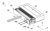
- FIG. 2 is a perspective view showing the configuration of the irradiation unit 10
- FIG. 3 is a perspective view showing a state in which the lamp unit 30 is being inserted into the housing 20 to configure the irradiation unit 10.
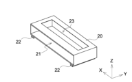
- FIG. . 4 is a perspective view showing the structure of the housing 20, and
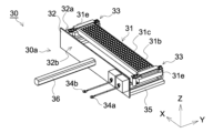
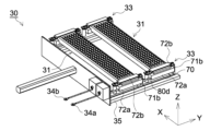
- FIG. 5 is a perspective view showing the structure of the lamp unit 30. As shown in FIG. In FIG. 4, the light extraction part 23, which will be described later, is not hatched so that the structure inside the housing 20 can be easily confirmed.
- the irradiation unit 10 includes a housing 20 and a lamp unit 30 as shown in FIGS. 2 and 3, and is configured by inserting the lamp unit 30 into the housing 20 as shown in FIG.
- the direction in which the ultraviolet light L1 is emitted from the irradiation unit 10 is the Z direction, and as shown in FIG. is the Y direction, and the direction orthogonal to the Y and Z directions is the X direction.
- the X direction corresponds to the "first direction”, the Y direction to the "second direction”, and the Z direction to the "third direction”.
- the housing 20 includes an insertion opening 21, a guide insertion portion 22, and a light extraction portion 23, as shown in FIG.
- the light extraction part 23 in this embodiment is an emission window covered with quartz glass.
- the light extraction part 23 may be an emission window covered with a material that transmits vacuum ultraviolet light, such as magnesium fluoride, instead of silica glass. Further, when it is desired to make the distance between the excimer lamp 31 mounted on the lamp unit 30 and the workpiece W1 closer than sealing the inside of the housing 20 and filling it with an inert gas, the light extraction part 23 is It may be a simple opening that is not covered with quartz glass or the like.
- the lamp unit 30 as shown in FIG. , and a handle 36 .
- the configuration of the lamp unit 30 excluding the excimer lamp 31 corresponds to the lamp holder 30a.
- Both ends (31e, 31e) of the excimer lamp 31 in this embodiment are supported by a pair of regulating members (33, 33) provided to protrude in the +Y direction from the first main surface 32a of the plate member 32.
- the arc tube 31c is configured to extend along the X direction.
- FIG. 6A is a drawing when the excimer lamp 31 is viewed in the Y direction
- FIG. 6B is a cross-sectional view when the excimer lamp 31 is cut along the YZ plane.
- the excimer lamp 31 has a rectangular cross-sectional shape when cut along the YZ plane.
- a pair of electrodes (31b, 31c) facing each other in the Z direction via 31c are formed.
- the ⁇ Z side electrode corresponds to the first electrode 31a
- the +Z side electrode corresponds to the second electrode 31b.
- a luminescent gas G1 containing Xe is sealed inside an arc tube 31c having a length of 0.4 m in the X direction, and the first electrode 31a and the second electrode 31b are separated from each other.
- ultraviolet light with a main emission wavelength of 172 nm is emitted.
- main emission wavelength refers to a wavelength showing a peak in an intensity spectrum.
- the lamp unit 30 in this embodiment may be mounted with an excimer lamp having a shape different from that of the excimer lamp 31 shown in FIGS. 6A and 6B.
- An excimer lamp having a shape called shape may be mounted.
- the luminescence gas G1 enclosed in the arc tube 31c may be a gas that does not contain Xe, and may be arbitrarily selected according to the intended use.
- the ultraviolet light emitted by the excimer lamp 31 preferably has a wavelength of 150 nm to 200 nm from the viewpoint of decomposing dirt such as oil and generating ozone.
- the excimer lamp 31 of the present embodiment emits ultraviolet light generated inside the arc tube 31c and propagating toward the ⁇ Z side on the inner wall surface 31q of the arc tube.
- a reflective film 31d made of silica (SiO 2 ) is formed. If the ultraviolet light generated in the arc tube 31c and traveling directly toward the +Z side can sufficiently perform the desired treatment, the excimer lamp 31 does not need to be formed with the reflective film 31d.
- the plate member 32 closes the insertion opening 21 of the housing 20 and seals the space inside the housing 20 when the lamp unit 30 is inserted into the housing 20 .
- the housing 20 whose inner space is sealed by the plate member 32 is filled with an inert gas (for example, nitrogen gas) during operation.
- an inert gas for example, nitrogen gas
- the housing 20 does not have to be sealed by the plate member 32 when the light extraction section 23 is not covered with quartz glass or the like and is an opening.
- the first power supply portion 34a and the second power supply portion 34b are provided so as to be aligned on the second main surface 32b side (-Y side) of the plate member 32, as shown in FIG.
- the first power supply portion 34a and the second power supply portion 34b are supplied with a high voltage from a power supply device (not shown) mounted in the ultraviolet light irradiation device 1.
- a power supply device not shown mounted in the ultraviolet light irradiation device 1.
- side terminal and low voltage side terminal, respectively. 5 the first power supply portion 34a and the second power supply portion 34b may be configured to be positioned on the -Y side of the plate member 32 via lead wires.
- a power supply terminal may be provided so as to protrude from the second main surface 32b to the -Y side.
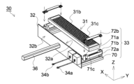
- FIG. 7 is a perspective view showing a state in which the excimer lamp 31 and the restricting member 33 are removed from the lamp unit 30, and FIG. 8 is a drawing when the lamp unit 30 is viewed from the X side.
- the guide member 35 in this embodiment is a rod-shaped member provided so as to protrude in the +Y direction from the first main surface 32a of the plate member 32, and is spaced apart in the X direction. and two are provided.
- the housing 20 is provided with two guide insertion portions 22 spaced apart in the X direction.
- the lamp unit 30 With the configuration in which the guide member 35 is inserted into the guide insertion portion 22 of the housing 20, the lamp unit 30 is guided to a predetermined insertion position of the housing 20 as shown in FIG. It is inserted straight in the Y direction without movement.
- the configuration of the guide insertion portion 22 shown in FIG. 4 and the configuration of the guide member 35 shown in FIG. 7 are merely examples, and the shape, number, etc. of the guide member 35 and the guide insertion portion 22 are arbitrary. Further, for example, when the housing 20 is configured to be sufficiently large and there is no possibility that the excimer lamp 31 and the housing 20 come into contact when the lamp unit 30 is inserted, the guide member 35 and the guide insertion portion 22 is optional.
- the grip portion 36 is a bar-shaped member having a length of 200 mm and protruding in the -Y direction from the second main surface 32b of the plate member 32. It is a part that an operator holds by hand when putting in and out of 20 . More preferably, the length of the handle portion 36 is 100 mm to 400 mm so that it is easy for a person to grip and does not get in the way.
- the handle portion 36 may be bent or curved so as to be easily gripped by a person, and may be partially provided with a convex portion or a concave portion so that a person's hand or fingers can easily be caught. I don't mind. Further, for example, if the plate member 32 has a portion for hooking a finger in order to pull out the lamp unit 30 from the housing 20, the handle portion 36 may not be provided. Furthermore, the grip portion 36 may be detachable from the housing 20 .
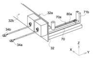
- FIG. 9 is a drawing showing a state in which the regulation member 33 is disassembled.
- the regulating member 33 in this embodiment includes a base member 70, a first strut 71a, a second strut 71b, a first clamping member 72a and a second clamping member 72b.
- the base member 70 is provided so as to protrude in the +Y direction from the first main surface 32a of the plate member 32, and is provided with a first support 71a so as to protrude in the +Z direction.
- the base member 70 also includes a second support 71b partially extending in the +Z direction, on the +Y side of the first support 71a, that is, at a position farther than the plate member 32. As shown in FIG.
- the regulating member 33 includes a first clamping member 72a and a second clamping member 72b that clamp the arc tube 31c of the excimer lamp 31 between the first support 71a and the second support 71b.
- the first holding member 72a and the second holding member 72b are configured such that the end portion of the arc tube 31c of the excimer lamp 31 is placed on the first holding member 72a, and the second holding member 72b is connected to the first support 71a and the second support.
- 71b is screwed and fixed to sandwich and support the arc tube 31c.
- the base member 70, the first strut 71a and the first holding member 72a are made of an insulating ceramic material, and the second strut 71b and the second holding member 72b are made of a metal material.
- the second strut 71b and the second clamping member 72b specifically, the second strut 71b is made of aluminum and the second clamping member 72b is made of stainless steel.
- the first holding member 72a is made of beryllium copper, which is a metallic material, and is in contact with the first electrode 31a (not shown in FIG. 9) when the arc tube 31c is placed.
- a plate spring 71c is mounted as a current-carrying member.
- the second support 71b in the present embodiment is entirely made of hard alumite, when the excimer lamp 31 is supported, the second electrode 31b and the second power supply portion 34b are electrically connected. , only a part thereof may be made of a metal material.
- FIG. 10A is a drawing of the periphery of the base member 70 of FIG. 9, and FIG. 10B is a drawing of the periphery of the base member 70 of FIG. 9 when viewed from an angle different from that of FIG. 10A.
- 10A and 10B do not show the first clamping member 72a and the second clamping member 72b for convenience of explanation.
- the first holding member 72a is not shown, and only the leaf spring 71c is virtually shown so that the current path from the first power supply portion 34a can be grasped.
- the base member 70 is formed with a groove 70a inside which the lead wire 80a is wired.
- the lead wire 80a is wired in the groove 70a of the base member 70 to electrically connect the second support 71b and the second power supply portion 34b.
- a metal plate 80c is connected between the second power supply portion 34b and the lead wire 80a for convenience of device configuration.
- the base member 70 in this embodiment is formed with a groove 70a for inserting the lead wire 80a, but may be formed with a through hole for inserting the lead wire 80a.
- the plate spring 71c is a member formed by bending a plate material made of beryllium copper, which is a metal material, and is electrically connected to the first power supply portion 34a via a lead wire 80b as shown in FIG. 10B. It is
- the irradiation unit 10 in this embodiment is mounted below the transport path 2 along which the work W1 is transported in the ultraviolet light irradiation device 1. 2 may be mounted above. [Another embodiment] Another embodiment will be described below.
- FIG. 11 is a perspective view schematically showing a lamp unit 30 provided in another embodiment of the irradiation unit 10.
- the regulating member 33 has a grip portion 33a, protrudes in the Y direction from the first main surface 32a of the plate member 32, and extends from both ends (31e, 31e) may be held.
- the grip portion 33a is made of an insulating member such as a ceramic material, and the electrodes (32a, 32b) and the power supply portions (34a, 34b) of the excimer lamp 31 are separated from each other by the regulating member. 33 are electrically connected via a lead wire, a metal plate, or the like (not shown) provided separately.
- the above configuration can be adopted when the voltage applied to the excimer lamp is relatively low, and even if the wiring inside the housing 20 is slightly misaligned, leakage current or the like will not occur in the wiring tube.
- FIG. 12 is a perspective view schematically showing a lamp unit 30 provided in another embodiment of the irradiation unit 10.
- the lamp unit 30 may have a plurality of excimer lamps 31 mounted thereon.
- the lamp unit 30 includes, for example, as shown in FIG. 12, a regulating member 33 in which the length of the base member 70 is adjusted according to the width at which the excimer lamp 31 is mounted.
- a lead wire 80d is provided for connecting a leaf spring 71c (not shown) mounted on a first holding member 72a provided for each excimer lamp 31.
- the second holding members 72b are connected to the corresponding second struts 71b, and the second struts 71b are connected by lead wires (not shown) wired inside the base member 70.
Landscapes
- Physics & Mathematics (AREA)
- Electromagnetism (AREA)
- Engineering & Computer Science (AREA)
- Plasma & Fusion (AREA)
- Chemical & Material Sciences (AREA)
- Organic Chemistry (AREA)
- Toxicology (AREA)
- General Health & Medical Sciences (AREA)
- Health & Medical Sciences (AREA)
- Chemical Kinetics & Catalysis (AREA)
- General Physics & Mathematics (AREA)
- Physical Or Chemical Processes And Apparatus (AREA)
- Cleaning Or Drying Semiconductors (AREA)
- Vessels And Coating Films For Discharge Lamps (AREA)
- Exposure And Positioning Against Photoresist Photosensitive Materials (AREA)
- Fastening Of Light Sources Or Lamp Holders (AREA)
- Cleaning In General (AREA)
Abstract
Description
このため、当該構成の紫外光照射装置では、紫外線ランプの交換時等に、ランプハウスの内壁面やフックに紫外線ランプを当ててしまい、紫外線ランプを破損してしまうことがあった。
第一方向に延伸する長尺状のエキシマランプと、
前記エキシマランプを搭載するランプホルダと、
挿入口を有し、前記ランプホルダが当該挿入口から挿入される筐体と、
前記筐体に設けられ、前記ランプホルダに搭載された前記エキシマランプから出射された紫外光を前記筐体の外側に取り出す光取り出し部と、
前記ランプホルダに設けられ、前記挿入口を閉塞する板材と、
前記板材が前記挿入口を閉塞する状態の下で、前記板材の主面のうち前記筐体の内側に位置する第一主面から突出するように形成された、前記筐体内における前記エキシマランプの移動を規制する規制部材と、
前記板材が前記挿入口を閉塞する状態の下で、前記筐体の外側に位置する前記板材の第二主面側に設けられ、前記エキシマランプに対して給電を行う給電部とを備えることを特徴とする。
前記エキシマランプは、相互に対向する平坦な一対の外壁面が形成された発光管と、前記発光管の当該一対の外壁面上に、前記発光管を介して対向するように形成された第一電極及び第二電極とを備えていても構わない。
前記規制部材は、前記板材の前記第一主面から、前記第一主面の法線方向である前記第二方向に突出する土台部材と、
前記第一方向及び前記第二方向に直交する第三方向に、前記土台部材から突出する第一支柱と、
前記第一支柱よりも前記板材から遠い位置において、前記土台部材から前記第一支柱と同じ方向に突出する第二支柱と、
前記第一支柱と前記第二支柱との間で、前記エキシマランプの端部を挟持する第一挟持部材及び第二挟持部材とを備え、
前記第二挟持部材が前記第一支柱及び前記第二支柱を接続するように固定される構成であっても構わない。
前記第一挟持部材と前記エキシマランプとの間に挟まれて前記エキシマランプが備える一対の電極のうちの一方の第一電極と接触する、金属材料で形成された通電部材と、
前記第二支柱と前記エキシマランプの前記第一電極とは別の第二電極とを電気的に接続する、前記土台部材に形成された溝又は貫通孔の内側で配線されたリード線とを備え、
前記第一挟持部材がセラミック材料、前記第二挟持部材及び前記第二支柱の少なくとも一部が金属材料で形成され、
前記第一挟持部材と前記第二挟持部材とが前記エキシマランプを挟持した状態で固定されると、前記給電部のうちの一方の第一給電部と前記第一電極とが前記通電部材を介して電気的に接続され、前記給電部の前記第一給電部とは別の第二給電部と前記第二電極とが、前記第二挟持部材、前記第二支柱及び前記リード線を介して電気的に接続されていても構わない。
前記板材は、前記第二主面から突出する把手部を備えていても構わない。
前記筐体に形成された、前記第一主面の法線方向である第二方向に延伸するガイド挿入部と、前記ガイド挿入部に挿入されることで前記ランプホルダの移動を規制する、前記板材に設けられた前記第二方向に延伸するガイド部材とを備えていても構わない。
前記筐体は、前記光取り出し部が、前記エキシマランプから出射される紫外光を透過する材料で覆われており、前記ランプホルダが挿入されて前記板材によって前記挿入口が閉塞されることで、前記筐体の内側の空間が密閉されるように構成されていても構わない。
上記照射ユニットに適用される、前記エキシマランプと前記ランプホルダとを備える。
上記照射ユニットが備えるランプホルダである。
図7及び図8に示すように、本実施形態におけるガイド部材35は、板材32の第一主面32aから+Y方向に突出するように設けられていた棒状の部材であって、X方向に離間して二つ設けられている。そして、筐体20は、図4に示すように、X方向に離間した二つのガイド挿入部22が設けられている。
[別実施形態]
以下、別実施形態につき説明する。
2 : 搬送路
10 : 照射ユニット
20 : 筐体
21 : 挿入口
22 : ガイド挿入部
23 : 光取り出し部
30 : ランプユニット
30a : ランプホルダ
31 : エキシマランプ
31a : 第一電極
31b : 第二電極
31c : 発光管
31d : 反射膜
31e : 端部
31p : 外壁面
31q : 内壁面
32 : 板材
32a : 第一主面
32b : 第二主面
33 : 規制部材
33a : 把持部
34a : 第一給電部
34b : 第二給電部
35 : ガイド部材
36 : 把手部
70 : 土台部材
70a : 溝
71a : 第一支柱
71b : 第二支柱
71c : 板バネ
72a : 第一挟持部材
72b : 第二挟持部材
80a,80b,80d : リード線
80c : 金属板
G1 : 発光ガス
L1 : 紫外光
W1 : ワーク
W1a : 照射面
Claims (9)
- 第一方向に延伸する長尺状のエキシマランプと、
前記エキシマランプを搭載するランプホルダと、
挿入口を有し、前記ランプホルダが当該挿入口から挿入される筐体と、
前記筐体に設けられ、前記ランプホルダに搭載された前記エキシマランプから出射された紫外光を前記筐体の外側に取り出す光取り出し部と、
前記ランプホルダに設けられ、前記挿入口を閉塞する板材と、
前記板材が前記挿入口を閉塞する状態の下で、前記板材の主面のうち前記筐体の内側に位置する第一主面から突出するように形成された、前記筐体内における前記エキシマランプの移動を規制する規制部材と、
前記板材が前記挿入口を閉塞する状態の下で、前記筐体の外側に位置する前記板材の第二主面側に設けられた、前記エキシマランプに対して給電を行う給電部とを備えることを特徴とする照射ユニット。 - 前記エキシマランプは、相互に対向する平坦な一対の外壁面が形成された発光管と、前記発光管の当該一対の外壁面上に、前記発光管を介して対向するように形成された第一電極及び第二電極とを備えることを特徴とする請求項1に記載の照射ユニット。
- 前記規制部材は、前記板材の前記第一主面から、前記第一主面の法線方向である第二方向に突出する土台部材と、
前記第一方向及び前記第二方向に直交する第三方向に、前記土台部材から突出する第一支柱と、
前記第一支柱よりも前記板材から遠い位置において、前記土台部材から前記第一支柱と同じ方向に突出する第二支柱と、
前記第一支柱と前記第二支柱との間で、前記エキシマランプの端部を挟持する第一挟持部材及び第二挟持部材とを備え、
前記第二挟持部材が前記第一支柱及び前記第二支柱を接続するように固定されることを特徴とする請求項1に記載の照射ユニット。 - 前記第一挟持部材と前記エキシマランプとの間に挟まれて前記エキシマランプが備える一対の電極のうちの一方の第一電極と接触する、金属材料で形成された通電部材と、
前記第二支柱と前記エキシマランプの前記第一電極とは別の第二電極とを電気的に接続する、前記土台部材に形成された溝又は貫通孔の内側で配線されたリード線とを備え、
前記第一挟持部材がセラミック材料、前記第二挟持部材及び前記第二支柱の少なくとも一部が金属材料で形成され、
前記第一挟持部材と前記第二挟持部材とが前記エキシマランプを挟持した状態で固定されると、前記給電部のうちの一方の第一給電部と前記第一電極とが前記通電部材を介して電気的に接続され、前記給電部の前記第一給電部とは別の第二給電部と前記第二電極とが、前記第二挟持部材、前記第二支柱及び前記リード線を介して電気的に接続されることを特徴とする請求項3に記載の照射ユニット。 - 前記板材は、前記第二主面から突出する把手部を備えることを特徴とする請求項1に記載の照射ユニット。
- 前記筐体に形成された、前記第一主面の法線方向である第二方向に延伸するガイド挿入部と、前記ガイド挿入部に挿入されることで前記ランプホルダの移動を規制する、前記板材に設けられた前記第二方向に延伸するガイド部材とを備えることを特徴とする請求項1に記載の照射ユニット。
- 前記筐体は、前記光取り出し部が、前記エキシマランプから出射される紫外光を透過する材料で覆われており、前記ランプホルダが挿入されて前記板材によって前記挿入口が閉塞されることで、前記筐体の内側の空間が密閉されることを特徴とする請求項1に記載の照射ユニット。
- 請求項1~7のいずれか一項に記載の照射ユニットが有する、前記エキシマランプと前記ランプホルダとを備えるランプユニット。
- 請求項1~7のいずれか一項に記載の照射ユニットが備えるランプホルダ。
Priority Applications (3)
| Application Number | Priority Date | Filing Date | Title |
|---|---|---|---|
| US18/729,358 US20250336663A1 (en) | 2022-01-25 | 2022-10-31 | Irradiation unit, lamp unit, and lamp holder |
| CN202280071474.8A CN118159356A (zh) | 2022-01-25 | 2022-10-31 | 照射单元、灯单元、灯座 |
| KR1020247011019A KR102956266B1 (ko) | 2022-01-25 | 2022-10-31 | 조사 유닛, 램프 유닛, 램프 홀더 |
Applications Claiming Priority (2)
| Application Number | Priority Date | Filing Date | Title |
|---|---|---|---|
| JP2022-009536 | 2022-01-25 | ||
| JP2022009536A JP7849659B2 (ja) | 2022-01-25 | 2022-01-25 | 照射ユニット、ランプユニット、ランプホルダ |
Publications (1)
| Publication Number | Publication Date |
|---|---|
| WO2023145178A1 true WO2023145178A1 (ja) | 2023-08-03 |
Family
ID=87471343
Family Applications (1)
| Application Number | Title | Priority Date | Filing Date |
|---|---|---|---|
| PCT/JP2022/040578 Ceased WO2023145178A1 (ja) | 2022-01-25 | 2022-10-31 | 照射ユニット、ランプユニット、ランプホルダ |
Country Status (6)
| Country | Link |
|---|---|
| US (1) | US20250336663A1 (ja) |
| JP (1) | JP7849659B2 (ja) |
| KR (1) | KR102956266B1 (ja) |
| CN (1) | CN118159356A (ja) |
| TW (1) | TWI914569B (ja) |
| WO (1) | WO2023145178A1 (ja) |
Citations (5)
| Publication number | Priority date | Publication date | Assignee | Title |
|---|---|---|---|---|
| JP2008104980A (ja) * | 2006-10-26 | 2008-05-08 | Harison Toshiba Lighting Corp | 紫外線照射装置 |
| JP2013105555A (ja) * | 2011-11-11 | 2013-05-30 | Ushio Inc | エキシマランプ |
| JP2015069734A (ja) * | 2013-09-27 | 2015-04-13 | ウシオ電機株式会社 | エキシマランプ装置および光照射処理装置 |
| JP2016137054A (ja) * | 2015-01-27 | 2016-08-04 | 株式会社オーク製作所 | エキシマランプを利用した表面処理装置 |
| JP2021103622A (ja) * | 2019-12-25 | 2021-07-15 | 株式会社オーク製作所 | エキシマランプおよびエキシマランプの管内設置方法 |
Family Cites Families (7)
| Publication number | Priority date | Publication date | Assignee | Title |
|---|---|---|---|---|
| ATE332477T1 (de) | 2002-02-12 | 2006-07-15 | Matsushita Electric Industrial Co Ltd | Beleuchtungsvorrichtung und diese verwendende flüssigkristallanzeigevorrichtung |
| TWI288945B (en) | 2003-03-12 | 2007-10-21 | Harison Toshiba Lighting Corp | Dielectric barrier discharge lamp tube and UV illumination device |
| JP4380591B2 (ja) | 2004-09-13 | 2009-12-09 | ウシオ電機株式会社 | エキシマランプ装置 |
| JP5171661B2 (ja) | 2009-01-20 | 2013-03-27 | シャープ株式会社 | Led照明器具 |
| JP2011177625A (ja) | 2010-02-26 | 2011-09-15 | Harison Toshiba Lighting Corp | 紫外線照射装置 |
| GB201107692D0 (en) | 2011-05-09 | 2011-06-22 | Snowball Malcolm R | Sterilisation of packed articles |
| JP5898891B2 (ja) | 2011-09-13 | 2016-04-06 | 浜松ホトニクス株式会社 | 発光装置 |
-
2022
- 2022-01-25 JP JP2022009536A patent/JP7849659B2/ja active Active
- 2022-10-25 TW TW111140377A patent/TWI914569B/zh active
- 2022-10-31 WO PCT/JP2022/040578 patent/WO2023145178A1/ja not_active Ceased
- 2022-10-31 CN CN202280071474.8A patent/CN118159356A/zh active Pending
- 2022-10-31 KR KR1020247011019A patent/KR102956266B1/ko active Active
- 2022-10-31 US US18/729,358 patent/US20250336663A1/en active Pending
Patent Citations (5)
| Publication number | Priority date | Publication date | Assignee | Title |
|---|---|---|---|---|
| JP2008104980A (ja) * | 2006-10-26 | 2008-05-08 | Harison Toshiba Lighting Corp | 紫外線照射装置 |
| JP2013105555A (ja) * | 2011-11-11 | 2013-05-30 | Ushio Inc | エキシマランプ |
| JP2015069734A (ja) * | 2013-09-27 | 2015-04-13 | ウシオ電機株式会社 | エキシマランプ装置および光照射処理装置 |
| JP2016137054A (ja) * | 2015-01-27 | 2016-08-04 | 株式会社オーク製作所 | エキシマランプを利用した表面処理装置 |
| JP2021103622A (ja) * | 2019-12-25 | 2021-07-15 | 株式会社オーク製作所 | エキシマランプおよびエキシマランプの管内設置方法 |
Also Published As
| Publication number | Publication date |
|---|---|
| US20250336663A1 (en) | 2025-10-30 |
| JP7849659B2 (ja) | 2026-04-22 |
| KR20240050442A (ko) | 2024-04-18 |
| CN118159356A (zh) | 2024-06-07 |
| KR102956266B1 (ko) | 2026-04-23 |
| TW202331786A (zh) | 2023-08-01 |
| TWI914569B (zh) | 2026-02-11 |
| JP2023108417A (ja) | 2023-08-04 |
Similar Documents
| Publication | Publication Date | Title |
|---|---|---|
| US6379024B1 (en) | Dielectric barrier excimer lamp and ultraviolet light beam irradiating apparatus with the lamp | |
| JP5311271B2 (ja) | エキシマランプ及び当該エキシマランプの製造方法 | |
| TWI453785B (zh) | 準分子燈、準分子燈單元及紫外線照射裝置 | |
| JP2023108417A (ja) | 照射ユニット、ランプユニット、ランプホルダ | |
| KR101255408B1 (ko) | 자외선 조사 장치 | |
| WO2013038859A1 (ja) | 発光装置 | |
| CN1750230B (zh) | 受激准分子灯装置 | |
| JP4957967B2 (ja) | 紫外線照射処理装置 | |
| JP2015069734A (ja) | エキシマランプ装置および光照射処理装置 | |
| TW201300177A (zh) | 紫外線照射裝置 | |
| JP4358571B2 (ja) | 除電装置 | |
| JP4829535B2 (ja) | X線発生装置及び照射ユニット | |
| CN214068692U (zh) | 紫外线照射装置 | |
| CN110690140A (zh) | 基板处理设备和喷嘴单元 | |
| CN214068693U (zh) | 紫外线照射装置 | |
| JP2018129413A (ja) | 光照射器および光照射装置 | |
| KR20220112186A (ko) | 엑시머 램프 | |
| JP7459673B2 (ja) | 紫外線照射装置 | |
| CN114365260A (zh) | 紫外线照射装置 | |
| JP2021051936A (ja) | バリア放電ランプおよび紫外線照射ユニット | |
| JP2009072645A (ja) | 紫外線照射装置 | |
| US20120248339A1 (en) | Light processing apparatus | |
| JP2001155686A (ja) | 誘電体バリアエキシマランプ | |
| CN112204704A (zh) | 准分子灯 | |
| CN101404188B (zh) | 紫外线照射装置 |
Legal Events
| Date | Code | Title | Description |
|---|---|---|---|
| 121 | Ep: the epo has been informed by wipo that ep was designated in this application |
Ref document number: 22924032 Country of ref document: EP Kind code of ref document: A1 |
|
| ENP | Entry into the national phase |
Ref document number: 20247011019 Country of ref document: KR Kind code of ref document: A |
|
| WWE | Wipo information: entry into national phase |
Ref document number: 202280071474.8 Country of ref document: CN |
|
| NENP | Non-entry into the national phase |
Ref country code: DE |
|
| 122 | Ep: pct application non-entry in european phase |
Ref document number: 22924032 Country of ref document: EP Kind code of ref document: A1 |
|
| WWP | Wipo information: published in national office |
Ref document number: 18729358 Country of ref document: US |
|
| WWG | Wipo information: grant in national office |
Ref document number: 1020247011019 Country of ref document: KR |