WO2023145023A1 - 媒体搬送装置、媒体給送方法及び制御プログラム - Google Patents
媒体搬送装置、媒体給送方法及び制御プログラム Download PDFInfo
- Publication number
- WO2023145023A1 WO2023145023A1 PCT/JP2022/003421 JP2022003421W WO2023145023A1 WO 2023145023 A1 WO2023145023 A1 WO 2023145023A1 JP 2022003421 W JP2022003421 W JP 2022003421W WO 2023145023 A1 WO2023145023 A1 WO 2023145023A1
- Authority
- WO
- WIPO (PCT)
- Prior art keywords
- medium
- roller
- motor
- feeding
- separation roller
- Prior art date
- Legal status (The legal status is an assumption and is not a legal conclusion. Google has not performed a legal analysis and makes no representation as to the accuracy of the status listed.)
- Ceased
Links
Images




Classifications
-
- B—PERFORMING OPERATIONS; TRANSPORTING
- B65—CONVEYING; PACKING; STORING; HANDLING THIN OR FILAMENTARY MATERIAL
- B65H—HANDLING THIN OR FILAMENTARY MATERIAL, e.g. SHEETS, WEBS, CABLES
- B65H3/00—Separating articles from piles
- B65H3/02—Separating articles from piles using friction forces between articles and separator
- B65H3/06—Rollers or like rotary separators
-
- B—PERFORMING OPERATIONS; TRANSPORTING
- B65—CONVEYING; PACKING; STORING; HANDLING THIN OR FILAMENTARY MATERIAL
- B65H—HANDLING THIN OR FILAMENTARY MATERIAL, e.g. SHEETS, WEBS, CABLES
- B65H3/00—Separating articles from piles
- B65H3/02—Separating articles from piles using friction forces between articles and separator
- B65H3/06—Rollers or like rotary separators
- B65H3/0607—Rollers or like rotary separators cooperating with means for automatically separating the pile from roller or rotary separator after a separation step
-
- B—PERFORMING OPERATIONS; TRANSPORTING
- B65—CONVEYING; PACKING; STORING; HANDLING THIN OR FILAMENTARY MATERIAL
- B65H—HANDLING THIN OR FILAMENTARY MATERIAL, e.g. SHEETS, WEBS, CABLES
- B65H3/00—Separating articles from piles
- B65H3/02—Separating articles from piles using friction forces between articles and separator
- B65H3/06—Rollers or like rotary separators
- B65H3/063—Rollers or like rotary separators separating from the bottom of pile
-
- B—PERFORMING OPERATIONS; TRANSPORTING
- B65—CONVEYING; PACKING; STORING; HANDLING THIN OR FILAMENTARY MATERIAL
- B65H—HANDLING THIN OR FILAMENTARY MATERIAL, e.g. SHEETS, WEBS, CABLES
- B65H3/00—Separating articles from piles
- B65H3/02—Separating articles from piles using friction forces between articles and separator
- B65H3/06—Rollers or like rotary separators
- B65H3/0669—Driving devices therefor
-
- B—PERFORMING OPERATIONS; TRANSPORTING
- B65—CONVEYING; PACKING; STORING; HANDLING THIN OR FILAMENTARY MATERIAL
- B65H—HANDLING THIN OR FILAMENTARY MATERIAL, e.g. SHEETS, WEBS, CABLES
- B65H3/00—Separating articles from piles
- B65H3/02—Separating articles from piles using friction forces between articles and separator
- B65H3/06—Rollers or like rotary separators
- B65H3/0676—Rollers or like rotary separators with two or more separator rollers in the feeding direction
-
- B—PERFORMING OPERATIONS; TRANSPORTING
- B65—CONVEYING; PACKING; STORING; HANDLING THIN OR FILAMENTARY MATERIAL
- B65H—HANDLING THIN OR FILAMENTARY MATERIAL, e.g. SHEETS, WEBS, CABLES
- B65H3/00—Separating articles from piles
- B65H3/02—Separating articles from piles using friction forces between articles and separator
- B65H3/06—Rollers or like rotary separators
- B65H3/0684—Rollers or like rotary separators on moving support, e.g. pivoting, for bringing the roller or like rotary separator into contact with the pile
-
- B—PERFORMING OPERATIONS; TRANSPORTING
- B65—CONVEYING; PACKING; STORING; HANDLING THIN OR FILAMENTARY MATERIAL
- B65H—HANDLING THIN OR FILAMENTARY MATERIAL, e.g. SHEETS, WEBS, CABLES
- B65H3/00—Separating articles from piles
- B65H3/66—Article guides or smoothers, e.g. movable in operation
-
- B—PERFORMING OPERATIONS; TRANSPORTING
- B65—CONVEYING; PACKING; STORING; HANDLING THIN OR FILAMENTARY MATERIAL
- B65H—HANDLING THIN OR FILAMENTARY MATERIAL, e.g. SHEETS, WEBS, CABLES
- B65H7/00—Controlling article feeding, separating, pile-advancing, or associated apparatus, to take account of incorrect feeding, absence of articles, or presence of faulty articles
- B65H7/02—Controlling article feeding, separating, pile-advancing, or associated apparatus, to take account of incorrect feeding, absence of articles, or presence of faulty articles by feelers or detectors
- B65H7/06—Controlling article feeding, separating, pile-advancing, or associated apparatus, to take account of incorrect feeding, absence of articles, or presence of faulty articles by feelers or detectors responsive to presence of faulty articles or incorrect separation or feed
- B65H7/12—Controlling article feeding, separating, pile-advancing, or associated apparatus, to take account of incorrect feeding, absence of articles, or presence of faulty articles by feelers or detectors responsive to presence of faulty articles or incorrect separation or feed responsive to double feed or separation
-
- B—PERFORMING OPERATIONS; TRANSPORTING
- B65—CONVEYING; PACKING; STORING; HANDLING THIN OR FILAMENTARY MATERIAL
- B65H—HANDLING THIN OR FILAMENTARY MATERIAL, e.g. SHEETS, WEBS, CABLES
- B65H2515/00—Physical entities not provided for in groups B65H2511/00 or B65H2513/00
- B65H2515/30—Forces; Stresses
- B65H2515/32—Torque e.g. braking torque
-
- B—PERFORMING OPERATIONS; TRANSPORTING
- B65—CONVEYING; PACKING; STORING; HANDLING THIN OR FILAMENTARY MATERIAL
- B65H—HANDLING THIN OR FILAMENTARY MATERIAL, e.g. SHEETS, WEBS, CABLES
- B65H2801/00—Application field
- B65H2801/03—Image reproduction devices
- B65H2801/12—Single-function printing machines, typically table-top machines
Definitions
- the present disclosure relates to a medium transporting device, a medium feeding method, and a control program.
- a medium conveying device such as a scanner that sequentially feeds and images a plurality of media while separating them, it is required to separate the media better so as not to cause double feeding of the media.
- a document separation device includes a feed roller, a reverse roller, a lever that detects a document on a document table, and a reading motor that rotates the reverse roller based on detection information from the lever (see Japanese Patent Application Laid-Open No. 2002-200013). reference).
- This document separation device rotates the reverse roller without rotating the feed roller when the reading motor detects the document on the document table by means of the lever.
- a feeding device includes a supporting portion that supports a medium set in a setting portion and that moves so that the medium and the feeding roller come into contact with each other when the medium is fed by the feeding roller (see Patent Document 2: reference).
- the feeding device drives the feeding roller prior to the movement of the supporting portion.
- a medium conveying device, a medium feeding method, and a control program according to embodiments aim to separate media more satisfactorily.
- a medium conveying device includes a feed roller for feeding a medium, a separation roller arranged to face the feed roller, and a medium contacting the feed roller and the separation roller.
- a regulating guide movably provided between a regulating first position and a second position not regulating contact of the medium with the feeding roller and the separation roller; and a first motor for driving the feeding roller.
- a second motor for driving the separation roller;
- a third motor for moving the regulation guide; a controller for controlling the first motor, the second motor and the third motor to rotate.
- a medium conveying device includes a feed roller for feeding a medium, a separation roller arranged to face the feed roller, and a medium contacting the feed roller and the separation roller.
- a regulating guide movably provided between a regulating first position and a second position not regulating contact of the medium with the feeding roller and the separation roller; and a first motor for driving the feeding roller.
- a second motor for driving the separation roller and moving the regulating guide; and a control unit that controls the first motor and the second motor.
- a medium is fed by a feeding roller, and a separation roller arranged to face the feeding roller in a rotating state at the start of feeding the medium.
- a regulation guide is movably provided between a first position that regulates contact with the separation roller arranged opposite to the medium and a second position that does not regulate contact of the medium with the feeding roller and the separation roller. control the third motor for
- a medium is fed by a feeding roller, and a separation roller arranged to face the feeding roller in a rotating state at the start of feeding the medium.
- a control program includes a feed roller for feeding a medium, a separation roller arranged to face the feed roller, and regulating contact of the medium with the feed roller and the separation roller.
- a regulating guide movably provided between a first position where the medium is not restricted from contacting the feeding roller and the separation roller; a first motor for driving the feeding roller;
- a control program for a medium conveying device having a second motor for driving a separation roller and a third motor for moving a regulation guide, wherein the separation roller is in a rotating state at the start of medium feeding causes the media transport device to control the first motor, the second motor, and the third motor such that the feed roller rotates after the contact with the media.
- a control program includes a feed roller for feeding a medium, a separation roller arranged to face the feed roller, and regulating contact of the medium with the feed roller and the separation roller.
- a regulating guide movably provided between a first position where the medium is not restricted from contacting the feeding roller and the separation roller; a first motor for driving the feeding roller; and a second motor for driving the separation roller and moving the regulating guide, wherein the separation roller in a rotating state contacts the medium at the start of feeding the medium. causes the media transport device to control the first motor and the second motor such that the feed roller rotates from the
- the medium conveying device, medium feeding method, and control program can separate the medium more satisfactorily.
- FIG. 1 is a perspective view showing a medium conveying device 100 according to an embodiment
- FIG. 4 is a diagram for explaining a transport path inside the medium transport device 100
- FIG. 11 is a schematic diagram for explaining a restriction guide 112 and the like
- FIG. 11 is a schematic diagram for explaining the operation of the regulation guide 112 and the like
- FIG. 3 is a schematic diagram for explaining a housing portion 134
- 1 is a block diagram showing a schematic configuration of a medium conveying device 100
- FIG. 2 is a diagram showing a schematic configuration of a storage device 140 and a processing circuit 150
- FIG. 7 is a flow chart showing an example of the operation of medium reading processing; 7 is a flow chart showing an example of the operation of medium reading processing; 7 is a graph for explaining speed changes of the feeding roller 115 and the like; 7 is a flow chart showing an example of the operation of multi-feeding determination processing;
- FIG. 10 is a schematic diagram for explaining the operation of returning the medium to the mounting table 103;
- FIG. 11 is a diagram for explaining a transport path inside another medium transport device 200;
- 3 is a diagram showing a schematic configuration of another processing circuit 350;
- FIG. 1 is a perspective view showing a medium conveying device 100 configured as an image scanner.
- the medium conveying device 100 conveys a medium, which is an original, and captures an image.
- the medium may be paper, thin paper, cardboard, card, booklet, passport, or the like.
- the media transport device 100 may be a facsimile machine, a copier, a multifunction peripheral (MFP), or the like.
- MFP multifunction peripheral
- the medium to be conveyed may be an object to be printed instead of a document, and the medium conveying device 100 may be a printer or the like.
- the medium transport device 100 includes a lower housing 101, an upper housing 102, a mounting table 103, a discharge table 104, an operation device 105, a display device 106, and the like.
- arrow A1 indicates the medium transport direction
- arrow A2 indicates the width direction orthogonal to the medium transport direction
- arrow A3 indicates the height direction orthogonal to the medium transport path.
- upstream refers to upstream in the medium transport direction A1
- downstream refers to downstream in the medium transport direction A1.
- the upper housing 102 is arranged to cover the upper surface of the medium transporting device 100, and is engaged with the lower housing 101 by a hinge so that it can be opened and closed when the medium is clogged, when cleaning the inside of the medium transporting device 100, or the like.
- the mounting table 103 engages with the lower housing 101 and mounts a medium to be fed and conveyed.
- the ejection table 104 engages with the upper housing 102 and places the ejected medium. Note that the discharge table 104 may be engaged with the lower housing 101 .
- the operation device 105 has an input device such as a button and an interface circuit that acquires signals from the input device, receives an input operation by the user, and outputs an operation signal according to the user's input operation.
- the display device 106 has a display including liquid crystal, organic EL (Electro-Luminescence), etc. and an interface circuit for outputting image data to the display, and displays the image data on the display.
- FIG. 2 is a diagram for explaining the transport path inside the medium transport device 100.
- FIG. 2 is a diagram for explaining the transport path inside the medium transport device 100.
- the transport path inside the medium transport device 100 includes a first medium sensor 111, a regulation guide 112, a cam member 113, a flap 114, a feed roller 115, a separation roller 116, a second medium sensor 117, an ultrasonic sensor 118, and a transport roller 119. , a first opposed roller 120, a third medium sensor 121, an imaging device 122, a discharge roller 123, a second opposed roller 124, and the like.
- each of the feed roller 115, the separation roller 116, the transport roller 119, the first opposing roller 120, the discharge roller 123 and/or the second opposing roller 124 is not limited to one, and may be plural.
- the plurality of feeding rollers 115, separation rollers 116, conveying rollers 119, first facing rollers 120, discharge rollers 123 and/or second facing rollers 124 are spaced apart in the width direction A2 orthogonal to the medium conveying direction. Arranged side by side with space.
- the upper surface of the lower housing 101 forms the lower guide 101a of the medium transport path
- the lower surface of the upper housing 102 forms the upper guide 102a of the medium transport path.
- the first medium sensor 111 is arranged upstream from the feed roller 115 and the separation roller 116 .
- the first medium sensor 111 has a contact detection sensor and detects whether or not a medium is mounted on the mounting table 103 .
- the first medium sensor 111 generates and outputs a medium signal whose signal value changes depending on whether the medium is mounted on the mounting table 103 or not.
- the first medium sensor 111 is not limited to a contact detection sensor, and any other sensor capable of detecting the presence or absence of a medium, such as a light detection sensor, may be used as the first medium sensor 111 .
- the feeding roller 115 is provided in the lower housing 101, and separates and feeds the media placed on the placing table 103 in order from the bottom.
- the separation roller 116 is a so-called brake roller or retard roller, is provided in the upper housing 102 , and is arranged to face the feeding roller 115 .
- the separation roller 116 is provided rotatably or stopably in the direction opposite to the medium feeding direction. Note that the feeding roller 115 is provided in the upper housing 102 and the separating roller 116 is provided in the lower housing 101, and the feeding roller 115 may feed the medium placed on the mounting table 103 in order from the upper side. good.
- the second medium sensor 117 is arranged downstream from the feed roller 115 and upstream from the transport roller 119, and detects the medium transported to that position.
- the second medium sensor 117 includes a light emitter and a light receiver provided on one side with respect to the medium transport path, and a light guide tube provided at a position facing the light emitter and the light receiver across the medium transport path.
- the light emitter is an LED (Light Emitting Diode) or the like, and emits light toward the medium transport path.
- the light receiver is a photodiode or the like, and receives light emitted by the light emitter and guided by the light guide tube.
- the second medium sensor 117 When a medium exists at a position facing the second medium sensor 117, the light emitted from the light emitter is blocked by the medium, so the light receiver does not detect the light emitted from the light emitter.
- the second medium sensor 117 generates a second medium signal whose signal value changes depending on whether or not the medium is present at the position of the second medium sensor 117 based on the intensity of the light received by the light receiver. output.
- a reflecting member such as a mirror may be used instead of the light guide tube.
- the light emitter and the light receiver may be provided facing each other across the medium transport path.
- the second medium sensor 117 may detect the presence of the medium by a contact detection sensor or the like that causes a predetermined current to flow when the medium is in contact or when the medium is not in contact.
- the ultrasonic sensor 118 is arranged downstream from the feed roller 115 , particularly downstream from the second medium sensor 117 and upstream from the transport roller 119 .
- the ultrasonic sensor 118 includes an ultrasonic transmitter 118a and an ultrasonic receiver 118b.
- the ultrasonic transmitter 118a and the ultrasonic receiver 118b are arranged in the vicinity of the transport path of the medium so as to face each other with the transport path interposed therebetween.
- the ultrasonic transmitter 118a transmits ultrasonic waves.
- the ultrasonic receiver 118b receives ultrasonic waves transmitted by the ultrasonic transmitter 118a and transmitted through a medium, and generates and outputs ultrasonic signals, which are electrical signals corresponding to the received ultrasonic waves.
- the medium transport device 100 can detect double feeding of the medium based on the ultrasonic signal.
- the transport roller 119 and the first opposing roller 120 are arranged downstream of the feed roller 115 and the separation roller 116 in the medium transport direction A1, facing each other.
- the conveying roller 119 is provided in the upper housing 102 and conveys the medium fed by the feeding roller 115 and separation roller 116 to the imaging device 122 .
- the conveying roller 119 may be provided in the lower housing 101 and the first opposing roller 120 may be provided in the upper housing 102 .
- the third medium sensor 121 is arranged downstream from the conveying roller 119 and upstream from the imaging device 122, and detects the medium conveyed to that position.
- the third medium sensor 121 includes a light emitter and a light receiver provided on one side with respect to the medium transport path, and a light guide tube provided at a position facing the light emitter and the light receiver across the medium transport path. including.
- the light emitter is an LED or the like, and emits light toward the medium transport path.
- the light receiver is a photodiode or the like, and receives light emitted by the light emitter and guided by the light guide tube.
- the third medium sensor 121 generates a third medium signal whose signal value changes depending on whether or not the medium is present at the position of the third medium sensor 121 based on the intensity of the light received by the light receiver. output.
- a reflecting member such as a mirror may be used instead of the light guide tube.
- the light emitter and the light receiver may be provided facing each other across the medium transport path.
- the third medium sensor 121 may detect the presence of the medium by a contact detection sensor or the like that causes a predetermined current to flow when the medium is in contact or when the medium is not in contact.
- the imaging device 122 is an example of an imaging unit, is arranged downstream of the transport roller 119 and the first opposing roller 120 in the medium transport direction A1, and images the medium transported by the transport roller 119 and the first opposing roller 120. do.
- the image pickup device 122 includes a first image pickup device 122a and a second image pickup device 122b arranged to face each other across the medium transport path.
- the first imaging device 122a has a linear optical system type CIS (Contact Image Sensor) line sensor having CMOS (Complementary Metal Oxide Semiconductor) imaging elements linearly arranged in the main scanning direction.
- the first imaging device 122a also has a lens that forms an image on the imaging element, and an A/D converter that amplifies an electrical signal output from the imaging element and performs analog/digital (A/D) conversion.
- the first imaging device 122a captures an image of the surface of the medium being conveyed, generates an input image, and outputs the input image, under control from a processing circuit to be described later.
- the second imaging device 122b has a CIS line sensor of the same magnification optical system type having CMOS imaging elements linearly arranged in the main scanning direction. Also, the second imaging device 122b has a lens that forms an image on the imaging device, and an A/D converter that amplifies the electrical signal output from the imaging device and performs analog/digital (A/D) conversion.
- the second image capturing device 122b captures an image of the back surface of the medium being conveyed, generates an input image, and outputs the input image, under the control of a processing circuit, which will be described later.
- the medium conveying device 100 may have only one of the first imaging device 122a and the second imaging device 122b and read only one side of the medium.
- a line sensor of the same magnification optical system type CIS provided with the CMOS imaging device a line sensor of the same magnification optical system type CIS provided with the CCD (Charge Coupled Device) imaging device may be used.
- a reduction optics type line sensor having a CMOS or CCD imaging device may be used.
- the discharge roller 123 and the second opposing roller 124 are arranged facing each other downstream from the imaging device 122, that is, from the transport roller 119 and the first opposing roller 120 in the medium transport direction A1.
- the discharge roller 123 is provided in the upper housing 102 , conveys the medium conveyed by the conveying roller 119 and the first opposing roller 120 further downstream, and discharges the medium onto the discharge table 104 .
- the discharge roller 123 may be provided in the lower housing 101 and the second facing roller 124 may be provided in the upper housing 102 .
- the medium conveying device 100 has, as feeding modes, a separation mode in which the medium is fed while being separated, and a non-separation mode in which the medium is fed without being separated.
- the feeding mode is set by the user using the operation device 105 or the information processing device that communicates with the medium conveying device 100 .
- the separation roller 116 rotates or stops in the direction of arrow A5, ie, the direction opposite to the medium feeding direction.
- the medium is fed between the conveying roller 119 and the first opposing roller 120 while being guided by the lower guide 101a and the upper guide 102a.
- the medium is fed between the first imaging device 122a and the second imaging device 122b by rotating the transport roller 119 and the first opposing roller 120 in the directions of arrows A6 and A7, respectively.
- the medium read by the imaging device 122 is ejected onto the ejection table 104 as the ejection roller 123 and the second opposing roller 124 rotate in the directions of arrows A8 and A9, respectively.
- the medium conveying device 100 has a first motor 131, a second motor 132 and a third motor 133 as drive sources for the rollers.
- the first motor 131 is provided in the lower housing 101, is connected to the feed roller 115 via the first transmission mechanism 131a, and drives the feed roller 115.
- the first motor 131 generates driving force for driving the feeding roller 115 according to a control signal from the processing circuit.
- the first transmission mechanism 131a includes one or more pulleys, belts, gears, or the like provided between the first motor 131 and the shaft 115a that is the rotating shaft of the feeding roller 115.
- the first motor 131 generates The applied driving force is transmitted to the feeding roller 115 .
- the first motor 131 rotates the feeding roller 115 to feed the medium.
- the first motor 131 may be arranged in the upper housing 102 .
- the second motor 132 is provided in the upper housing 102 separately from the first motor 131, is connected to the separation roller 116 via a second transmission mechanism 132a, and drives the separation roller 116.
- the second motor 132 generates driving force for driving the separation roller 116 according to control signals from the processing circuit.
- the second transmission mechanism 132 a includes one or more pulleys, belts, gears, etc. provided between the second motor 132 and the shaft 116 a that is the rotation axis of the separation roller 116 .
- the second transmission mechanism 132 a transmits the driving force generated by the second motor 132 to the separation roller 116 .
- the second motor 132 rotates the separation roller 116 to cause the separation roller 116 to separate, feed, and convey the medium.
- the second motor 132 may be arranged in the lower housing 101 .
- the third motor 133 is provided in the upper housing 102 separately from the first motor 131 and the second motor 132 .
- the third motor 133 is connected to the transport roller 119 , the discharge roller 123 and the cam member 113 via the third transmission mechanism 133 a to drive the transport roller 119 , the discharge roller 123 and the cam member 113 .
- the third motor 133 generates driving force for driving the conveying roller 119, the discharge roller 123 and the cam member 113 according to the control signal from the processing circuit.
- the third transmission mechanism 133 a is provided between the third motor 133 , the shaft 119 a that is the rotation shaft of the transport roller 119 , the shaft 123 a that is the rotation shaft of the discharge roller 123 , and the rotation shaft 113 a of the cam member 113 . or multiple pulleys, belts, gears, etc.
- the third transmission mechanism 133 a transmits the driving force generated by the third motor 133 to the conveying roller 119 , the discharge roller 123 and the cam member 113 . Thereby, the third motor 133 rotates the transport roller 119 and the discharge roller 123 to transport and discharge the medium by the transport roller 119 and the discharge roller 123 .
- the conveying roller 119 and the discharge roller 123 are provided so as to be driven by the third motor 133 .
- the third motor 133 rotates the cam member 113 to move the regulation guide 112 that contacts the cam member 113 .
- the third motor 133 may be arranged in the lower housing 101 .
- a common motor is used as a motor for driving the transport roller 119 and the discharge roller 123, and a motor for moving the regulation guide 112.
- the medium transporting device 100 can reduce the number of motors, thereby reducing the cost and weight of the device.
- the first facing roller 120 is a driven roller driven to rotate by the transport roller 119
- the second facing roller 124 is a driven roller to rotate driven by the discharge roller 123
- the first opposing roller 120 and/or the second opposing roller 124 may be provided so as to be driven by the driving force from the third motor 133 .
- One or more gears are also provided between the shaft 119a of the transport roller 119 and the shaft 120a that is the rotation axis of the first opposing roller 120 and/or between the shaft 123a of the discharge roller 123 and the shaft 124a that is the rotation axis of the second opposing roller 124.
- One or more gears are also provided.
- the third transmission mechanism 133 a further transmits the driving force generated by the third motor 133 to the first facing roller 120 and/or the second facing roller 124 .
- FIG. 3 is a schematic diagram for explaining the regulation guide 112, the cam member 113 and the flap 114.
- FIG. FIG. 3 is a schematic side view of the regulation guide 112, the cam member 113, and the flap 114 before the medium is fed.
- the regulation guide 112 is a guide for setting the medium (group) M1 mounted on the mounting table 103. As shown in FIG. The regulation guide 112 is arranged at a position facing the feed roller 115 and the separation roller 116 in the medium transport direction A1. The regulation guide 112 is rotatably (swingably) supported by the lower housing 101, and supports the lower surface of the medium M1 placed on the placing table 103 when the medium M1 is not being fed.
- the position at which the regulation guide 112 supports the lower surface of the medium M1 placed on the placement table 103 may be referred to as a set position.
- the cam member 113 is a moving member for moving the regulation guide 112 .
- the cam member 113 is arranged downstream of the regulation guide 112 in the medium transport direction A1.
- the cam member 113 is rotatable (swingable) by the third motor 133 .
- the cam member 113 is rotatably supported by the lower housing 101 according to the driving force from the third motor 133, and comes into contact with the downstream end of the regulation guide 112 when the medium is not being fed. to hold the restriction guide 112 at the set position.
- the flap 114 is a stopper for preventing the medium M1 from entering the nip portion between the feed roller 115 and the separation roller 116 before the medium is fed.
- the flap 114 is arranged at a position facing the regulation guide 112 in the medium transport direction A1.
- the flap 114 is swingably provided on the upper housing 102, and when the medium M1 is not being fed, the flap 114 is engaged with the regulation guide 112 arranged at the set position to separate the feeding roller 115 and the separation roller. Entry of the medium M1 into the nip portion of 116 is blocked.
- the regulation guide 112 regulates the contact of the medium M1 with the feed roller 115 and the separation roller 116 at the set position.
- the set position is an example of the first position.
- FIG. 4A and 4B are schematic diagrams for explaining the operations of the regulation guide 112, the cam member 113 and the flap 114.
- FIG. FIG. 4 is a schematic side view of the regulating guide 112, the cam member 113, and the flap 114 during medium feeding.
- the cam member 113 swings (rotates) downward (in the direction of the arrow A11) according to the driving force from the third motor 133, and is regulated. It is spaced from the downstream end of the guide 112 .
- the downstream end of the regulation guide 112 moves away from the cam member 113 and is no longer held by the cam member 113 , thereby swinging downward (in the direction of the arrow A 12 ) from the medium conveying surface and onto the mounting table 103 . It is separated from the lower surface of the placed medium M1.
- the position where the regulation guide 112 is separated from the lower surface of the medium M1 placed on the placement table 103 may be referred to as the release position.
- the engagement between the flap 114 and the regulation guide 112 is released by disposing the regulation guide 112 at the release position.
- the flap 114 is pushed by the leading edge of the medium M1 placed on the platform 103 and swings downstream (in the direction of the arrow A13). It becomes possible to enter the nip portion.
- the flap 114 allows the medium M1 to enter the nip portion between the feed roller 115 and the separation roller 116 when the regulation guide 112 is arranged at the release position.
- the restriction guide 112 does not restrict the medium M1 from contacting the feed roller 115 and the separation roller 116 at the release position.
- the release position is an example of a second position.
- the regulation guide 112 is provided movably between the set position and the release position.
- the regulation guide 112 is provided so as to move when the cam member 113 rotates.
- the feed roller 115 is provided with an outer peripheral surface 115b, a one-way clutch 115c, and the like.
- the one-way clutch 115 c is arranged on the shaft 115 a that is the rotating shaft of the feeding roller 115 .
- the one-way clutch 115c prevents (the outer peripheral surface 115b of) the feeding roller 115 from rotating in the direction opposite to the medium feeding direction A4 with respect to the shaft 115a. This prevents the feeding roller 115 from rotating in the direction opposite to the medium feeding direction A4 by being dragged by the separation roller 116 rotating in the direction A5 opposite to the medium feeding direction.
- the conveying roller 119 conveys the medium at a conveying speed faster than the feeding speed of the feeding roller 115 . Therefore, when the medium reaches the position of the transport roller 119 , the medium is pinched between the feed roller 115 and the separation roller 116 and pulled by the transport roller 119 . At this time, the outer peripheral surface 115b of the feeding roller 115 rotates according to the nipped medium due to the action of the one-way clutch 115c, and does not hinder the transportation of the medium. Note that the conveying roller 119 may convey the medium at the same conveying speed as the feeding speed of the feeding roller 115 .
- the separation roller 116 is provided with an outer peripheral surface 116b, a torque limiter 116c, and the like.
- the torque limiter 116c is arranged on the shaft 116a, which is the rotating shaft of the separation roller 116. As shown in FIG. Torque limiter 116 c regulates the maximum torque applied to separation roller 116 .
- the limit value of the torque limiter 116c is set to such a value that the torque via the torque limiter 116c is cut off when there is one medium, and the torque via the torque limiter 116c is transmitted when there are multiple mediums. be. As a result, when only one medium is conveyed, the separation roller 116 does not rotate according to the driving force from the second motor 132 but follows the feeding roller 115 .
- the separating roller 116 rotates in the direction A5 opposite to the medium feeding direction, and separates the medium in contact with the feeding roller 115 from the other media, thereby feeding multiple media. prevent the occurrence of At this time, the outer peripheral surface 116b of the separation roller 116 may apply the force in the direction A5 opposite to the medium feeding direction to the medium in a state where the outer peripheral surface 116b does not rotate in the direction A5 opposite to the medium feeding direction but stops.
- FIG. 5 is a schematic diagram for explaining the housing portion 134.
- the housing portion 134 is provided in the lower housing 101 .
- the storage unit 134 stores adherents such as paper dust or dust adhering to the medium being conveyed, or adherents adhering to the feeding roller 115 or the separation roller 116 from the medium being conveyed.
- a lower guide 101a which is a medium guide surface of the lower housing 101, has an opening 101b for arranging the feeding roller 115.
- the storage unit 134 is arranged below the feeding roller 115 so as to face the opening 101b, and the medium to be transported falls from the feeding roller 115 or the separation roller 116, and falls between the feeding roller 115 and the opening 101b.
- the storage unit 134 is provided detachably from the lower housing 101 , that is, from the medium conveying device 100 .
- the storage unit 134 allows the medium conveying device 100 to appropriately collect paper dust or dust, and to prevent paper dust or dust from accumulating in the medium transport path.
- FIG. 6 is a block diagram showing a schematic configuration of the medium conveying device 100. As shown in FIG.
- the medium transport device 100 further includes an interface device 135, a storage device 140, a processing circuit 150, and the like, in addition to the configuration described above.
- the interface device 135 has an interface circuit conforming to a serial bus such as USB, for example, and is electrically connected to an information processing device (not shown) (for example, a personal computer, a mobile information terminal, etc.) to receive an input image and various information. Send and receive.
- an information processing device for example, a personal computer, a mobile information terminal, etc.
- a communication unit having an antenna for transmitting and receiving wireless signals and a wireless communication interface device for transmitting and receiving signals through a wireless communication line according to a predetermined communication protocol may be used.
- the predetermined communication protocol is, for example, a wireless LAN (Local Area Network).
- the communication unit may have a wired communication interface device for transmitting and receiving signals through a wired communication line according to a communication protocol such as a wired LAN.
- the storage device 140 includes memory devices such as RAM (Random Access Memory) and ROM (Read Only Memory), fixed disk devices such as hard disks, or portable storage devices such as flexible disks and optical disks.
- the storage device 140 also stores computer programs, databases, tables, and the like used for various processes of the medium transport device 100 .
- the computer program may be installed in the storage device 140 from a computer-readable portable recording medium using a known setup program or the like.
- Portable recording media are, for example, CD-ROMs (compact disc read only memory), DVD-ROMs (digital versatile disc read only memory), and the like.
- the processing circuit 150 operates based on a program stored in the storage device 140 in advance.
- the processing circuit is, for example, a CPU (Central Processing Unit).
- a DSP digital signal processor
- LSI large scale integration
- ASIC Application Specific Integrated Circuit
- FPGA Field-Programmable Gate Array
- the processing circuit 150 includes the operation device 105, the display device 106, the first medium sensor 111, the second medium sensor 117, the ultrasonic sensor 118, the third medium sensor 121, the imaging device 122, the first motor 131, the second motor 132, It is connected to the third motor 133, the interface device 135, the storage device 140, etc., and controls these parts.
- the processing circuit 150 performs driving control of each motor, imaging control of the imaging device 122, and the like, based on each medium signal received from each medium sensor.
- the processing circuit 150 acquires an input image from the imaging device 122 and transmits it to the information processing device via the interface device 135 .
- the processing circuit 150 determines whether or not double feeding of media has occurred based on the ultrasonic signal received from the ultrasonic sensor 118 , and if double feeding of media has occurred, the medium is placed on the mounting table 103 . Control each motor to return.
- FIG. 7 is a diagram showing a schematic configuration of the storage device 140 and the processing circuit 150. As shown in FIG.
- the storage device 140 stores a control program 141, a determination program 142, and the like. Each of these programs is a functional module implemented by software running on a processor.
- the processing circuit 150 reads each program stored in the storage device 140 and operates according to each read program. Thereby, the processing circuit 150 functions as a control section 151 and a determination section 152 .
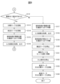
- FIG. 8 and 9 are flowcharts showing an example of the operation of the medium reading process of the medium conveying device 100.
- FIG. 8 and 9 are flowcharts showing an example of the operation of the medium reading process of the medium conveying device 100.
- control unit 151 receives an instruction to read a medium from the operation device 105 or the interface device 135 when a user inputs an instruction to read the medium using the operation device 105 or the information processing device. (step S101).
- control unit 151 acquires a medium signal from the first medium sensor 111, and determines whether or not a medium is placed on the placing table 103 based on the acquired medium signal (step S102). If no medium is placed on the placing table 103, the control unit 151 terminates the series of steps.
- the control unit 151 first drives the third motor 133 (step S103).
- the control unit 151 rotates the cam member 113 in the direction of arrow A11 in FIG. 3 to rotate the regulation guide 112 in the direction of arrow A12 in FIG. move to
- the control unit 151 drives the third motor 133 to move the conveying roller 119, the first facing roller 120, the discharge roller 123 and/or the second facing roller 124 to the directions indicated by the arrows A6, A7 and A8 in FIG. 2, respectively. and/or rotate in the direction of A9.
- control unit 151 drives the second motor 132 to rotate the separation roller 116 in the direction opposite to the medium feeding direction (in the direction of arrow A5 in FIG. 2) (step S104).
- control unit 151 drives the first motor 131 to rotate the feeding roller 115 in the medium feeding direction (in the direction of the arrow A4 in FIG. 2) to feed the medium (step S105). ).
- FIG. 10 is a graph for explaining speed changes of the feed roller 115, the separation roller 116, and the transport roller 119.
- FIG. 10 is a graph for explaining speed changes of the feed roller 115, the separation roller 116, and the transport roller 119.
- a graph G11 shows the speed change of the feed roller 115
- a graph G12 shows the speed change of the separation roller 116
- a graph G13 shows the speed change of the transport roller 119. Since the speeds of the first facing roller 120, the discharge roller 123, and the second facing roller 124 change in the same manner as the speed of the transport roller 119, the change in speed of the transport roller 119 will be described below as a representative example.
- the horizontal axis of each graph G11 to G13 indicates time, and the vertical axis indicates speed.
- the graph G14 shows changes in the signal value of the second medium sensor 117
- the graph G15 shows changes in the signal value of the third medium sensor 121.
- the horizontal axis of each graph G14 and G15 indicates time, and the vertical axis indicates signal value.
- the signal value of the corresponding signal is L when the medium is not present at the position of each sensor
- the signal value of the corresponding signal is H when the medium is present at the position of each sensor.
- time T1 indicates the start of medium feeding.
- the control unit 151 starts driving the third motor 133, the second motor 132, and the first motor 131 in this order. , T3.
- the speed of the separation roller 116 (moving speed of the front surface) V2 is set lower than the speed of the feeding roller 115 (moving speed of the front surface) V1.
- the speed of the conveying roller 119 (moving speed of the front surface) V3 is set higher than the speed of the feeding roller 115 (moving speed of the front surface) V1.
- control unit 151 starts driving the third motor 133, the second motor 132, and the first motor 131 in this order. Therefore, when the regulation guide 112 moves from the setting position and the regulation of the medium by the flap 114 is released, that is, when the leading edge of the medium placed on the platform 103 contacts the separation roller 116 and the feeding roller 115, The feed roller 115 and separation roller 116 are stopped. Then, before the feed roller 115 starts rotating, the separation roller 116 starts rotating. Therefore, as shown in FIG. 4, the medium group M1 placed on the placement table 103 contacts the separation roller 116 before entering the nip portion between the feeding roller 115 and the separation roller 116 .
- the leading edge of the medium group M1 is separated by a separation roller 116 that rotates in a direction opposite to the medium feeding direction so that the upper medium is arranged on the upstream side.
- the separation roller 116 starts to rotate before the feeding roller 115 starts to rotate, the separation roller 116 is prevented from being driven by the feeding roller 115 before it starts to rotate, and the separation roller 116 feeds the medium well. can be separated.
- control unit 151 may execute the process of step S104 before the process of step S103, and operate the second motor 132 and then the third motor 133 at the start of feeding the medium.
- the restriction guide 112 moves from the set position and the leading edge of the medium contacts the separation roller 116 and the feed roller 115
- the separation roller 116 rotates and the feed roller 115 stops. Therefore, even in this case, the medium conveying device 100 rotates the first motor 131, the second motor 132, and the third motor 133 so that the feeding roller 115 rotates after the separation roller 116 in a rotating state contacts the medium. to control.
- the leading edge of the medium group M1 is separated by a separation roller 116 that rotates in a direction opposite to the medium feeding direction so that the upper medium is arranged on the upstream side.
- the separation roller 116 starts to rotate before the feeding roller 115 starts to rotate, the separation roller 116 is prevented from being driven by the feeding roller 115 before it starts to rotate, and the separation roller 116 feeds the medium well. can be separated.
- control unit 151 controls the first motor 131 and the second motor 132 so that the feeding roller 115 rotates after the rotating separation roller 116 comes into contact with the medium at the start of feeding the medium. and controls the third motor 133 .
- control unit 151 operates the first motor 131 after operating the second motor 132 and the third motor 133 at the start of feeding the medium.
- the control unit 151 can prevent double feeding of media from occurring when feeding of media is started.
- the regulation guide 112 is provided so as to move as the cam member 113 rotates.
- the contact with the roller 116 is restricted. Therefore, it takes a certain amount of time from when the third motor 133 is driven until the regulation guide 112 and flap 114 move and the medium contacts the feeding roller 115 and separation roller 116 .
- the control unit 151 drives the third motor 133 to start movement of the regulation guide 112 and the flap 114 before driving the first motor 131 to start rotating the feeding roller 115, so that the medium It is possible to shorten the time required for feeding the paper.
- control unit 151 may wait for a first predetermined time after driving the third motor 133 in step S103 before driving the first motor 131 in step S105.
- the first predetermined time is set to the time from when the third motor 133 is driven until the leading edge of the medium regulated by the flap 114 contacts the separation roller 116 rotating in the direction opposite to the medium feeding direction. be.
- the control unit 151 can reliably apply the separation force by the separation roller 116 to the medium group before the feeding force by the feeding roller 115 is applied, and the occurrence of double feeding of the media can be further reduced. can be suppressed with certainty.
- the shaft 116a of the separation roller 116 is provided with the torque limiter 116c.
- the torque limiter 116c there may be a gap (backlash component) between the shaft 116a and the separation roller 116 (the outer peripheral surface 116b thereof) through which the driving force is not transmitted. Therefore, it may take some time for the driving force from the second motor 132 to be transmitted to the separation roller 116, depending on the position of the torque limiter 116c.
- the control unit 151 drives the second motor 132 to start rotating the separation roller 116 before driving the first motor 131 to start rotating the feeding roller 115, thereby separating the roller 116 from the shaft 116a.
- a gap (backlash component) between the rollers 116 can be removed.
- the control unit 151 can reliably apply the separation force by the separation roller 116 to the medium group before the feeding force by the feeding roller 115 is applied, thereby suppressing the occurrence of double feeding of the media. can.
- control unit 151 may wait for a second predetermined time after driving the second motor 132 in step S104 before driving the first motor 131 in step S105.
- the second predetermined time is set to the time from when the second motor 132 is driven to when the separation roller 116 reliably rotates. As a result, the control unit 151 can more reliably suppress the occurrence of double feeding of media.
- control unit 151 waits until the leading edge of the conveyed medium passes the position of the second medium sensor 117 (step S106).
- the control unit 151 periodically acquires the second medium signal from the second medium sensor 117, and the signal value of the second medium signal changes from a value indicating the absence of the medium to a value indicating the presence of the medium. It is determined that the leading edge of the medium has passed the position of the second medium sensor 117 when the second medium sensor 117 is detected.
- control unit 151 controls the second motor 132 to stop the separation roller 116 (step S107).
- time T4 indicates when the signal value of the second medium signal changes from L to H, that is, when the leading edge of the medium passes the position of the second medium sensor 117.
- FIG. 10 the rotation of the separation roller 116 is stopped when the leading edge of the medium passes the position of the second medium sensor 117 .
- the leading edge of the medium passes the position of the second medium sensor 117, the leading edge of the medium has already passed through the nip portion between the feed roller 115 and the separation roller 116, and separation of the medium is completed. Therefore, by stopping the separation roller 116 , the control unit 151 can reduce the power consumption and the device temperature of the medium conveying device 100 while properly separating the media.
- control unit 151 waits until the leading edge of the transported medium passes the position of the transport roller 119 (step S108).
- the control unit 151 periodically acquires the third medium signal from the third medium sensor 121, and the signal value of the third medium signal changes from a value indicating that the medium does not exist to a value indicating that the medium exists. Then, it is determined that the leading edge of the medium has passed the position of the third medium sensor 121 .
- the control unit 151 determines that the leading edge of the medium has passed the position of the transport roller 119 when the leading edge of the medium has passed the position of the third medium sensor 121 .
- control unit 151 controls the first motor 131 to stop the feeding roller 115 (step S109).
- time T5 indicates when the signal value of the third medium signal changes from L to H, that is, when the leading edge of the medium has passed the position of the third medium sensor 121 .
- the controller 151 stops the feeding roller 115 .
- the medium is subsequently transported by the transport roller 119, and the feed roller 115 rotates with the transported medium.
- the control unit 151 prevents the medium from being pushed by the feeding roller 115 and bent between the feeding roller 115 and the conveying roller 119, thereby preventing the medium from jamming. can.
- control unit 151 causes the imaging device 122 to start imaging the medium (step S110).
- control unit 151 waits until the trailing edge of the transported medium passes the position of the second medium sensor 117 (step S111).
- the control unit 151 periodically acquires the second medium signal from the second medium sensor 117, and the signal value of the second medium signal changes from a value indicating the existence of the medium to a value indicating the absence of the medium. It is determined that the trailing edge of the medium has passed the position of the second medium sensor 117 when the second medium sensor 117 is detected.
- control unit 151 determines whether or not the medium remains on the mounting table 103 (step S112).
- Step S113 When the medium remains on the mounting table 103, the control unit 151 controls the second motor 132 to rotate the separation roller 116 again in the direction opposite to the medium feeding direction (in the direction of the arrow A5 in FIG. 2). (Step S113).
- control unit 151 controls the first motor 131 to rotate the feed roller 115 again in the medium feeding direction (in the direction of the arrow A4 in FIG. 2) to feed the subsequent medium. (Step S114).
- time T6 indicates when the signal value of the second medium signal changes from H to L, that is, when the trailing edge of the medium passes the position of the second medium sensor 117.
- FIG. 10 since the control unit 151 starts driving the second motor 132 and the first motor 131 in this order, the separation roller 116 and the feeding roller 115 start to rotate sequentially at times T6 and T7.
- control unit 151 can apply the separation force by the separation roller 116 to the medium group remaining on the mounting table 103 before the feeding force by the feeding roller 115 is applied. Therefore, before the leading edge of the medium group remaining on the mounting table 103 enters the nip portion between the feed roller 115 and the separation roller 116, the separation roller 116 rotating in the direction opposite to the medium feeding direction moves the upper medium. It is handled so that it is placed on the upstream side as much as possible. Therefore, when the feed roller 115 starts to rotate, multiple media are prevented from collectively entering the nip portion between the feed roller 115 and the separation roller 116, thereby preventing multi-feeding of the media.
- the separation roller 116 starts to rotate before the feeding roller 115 starts to rotate, the separation roller 116 is prevented from being driven by the feeding roller 115 before it starts to rotate, and the separation roller 116 feeds the medium well. can be separated.
- control unit 151 first rotates the separation roller 116 and then rotates the feeding roller 115 when starting to feed the second and subsequent media among the media set in the regulation guide 112 . 1 motor 131 and the second motor 132 are controlled. As a result, the control unit 151 can suppress the occurrence of double feeding of the medium at the start of medium feeding for the second and subsequent media as well.
- the control unit 151 waits until the trailing edge of the preceding medium passes the imaging position of the imaging device 122 (step S115).
- the control unit 151 periodically acquires the third medium signal from the third medium sensor 121, and the signal value of the third medium signal changes from a value indicating the existence of the medium to a value indicating the absence of the medium. Then, it is determined that the trailing edge of the preceding medium has passed the position of the third medium sensor 121 .
- the control unit 151 determines that the trailing edge of the preceding medium has passed the imaging position when a third predetermined time has elapsed since the trailing edge of the preceding medium passed the position of the third medium sensor 121 .
- the third predetermined time is set to a value obtained by adding a margin to the time required for the medium to move from the position of the third medium sensor 121 to the imaging position.
- control unit 151 acquires an input image from the imaging device 122, and outputs the acquired input image by transmitting it to the information processing device via the interface device 135 (step S116).
- step S106 the control unit 151 waits until the leading edge of the succeeding medium passes the position of the second medium sensor 117 (time T8 in FIG. 10), and in step S107, stops the separation roller 116. to control the second motor 132 . Further, in step S108, the control unit 151 waits until the leading edge of the succeeding medium passes the position of the transport roller 119 (time T9 in FIG. 10), and in step S109, the control unit 151 stops the feeding roller 115. 1 motor 131 is controlled.
- step S112 if no medium remains on the mounting table 103, the control unit 151 performs the same processing as in step S115 until the trailing edge of the conveyed medium passes the imaging position of the imaging device 122. Wait (step S117).
- control unit 151 acquires an input image from the imaging device 122, and outputs the acquired input image by transmitting it to the information processing device via the interface device 135 (step S118).
- control unit 151 waits until the trailing edge of the transported medium passes the position of the ejection roller 123 (step S119).
- the control unit 151 determines that the trailing edge of the medium has passed the position of the discharge roller 123 when a fourth predetermined time has elapsed since the trailing edge of the medium passed the position of the third medium sensor 121 .
- the fourth predetermined time is set to a value obtained by adding a margin to the time required for the medium to move from the position of the third medium sensor 121 to the position of the ejection roller 123 .
- control unit 151 controls the third motor 133 to stop the conveying roller 119, the first facing roller 120, the discharge roller 123 and/or the second facing roller 124 (step S120).
- control unit 151 rotates the cam member 113 in the opposite direction of arrow A11 in FIG. 3 to move the regulation guide 112 in the opposite direction of arrow A12 in FIG. 3, that is, from the release position to the set position.
- the third motor 133 is controlled (reversely rotated) (step S121).
- the regulation guide 112 is arranged at the set position, and the flap 114 engages with the regulation guide 112 arranged at the set position to prevent the medium from entering the nip portion between the feed roller 115 and the separation roller 116. position (the position shown in FIG. 3).
- the transport roller 119, the first opposed roller 120, the discharge roller 123 and/or the second opposed roller 124 rotate in directions opposite to arrows A6, A7, A8 and A9 in FIG. No problem as there is no media.
- controller 151 controls the third motor 133 to stop the cam member 113 (step S122).
- control unit 151 controls the first motor 131 or the second motor 132 to rotate the feeding roller 115 or the separation roller 116 (step S123).
- the control unit 151 controls the first motor 131 or the second motor 132 to rotate one or both of the feeding roller 115 and the separation roller 116 in the medium feeding direction. By rotating either one of the feed roller 115 and the separation roller 116, the control unit 151 can cause the other roller to be driven to rotate.
- control unit 151 controls the first motor 131 or the second motor 131 to rotate the feeding roller 115 or the separating roller 116 while the regulation guide 112 is placed at the set position when the medium is not being fed. Control the motor 132 .
- the control unit 151 rotates the feed roller 115 or the separation roller 116 so as to move the adhering matter adhering to the feed roller 115 or the separation roller 116 .
- the adhered matter adhered to the feed roller 115 or the separation roller 116 from the medium being fed falls from the feed roller 115 or the separation roller 116 and is transported to the container 134 .
- the feed roller 115 and the separation roller 116 are housed in Further, by rotating the feed roller 115 and the separation roller 116, the deposits adhering to the rollers or the deposits gathered around the rollers are dispersed. As a result, the contact area between the medium and the rubber portion of each roller is ensured, and the medium conveying apparatus 100 can suppress a decrease in medium feeding force and medium separating force.
- control unit 151 controls the first motor 131 or the second motor 132 so as to stop the feeding roller 115 or the separation roller 116 (step S124), ending the series of steps.
- steps S103, S104, and S105 may be performed in any order.
- steps S113 and S114 may be performed in any order.
- steps S123 and S124 may be performed at any timing when the medium is not being fed. Alternatively, the processing of steps S123 and S124 may be omitted.
- FIG. 11 is a flow chart showing an example of the operation of the multi-feed determination process of the medium conveying device 100.
- FIG. 11 An example of the operation of the multi-feed determination process of the medium transport device 100 will be described below with reference to the flowchart shown in FIG. 11 .
- the operation flow described below is executed mainly by the processing circuit 150 in cooperation with each element of the medium conveying device 100 based on a program stored in advance in the storage device 140 .
- the flow of operations shown in FIG. 11 is periodically executed during medium transport.
- the determination unit 152 acquires an ultrasonic signal from the ultrasonic sensor 118 (step S201).
- the determining unit 152 determines whether double feeding of media has occurred based on the acquired ultrasonic signal (step S202). If the signal value of the ultrasonic signal is equal to or greater than the multi-feeding threshold, the determination unit 152 determines that the multi-feeding of the medium has not occurred. It is determined that double feeding has occurred.
- the double feed threshold is set to a value between the signal value of the ultrasonic signal when one sheet is being conveyed and the signal value of the ultrasonic signal when double feeding of the sheets occurs. . If it is determined that double feeding of media has not occurred, the determination unit 152 returns the process to step S201 and repeats the processes of steps S201 and S202.
- the control unit 151 temporarily stops the medium reading process (step S203).
- the control unit 151 controls the first motor 131 and the second motor 132 to stop the feeding roller 115 and the separation roller 116 (step S204). It should be noted that the determination unit 152 detects that double feeding of media has occurred when the leading edge of the double-fed medium passes the position of the ultrasonic sensor 118 . At this time, the leading edge of the medium has not reached the position of the transport roller 119 . Therefore, the control unit 151 controls the third motor 133 so as to keep the conveying roller 119, the first facing roller 120, the discharge roller 123 and/or the second facing roller 124 rotating. As a result, the control unit 151 can continue to convey the medium that was fed before the medium that was multi-fed.
- control unit 151 controls the second motor 132 to re-rotate the separation roller 116 in the direction opposite to the medium feeding direction (in the direction of arrow A5 in FIG. 2) (step S205).
- control unit 151 controls (reversely rotates) the first motor 131 so as to rotate the feeding roller 115 in the direction opposite to the medium feeding direction (in the direction opposite to the arrow A4 in FIG. 2).
- the multi-fed medium is returned to the mounting table 103 (step S206).
- the control unit 151 controls the first motor 131 and the second motor 131 so that the peripheral speed of the shaft 115a, which is the rotating shaft of the feeding roller 115, is higher than the peripheral speed of the outer peripheral surface 115b of the feeding roller 115 driven by the separation roller 116. 2 motor 132 is controlled.
- the control unit 151 controls the first motor 131 and the second motor 132 so as to return the medium to the mounting table 103 when the determination unit 152 determines that the medium has been multi-fed.
- the control unit 151 controls the first motor 131 and the second motor 132 to rotate the separation roller 116 and then the feeding roller 115 when returning the medium to the mounting table 103 .
- the control unit 151 sets the peripheral speed of the shaft 115 a , which is the rotating shaft of the feeding roller 115 , higher than the peripheral speed of the outer peripheral surface 115 b of the feeding roller 115 driven by the separation roller 116 .
- the first motor 131 and the second motor 132 are controlled so that
- FIG. 12 is a schematic diagram for explaining the operation of returning the multi-fed medium M2 to the mounting table 103.
- FIG. FIG. 12 is a schematic side view of the feed roller 115 and the separation roller 116 when multiple feeding occurs.
- the limit value of the torque limiter 116c provided on the shaft 116a of the separation roller 116 is set to such a value that the torque is transmitted via the torque limiter 116c when there are a plurality of media.
- the shaft 115a which is the rotating shaft of the feeding roller 115
- the outer peripheral surface 115b of the feeding roller 115 is driven by the first motor 131 due to the action of the one-way clutch 115c. It does not rotate under force.
- the outer peripheral surface 115b of the feeding roller 115 is driven by the separation roller 116 and rotates in the direction A22 opposite to the medium feeding direction.
- the shaft 115a of the feed roller 115 is provided so as to rotate at a peripheral speed higher than the peripheral speed of the outer peripheral surface 115b of each feed roller 115 that rotates following the separation roller 116.
- the outer peripheral surface 115b of the feeding roller 115 rotates according to the rotation of the outer peripheral surface 116b of the separation roller 116 without being hindered by the one-way clutch 115c.
- the feeding roller 115 is provided so as to follow the separation roller 116 and rotate in the opposite direction A22 to the medium feeding direction.
- the separation roller 116 rotates in the opposite direction A5 to the medium feeding direction without receiving a load from the feeding roller 115 .
- the medium conveying device 100 rotates the first motor 131 in the reverse direction so that the plurality of media M2 can be fed. can all be returned to the mounting table 103 .
- the shaft 116a of the separation roller 116 is provided with the torque limiter 116c, and depending on the position of the torque limiter 116c, there is a backlash component between the shaft 116a and the separation roller 116 where the driving force is not transmitted. there's a possibility that. Therefore, if the shaft 115a of the feeding roller 115 is rotated before the separation roller 116, the shaft 115a of the feeding roller 115 may start rotating while the separation roller 116 is not locked. In this case, the medium is not sufficiently fixed by the separation roller 116 and is in an unstable state. The lowest media) may wrinkle. Furthermore, the separation roller 116 starts rotating in a state where the outer peripheral surface 115b of the feeding roller 115 is not locked. The medium is not sufficiently fixed by the outer peripheral surface 115b of the feeding roller 115 and is in an unstable state. media) may wrinkle.
- the medium conveying device 100 rotates the separation roller 116 and then rotates the shaft 115 a of the feeding roller 115 .
- the separation roller 116 starts rotating, the outer peripheral surface 115b of the feeding roller 115 is supported by the shaft 115a of the feeding roller 115, and the medium is stabilized by the feeding roller 115.
- FIG. Therefore, the medium conveying device 100 can suppress the occurrence of wrinkles on the medium (the uppermost medium) in contact with the separation roller 116 .
- the shaft 115a of the feeding roller 115 starts rotating, there is no backlash component between the separation roller 116 and the shaft 116a, and the medium is in a stable state by the separation roller 116.
- the medium conveying device 100 can suppress the occurrence of wrinkles on the medium that is in contact with the feeding roller 115 (the lowest medium).
- control unit 151 may wait for a fifth predetermined time between re-rotating the separation roller 116 in step S205 and rotating the feeding roller 115 in the reverse direction in step S206.
- the fifth predetermined time is set to a time during which the separation roller 116 rotates by the backlash component between the separation roller 116 and the shaft 116a.
- control unit 151 waits until the medium returns to the mounting table 103 (step S207).
- the control unit 151 periodically acquires the second medium signal from the second medium sensor 117, and the signal value of the second medium signal changes from a value indicating the existence of the medium to a value indicating the absence of the medium. Then, it is determined that the downstream end of the medium traveling in the reverse direction has passed the position of the second medium sensor 117 .
- the control unit 151 determines that the medium has returned to the mounting table 103 when the sixth predetermined time has passed since the downstream end of the medium passed the position of the second medium sensor 117 .
- the sixth predetermined time is set to a value obtained by adding a margin to the time required for the reverse running medium to move from the position of the second medium sensor 117 to the upstream end of the nip portion between the feed roller 115 and the separation roller 116. .
- control unit 151 controls the first motor 131 and the second motor 132 to stop the feeding roller 115 and the separating roller 116 (step S208).
- control unit 151 restarts the medium reading process (step S209). Since the conveying roller 119, the first facing roller 120, the discharging roller 123 and/or the second facing roller 124 are already rotating, the controller 151 restarts the medium reading process from step S104 in FIG. Further, the control unit 151 returns the processing to step S201 and repeats the processing of steps S201 to S209.
- the feeding roller 115 may not have the one-way clutch 115c, and may be provided so that the outer peripheral surface 115b rotates according to the rotation of the shaft 115a.
- the control unit 151 controls the second motor 132 to rotate the separation roller 116 again in the direction opposite to the medium feeding direction in step S205, and rotates the feeding roller 115 to rotate the medium feeding direction in step S206.
- the first motor 131 is controlled to rotate in the opposite direction. That is, the control unit 151 controls the first motor 131 and the second motor 132 so as to rotate the separation roller 116 and then the feeding roller 115 when returning the medium to the mounting table 103 .
- the controller 151 controls the first motor 131 so that the moving speed of the outer peripheral surface 115b of the feeding roller 115 is higher than the moving speed of the outer peripheral surface 116b of the separation roller 116 when returning the medium to the mounting table 103 . and controls the second motor 132 .
- the medium conveying device 100 reversely rotates the first motor 131 when a plurality of media M2 are multi-fed between the separation roller 116 and the feeding roller 115 so that the plurality of media M2 All of the media M2 can be returned to the mounting table 103 .
- the medium that has been multi-fed and fed exists on the lowest medium that is in contact with the feed roller 115 and contacts the feed roller 115 .
- the media that are being fed are subjected to the gravity of the media fed in multiple feeds. Therefore, if the feed roller 115 is rotated before the separation roller 116 is rotated, the media located at the lowest position will be double-fed. A force directed to the upstream side due to is added. Therefore, force is applied to the medium located at the lowest side so as to twist the medium, and wrinkles may occur.
- the medium conveying device 100 rotates the separation roller 116 and then rotates the feeding roller 115 . There is no media above the uppermost media in contact with the separation roller 116 . Therefore, when the separation roller 116 is rotated before the feeding roller 115 is rotated, only the force directed toward the upstream side by the separation roller 116 is applied to the medium in contact with the separation roller 116, which causes wrinkles. unlikely to. Therefore, by rotating the separation roller 116 and then rotating the feeding roller 115, the medium conveying device 100 can suppress the occurrence of wrinkles on the medium.
- control unit 151 makes the moving speed of the outer peripheral surface 115 b of the feeding roller 115 higher than the moving speed of the outer peripheral surface 116 b of the separation roller 116 .
- the control unit 151 can cause the lowermost medium in contact with the feed roller 115 to catch up with the uppermost medium in contact with the separation roller 116 . . Therefore, the control unit 151 can match the timing of returning the multi-fed media to the mounting table 103, and can quickly complete the recovery of the media.
- the control unit 151 controls the first motor 131 and the second motor 131 so that the amount of rotation of the separation roller 116 (the amount of movement of the outer peripheral surface 116b) is greater than the amount of rotation of the feed roller 115 (the amount of movement of the outer peripheral surface 115b). Motor 132 may be controlled. By increasing the amount of rotation of the separation roller 116 , the control unit 151 can reliably return the upper medium, which has been fed together with the medium to be fed, to the mounting table 103 . Further, by reducing the amount of rotation of the feeding roller 115, the control unit 151 can suppress the generation of wrinkles on the medium caused by returning the lower medium too much.
- the medium transport device 100 does not have to execute the multi-feed determination process.
- the first motor 131 for driving the feeding roller 115, the second motor 132 for driving the separation roller 116, and the A third motor 133 is provided separately.
- the first motor 131, the second motor 132, and the third motor 131, the second motor 132, and the third motor are arranged so that the feeding roller 115 rotates after the separation roller 116 in a rotating state comes into contact with the medium at the start of feeding the medium. 133.
- the media conveying device 100 can separate the leading edge of the medium group placed on the placement table 103 well by the separating roller 116, and can separate the media better.
- a first motor 131 for driving the feeding roller 115 and a second motor 132 for driving the separation roller 116 are provided separately.
- the medium conveying device 100 rotates the separation roller 116 and then the shaft 115a of the feeding roller 115 when returning the media to the mounting table 103 when multi-feeding occurs. to control.
- the medium conveying device 100 can stably return the multi-fed media to the mounting table 103, and when multi-feeding of the media occurs, the media can be recovered more appropriately. became possible.
- the medium transporting device 100 can stably separate media and handle multiple media fed. It became possible to stably return it to the mounting table 103 .
- the medium conveying apparatus 100 can suppress the occurrence of a jam of the medium when returning the multi-fed medium to the mounting table 103 .
- FIG. 13 is a diagram for explaining a transport path inside a medium transport device 200 according to another embodiment.
- the medium transporting device 200 has each unit that the medium transporting device 100 has. However, instead of the second motor 132, the third motor 133, the second transmission mechanism 132a and the third transmission mechanism 133a, the medium transport device 200 includes the second motor 232, the third motor 233, the second transmission mechanism 232a and the third 3 transmission mechanism 233a.
- the second motor 232 and the second transmission mechanism 232a have the same configurations as the second motor 132 and the second transmission mechanism 132a, respectively. However, the second motor 232 is connected to the separation roller 116 and the cam member 113 via a second transmission mechanism 232a to drive the separation roller 116 and the cam member 113. FIG. The second motor 232 generates driving force for driving the separation roller 116 and the cam member 113 according to the control signal from the processing circuit 150 .
- the second transmission mechanism 232a includes one or more pulleys, belts, gears, etc. provided between the second motor 232, the shaft 116a that is the rotation shaft of the separation roller 116, and the rotation shaft 113a of the cam member 113. .
- one or a plurality of gears are provided between the shaft 116a of the separation roller 116 and the rotation shaft 113a of the cam member 113 for making the rotation direction of the separation roller 116 and the rotation direction of the cam member 113 different.
- the second transmission mechanism 232 a transmits the driving force generated by the second motor 232 to the separation roller 116 and cam member 113 .
- the second motor 232 rotates the separation roller 116 to cause the separation roller 116 to separate, feed, and convey the medium.
- the second motor 232 also rotates the cam member 113 to move the regulation guide 112 that contacts the cam member 113 . That is, in the medium transport device 200 , the cam member 113 is rotatably provided by the second motor 232 , and the regulation guide 112 is movably provided by the second motor 232 .
- the third motor 233 and the third transmission mechanism 233a have the same configurations as the third motor 133 and the third transmission mechanism 133a, respectively. However, the third motor 233 is connected to the conveying roller 119 and the discharge roller 123 via the third transmission mechanism 233a, but is not connected to the cam member 113. FIG. The third motor 233 generates driving force for driving the conveying roller 119 and the discharge roller 123 according to the control signal from the processing circuit 150 .
- the third transmission mechanism 233a includes one or more pulleys, belts, or gears provided between the third motor 233, the shaft 119a that is the rotation shaft of the transport roller 119, and the shaft 123a that is the rotation shaft of the discharge roller 123. etc.
- the third transmission mechanism 133 a transmits the driving force generated by the third motor 133 to the conveying roller 119 and the discharge roller 123 . Thereby, the third motor 133 rotates the transport roller 119 and the discharge roller 123 to transport and discharge the medium by the transport roller 119 and the discharge roller 123 .
- control unit 151 and the determination unit 152 execute the medium reading process shown in FIGS. 8 and 9 and the multifeed determination process shown in FIG.
- step S103 the control unit 151 drives the third motor 233 to rotate the transport roller 119, the first facing roller 120, the discharge roller 123 and/or the second facing roller 124.
- step S104 the control unit 151 drives the second motor 232 to rotate the separation roller 116 and rotate the cam member 113 to move the regulation guide 112 from the set position to the release position.
- step S ⁇ b>105 the control unit 151 drives the first motor 131 to rotate the feeding roller 115 .
- the control unit 151 controls the first motor 131 and the second motor 232 so that the feeding roller 115 rotates after the rotating separation roller 116 comes into contact with the medium at the start of feeding the medium. Control. Further, the control unit 151 operates the first motor 131 after operating the second motor 232 at the start of feeding the medium.
- step S107 the control unit 151 controls the second motor 232 to stop the separation roller 116, and in step S113, the control unit 151 controls the second motor 232 to rotate the separation roller 116 again. . In these, the regulation guide 112 does not move from the release position. Further, in step S114, the control unit 151 controls the first motor 131 to rotate the feeding roller 115 again. As a result, the control unit 151 rotates the separation roller 116 and then the feeding roller 115 when starting to feed the second and subsequent media among the media set in the regulation guide 112 . It controls the motor 131 and the second motor 232 .
- step S120 the control unit 151 controls the third motor 233 so as to stop the conveying roller 119, the first facing roller 120, the discharge roller 123 and/or the second facing roller 124.
- step S121 the control section 151 controls the second motor 232 to rotate the cam member 113 and move the regulation guide 112 from the release position to the set position. At this time, the separation roller 116 rotates in the medium feeding direction, but since there is no medium on the mounting table 103, no problem occurs.
- step S ⁇ b>123 the control unit 151 controls the first motor 131 to rotate the feed roller 115 . That is, the control unit 151 controls the first motor 131 or the second motor 232 to rotate the feeding roller 115 with the regulation guide 112 positioned at the set position when the medium is not being fed. do. The control unit 151 rotates the feeding roller 115 so as to move the adhering matter adhering to the feeding roller 115 or the separation roller 116 . In step S ⁇ b>124 , the control unit 151 controls the first motor 131 to stop the feeding roller 115 .
- control unit 151 controls the second motor 232 to stop or re-rotate the separation roller 116 . In these, the regulation guide 112 does not move from the release position.
- the medium conveying device 200 is able to separate the media more satisfactorily even when the separation roller 116 and the regulation guide 112 are driven by the common second motor 232 .
- the medium conveying device 200 can more appropriately recover the medium when the medium is multi-fed. rice field.
- FIG. 14 is a diagram showing a schematic configuration of a processing circuit 350 in a medium conveying device according to still another embodiment.
- the processing circuit 350 is used in place of the processing circuit 150 of the medium conveying devices 100 and 200, and instead of the processing circuit 150, executes medium reading processing, multi-feed determination processing, and the like.
- the processing circuit 350 has a control circuit 351, a determination circuit 352, and the like. Each of these units may be composed of an independent integrated circuit, microprocessor, firmware, or the like.
- the control circuit 351 is an example of a control section and has the same function as the control section 151.
- the control circuit 351 receives an operation signal from the operation device 105 or the interface device 135, a first medium signal from the first medium sensor 111, a second medium signal from the second medium sensor 117, and a third medium signal from the third medium sensor 121. receive a signal. Further, the control circuit 351 receives the determination result of double feeding of media from the determination circuit 352 .
- the control circuit 351 controls the first motor 131, the second motor 132 or 232, and the third motor 133 or 233 based on the received information, acquires an input image from the imaging device 122, and outputs it to the interface device 135. do.
- the determination circuit 352 is an example of a determination unit and has the same function as the determination unit 152.
- the determination circuit 352 receives an ultrasonic signal from the ultrasonic sensor 118 , determines whether double feeding of media has occurred based on the received ultrasonic signal, and outputs the determination result to the control circuit 351 .
- the medium transport device can separate the media better even when the processing circuit 350 is used.
- the medium conveying apparatus can more appropriately restore the medium when double feeding of the medium occurs.
Landscapes
- Engineering & Computer Science (AREA)
- Mechanical Engineering (AREA)
- Sheets, Magazines, And Separation Thereof (AREA)
Priority Applications (5)
| Application Number | Priority Date | Filing Date | Title |
|---|---|---|---|
| JP2023576538A JP7528385B2 (ja) | 2022-01-28 | 2022-01-28 | 媒体搬送装置、媒体給送方法及び制御プログラム |
| PCT/JP2022/003421 WO2023145023A1 (ja) | 2022-01-28 | 2022-01-28 | 媒体搬送装置、媒体給送方法及び制御プログラム |
| CN202280079522.8A CN118524980A (zh) | 2022-01-28 | 2022-01-28 | 介质输送装置、介质给送方法以及控制程序 |
| US18/604,146 US20240217762A1 (en) | 2022-01-28 | 2024-03-13 | Medium conveying device, medium feeding method, and control program |
| JP2024118451A JP2024138560A (ja) | 2022-01-28 | 2024-07-24 | 媒体搬送装置、媒体給送方法及び制御プログラム |
Applications Claiming Priority (1)
| Application Number | Priority Date | Filing Date | Title |
|---|---|---|---|
| PCT/JP2022/003421 WO2023145023A1 (ja) | 2022-01-28 | 2022-01-28 | 媒体搬送装置、媒体給送方法及び制御プログラム |
Related Child Applications (1)
| Application Number | Title | Priority Date | Filing Date |
|---|---|---|---|
| US18/604,146 Continuation US20240217762A1 (en) | 2022-01-28 | 2024-03-13 | Medium conveying device, medium feeding method, and control program |
Publications (1)
| Publication Number | Publication Date |
|---|---|
| WO2023145023A1 true WO2023145023A1 (ja) | 2023-08-03 |
Family
ID=87470957
Family Applications (1)
| Application Number | Title | Priority Date | Filing Date |
|---|---|---|---|
| PCT/JP2022/003421 Ceased WO2023145023A1 (ja) | 2022-01-28 | 2022-01-28 | 媒体搬送装置、媒体給送方法及び制御プログラム |
Country Status (4)
| Country | Link |
|---|---|
| US (1) | US20240217762A1 (https=) |
| JP (2) | JP7528385B2 (https=) |
| CN (1) | CN118524980A (https=) |
| WO (1) | WO2023145023A1 (https=) |
Cited By (1)
| Publication number | Priority date | Publication date | Assignee | Title |
|---|---|---|---|---|
| JP2024138560A (ja) * | 2022-01-28 | 2024-10-08 | 株式会社Pfu | 媒体搬送装置、媒体給送方法及び制御プログラム |
Citations (4)
| Publication number | Priority date | Publication date | Assignee | Title |
|---|---|---|---|---|
| JP2014047050A (ja) * | 2012-08-31 | 2014-03-17 | Pfu Ltd | 用紙搬送装置 |
| JP2014101193A (ja) * | 2012-11-20 | 2014-06-05 | Ricoh Co Ltd | 給紙装置、及び、画像形成装置 |
| JP2019001594A (ja) * | 2017-06-14 | 2019-01-10 | キヤノン電子株式会社 | 給送ローラ、及びシート搬送装置、並びに画像読取装置 |
| JP2019116383A (ja) * | 2017-12-26 | 2019-07-18 | セイコーエプソン株式会社 | 媒体給送装置及び画像読取装置 |
Family Cites Families (7)
| Publication number | Priority date | Publication date | Assignee | Title |
|---|---|---|---|---|
| JPH0275443U (https=) * | 1988-11-24 | 1990-06-08 | ||
| JP4820314B2 (ja) * | 2007-02-27 | 2011-11-24 | 株式会社Pfu | 給紙装置 |
| JP2012051720A (ja) * | 2010-09-03 | 2012-03-15 | Canon Electronics Inc | シート給送装置 |
| JP2017178601A (ja) * | 2016-03-31 | 2017-10-05 | ブラザー工業株式会社 | 搬送装置 |
| JP6819851B2 (ja) * | 2016-06-29 | 2021-01-27 | セイコーエプソン株式会社 | 給送装置、画像読取装置及び記録装置 |
| JP7067276B2 (ja) * | 2018-05-31 | 2022-05-16 | セイコーエプソン株式会社 | 媒体給送装置 |
| WO2023145023A1 (ja) * | 2022-01-28 | 2023-08-03 | 株式会社Pfu | 媒体搬送装置、媒体給送方法及び制御プログラム |
-
2022
- 2022-01-28 WO PCT/JP2022/003421 patent/WO2023145023A1/ja not_active Ceased
- 2022-01-28 CN CN202280079522.8A patent/CN118524980A/zh active Pending
- 2022-01-28 JP JP2023576538A patent/JP7528385B2/ja active Active
-
2024
- 2024-03-13 US US18/604,146 patent/US20240217762A1/en active Pending
- 2024-07-24 JP JP2024118451A patent/JP2024138560A/ja active Pending
Patent Citations (4)
| Publication number | Priority date | Publication date | Assignee | Title |
|---|---|---|---|---|
| JP2014047050A (ja) * | 2012-08-31 | 2014-03-17 | Pfu Ltd | 用紙搬送装置 |
| JP2014101193A (ja) * | 2012-11-20 | 2014-06-05 | Ricoh Co Ltd | 給紙装置、及び、画像形成装置 |
| JP2019001594A (ja) * | 2017-06-14 | 2019-01-10 | キヤノン電子株式会社 | 給送ローラ、及びシート搬送装置、並びに画像読取装置 |
| JP2019116383A (ja) * | 2017-12-26 | 2019-07-18 | セイコーエプソン株式会社 | 媒体給送装置及び画像読取装置 |
Cited By (1)
| Publication number | Priority date | Publication date | Assignee | Title |
|---|---|---|---|---|
| JP2024138560A (ja) * | 2022-01-28 | 2024-10-08 | 株式会社Pfu | 媒体搬送装置、媒体給送方法及び制御プログラム |
Also Published As
| Publication number | Publication date |
|---|---|
| US20240217762A1 (en) | 2024-07-04 |
| JP2024138560A (ja) | 2024-10-08 |
| JP7528385B2 (ja) | 2024-08-05 |
| JPWO2023145023A1 (https=) | 2023-08-03 |
| CN118524980A (zh) | 2024-08-20 |
Similar Documents
| Publication | Publication Date | Title |
|---|---|---|
| JP7163169B2 (ja) | 媒体搬送装置、制御方法及び制御プログラム | |
| JP7211794B2 (ja) | 媒体搬送装置、制御方法及び制御プログラム | |
| JP7274859B2 (ja) | 媒体搬送装置、制御方法及び制御プログラム | |
| US11407241B2 (en) | Medium conveying apparatus for driving brake roller and conveying roller pair by using single motor | |
| CN107662832B (zh) | 原稿输送装置及控制方法 | |
| JP2025092742A (ja) | 媒体搬送装置、媒体給送方法及び制御プログラム | |
| US11117772B2 (en) | Medium ejection apparatus for ejecting media to align the positions of the media ejected onto an ejection tray | |
| JP2024138560A (ja) | 媒体搬送装置、媒体給送方法及び制御プログラム | |
| US20250326596A1 (en) | Medium feed apparatus to put separation roller on hold until front end of medium passes separation part | |
| US20240092604A1 (en) | Medium conveyance device, control method, and control program | |
| JP2023033364A (ja) | 画像読取装置、制御方法及び制御プログラム | |
| JP7601669B2 (ja) | 媒体搬送装置、制御方法及び制御プログラム | |
| JP7691873B2 (ja) | 媒体排出装置、制御方法及び制御プログラム | |
| JP7778909B2 (ja) | 媒体排出装置 | |
| JP7728427B2 (ja) | 媒体搬送装置、制御方法及び制御プログラム | |
| JP7285995B2 (ja) | 媒体排出装置、制御方法及び制御プログラム | |
| US20240367930A1 (en) | Media conveying apparatus, control method, and non-transitory computer-executable medium | |
| JP7822457B2 (ja) | 媒体搬送装置、媒体搬送方法及び制御プログラム | |
| US20250206554A1 (en) | Medium conveying apparatus, medium conveying method, and computer-readable non-transitory medium | |
| JP7496263B2 (ja) | 媒体排出装置 | |
| JP2024082502A (ja) | 媒体搬送装置、媒体搬送方法及び制御プログラム | |
| JP2024030617A (ja) | 媒体給送装置、媒体給送方法及び制御プログラム | |
| JP2026014046A (ja) | 媒体給送装置、媒体給送方法及び制御プログラム | |
| JP2020105014A (ja) | 媒体搬送装置、制御方法及び制御プログラム | |
| JP2006193323A (ja) | 自動原稿搬送装置 |
Legal Events
| Date | Code | Title | Description |
|---|---|---|---|
| 121 | Ep: the epo has been informed by wipo that ep was designated in this application |
Ref document number: 22923887 Country of ref document: EP Kind code of ref document: A1 |
|
| WWE | Wipo information: entry into national phase |
Ref document number: 2023576538 Country of ref document: JP |
|
| WWE | Wipo information: entry into national phase |
Ref document number: 202280079522.8 Country of ref document: CN |
|
| NENP | Non-entry into the national phase |
Ref country code: DE |
|
| 122 | Ep: pct application non-entry in european phase |
Ref document number: 22923887 Country of ref document: EP Kind code of ref document: A1 |