WO2023140334A1 - Procédé de commande de communication - Google Patents
Procédé de commande de communication Download PDFInfo
- Publication number
- WO2023140334A1 WO2023140334A1 PCT/JP2023/001570 JP2023001570W WO2023140334A1 WO 2023140334 A1 WO2023140334 A1 WO 2023140334A1 JP 2023001570 W JP2023001570 W JP 2023001570W WO 2023140334 A1 WO2023140334 A1 WO 2023140334A1
- Authority
- WO
- WIPO (PCT)
- Prior art keywords
- link
- relay
- remote
- predetermined
- remote user
- Prior art date
Links
Images


Classifications
-
- H—ELECTRICITY
- H04—ELECTRIC COMMUNICATION TECHNIQUE
- H04W—WIRELESS COMMUNICATION NETWORKS
- H04W36/00—Hand-off or reselection arrangements
- H04W36/24—Reselection being triggered by specific parameters
- H04W36/26—Reselection being triggered by specific parameters by agreed or negotiated communication parameters
- H04W36/28—Reselection being triggered by specific parameters by agreed or negotiated communication parameters involving a plurality of connections, e.g. multi-call or multi-bearer connections
-
- H—ELECTRICITY
- H04—ELECTRIC COMMUNICATION TECHNIQUE
- H04W—WIRELESS COMMUNICATION NETWORKS
- H04W36/00—Hand-off or reselection arrangements
- H04W36/34—Reselection control
- H04W36/36—Reselection control by user or terminal equipment
-
- H—ELECTRICITY
- H04—ELECTRIC COMMUNICATION TECHNIQUE
- H04W—WIRELESS COMMUNICATION NETWORKS
- H04W40/00—Communication routing or communication path finding
- H04W40/34—Modification of an existing route
- H04W40/36—Modification of an existing route due to handover
-
- H—ELECTRICITY
- H04—ELECTRIC COMMUNICATION TECHNIQUE
- H04W—WIRELESS COMMUNICATION NETWORKS
- H04W76/00—Connection management
- H04W76/10—Connection setup
- H04W76/15—Setup of multiple wireless link connections
-
- H—ELECTRICITY
- H04—ELECTRIC COMMUNICATION TECHNIQUE
- H04W—WIRELESS COMMUNICATION NETWORKS
- H04W88/00—Devices specially adapted for wireless communication networks, e.g. terminals, base stations or access point devices
- H04W88/02—Terminal devices
- H04W88/04—Terminal devices adapted for relaying to or from another terminal or user
Definitions
- the present disclosure relates to a communication control method used in mobile communication systems.
- sidelink relay technology using user equipment as a relay node is under consideration (see, for example, "3GPP TS 38.300 V16.8.0 (2021-12)").
- Sidelink relaying is a technology in which a relay node called a relay user equipment (Relay UE) intervenes in communication between a base station and a remote user equipment (Remote UE) and relays this communication.
- Relay UE relay user equipment
- a communication control method is a communication control method in a mobile communication system in which first communication on a predetermined link between a first remote user device and a predetermined device and second communication on an indirect link between the first remote user device and a predetermined device via a second relay user device are possible.
- the communication control method comprises, by the first remote user equipment, detecting an indirect link failure.
- the communication control method also includes the step of sending, by the first remote user device, an anomaly notification message including information representing the anomaly to the predetermined device via the predetermined link.
- a communication control method is a communication control method in a mobile communication system in which first communication on a predetermined link between a first remote user equipment and a base station and second communication on an indirect link between the first remote user equipment and a base station via a second relay user equipment are possible.
- the communication control method comprises the steps of: transmitting a first handover notification message including information indicating the handover to the first remote user equipment via an indirect link when the second relay user equipment has handed over to another base station; and transmitting a second handover notification message including information indicating the handover to the second relay user equipment via the indirect link when the first remote user equipment has handed over to another base station.
- a communication control method is a communication control method in a mobile communication system in which first communication on a predetermined link between a first remote user device and a predetermined device and second communication on an indirect link between the first remote user device and a predetermined device via a second relay user device are possible.
- the communication control method comprises the step of performing a relay station reselection procedure by the first remote user equipment. Further, the communication control method includes the step of sending, by the first remote user equipment, a relay station reselection notification message including identification information of the third relay user equipment selected by the relay station reselection process to the predetermined device via the predetermined link.
- a communication control method is a communication control method in a mobile communication system in which first communication on a predetermined link between a first remote user device and a predetermined device and second communication on an indirect link between the first remote user device and a predetermined device via a second relay user device are possible.
- the communication control method comprises detecting, by a first remote user equipment, a radio link failure on an indirect link.
- the communication control method also includes the step of the first remote user equipment not performing relay reselection if the radio quality of the predetermined link is above a threshold.
- FIG. 1 is a diagram showing a configuration example of a mobile communication system according to the first embodiment.
- FIG. 2 is a diagram showing a configuration example of a UE according to the first embodiment.
- FIG. 3 is a diagram showing a configuration example of a gNB according to the first embodiment.
- FIG. 4 is a diagram showing a configuration example of a user plane protocol stack according to the first embodiment.
- FIG. 5 is a diagram showing a configuration example of a protocol stack of the control plane according to the first embodiment.
- FIG. 6 is a diagram showing an assumed scenario according to the first embodiment.
- FIG. 7 is a diagram showing a configuration example of a user plane protocol stack in an assumed scenario according to the first embodiment.
- FIG. 8 is a diagram showing a configuration example of a protocol stack of a control plane in an assumed scenario according to the first embodiment.
- FIG. 9 is a diagram showing a configuration example of a mobile communication system according to the first embodiment.
- FIG. 10 is a diagram showing a configuration example of a mobile communication system according to the first embodiment.
- FIG. 11 is a diagram showing a configuration example of a mobile communication system according to the first embodiment.
- FIG. 12 is a diagram showing a configuration example of a mobile communication system according to the first embodiment.
- FIG. 13 is a diagram showing a configuration example of a mobile communication system according to the first embodiment.
- FIG. 14 is a diagram showing an operation example according to the first embodiment.
- FIG. 15 is a diagram showing an operation example according to the second embodiment.
- FIG. 16 is a diagram showing an operation example according to the third embodiment.
- FIG. 17 is a diagram showing an operation example according to the fourth embodiment.
- a mobile communication system 1 is a 3GPP 5G system.
- the radio access scheme in the mobile communication system 1 is NR (New Radio), which is a 5G radio access scheme.
- NR New Radio
- LTE Long Term Evolution
- 6G future mobile communication systems such as 6G may also be applied to the mobile communication system 1 .
- FIG. 1 is a diagram showing a configuration example of a mobile communication system 1 according to one embodiment.
- the mobile communication system 1 includes a user equipment (UE) 100, a 5G radio access network (NG-RAN: Next Generation Radio Access Network) 10, and a 5G core network (5GC: 5G Core Network) 20.
- UE user equipment
- NG-RAN Next Generation Radio Access Network
- 5GC 5G Core Network
- the UE 100 is a mobile wireless communication device.
- the UE 100 may be any device as long as it is used by the user.
- the UE 100 is a mobile phone terminal (including a smartphone), a tablet terminal, a notebook PC, a communication module (including a communication card or chipset), a sensor or a device provided in a sensor, a vehicle or a device provided in the vehicle (Vehicle UE), an aircraft or a device provided in the aircraft (Aerial UE).
- the NG-RAN 10 includes a base station (called "gNB” in the 5G system) 200.
- the gNBs 200 are interconnected via an Xn interface, which is an interface between base stations.
- the gNB 200 manages one or more cells.
- the gNB 200 performs radio communication with the UE 100 that has established connection with its own cell.
- the gNB 200 has a radio resource management (RRM) function, a user data (hereinafter simply referred to as “data”) routing function, a measurement control function for mobility control/scheduling, and the like.
- RRM radio resource management
- a “cell” is used as a term indicating the minimum unit of a wireless communication area.
- a “cell” is also used as a term indicating a function or resource for radio communication with the UE 100 .
- One cell belongs to one carrier frequency.
- a "cell" and a base station may be used without distinguishing.
- the gNB 200 can also be connected to the EPC (Evolved Packet Core), which is the LTE core network.
- EPC Evolved Packet Core
- LTE base stations can also connect to 5GC20.
- An LTE base station and the gNB 200 can also be connected via an interface between base stations.
- 5GC20 includes AMF (Access and Mobility Management Function) and UPF (User Plane Function) 300.
- AMF performs various mobility control etc. with respect to UE100.
- AMF manages the mobility of UE 100 by communicating with UE 100 using NAS (Non-Access Stratum) signaling.
- the UPF controls data transfer.
- AMF and UPF 300 are connected to gNB 200 via an NG interface, which is a base station-core network interface.
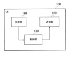
- FIG. 2 is a diagram showing a configuration example of the UE 100. As shown in FIG.
- the UE 100 has a receiver 110, a transmitter 120, and a controller .
- the receiving unit 110 performs various types of reception under the control of the control unit 130.
- Reception section 110 includes an antenna, converts (down-converts) a radio signal received by the antenna into a baseband signal (reception signal), and outputs the baseband signal (reception signal) to control section 130 .
- the transmission unit 120 performs various transmissions under the control of the control unit 130.
- the transmitter 120 includes an antenna, converts (up-converts) a baseband signal (transmission signal) output from the controller 130 into a radio signal, and transmits the radio signal from the antenna.
- the control unit 130 performs various controls in the UE 100.
- Control unit 130 includes at least one memory and at least one processor electrically connected to the memory.
- the memory stores programs executed by the processor and information used for processing by the processor.
- a processor may include a baseband processor and a CPU.
- the baseband processor modulates/demodulates and encodes/decodes the baseband signal.
- the CPU executes programs stored in the memory to perform various processes. Note that the control unit 130 may perform each process and/or each operation in the UE 100 in each embodiment described below.
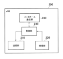
- FIG. 3 is a diagram showing a configuration example of the gNB 200. As shown in FIG.
- the gNB 200 has a transmission section 210, a reception section 220, a control section 230, and a backhaul communication section 240.
- the transmission unit 210 performs various transmissions under the control of the control unit 230.
- Transmitter 210 includes an antenna, converts (up-converts) a baseband signal (transmission signal) output from controller 230 into a radio signal, and transmits the radio signal from the antenna.
- the receiving unit 220 performs various types of reception under the control of the control unit 230.
- Reception section 220 includes an antenna, converts (down-converts) a radio signal received by the antenna into a baseband signal (reception signal), and outputs the baseband signal (reception signal) to control section 230 .
- the control unit 230 performs various controls in the gNB200.
- Control unit 230 includes at least one processor and at least one memory.
- the memory stores programs executed by the processor and information used for processing by the processor.
- a processor may include a baseband processor and a CPU.
- the baseband processor modulates/demodulates and encodes/decodes the baseband signal.
- the CPU executes programs stored in the memory to perform various processes. Note that the control unit 230 may perform each process and/or each operation in the gNB 200 in each embodiment described below.
- the backhaul communication unit 240 is connected to adjacent base stations via the Xn interface.
- the backhaul communication unit 240 is connected to the AMF and UPF 300 via the NG interface.
- the gNB 200 may be composed of a CU (Central Unit) and a DU (Distributed Unit) (that is, functionally divided), and the two units may be connected via an F1 interface.
- FIG. 4 is a diagram showing a configuration example of a protocol stack of a radio interface of a user plane that handles data.
- the user plane radio interface protocol has a physical (PHY) layer, a MAC (Medium Access Control) layer, an RLC (Radio Link Control) layer, a PDCP (Packet Data Convergence Protocol) layer, and an SDAP (Service Data Adaptation Protocol) layer.
- PHY physical
- MAC Medium Access Control
- RLC Radio Link Control
- PDCP Packet Data Convergence Protocol
- SDAP Service Data Adaptation Protocol
- the PHY layer performs encoding/decoding, modulation/demodulation, antenna mapping/demapping, and resource mapping/demapping. Data and control information are transmitted between the PHY layer of the UE 100 and the PHY layer of the gNB 200 via physical channels.
- the MAC layer performs data priority control, hybrid ARQ (HARQ) retransmission processing, random access procedures, and so on. Data and control information are transmitted between the MAC layer of the UE 100 and the MAC layer of the gNB 200 via transport channels.
- the MAC layer of gNB 200 includes a scheduler. The scheduler determines uplink and downlink transport formats (transport block size, modulation and coding scheme (MCS: Modulation and Coding Scheme)) and resource blocks to be allocated to UE 100 .
- MCS modulation and coding scheme
- the RLC layer uses the functions of the MAC layer and PHY layer to transmit data to the RLC layer on the receiving side. Data and control information are transmitted between the RLC layer of the UE 100 and the RLC layer of the gNB 200 via logical channels.
- the PDCP layer performs header compression/decompression and encryption/decryption.
- the SDAP layer maps IP flows, which are units for QoS (Quality of Service) control by the core network, and radio bearers, which are units for QoS control by AS (Access Stratum). Note that SDAP may not be present when the RAN is connected to the EPC.
- FIG. 5 is a diagram showing the configuration of the protocol stack of the radio interface of the control plane that handles signaling (control signals).
- the radio interface protocol stack of the control plane has an RRC (Radio Resource Control) layer and a NAS (Non-Access Stratum) layer instead of the SDAP layer shown in FIG.
- RRC signaling for various settings is transmitted between the RRC layer of the UE 100 and the RRC layer of the gNB 200.
- the RRC layer controls logical, transport and physical channels according to establishment, re-establishment and release of radio bearers.
- RRC connection connection between the RRC of UE 100 and the RRC of gNB 200
- UE 100 is in the RRC connected state.
- RRC connection no connection between RRC of UE 100 and RRC of gNB 200
- UE 100 is in RRC idle state.
- the RRC connection is interrupted (suspended), the UE 100 is in RRC inactive state.
- the NAS layer located above the RRC layer performs session management and mobility management.
- NAS signaling is transmitted between the NAS layer of UE 100 and the NAS layer of AMF 300 .
- the UE 100 has an application layer and the like in addition to the radio interface protocol. [First Embodiment] Next, a first embodiment will be described.
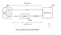
- FIG. 6 is a diagram showing an assumed scenario.
- gNB 200-1 and remote UE 100-1 are scenarios in which communication is performed via relay UE 100-2.
- the remote UE 100-1 performs radio communication (sidelink communication) with the relay UE 100-2 over the PC5 interface (sidelink), which is an interface between UEs.
- the relay UE 100-2 performs radio communication (Uu communication) with the gNB 200-1 over the NR Uu interface.
- Uu communication includes uplink communication and downlink communication.
- FIG. 7 is a diagram showing an example of a user plane protocol stack in an assumed scenario.
- FIG. 7 is also an example of a user plane protocol stack in relaying via the relay UE 100-2 (that is, U2N (UE to Network) relaying).
- U2N UE to Network
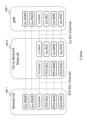
- FIG. 8 shows an example of a control plane protocol stack in an assumed scenario.
- FIG. 8 is also an example of a control plane protocol stack for U2N relaying.
- the gNB 200-1 has a Uu-SRAP (Sidelink Relay Adaptation Protocol) layer, a Uu-RLC layer, a Uu-MAC layer, and a Uu-PHY layer used for communication (Uu communication) on the NR Uu interface.
- Uu-SRAP Segment Relay Adaptation Protocol
- the relay UE 100-2 has a Uu-SRAP layer, a Uu-RLC layer, a Uu-MAC layer, and a Uu-PHY layer used for communication (Uu communication) on the NR Uu interface. Also, the relay UE 100-2 has a PC5-SRAP layer, a PC5-RLC layer, a PC5-MAC layer, and a PC5-PHY layer used for communication on the PC5 interface (PC5 communication).
- the remote UE 100-1 has a Uu-SDAP layer and a Uu-PDCP layer used for communication (Uu) on the Uu interface.
- the remote UE 100-1 also has a PC5-SRAP layer, a PC5-RLC layer, a PC5-MAC layer, and a PC5-PHY layer used for communication on the PC5 interface (PC5 communication).
- the Uu-RRC layer is arranged.
- the SRAP layer is arranged on the Uu interface and the PC5 interface.
- the SRAP layer is an example of a so-called adaptation layer.
- the SRAP layer exists only in layer 2 relays and not in layer 3 relays.
- the SRAP layer exists in all of the remote UE 100-1, the relay UE 100-2, and the gNB 200-1.
- PC5-SRAP and Uu-SRAP have a bearer mapping function. For example, it has the following bearer mapping function.
- the Uu-SRAPs of the remote UE 100-1 and gNB 200-1 perform mapping between bearers (Uu-PDCP) and PC5 RLC channels (PC5-RLC). Also, the PC5-SRAP and Uu-SRAP of the relay UE 100-2 perform mapping between the PC5 RLC channel (PC5-RLC) and the Uu RLC channel (Uu-RLC). Furthermore, Uu-SRAP has the function of identifying the remote UE 100-1.
- each of the remote UE 100-1 and relay UE 100-2 may have an RRC layer for PC5.
- RRC layer is called "PC5-RRC layer”.
- PC5-RRC layer There is a one-to-one correspondence between the PC5-RRC connection and the PC5 unicast link between the remote UE 100-1 and the relay UE 100-2, and the PC5-RRC connection is established after the PC5 unicast link is established.
- each of the remote UE 100-1 and the relay UE 100-2 may have a PC5-S (Signaling) protocol layer.
- the PC5-S protocol layer is a layer above the PDCP layer.
- the PC5-S protocol layer is also a layer for transmitting control information, like the PC5-RRC layer.
- Multipath U2N sidelink relaying is relaying (communication) where one path is a direct link (ie Uu) and the other path is an indirect link (ie U2N sidelink relaying).
- a direct link is a link between a network (eg, a gNB) and remote UE 100-1 that does not go through relay UE 100-2.
- an indirect link is a link between the network and the remote UE 100-1 via the relay UE 100-2.
- split bearers include DC (Dual Connectivity) split bearers and MBS (Multicast and Broadcast Service) split bearers.
- DC split bearer When the DC split bearer is set, the PDCP entity is associated with the RLC entity of the MCG (Master Cell Group) and the RLC entity of the SCG (Secondary Cell Group).
- MBS Multicast and Broadcast Service
- the PDCP entity When a split bearer by MBS is set, the PDCP entity is linked to the RLC entity for PTM (Point-to-Multipoint) and the RLC entity for PTP (Point-to-Point).
- PTM Point-to-Multipoint
- PTP Point-to-Point
- multi-link split bearer is, for example, a split bearer composed of direct links and indirect links.
- priorities are defined between UL transmission (direct link) and sidelink relay (indirect link). Therefore, for example, it is not assumed that the remote UE 100-1 performs UL transmission and sidelink relay at the same time.
- the "multilink split bearer” allows the remote UE 100-1 to transmit the same data using two links or to transmit different data using two links.
- the “multilink split bearer” allows the remote UE 100-1 to use one link for the Control Plane (CP) and the other link for the User Plane (UP). In this way, the "multilink split bearer" makes it possible to support various operations.
- Multilink split bearer can be applied to various forms of sidelink relay.
- FIG. 9 shows a configuration example of the mobile communication system 1 when "multilink split bearer" is applied to intra-cell sidelink relay.
- Such a “multi-link split bearer” is called an "intra-cell U2N multi-link split bearer”.
- FIG. 10 shows a configuration example of the mobile communication system 1 when a "multilink split bearer" is applied to inter-cell sidelink relay.
- a "multi-link split bearer” is called an "inter-cell U2N multi-link split bearer”.
- FIG. 11 shows a configuration example of the mobile communication system 1 when "multilink split bearer" is applied to sidelink relay between gNBs (Inter-gNB).
- Such a "multi-link split bearer” is called an "Inter-gNB U2N multi-link split bearer”.
- FIG. 12 shows a configuration example of the mobile communication system 1 when "multilink split bearer" is applied to two indirect links set between the network and the remote UE 100-1.
- Such a “multi-link split bearer” is called a “multi-relay U2N multi-link split bearer”.
- FIG. 13 shows a configuration example of the mobile communication system 1 when "multilink split bearer" is applied to U2U (UE to UE) sidelink relay.
- Such a "multi-link split bearer” is called a "U2U multi-link split bearer”.
- the first embodiment is an embodiment applicable to each form of the multilink split bearer set in this way.
- the other link (direct link in FIGS. 9-11 and 13, one indirect link in FIG. 12) may be available.
- the remote UE 100-1 (or the second remote UE 100-12) detects an abnormality in the PC5 link
- an example of transmitting an abnormality notification message to the gNB 200-1 (or the first remote UE 100-11) via the other link will be described.
- the first remote user equipment detects an indirect link failure.
- the first remote user device sends an anomaly notification message containing information indicating the anomaly to a predetermined device (eg, gNB 200-1 or second remote UE 100-12) via a predetermined link (eg, another link different from the indirect link).
- a predetermined device eg, gNB 200-1 or second remote UE 100-12
- the gNB 200-1 (or the second remote UE 100-12) can grasp the abnormality of the PC5 link. Then, the gNB 200-1 can perform various processes such as data transmission stop for the abnormality.
- the first embodiment is applicable to a mobile communication system (for example, mobile communication system 1) in which first communication on a predetermined link between a first remote user device and a predetermined device and second communication on an indirect link between the first remote user device and the predetermined device via a second relay user device are possible.
- a mobile communication system for example, mobile communication system 1
- first communication on a predetermined link between a first remote user device and a predetermined device and second communication on an indirect link between the first remote user device and the predetermined device via a second relay user device are possible.
- the first remote user equipment is, for example, the remote UE 100-1 or the first remote UE 100-11.
- the predetermined device is, for example, the gNB 200-1 or the second remote UE 100-12.
- a predetermined link is, for example, an indirect link or a direct link.
- the second relay user equipment is, for example, the relay UE 100-2 or the second relay UE 100-22.
- FIG. 14 is a diagram showing an operation example according to the first embodiment.
- FIG. 14 shows an operation example when the "intracell U2N multilink split bearer" (FIG. 9) is set as the split bearer.
- a direct link is established between the remote UE 100-1 and gNB 200-1 (step S10).
- an indirect link is established between the remote UE 100-1 and the gNB 200-1 via the relay UE 100-2 (step S11).
- a multilink split bearer ie, “intracell U2N multilink split bearer” is configured on the direct and indirect links.
- the remote UE 100-1 detects Radio Link Failure (RLF) (PC5 RLF) in the PC5 link with the relay UE 100-2.
- RLF Radio Link Failure
- PC5 RLF Radio Link Failure
- a timer may be started, and a radio link failure may be detected when the timer expires without detecting an in-sync state for a second predetermined number of consecutive times.
- the remote UE 100-1 may detect a radio link failure when the number of retransmissions of packets from the remote UE 100-1 to the relay UE 100-2 reaches the maximum value.
- the remote UE 100-1 may detect an abnormality (Uu RLF) on the Uu link side.
- Uu RLF abnormality
- the remote UE 100-1 detects an abnormality in the Uu link, it transmits an abnormality notification message to the gNB 200-1 via the relay UE 100-2.
- the anomaly notification message may include information indicating that the anomaly has occurred in Uu.
- the remote UE 100-1 sends an anomaly notification message to the gNB 200-1 via the direct link.
- the anomaly notification message may include information indicating an anomaly of the PC5 link.
- the anomaly notification message may include information indicating that PC5 RLF has occurred.
- the anomaly notification message may include the identification information (UE ID, L2 ID, or L2 Destination ID) of the relay UE 100-2, which is the other party of the anomaly.
- the anomaly notification message may be sent as an RRC message.
- the first remote UE 100-11 uses the direct link (PC5) to send an anomaly notification message to the second remote UE 100-12.
- the anomaly notification message may be sent as a PC5-RRC message.
- the remote UE 100-1 transmits an abnormality notification message via the first relay UE 100-21 (for example, the first relay user apparatus) in response to an abnormality in the PC5 link with the second relay UE 100-22 (for example, the second relay user apparatus).
- the failure notification message may be sent as a PC5-RRC message on the PC5 link and as an RRC message on the Uu link.
- step S14 the gNB 200-1 performs processing such as stopping communication to the indirect link in response to receiving the anomaly notification message.
- the second remote UE 100-12 performs processing such as stopping communication on the indirect link in response to receiving the anomaly notification message.
- the split bearer shown in FIG. 14 is the "inter gNB U2N multilink split bearer" (FIG. 11)
- the first gNB 200-1 (MN) in response to receiving the anomaly notification message, transmits a message including information indicating communication stop for the indirect link to the second gNB 200-2 (SN) using the Xn interface.
- the second gNB 200-2 performs processing such as communication stop for the indirect link.
- the first embodiment is applicable to all forms of multi-split bearers described above (FIGS. 9-13).
- the remote UE 100-1 sends an anomaly notification message to the gNB 200-1 (FIGS. 9 to 12), and the first remote UE 100-11 sends an anomaly notification message to the second remote UE 100-12 (or the second remote user device) (FIG. 13).
- an anomaly notification message is transmitted via an indirect link (an indirect link via the first relay UE 100-21). Otherwise, including the latter, anomaly notification messages are sent via the direct link.
- the second embodiment is an example of notifying the remote UE 100-1 (or the relay UE 100-2) when the relay UE 100-2 (or the remote UE 100-1) performs handover.
- a first handover notification message including information indicating the handover is transmitted to the first remote user equipment (for example, the remote UE 100-1) via the indirect link
- the second handover notification message including information indicating the handover is sent to the indirect link. to the second relay user equipment via.
- the remote UE 100-1 receives the handover notification message, so processing such as canceling the split bearer setting for the relay UE 100-2 becomes possible. Therefore, the remote UE 100-1 can properly communicate with the gNB 200-1. Also, even when the remote UE 100-1 is handed over, the relay UE 100-2 similarly receives the handover notification message, so processing such as canceling the split bearer setting for the remote UE 100-1 is possible, and communication with the gNB 200-1 can be performed appropriately.
- FIG. 15 is a diagram showing an operation example according to the second embodiment.
- FIG. 15 shows an operation example when the “intracell U2N multilink split bearer” (FIG. 9) is set as the split bearer.
- a direct link is established between the remote UE 100-1 and gNB 200-1 (step S20), and an indirect link is established between the remote UE 100-1 and gNB 200-1 via the relay UE 100-2 (step S21).
- a multilink split bearer ie, “intracell U2N multilink split bearer” is configured on the direct and indirect links.
- step S22 the relay UE 100-2 performs handover to another gNB different from the gNB 200-1.
- the other gNB may not support split bearers.
- the relay UE 100-2 transmits a handover notification message (or first handover message) including information indicating the handover to the remote UE 100-1 via the indirect link.
- the handover notification message may be sent as a PC5-RRC message.
- the handover notification message enables the remote UE 100-1 to grasp that the relay UE 100-2 has performed handover.
- step S24 the remote UE 100-1 cancels the split bearer setting for the relay UE 100-2 or stops data transmission to the relay UE 100-2 in response to receiving the handover notification message.
- the remote UE 100-1 when the remote UE 100-1 is handed over to another gNB, the remote UE 100-1 transmits a handover notification message (or second handover message) including information indicating the handover to the relay UE 100-2 via the indirect link.
- the relay UE 100-2 Upon receiving the handover notification message, the relay UE 100-2 cancels the split bearer setting and stops data transmission to the remote UE 100-1.
- the second embodiment is applicable to split bearer forms (FIGS. 9 to 12) other than the "U2U multilink split bearer" (FIG. 13).
- multi-relay U2N multi-link split bearer (FIG. 12)
- the second relay UE 100-22 transmits a handover notification message to the remote UE 100-1.
- the remote UE 100-1 performs processing such as canceling the split bearer setting.
- the remote UE 100-1 transmits a handover notification message to the second relay UE 100-22 (or the first relay UE 100-21).
- the second relay UE 100-22 (or the first relay UE 100-21) performs processing such as canceling the split bearer setting.
- the third embodiment is an example of notifying the gNB 200-1 (or the second remote UE 100-12) when the remote UE 100-1 (or the first remote UE 100-11) performs relay reselection.
- the first remote user equipment executes the relay station reselection process.
- the first remote user equipment transmits a relay station reselection notification message including identification information of the third relay user equipment selected by the relay station reselection process to a predetermined device (eg, gNB 200-1 or second remote UE 100-12) via a predetermined link (eg, direct link or indirect link).
- a predetermined device eg, gNB 200-1 or second remote UE 100-12
- a predetermined link eg, direct link or indirect link.
- the gNB 200-1 (or the second remote UE 100-12) can grasp that the relay station reselection has been performed by the remote UE 100-1 (or the first remote UE 100-11), so it is possible to set a split bearer for the new relay UE reselected by the relay station reselection. Thereby, it is possible to appropriately perform communication in the mobile communication system 1 .
- FIG. 16 is a diagram showing an operation example according to the third embodiment.
- FIG. 16 shows an operation example when the "intracell U2N multilink split bearer" (FIG. 9) is set as the split bearer.
- a direct link is established between the remote UE 100-1 and gNB 200-1 (step S30), and an indirect link is established between the remote UE 100-1 and gNB 200-1 via the relay UE 100-2 (step S31).
- a multilink split bearer ie, “intracell U2N multilink split bearer” is configured on the direct and indirect links.
- step S32 the remote UE 100-1 performs relay reselection.
- Relay station reselection is performed, for example, so that UE 100 in the RRC idle state or RRC inactive state moves from the current relay UE (eg, relay UE #1) to another relay UE (eg, relay UE #2) as it moves.
- relay station reselection for example, the following processing is performed.
- the remote UE 100-1 may perform relay station reselection when the frequency used for sidelink communication is out of the coverage range. Also, the remote UE 100-1 may perform relay station reselection when the RSRP measurement value of the cell in which it camps on becomes lower than a predetermined threshold. The remote UE 100-1 selects a relay UE whose SD-RSRP (Sidelink Discovery Reference Signal Received Power) exceeds the minimum received RSRP level (minimum received quality level) as a candidate relay UE.
- SD-RSRP Systemlink Discovery Reference Signal Received Power
- the remote UE 100-1 selects the candidate relay UE with the highest radio link (i.e., PC5 unicast link) quality among all the candidate relay UEs that satisfy the predetermined criteria as the relay UE for reselection (e.g., the third relay user equipment). The remote UE 100-1 then reselects the relay UE and camps on the relay UE.
- the candidate relay UE with the highest radio link i.e., PC5 unicast link
- step S33 the remote UE 100-1 sends a relay station reselection notification message to the gNB 200-1 via the direct link.
- This message includes the identification information (UE ID, L2 ID, or L2 Destination ID) of the relay UE reselected by the remote UE 100-1 through relay station reselection.
- the message may include information indicating that the relay station reselection was successful.
- the message may be sent as an RRC message.
- the first remote UE 100-11 performs relay station reselection (step S32) and transmits a relay station reselection notification message to the second remote UE 100-12 via the direct link (step S33).
- the gNB 200-1 that has received the message may, if necessary, update (or change) the split bearer setting to the split bearer via the reselected relay UE (eg, "intracell U2N multilink split bearer").
- the remote UE 100-1 also transmits a relay station reselection notification message when even one relay UE could not be reselected due to relay station reselection (step S33).
- the message may include information indicating that even one relay UE could not be reselected due to relay station reselection. Since the message does not include the identification information of the reselected relay UE, the gNB 200-1 that received the message does not include the identification information, so the remote UE 100-1 reselects the relay UE. It may be understood that it was not possible.
- the gNB 200-1 that received the message deletes the split bearer configuration (de-configure) as necessary.
- the third embodiment can also be applied to all the forms of multi-split bearers described above (FIGS. 9 to 13).
- the remote UE 100-1 transmits the relay station reselection notification message to the gNB 200-1 (FIGS. 9 to 12)
- the first remote UE 100-11 transmits the relay station reselection notification message to the second remote UE 100-12 (FIG. 13).
- the 'multi-relay U2N multi-link split bearer' (Fig. 12) transmits the relay station reselection notification message via the indirect link. Otherwise, including the latter, the relay reselection notification message is sent via the direct link.
- the fourth embodiment is an embodiment regarding what kind of processing is performed under what conditions when one link of the split bearer becomes a radio link failure (RLF).
- RLF radio link failure
- the first remote user equipment detects a radio link failure on the indirect link.
- the first remote user equipment does not perform relay reselection if the radio quality of a given link (eg direct link or indirect link) is above a threshold.
- the remote UE 100-1 will not detect PC5 RLF and unconditionally reselect the relay station, and if the radio quality of one link is equal to or higher than the threshold, the remote UE 100-1 will be able to communicate using that link. Therefore, appropriate communication can be performed in the mobile communication system 1 .
- the first remote user equipment when it detects a radio link failure, it starts a timer, and if the timer expires without recovering from the radio link failure on the indirect link, it deletes the split bearer setting set for the direct link and the indirect link.
- the remote UE 100-1 waits for recovery from the PC5 RLF until a predetermined period of time has passed even if the PC5 RLF occurs, and if it still does not recover, the split bearer setting is deleted. Therefore, split bearers can be set appropriately.
- FIG. 17 is a diagram showing an operation example according to the fourth embodiment.
- FIG. 17 also shows an operation example when the “intracell U2N multilink split bearer” (FIG. 9) is set as the split bearer.
- a direct link is established between the remote UE 100-1 and gNB 200-1 (step S40), and an indirect link is established between the remote UE 100-1 and gNB 200-1 via the relay UE 100-2 (step S41).
- a multilink split bearer ie, “intracell U2N multilink split bearer” is configured on the direct and indirect links.
- the remote UE 100-1 detects a radio link failure (PC5 RLF) on the indirect link.
- PC5 RLF radio link failure
- step S43 the remote UE 100-1 starts counting a timer in response to detection of the PC5 RLF.
- the remote UE 100-1 checks the radio quality of the direct link.
- the radio quality may be SL-RSRP (Sidelink Reference Signal Received Power), SD-RSRP (Sidelink Discovery Reference Signal Received Power), or Uu RSRP.
- the remote UE 100-1 does not perform relay reselection when the direct link radio quality is equal to or higher than the threshold.
- the remote UE 100-1 is able to communicate via a direct link.
- the remote UE 100-1 performs relay station reselection when the radio quality of the direct link is below the threshold.
- the remote UE 100-1 is to ensure communication with the gNB 200-1 via the relay UE reselected by the relay station reselection.
- the threshold may be set from the gNB 200-1.
- the split bearer is a "multi-relay U2N multilink split bearer" (FIG. 12)
- the remote UE 100-1 when the remote UE 100-1 detects PC5 RLF on the indirect link to the second relay UE 100-22, it will check the radio quality of the indirect link to the first relay UE 100-21. Also in this case, the remote UE 100-1 may not perform relay station reselection when the radio quality is equal to or higher than the threshold, and may perform relay station reselection when the radio quality is less than the threshold. Alternatively, the remote UE 100-1 may perform relay station reselection when PC5 RLF is detected for all indirect links. In this case, the remote UE 100-1 may not perform relay station reselection when PC5 RLF is not detected on all indirect links (for example, when PC5 RLF is detected on one indirect link).
- step S45 the remote UE 100-1 stops counting the timer when recovering from the PC5 RLF (returning to normal).
- step S46 the remote UE 100-1 discards the split bearer setting if the timer expires without recovery from the PC5 RLF. Alternatively, if the timer expires without recovery from the PC5 RLF, the remote UE 100-1 may delete the setting of the link in which the radio link failure has occurred from the setting of the split bearer.
- the fourth embodiment can also be applied to all the forms of multi-split bearers described above (FIGS. 9 to 13).
- the remote UE 100-1 is opposite the gNB 200-1 (FIGS. 9 to 12) and a first remote UE 100-11 is opposite the second remote UE 100-12 (FIG. 13).
- the former furthermore, there are cases where split bearers are set with a direct link and an indirect link (FIGS. 9 to 11) and cases where a split bearer is set with two indirect links (FIG. 12). In the latter, split bearers are set for direct and indirect links.
- a program that causes a computer to execute each process performed by the UE 100 (including the relay UE 100-2 and the remote UE 100-1) or the gNB 200 may be provided.
- the program may be recorded on a computer readable medium.
- a computer readable medium allows the installation of the program on the computer.
- the computer-readable medium on which the program is recorded may be a non-transitory recording medium.
- the non-transitory recording medium is not particularly limited, but may be, for example, a recording medium such as CD-ROM or DVD-ROM.
- circuits that execute each process performed by the UE 100 or the gNB 200 may be integrated, and at least part of the UE 100 or the gNB 200 may be configured as a semiconductor integrated circuit (chipset, SoC: System on a chip).
- chipsset, SoC System on a chip
- a communication control method in a mobile communication system capable of first communication on a predetermined link between a first remote user device and a predetermined device and second communication on an indirect link between the first remote user device and the predetermined device via a second relay user device, comprising: detecting, by the first remote user device, an abnormality in the indirect link; said first remote user device sending an anomaly notification message including information indicating said anomaly to said predetermined device via said predetermined link.
- a communication control method in a mobile communication system capable of first communication on a predetermined link between a first remote user equipment and a base station and second communication on an indirect link between the first remote user equipment and the base station via a second relay user equipment, comprising: when the second relay user equipment has handed over to another base station, sending a first handover notification message including information indicating the handover to the first remote user equipment via the indirect link; and transmitting a second handover notification message including information indicating the handover to the second relay user equipment via the indirect link when the first remote user equipment has handed over to the other base station.
- a communication control method in a mobile communication system capable of first communication on a predetermined link between a first remote user device and a predetermined device and second communication on an indirect link between the first remote user device and the predetermined device via a second relay user device, comprising: said first remote user equipment performing a relay station reselection process; said first remote user equipment transmitting a relay station reselection notification message including identification information of a third relay user equipment selected by said relay station reselection process to said predetermined device via said predetermined link.
- a communication control method in a mobile communication system capable of first communication on a predetermined link between a first remote user device and a predetermined device and second communication on an indirect link between the first remote user device and the predetermined device via a second relay user device, comprising: said first remote user equipment detecting a radio link failure on said indirect link; said first remote user equipment not performing relay reselection if the radio quality of said predetermined link is equal to or greater than a threshold.
- the step of not performing relay station reselection includes the first remote user equipment performing the relay station reselection if the radio quality of the given link is below the threshold;
- the first remote user equipment starts a timer when it detects the radio link failure, and if the timer expires without recovery from the radio link failure on the indirect link, deleting the split bearer configuration set on the predetermined link and the indirect link.
- the predetermined device is a base station, said predetermined link is either a direct link between said first remote user device and said predetermined device, or said predetermined link is an indirect link between said first remote user device and said predetermined device via a first relay user device;
- the communication control method according to any one of (1) to (4) above.
- the predetermined device is a second remote user device, said predetermined link is a direct link between said first remote user device and said predetermined device;
- said predetermined link is either a direct link between said first remote user equipment and said base station, or said predetermined link is an indirect link between said first remote user equipment and said base station via a first relay user equipment;
Landscapes
- Engineering & Computer Science (AREA)
- Computer Networks & Wireless Communication (AREA)
- Signal Processing (AREA)
- Mobile Radio Communication Systems (AREA)
Abstract
Un procédé de commande de communication selon un aspect est un procédé de commande de communication dans un système de communication mobile qui peut mettre en œuvre une première communication entre un premier UE distant et un dispositif prescrit sur une liaison prescrite, ainsi qu'une seconde communication entre le premier UE distant et le dispositif prescrit par l'intermédiaire d'un second UE relais sur une liaison indirecte. Le procédé de commande de communication consiste à détecter, par l'intermédiaire du premier UE distant, d'une anomalie sur la liaison indirecte. De plus, le procédé de commande de communication consiste à transmettre, par l'intermédiaire du premier UE distant, un message de notification d'anomalie comprenant des informations indiquant l'anomalie au dispositif prescrit par l'intermédiaire de la liaison prescrite.
Applications Claiming Priority (2)
| Application Number | Priority Date | Filing Date | Title |
|---|---|---|---|
| US202263301786P | 2022-01-21 | 2022-01-21 | |
| US63/301,786 | 2022-01-21 |
Publications (1)
| Publication Number | Publication Date |
|---|---|
| WO2023140334A1 true WO2023140334A1 (fr) | 2023-07-27 |
Family
ID=87348391
Family Applications (1)
| Application Number | Title | Priority Date | Filing Date |
|---|---|---|---|
| PCT/JP2023/001570 WO2023140334A1 (fr) | 2022-01-21 | 2023-01-19 | Procédé de commande de communication |
Country Status (1)
| Country | Link |
|---|---|
| WO (1) | WO2023140334A1 (fr) |
Citations (1)
| Publication number | Priority date | Publication date | Assignee | Title |
|---|---|---|---|---|
| WO2018030007A1 (fr) * | 2016-08-08 | 2018-02-15 | ソニー株式会社 | Dispositif et procédé de communication |
-
2023
- 2023-01-19 WO PCT/JP2023/001570 patent/WO2023140334A1/fr unknown
Patent Citations (1)
| Publication number | Priority date | Publication date | Assignee | Title |
|---|---|---|---|---|
| WO2018030007A1 (fr) * | 2016-08-08 | 2018-02-15 | ソニー株式会社 | Dispositif et procédé de communication |
Non-Patent Citations (1)
| Title |
|---|
| HUAWEI, HISILICON: "Discussion on service continuity for L2 UE to NW Relay", 3GPP DRAFT; R2-2201511, 3RD GENERATION PARTNERSHIP PROJECT (3GPP), 11 January 2022 (2022-01-11), XP052094609 * |
Similar Documents
| Publication | Publication Date | Title |
|---|---|---|
| US10039086B2 (en) | Communication method and apparatus in network environment where terminal may have dual connectivity to multiple base stations | |
| WO2020032129A1 (fr) | Dispositif de relais | |
| JP7291763B2 (ja) | 通信制御方法 | |
| KR20150055535A (ko) | 단말이 복수의 기지국에 이중으로 연결될 수 있는 네트워크 환경에서의 통신 방법 및 장치 | |
| JP7413507B2 (ja) | 通信制御方法 | |
| JP7212204B2 (ja) | 通信制御方法 | |
| JP7212199B2 (ja) | 通信制御方法 | |
| JP7322230B2 (ja) | 通信制御方法 | |
| US20230078657A1 (en) | Communication control method | |
| JP2022141908A (ja) | 通信制御方法 | |
| US20220201786A1 (en) | Methods and apparatus to reduce packet latency in multi-leg transmission | |
| JP2024020471A (ja) | 通信制御方法、遠隔ユーザ装置、及びプロセッサ | |
| US20230328629A1 (en) | Communication control method | |
| US20230080014A1 (en) | Communication control method | |
| US20230328607A1 (en) | Communication control method | |
| US20230091236A1 (en) | Communication control method and user equipment | |
| WO2023140334A1 (fr) | Procédé de commande de communication | |
| WO2023140333A1 (fr) | Procédé de commande de communication | |
| WO2023140332A1 (fr) | Procédé de commande de communication | |
| WO2024090357A1 (fr) | Procédé de commande de communication et dispositif réseau | |
| WO2023013604A1 (fr) | Procédé de commande de communication | |
| WO2023286689A1 (fr) | Procédé de commande de communication | |
| WO2023002987A1 (fr) | Procédé de commande de communication | |
| JP7050721B2 (ja) | 無線通信装置及び制御方法 | |
| JP7426383B2 (ja) | 通信制御方法 |
Legal Events
| Date | Code | Title | Description |
|---|---|---|---|
| 121 | Ep: the epo has been informed by wipo that ep was designated in this application |
Ref document number: 23743326 Country of ref document: EP Kind code of ref document: A1 |