WO2023140332A1 - Procédé de commande de communication - Google Patents
Procédé de commande de communication Download PDFInfo
- Publication number
- WO2023140332A1 WO2023140332A1 PCT/JP2023/001567 JP2023001567W WO2023140332A1 WO 2023140332 A1 WO2023140332 A1 WO 2023140332A1 JP 2023001567 W JP2023001567 W JP 2023001567W WO 2023140332 A1 WO2023140332 A1 WO 2023140332A1
- Authority
- WO
- WIPO (PCT)
- Prior art keywords
- user equipment
- link
- base station
- remote user
- remote
- Prior art date
Links
Images


Classifications
-
- H—ELECTRICITY
- H04—ELECTRIC COMMUNICATION TECHNIQUE
- H04W—WIRELESS COMMUNICATION NETWORKS
- H04W72/00—Local resource management
- H04W72/04—Wireless resource allocation
- H04W72/044—Wireless resource allocation based on the type of the allocated resource
- H04W72/0457—Variable allocation of band or rate
-
- H—ELECTRICITY
- H04—ELECTRIC COMMUNICATION TECHNIQUE
- H04W—WIRELESS COMMUNICATION NETWORKS
- H04W80/00—Wireless network protocols or protocol adaptations to wireless operation
- H04W80/02—Data link layer protocols
-
- H—ELECTRICITY
- H04—ELECTRIC COMMUNICATION TECHNIQUE
- H04W—WIRELESS COMMUNICATION NETWORKS
- H04W88/00—Devices specially adapted for wireless communication networks, e.g. terminals, base stations or access point devices
- H04W88/02—Terminal devices
- H04W88/04—Terminal devices adapted for relaying to or from another terminal or user
-
- H—ELECTRICITY
- H04—ELECTRIC COMMUNICATION TECHNIQUE
- H04W—WIRELESS COMMUNICATION NETWORKS
- H04W92/00—Interfaces specially adapted for wireless communication networks
- H04W92/16—Interfaces between hierarchically similar devices
- H04W92/18—Interfaces between hierarchically similar devices between terminal devices
Definitions
- the present disclosure relates to a communication control method used in mobile communication systems.
- sidelink relay technology using user equipment as a relay node is under consideration (see, for example, "3GPP TS 38.300 V16.8.0 (2021-12)").
- Sidelink relaying is a technology in which a relay node called a relay user equipment (Relay UE) intervenes in communication between a base station and a remote user equipment (Remote UE) and relays this communication.
- Relay UE relay user equipment
- a communication control method is a communication control method in a mobile communication system in which first communication on a direct link between a remote user equipment and a base station and second communication on an indirect link between the remote user equipment and a base station via a relay user equipment are possible.
- the communication control method comprises the step of the base station sending to the remote user equipment binding information binding the PDCP entity to the RLC entity of the direct link and the SRAP entity of the indirect link.
- the communication control method also includes the step of binding the PDCP entity to the RLC entity and the SRAP entity according to the binding information by the remote user equipment.
- a communication control method is a communication control method in a mobile communication system in which first communication on a direct link between a remote user equipment and a base station and second communication on an indirect link between the remote user equipment and a base station via a relay user equipment are possible.
- the communication control method comprises the step of the base station sending to the remote user equipment binding information binding the PDCP entity to the first RLC entity of the direct link and the second RLC entity of the indirect link.
- the communication control method comprises the step of the remote user equipment configuring an SRAP entity that links the PDCP entity to the first RLC entity and the second RLC entity according to the linking information.
- a communication control method is a communication control method in a mobile communication system in which first communication on a direct link between a remote user equipment and a base station and second communication on an indirect link between the remote user equipment and a base station via a relay user equipment are possible.
- the communication control method comprises the step of the base station transmitting activation indication information to the remote user equipment to indicate activation or deactivation of the direct link and activation or deactivation of the indirect link.
- the communication control method also includes the remote user equipment activating or deactivating the direct link and activating or deactivating the indirect link according to the activation indication information.
- FIG. 1 is a diagram showing a configuration example of a mobile communication system according to the first embodiment.
- FIG. 2 is a diagram showing a configuration example of a UE according to the first embodiment.
- FIG. 3 is a diagram showing a configuration example of a gNB according to the first embodiment.
- FIG. 4 is a diagram showing a configuration example of a user plane protocol stack according to the first embodiment.
- FIG. 5 is a diagram showing a configuration example of a protocol stack of the control plane according to the first embodiment.
- FIG. 6 is a diagram showing an assumed scenario according to the first embodiment.
- FIG. 7 is a diagram showing a configuration example of a user plane protocol stack in an assumed scenario according to the first embodiment.
- FIG. 8 is a diagram showing a configuration example of a protocol stack of a control plane in an assumed scenario according to the first embodiment.
- FIG. 9 is a diagram showing a configuration example of a mobile communication system according to the first embodiment.
- FIG. 10 is a diagram showing a configuration example of a protocol stack according to the first embodiment.
- FIG. 11 is a diagram showing an operation example according to the first embodiment.
- FIG. 12 is a diagram showing an operation example according to the first embodiment.
- FIG. 13 is a diagram showing a configuration example of a protocol stack according to a modification of the first embodiment.
- FIG. 14 is a diagram showing an operation example according to the second embodiment.
- FIG. 15 is a diagram showing a configuration example of a mobile communication system according to the third embodiment.
- FIG. 16 is a diagram showing a configuration example of a mobile communication system according to the fourth embodiment.
- FIG. 17 is a diagram showing an operation example according to the fourth embodiment.
- FIG. 18 is a diagram showing an operation example according
- a mobile communication system 1 is a 3GPP 5G system.
- the radio access scheme in the mobile communication system 1 is NR (New Radio), which is a 5G radio access scheme.
- NR New Radio
- LTE Long Term Evolution
- 6G future mobile communication systems such as 6G may also be applied to the mobile communication system 1 .
- FIG. 1 is a diagram showing a configuration example of a mobile communication system 1 according to one embodiment.
- the mobile communication system 1 includes a user equipment (UE) 100, a 5G radio access network (NG-RAN: Next Generation Radio Access Network) 10, and a 5G core network (5GC: 5G Core Network) 20.
- UE user equipment
- NG-RAN Next Generation Radio Access Network
- 5GC 5G Core Network
- the UE 100 is a mobile wireless communication device.
- the UE 100 may be any device as long as it is used by the user.
- the UE 100 is a mobile phone terminal (including a smartphone), a tablet terminal, a notebook PC, a communication module (including a communication card or chipset), a sensor or a device provided in a sensor, a vehicle or a device provided in the vehicle (Vehicle UE), an aircraft or a device provided in the aircraft (Aerial UE).
- the NG-RAN 10 includes a base station (called "gNB” in the 5G system) 200.
- the gNBs 200 are interconnected via an Xn interface, which is an interface between base stations.
- the gNB 200 manages one or more cells.
- the gNB 200 performs radio communication with the UE 100 that has established connection with its own cell.
- the gNB 200 has a radio resource management (RRM) function, a user data (hereinafter simply referred to as “data”) routing function, a measurement control function for mobility control/scheduling, and the like.
- RRM radio resource management
- a “cell” is used as a term indicating the minimum unit of a wireless communication area.
- a “cell” is also used as a term indicating a function or resource for radio communication with the UE 100 .
- One cell belongs to one carrier frequency.
- a "cell" and a base station may be used without distinguishing.
- the gNB 200 can also be connected to the EPC (Evolved Packet Core), which is the LTE core network.
- EPC Evolved Packet Core
- LTE base stations can also connect to 5GC20.
- An LTE base station and the gNB 200 can also be connected via an interface between base stations.
- 5GC20 includes AMF (Access and Mobility Management Function) and UPF (User Plane Function) 300.
- AMF performs various mobility control etc. with respect to UE100.
- AMF manages the mobility of UE 100 by communicating with UE 100 using NAS (Non-Access Stratum) signaling.
- the UPF controls data transfer.
- AMF and UPF 300 are connected to gNB 200 via an NG interface, which is a base station-core network interface.
- FIG. 2 is a diagram showing a configuration example of the UE 100. As shown in FIG.
- the UE 100 has a receiver 110, a transmitter 120, and a controller .
- the receiving unit 110 performs various types of reception under the control of the control unit 130.
- Reception section 110 includes an antenna, converts (down-converts) a radio signal received by the antenna into a baseband signal (reception signal), and outputs the baseband signal (reception signal) to control section 130 .
- the transmission unit 120 performs various transmissions under the control of the control unit 130.
- the transmitter 120 includes an antenna, converts (up-converts) a baseband signal (transmission signal) output from the controller 130 into a radio signal, and transmits the radio signal from the antenna.
- the control unit 130 performs various controls in the UE 100.
- Control unit 130 includes at least one memory and at least one processor electrically connected to the memory.
- the memory stores programs executed by the processor and information used for processing by the processor.
- a processor may include a baseband processor and a CPU.
- the baseband processor modulates/demodulates and encodes/decodes the baseband signal.
- the CPU executes programs stored in the memory to perform various processes. Note that the control unit 130 may perform each process and/or each operation in the UE 100 in each embodiment described below.
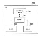
- FIG. 3 is a diagram showing a configuration example of the gNB 200. As shown in FIG.
- the gNB 200 has a transmission section 210, a reception section 220, a control section 230, and a backhaul communication section 240.
- the transmission unit 210 performs various transmissions under the control of the control unit 230.
- Transmitter 210 includes an antenna, converts (up-converts) a baseband signal (transmission signal) output from controller 230 into a radio signal, and transmits the radio signal from the antenna.
- the receiving unit 220 performs various types of reception under the control of the control unit 230.
- Reception section 220 includes an antenna, converts (down-converts) a radio signal received by the antenna into a baseband signal (reception signal), and outputs the baseband signal (reception signal) to control section 230 .
- the control unit 230 performs various controls in the gNB200.
- Control unit 230 includes at least one processor and at least one memory.
- the memory stores programs executed by the processor and information used for processing by the processor.
- a processor may include a baseband processor and a CPU.
- the baseband processor modulates/demodulates and encodes/decodes the baseband signal.
- the CPU executes programs stored in the memory to perform various processes. Note that the control unit 230 may perform each process and/or each operation in the gNB 200 in each embodiment described below.
- the backhaul communication unit 240 is connected to adjacent base stations via the Xn interface.
- the backhaul communication unit 240 is connected to the AMF and UPF 300 via the NG interface.
- the gNB 200 may be composed of a CU (Central Unit) and a DU (Distributed Unit) (that is, functionally divided), and the two units may be connected via an F1 interface.
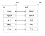
- FIG. 4 is a diagram showing a configuration example of a protocol stack of a radio interface of a user plane that handles data.
- the user plane radio interface protocol has a physical (PHY) layer, a MAC (Medium Access Control) layer, an RLC (Radio Link Control) layer, a PDCP (Packet Data Convergence Protocol) layer, and an SDAP (Service Data Adaptation Protocol) layer.
- PHY physical
- MAC Medium Access Control
- RLC Radio Link Control
- PDCP Packet Data Convergence Protocol
- SDAP Service Data Adaptation Protocol
- the PHY layer performs encoding/decoding, modulation/demodulation, antenna mapping/demapping, and resource mapping/demapping. Data and control information are transmitted between the PHY layer of the UE 100 and the PHY layer of the gNB 200 via physical channels.
- the MAC layer performs data priority control, retransmission processing by hybrid ARQ (HARQ: Hybrid Automatic Repeat reQuest), random access procedures, and the like. Data and control information are transmitted between the MAC layer of the UE 100 and the MAC layer of the gNB 200 via transport channels.
- the MAC layer of gNB 200 includes a scheduler. The scheduler determines uplink and downlink transport formats (transport block size, modulation and coding scheme (MCS: Modulation and Coding Scheme)) and resource blocks to be allocated to UE 100 .
- MCS Modulation and Coding Scheme
- the RLC layer uses the functions of the MAC layer and PHY layer to transmit data to the RLC layer on the receiving side. Data and control information are transmitted between the RLC layer of the UE 100 and the RLC layer of the gNB 200 via logical channels.
- the PDCP layer performs header compression/decompression and encryption/decryption.
- the SDAP layer maps IP flows, which are units for QoS (Quality of Service) control by the core network, and radio bearers, which are units for QoS control by AS (Access Stratum). Note that SDAP may not be present when the RAN is connected to the EPC.
- FIG. 5 is a diagram showing the configuration of the protocol stack of the radio interface of the control plane that handles signaling (control signals).
- the radio interface protocol stack of the control plane has an RRC (Radio Resource Control) layer and a NAS (Non-Access Stratum) layer instead of the SDAP layer shown in FIG.
- RRC signaling for various settings is transmitted between the RRC layer of the UE 100 and the RRC layer of the gNB 200.
- the RRC layer controls logical, transport and physical channels according to establishment, re-establishment and release of radio bearers.
- RRC connection connection between the RRC of UE 100 and the RRC of gNB 200
- UE 100 is in the RRC connected state.
- RRC connection no connection between RRC of UE 100 and RRC of gNB 200
- UE 100 is in RRC idle state.
- the RRC connection is interrupted (suspended), the UE 100 is in RRC inactive state.
- the NAS layer located above the RRC layer performs session management and mobility management.
- NAS signaling is transmitted between the NAS layer of UE 100 and the NAS layer of AMF 300 .
- the UE 100 has an application layer and the like in addition to the radio interface protocol. [First embodiment] Next, a first embodiment will be described.
- FIG. 6 is a diagram showing an assumed scenario.
- gNB 200-1 and remote UE 100-1 are scenarios in which communication is performed via relay UE 100-2.
- the remote UE 100-1 performs radio communication (sidelink communication) with the relay UE 100-2 over the PC5 interface (sidelink), which is an interface between UEs.
- the relay UE 100-2 performs radio communication (Uu communication) with the gNB 200-1 over the NR Uu interface.
- Uu communication includes uplink communication and downlink communication.
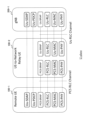
- FIG. 7 is a diagram showing an example of a user plane protocol stack in an assumed scenario.
- FIG. 7 is also an example of a user plane protocol stack in relaying via the relay UE 100-2 (that is, U2N (UE to Network) relaying).
- U2N UE to Network
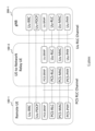
- FIG. 8 shows an example of a control plane protocol stack in an assumed scenario.
- FIG. 8 is also an example of a control plane protocol stack for U2N relaying.
- the gNB 200-1 has a Uu-SRAP (Sidelink Relay Adaptation Protocol) layer, a Uu-RLC layer, a Uu-MAC layer, and a Uu-PHY layer used for communication (Uu communication) on the NR Uu interface.
- Uu-SRAP Segment Relay Adaptation Protocol
- the relay UE 100-2 has a Uu-SRAP layer, a Uu-RLC layer, a Uu-MAC layer, and a Uu-PHY layer used for communication (Uu communication) on the NR Uu interface. Also, the relay UE 100-2 has a PC5-SRAP layer, a PC5-RLC layer, a PC5-MAC layer, and a PC5-PHY layer used for communication on the PC5 interface (PC5 communication).
- the remote UE 100-1 has a Uu-SDAP layer and a Uu-PDCP layer used for communication (Uu) on the Uu interface.
- the remote UE 100-1 also has a PC5-SRAP layer, a PC5-RLC layer, a PC5-MAC layer, and a PC5-PHY layer used for communication on the PC5 interface (PC5 communication).
- the Uu-RRC layer is arranged.
- the SRAP layer is arranged on the Uu interface and the PC5 interface.
- the SRAP layer is an example of a so-called adaptation layer.
- the SRAP layer exists only in layer 2 relays and not in layer 3 relays.
- the SRAP layer exists in all of the remote UE 100-1, the relay UE 100-2, and the gNB 200-1.
- PC5-SRAP and Uu-SRAP have a bearer mapping function. For example, it has the following bearer mapping function.
- the Uu-SRAPs of the remote UE 100-1 and gNB 200-1 perform mapping between bearers (Uu-PDCP) and PC5 RLC channels (PC5-RLC). Also, the PC5-SRAP and Uu-SRAP of the relay UE 100-2 perform mapping between the PC5 RLC channel (PC5-RLC) and the Uu RLC channel (Uu-RLC). Furthermore, Uu-SRAP has the function of identifying the remote UE 100-1.
- each of the remote UE 100-1 and relay UE 100-2 may have an RRC layer for PC5.
- RRC layer is called "PC5-RRC layer”.
- PC5-RRC layer There is a one-to-one correspondence between the PC5-RRC connection and the PC5 unicast link between the remote UE 100-1 and the relay UE 100-2, and the PC5-RRC connection is established after the PC5 unicast link is established.
- each of the remote UE 100-1 and the relay UE 100-2 may have a PC5-S (Signaling) protocol layer.
- the PC5-S protocol layer is a layer above the PDCP layer.
- the PC5-S protocol layer is also a layer for transmitting control information, like the PC5-RRC layer.
- Multipath U2N sidelink relaying is relaying (communication) where one path is a direct link (ie Uu) and the other path is an indirect link (ie U2N sidelink relaying).
- a direct link is a link between a network (eg, a gNB) and remote UE 100-1 that does not go through relay UE 100-2.
- an indirect link is a link between the network and the remote UE 100-1 via the relay UE 100-2.
- split bearers include DC (Dual Connectivity) split bearers and MBS (Multicast and Broadcast Service) split bearers.
- DC split bearer When the DC split bearer is set, the PDCP entity is associated with the RLC entity of the MCG (Master Cell Group) and the RLC entity of the SCG (Secondary Cell Group).
- MBS Multicast and Broadcast Service
- the PDCP entity When a split bearer by MBS is set, the PDCP entity is linked to the RLC entity for PTM (Point-to-Multipoint) and the RLC entity for PTP (Point-to-Point).
- PTM Point-to-Multipoint
- PTP Point-to-Point
- multi-link split bearer is, for example, a split bearer composed of direct links and indirect links.
- priorities are defined between UL transmission (direct link) and sidelink relay (indirect link). Therefore, for example, it is not assumed that the remote UE 100-1 performs UL transmission and sidelink relay at the same time.
- the "multilink split bearer” allows the remote UE 100-1 to transmit the same data using two links or to transmit different data using two links.
- the “multilink split bearer” allows the remote UE 100-1 to use one link for the Control Plane (CP) and the other link for the User Plane (UP). In this way, the "multilink split bearer" makes it possible to support various operations.
- Multilink split bearer can be applied to various forms of sidelink relay.
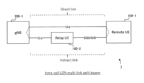
- FIG. 9 shows a configuration example of the mobile communication system 1 when "multilink split bearer" is applied to intra-cell sidelink relay.
- Such a “multi-link split bearer” is called an "intra-cell U2N multi-link split bearer”.
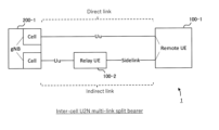
- FIG. 15 shows a configuration example of the mobile communication system 1 when a "multilink split bearer" is applied to inter-cell sidelink relay.
- a "multi-link split bearer” is called an "inter-cell U2N multi-link split bearer”.
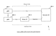
- FIG. 16 shows a configuration example of the mobile communication system 1 when "multilink split bearer" is applied to sidelink relay between gNBs (Inter-gNB).
- Such a "multi-link split bearer” is called an "Inter-gNB U2N multi-link split bearer”.
- FIG. 18 shows a configuration example of the mobile communication system 1 when "multilink split bearer" is applied to U2U (UE to UE) sidelink relay.
- Such a "multi-link split bearer” is called a "U2U multi-link split bearer”.
- Intracell U2N multilink split bearer will be described in the first embodiment. Also, the “inter-cell U2N multilink split bearer” will be described in the third embodiment. Furthermore, the “inter gNB U2N multilink split bearer” will be described in the fourth embodiment. Further, “U2U multilink split bearer” will be described in the fifth embodiment.
- first communication on a direct link between a remote user equipment (for example, remote UE 100-1) and a base station (for example, gNB 200-1) and second communication on an indirect link between a remote user equipment and a base station via a relay user equipment (for example, relay UE 100-2) are possible.
- FIG. 10 is a diagram showing a configuration example of a protocol stack for a multilink split bearer.
- FIG. 10 is also a configuration example of protocol stacks in gNB 200-1 and remote UE 100-1.
- the PDCP entity is associated with a direct link RLC entity (UuRLC entity) and an indirect link SRAP entity.
- UuRLC entity direct link RLC entity
- SRAP entity indirect link SRAP entity
- the base station eg, gNB 200-1
- the remote user equipment binds the PDCP entity to the RLC entity and the SRAP entity according to the binding information.
- the PDCP entity can be associated with the RLC entity and the SRAP entity, so it is possible to set up a "multilink split bearer" with the direct link and the indirect link.
- the split bearer setting method if the direct link is established before the indirect link, there is a method of setting the indirect link and linking the SRAP entity of the indirect link to the PDCP entity. Further, the setting method includes a method of setting the direct link and linking the RLC entity of the direct link to the PDCP entity when the indirect link is established before the direct link. The former will be described first, and then the latter.
- one MAC entity may be set for two links. Also, one MAC entity (Uu-MAC and PC5-MAC) may be set for each of the two links.
- NR Uu may be used as a direct link
- PC5 as an indirect link
- Uu RLC shown in FIG. 10 indicates direct link RLC
- PC5 RLC shown in FIG. 10 indicates indirect link RLC.
- entity and layer may be used without distinction.
- Operation example 1 is an operation example of an "intra-cell U2N multilink split bearer" setting example when a direct link is established first.
- FIG. 11 is a diagram showing operation example 1 according to the first embodiment.
- step S10 a direct link is established between the remote UE 100-1 and the gNB 200-1, not via the relay UE 100-2.
- an indirect link has not been established at this point.
- step S11 the remote UE 100-1 sends a MeasurementReport message to the gNB 200-1 via the direct link.
- the measurement report message also includes the identification information of the relay UE 100-2 (which has not established an indirect link) and the measurement result for this relay UE 100-2.
- step S12 the gNB 200-1 transmits an RRC reconfiguration message to the remote UE 100-1 in response to receiving the measurement report message.
- the RRC Reconfiguration message contains the following information:
- the linking information may be any information that can link the PDCP entity with the RLC entity of the direct link and the SRAP of the indirect link.
- the remote UE 100-1 may transmit a measurement report message triggered by the fact that the radio quality for the relay UE 100-2 is better than the radio quality for the gNB 200-1 on the direct link side (step S11).
- the gNB 200-1 includes information instructing direct link maintenance in the RRC reconfiguration message.
- Information that instructs to maintain a direct link may be hereinafter referred to as “direct link maintenance instruction information”.
- the linking information described above may imply an instruction to maintain the direct link.
- the indirect link establishment instruction information may also be implied to instruct the establishment of the PC5-RRC connection by the linking information described above.
- the indirect link establishment instruction information may include identification information (UE ID, L2 ID, or L2 Destination ID) of the relay UE 100-2.
- the identification information can be indirect link establishment instruction information that instructs the remote UE 100-1 to establish a PC5-RRC connection (indirect link) with the relay UE 100-2.
- the indirect link establishment indication information may include configuration information for each entity of PC5-SRAP, PC5-RLC, PC5-MAC, and PC5-PHY.
- the remote UE 100-1 sends an RRC Reconfiguration Complete (RRCReconfigurationComplete) message via a direct link or via an indirect link to the relay UE 100-2.
- Such information may be referred to as "transmission instruction information”.
- the RRC reconfiguration complete message can be the first message for the relay UE 100-2 in RRC idle state or RRC inactive state.
- the first message is a message for starting an RRC connection with gNB 200-1 in relay UE 100-2 in RRC idle state or RRC inactive state.
- the remote UE 100-1 establishes a PC5-RRC connection with the indicated relay UE 100-2.
- the remote UE 100-1 establishes a PC5-RRC connection, such as by sending an RRC Reconfiguration Sidelink message to the relay UE 100-2.
- the remote UE 100-1 performs relay station reselection instead of the instructed relay UE 100-2, reselects the relay UE 100-2 with the best radio quality, and establishes a PC5-RRC connection with the relay UE 100-2.
- Relay station reselection is, for example, a process in which the remote UE 100-1 reselects the relay UE 100-2 due to movement or the like.
- the remote UE 100-1 may transmit the identification information (UE ID, L2 ID, or L2 Destination ID) of the relay UE 100-2 that has established the PC5-RRC connection through relay station reselection to the gNB 200-1.
- the identification information may be included in the subsequent RRC reconfiguration complete message.
- the remote UE 100-1 maintains the connection with the direct link even after establishing the PC5-RRC connection with the relay UE 100-2 according to the direct link maintenance instruction information.
- the remote UE 100-1 may associate the PDCP entity with the SRAP entity and the RLC entity (Uu RLC entity) according to the association information when establishing the PC5-RRC connection with the relay UE 100-2.
- step S15 the remote UE 100-1 transmits an RRC reconfiguration complete (RRCReconfigurationComplete) message to the gNB 200-1 via the direct link according to the transmission instruction information.
- step S16 the remote UE 100-1 transmits the RRC reconfiguration complete message to the relay UE 100-2 via the PC5 link according to the transmission instruction information.
- the remote UE 100-1 may transmit the RRC reconfiguration complete message on the PC5 link by transmitting a PC5-RRC message encapsulating the RRC reconfiguration complete message to the relay UE 100-2.
- the remote UE 100-1 may send the RRCReconfigurationComplete message on the designated sidelink bearer (SL-SRB or SL-DRB).
- the RRC reconfiguration complete message (or PC5-RRC message) may include the information of the cell ID to be connected.
- Operation example 2 is an operation example of an "intra-cell U2N multilink split bearer" setting example when a direct link is established first.
- FIG. 12 is a diagram showing operation example 2 according to the first embodiment.
- step S20 an indirect link is established between the remote UE 100-1 and the gNB 200-1 via the relay UE 100-2. However, at this point, no direct link has been established between the remote UE 100-1 and the gNB 200-1.
- the remote UE 100-1 transmits a measurement report message to the gNB 200-1 via the relay UE 100-2.
- Remote UE 100-1 transmits a measurement report message as a PC5-RRC message (MeasurementReportSidelink message), and relay UE 100-2 transmits a measurement report message as an RRC message (MeasurementReport message) to gNB 200-1.
- PC5-RRC message MeasurementReportSidelink message
- RRC message MeasurementReport message
- step S22 the gNB 200-1 transmits an RRC reconfiguration message to the remote UE 100-1 via the indirect link in response to receiving the measurement report message.
- the RRC Reconfiguration message contains the following information:
- information on the direct link RLC entity (RLC channel) and the indirect link SRAP entity that are linked with the PDCP entity is included.
- these pieces of information may be the identifier of the RLC entity linked to the PDCP entity and the identifier of the SRAP entity linked to the PDCP entity.
- these pieces of information may be linking information that links these identifiers.
- the linking information may be any information that can link the PDCP entity with the RLC entity of the direct link and the SRAP of the indirect link.
- information that instructs to maintain an indirect link even after establishing a direct link may be referred to as "indirect link maintenance instruction information”.
- the linking information described above may imply an instruction to maintain the indirect link.
- Direct link establishment instruction information may be implied by the above-described tying information instead of the direct link establishment instruction information.
- the direct link establishment indication information may include configuration information for the RLC, MAC, and PHY entities of the direct link.
- transmission instruction information indicating whether to transmit the RRC reconfiguration complete (RRCReconfigurationComplete) message via the direct link or the PC5-RRC message via the indirect link.
- the transmission instruction information may be information indicating to always transmit via a direct link.
- step S24 the remote UE 100-1 establishes a direct link with the gNB 200-1.
- the remote UE 100-1 establishes a direct link using control information or the like included in the RRC reconfiguration message received in step S22.
- the remote UE 100-1 may associate the PDCP entity with the SRAP entity and the RLC entity (Uu RLC entity) according to the association information.
- step S25 the remote UE 100-1 transmits the RRC reconfiguration complete message via the direct link according to the transmission instruction information.
- the remote UE 100-1 transmits the PC5-RRC message via the indirect link according to the transmission indication information.
- one PDCP (DRB or SRB) is linked to a direct link RLC entity and an indirect link SRAP entity.
- one SRAP entity can be associated with a direct link RLC entity and an indirect link RLC entity.
- the base station eg, gNB 200-1
- the remote user equipment eg, remote UE 100-1
- linking information linking the PDCP entity with the first RLC entity of the direct link eg, Uu RLC entity
- the second RLC entity of the indirect link eg, PC5 RLC entity
- the remote user equipment configures an SRAP entity that binds the PDCP entity to the first RLC entity and the second RLC entity according to the binding information.
- FIG. 13 is a diagram showing a configuration example of a protocol stack according to a modification of the first embodiment.
- SRAP is associated with a direct link RLC (Uu RLC) entity, and in SRAP, one bearer (DRB or SRB) is associated with two RLC entities.
- U RLC direct link RLC
- DRB bearer
- operation example 1 and operation example 2 of the first embodiment can be applied to such settings. That is, when the direct link is established first (operation example 1), the following information should be included in the RRC reconfiguration message (step S12 in FIG. 12).
- the PDCP entity contains information indicating that the PDCP entity (DRB or SRB) is to be unlinked from the direct link RLC entity.
- the PDCP entity is associated with the RLC (Uu RLC) entity on the direct link side (for example, the direct link side in FIG. 10).
- the bound PDCP entity and the direct link RLC entity are unbound. Information indicating that such ties are to be removed is included. Note that the information may be implicit information.
- the tying information may be tying information that ties the identifier of each entity, as in the first operation example.
- the remote UE 100-1 can set an SRAP entity that links the PDCP entity to the two RLC entities according to the linking information.
- information for updating the SRAP entity is included in the RRC reconfiguration message. Specifically, it includes the linking information linking the PDCP entity (DRB or SRB) and the direct link RLC (Uu RLC) entity (RLC channel).
- the linking information may be information linking the identifier of each entity.
- the association information may be information that associates a PDCP entity with a direct link RLC entity and an indirect link RLC entity.
- the remote UE 100-1 can configure the SRAP entity that links the PDCP entity to the two RLC entities according to the linking information.
- the SRAP Data PDU header contains the identification information (UE ID (temporary ID or local ID)) of the remote UE 100-1 that performs U2N relay and the bearer ID (Uu radio bearer ID) of the remote UE 100-1.
- the SRAP entity has a bearer mapping function and a remote UE 100-1 identification function, as described above. Therefore, the UEID and the bearer ID included in the SRAP header are used. However, these are functions performed by the SRAP entity set on the indirect link side, and are essentially functions that are not necessary on the direct link side. Therefore, the UEID and the bearer ID included in the SRAP header are less necessary on the direct link side. Alternatively, the UEID included in the SRAP header may not be needed on the direct link side.
- whether or not the SRAP header is required depends on whether or not the SRAP entity is linked to the RLC (Uu RLC) entity of the direct link on the other side (receiving side).
- the SRAP entity of the remote UE 100-1 either outputs the SRAP SDU to the first RLC entity (for example, a direct-link RLC entity) without adding an SRAP header to the SRAP SDU, or outputs the SRAP PDU to which the SRAP SDU has an SRAP header that includes the bearer ID and does not include the UE ID, to the first RLC entity.
- the first RLC entity for example, a direct-link RLC entity
- the SRAP entity of the remote UE 100-1 operates as follows (step S30).
- the SRAP entity processes the SRAP Data SDU as TM (Transparent Mode). That is, the SRAP entity outputs the SRAP Data SDU to the RLC entity of the direct link without adding an SRAP header to the SRAP Data SDU. However, in this case the SRAP entity performs the selection (or mapping) of the direct link RLC entity (or RCL channel). Alternatively, the SRAP entity may remove the SRAP header from the SRAP Data PDU once created, and then output the SRAP Data SDU directly to the RLC entity of the link.
- TM Transparent Mode
- the SRAP entity may output to the RLC entity of the direct link an SRAP Data PDU in which an SRAP header containing the bearer ID and not containing the UE ID of the remote UE 100-1 is added to the SRAP Data SDU.
- the SRAP entity may select and output a Data PDU format different from the PC5-RRC message.
- the gNB 200-1 may perform the following settings for the remote UE 100-1.
- the gNB 200-1 may set whether to attach an SRAP header to the remote UE 100-1. Specifically, it may be a setting as to whether or not to remove the SRAP header. Alternatively, it may be set to specify TM. Designation of TM may be designation of processing mode. Alternatively, it may be configured for each mapped RLC entity. In this case, it may be set for each LCID, or may be set for each RLC channel ID. For example, LCID (Logical Channel ID) #3 may be set to TM, and LCID #4 may be set to normal mode (addition of SRAP header). Alternatively, the processing mode may be specified for each entry in the mapping table.
- the gNB 200-1 may perform the above configuration by sending an RRC message (eg, RRC reconfiguration message) including such configuration information to the remote UE 100-1.
- the remote UE 100-1 executes the above-described process (step S30) according to the above settings.
- RRC message eg, RRC reconfiguration message
- step S30 executes the above-described process (step S30) according to the above settings.
- the base station eg, gNB 200-1
- the base station instructs activation or deactivation of the direct link
- the remote user equipment eg, remote UE 100-1
- the remote user equipment activates or deactivates the direct link and activates or deactivates the indirect link according to the activation indication information.
- a leg means a direct link or an indirect link.
- the remote UE 100-1 may transmit and receive data on the primary link, and when the amount of data buffered for transmission exceeds the threshold, transmit and receive data on both the secondary link and the primary link.
- the primary link is a link that can always transmit and receive data
- the secondary link is a link that can transmit and receive data when certain conditions are met.
- whether the same data or different data is transmitted in the remote UE 100-1 can be set by an RRC message or PDCP Control PDU transmitted from the gNB 200-1.
- UP data can be transmitted on either leg or both legs
- CP control signals can be transmitted on either leg or both legs.
- FIG. 14 is a diagram showing an operation example according to the second embodiment.
- the gNB 200-1 transmits an RRC reconfiguration (RRCReconfiguration) message to the remote UE 100-1 (step S12 or step S20).
- the transmission timing of the RRC reconfiguration message is the same as in the first embodiment. Therefore, the gNB 200-1 may transmit the RRC reconfiguration message via the direct link (step S12) or via the indirect link (step S20). Also, the RRC reconfiguration message includes each information described in the first embodiment.
- the RRC reconfiguration message further includes usage restriction information for direct links and indirect links.
- the use restriction information may be information indicating that the use of both legs is permitted (case (1) above).
- the usage restriction information may include information indicating that both legs are used for transmitting and receiving different data (one leg for transmitting and receiving the first data and the other leg for transmitting and receiving the second data), or may include information indicating that both legs are used for transmitting and receiving the same data (case (2) above).
- information indicating the initial state of activation or deactivation of each leg may be included in the usage restriction information.
- the use restriction information may be information indicating that the use of one leg is permitted (case (1) above).
- the use restriction information may include link indication information indicating a primary link that is always available and a secondary link that is available when the conditions are met (case (1) above).
- the link indication information may include a threshold for permitting use of the secondary link (ie, using both legs).
- the threshold may be the threshold of the transmission data buffer amount.
- the condition for using the secondary link in this case is when the transmission data amount buffer exceeds the threshold.
- the threshold may be a wireless quality threshold.
- the condition for using the secondary link in this case is when the radio quality is better than the threshold or when the radio quality is worse than the threshold.
- the usage restriction information may include information indicating the link for CP and the link for UP (case (3) above).
- the usage restriction information may include information indicating the UL transmission link and the DL reception link (case (4) above).
- the gNB 200-1 may transmit information to the remote UE 100-1 indicating that the direct link should be activated or deactivated and that the indirect link should be activated or deactivated (step S40 or step S41). Such information may be referred to as "activation instruction information".
- the gNB 200-1 may transmit any one of the MAC CE, PDCP Control PDU, and RRC message including the activation instruction information to the remote UE 100-1.
- the RRC message may be an RRC reconfiguration message. In this case, the RRC reconfiguration message may include activation indication information along with usage restriction information.
- the gNB 200-1 may transmit the activation instruction information via the direct link when the direct link is established (step S40), or may transmit the activation instruction information via the indirect link when the indirect link is established (step S41).
- step S42 the remote UE 100-1 performs the following predetermined operations according to the usage restriction information (and activation instruction information).
- the remote UE 100-1 when the remote UE 100-1 receives the activation indication information, it activates or deactivates the direct link and activates or deactivates the indirect link according to the activation indication information.
- the remote UE 100-1 when the remote UE 100-1 receives use restriction information indicating that use of both legs is permitted, PDCCH (Physical Downlink Control Channel) (direct link) and/or PSCCH (Physical Sidelink Control Channel) (indirect link) are monitored for the activated leg. If the remote UE 100-1 is enabled for both legs but one leg is deactivated, it may perform the above monitoring for the activated leg. Also, the remote UE 100-1 may similarly transmit the same data or different data using the activated leg. That is, the remote UE 100-1 transmits the same data to the direct link and the indirect link according to the use restriction information indicating that the direct link and the indirect link are used for transmitting and receiving the same data. Further, the remote UE 100-1 transmits the first data over the direct link and the second data different from the first data over the indirect link according to usage restriction information indicating that the direct link and the indirect link are used for transmitting and receiving different data.
- PDCCH Physical Downlink Control Channel
- PSCCH Physical Sidelink Control Channel
- the remote UE 100-1 when the remote UE 100-1 receives usage restriction information indicating permission to use one leg and receives usage restriction information including link indication information, for example, the following is the case. That is, the remote UE 100-1 sets the primary link and secondary link according to the link indication information. For the DL direction, the remote UE 100-1 may monitor PDCCH (direct link) and/or PSCCH (indirect link) for the activated leg regardless of primary and secondary links. Also, the remote UE 100-1 may perform transmission and reception using the primary link in the UL direction. Then, the remote UE 100-1 uses the threshold included in the link indication information to determine the conditions for using the secondary link, and when the conditions are met, the remote UE 100-1 performs transmission using both the primary link and the secondary link.
- PDCCH direct link
- PSCCH indirect link
- the remote UE 100-1 when the remote UE 100-1 receives use restriction information indicating that the use of one leg is permitted, and receives use restriction information including information indicating the link for CP and the link for UP, for example, it becomes as follows. That is, the remote UE 100-1 transmits and receives control signals using the link designated for CP. Also, the remote UE 100-1 transmits and receives data using the link designated for UP. Both legs may be used in the DL direction.
- the remote UE 100-1 when the remote UE 100-1 receives use restriction information indicating that the use of one leg is permitted, and receives use restriction information including information indicating the UL transmission link and the DL reception link, for example: That is, the remote UE 100-1 performs UL transmission using the link designated for UL. Also, the remote UE 100-1 performs DL reception using the link designated for DL.
- the remote UE 100-1 can transmit the same data using both legs (PDCP duplication) according to the usage restriction information, and use the indirect link for control signals.
- FIG. 15 is a diagram showing a configuration example of the mobile communication system 1 in which "inter-cell U2N multilink split bearer" is set.
- one gNB 200-1 manages multiple cells. Then, a direct link is established between one cell (first cell) of gNB 200-1 and remote UE 100-1, and an indirect link is established between the other cell (second cell) of gNB 200-1 and remote UE 100-1.
- a split bearer is set up with a direct link and an indirect link.
- split bearers are set for the same gNB 200-1, although the cells are different. Therefore, the setting of the "inter-cell U2N multilink split bearer" can be set by the same operation as in the first embodiment. Also, the operation method of the "inter-cell U2N multilink split bearer" can be operated with the same settings as in the second embodiment. [Fourth Embodiment] Next, a fourth embodiment will be described.
- FIG. 16 is a diagram showing a configuration example of the mobile communication system 1 in which the "inter gNB U2N multilink split bearer" is set.
- a direct link is set up between the gNB 200-1 (hereinafter sometimes referred to as "first gNB 200-1”) and the remote UE 100-1.
- an indirect link is set up between the gNB 200-2 (hereinafter sometimes referred to as “second gNB 200-2”) and the remote UE 100-1.
- a split bearer is then set up on the direct link and the indirect link.
- two different gNB 200-1 and gNB 200-2 set up a split bearer with direct and indirect links for the remote UE 100-1.
- the extension of the Xn interface is required in order to enable cooperative control between gNBs 200 .
- the first gNB 200-1 and the second gNB 200-2 are required to share the information of the relay UE 100-2 with each other.
- the first gNB 200-1 transmits an RRC reconfiguration message including the identification information of the relay UE 100-2, etc. to the remote UE 100-1, as in the first embodiment, thereby enabling configuration of the "inter-gNB U2N multilink split bearer".
- the first base station receives a measurement report from the remote user equipment (eg, the remote UE 100-1) via a direct link, and sends a secondary node addition request message including the measurement report to the second base station (eg, the second gNB 200-2).
- the second base station in response to receiving the secondary node addition request message, transmits a secondary node addition request acknowledgment message including identification information about the relay user equipment under its control to the first base station.
- the first base station transmits identification information to the remote user equipment in response to receiving the add secondary node request acknowledgment message.
- the remote UE 100-1 that has established a direct link with the first gNB 200-1 can establish an indirect link via the relay UE 100-2 under the second gNB 200-2 based on the identification information. Therefore, it is possible to set an "inter gNB U2N multilink split bearer".
- the MN Master Node
- the SN Secondary Node
- PC5 the direct link
- the first gNB 200-1 may be called MN 200-1
- the second gNB 200-2 may be called SN 200-2.
- the relay UE is located under the control of SN 200-2.
- FIG. 17 is a diagram showing an operation example according to the fourth embodiment.
- step S50 the MN 200-1 and the remote UE 100-1 have established a direct link. At this point, remote UE 100-1 has not established an indirect link.
- the SN 200-2 may transmit the identification information (UEID) of the relay UE 100-2 under its control to the adjacent gNB (here, gNB 200-1). If the identification information of relay UE 100-2 is included in the subsequent measurement report, it need not be transmitted.
- UEID identification information
- the remote UE 100-1 transmits a MeasurementReport message.
- the measurement report message includes the measurement result of relay UE 100-2.
- the measurement result may include cell information (cell ID) of the serving cell of relay UE 100-2.
- the MN 200-1 determines to set up an "inter-gNB U2N multilink split bearer" for the remote UE 100-1 based on the measurement results, and identifies an appropriate SN. For example, when the measurement result for a certain relay UE is greater than or equal to a predetermined threshold (or less than a predetermined threshold), the MN 200-1 determines to perform the setting and identifies the second gNB 200-2, which has the relay UE under its control, as an appropriate SN.
- the identification of the SN (second gNB 200-2) may use the cell ID included in the measurement result.
- the MN 200-1 transmits an SN Addition Request message to the second gNB 200-2 identified as an appropriate SN.
- the SN addition request message is also, for example, a message that the MN 200-1 requests the second gNB 200-2 to select an appropriate relay UE.
- the Add SN Request message is sent using the Xn interface.
- An SN Modification Request message may be used instead of the SN addition request message.
- the SN addition request also includes the measurement report reported from the remote UE 100-1.
- the measurement result may include the identification information (UEID) of relay UE 100-2 and the measurement result for relay UE 100-2.
- the second gNB 200-2 decides to accept the SN addition request based on the measurement result and identifies an appropriate relay UE. For example, since the measurement result for the relay UE 100-2 is equal to or greater than the predetermined threshold (or less than the predetermined threshold), the second gNB 200-2 determines to accept the SN addition request and identifies the relay UE 100-2 as an appropriate relay UE. By accepting the SN addition request, for example, the second gNB 200-2 may become SN 200-2.
- SN 200-2 transmits an SN Addition Request Acknowledgment message to MN 200-1.
- the SN addition request acknowledgment message includes identification information (UE ID, L2 ID, or L2 Destination ID) of the identified relay UE 100-2.
- the relay UE 100-2 may be the target relay UE for establishing the PC5-RRC connection in the remote UE 100-1.
- the Add SN Request Ack message is also sent using the Xn interface. Instead of the SN addition request acknowledgment message, an SN modification request acknowledgment (SN Modification Request Acknowledgment) message may be used.
- the MN 200-1 sends an RRC Reconfiguration message to the remote UE 100-1 via the direct link.
- the RRC reconfiguration message includes identification information (UE ID, L2 ID, or L2 Destination ID) of the relay UE 100-2. With this identification information, the MN 200-1 indicates to the remote UE 100-1 which relay UE is to establish the PC5-RRC connection.
- the RRC reconfiguration message includes the linking information linking the PDCP entity to the SRAP entity and the RLC (Uu RLC) entity described in the first embodiment.
- the RRC reconfiguration message may include other information described in the first embodiment.
- the RRC reconfiguration message may include the usage restriction information described in the second embodiment.
- the remote UE 100-1 establishes a PC5-RRC connection with the relay UE 100-2 according to the identification information (UE ID, L2 ID, or L2 Destination ID) included in the RRC reconfiguration message.
- Remote UE 100-1 establishes a PC5-RRC connection by sending an RRC Reconfiguration Sidelink message to relay UE 100-2.
- Remote UE 100-1 may transmit to relay UE 100-2 an RRC reconfiguration sidelink message including information (“NW-indicated connection request”) indicating that the connection establishment request is directed by the network as a cause.
- step S59 the remote UE 100-1 transmits an RRC reconfiguration complete (RRCReconfigurationComplete) message to the MN 200-1.
- MN 200-1 transmits the received RRC reconfiguration complete message to SN 200-2 using the Xn interface.
- the remote UE 100-1 may send an RRC reconfiguration complete message to the SN 200-2 via the relay UE 100-2 (or via an indirect link).
- SN 200-2 transmits the RRC reconfiguration complete message to MN 200-1 in response to receiving the RRC reconfiguration complete message via relay UE 100-2.
- SN 200-2 may transmit a message including information indicating that the RRC reconfiguration complete message has been received to MN 200-1.
- the transmission may be done by a PC5-RRC message encapsulating the RRC reconfiguration complete message.
- the relay UE 100-2 when the relay UE 100-2 is in the RRC idle state or the RRC inactive state, the RRC reconfiguration complete message can be the first message described in the first embodiment.
- the relay UE 100-2 establishes an RRC connection with the SN 200-2, enters the RRC connected state, and can execute sidelink relay on the indirect link.
- the remote UE 100-1 may send an RRC reconfiguration complete message to the MN 200-1 before establishing the PC5-RRC connection (step S58).
- the remote UE 100-1 may send a message (such as an RRC reconfiguration complete message) including information indicating that the PC5-RRC connection has been established to the MN 200-1.
- the relay UE 100-2 may transmit a message including access information indicating that the remote UE 100-1 has accessed to the SN 200-2.
- the message may include the identification information (UE ID, L2 ID, or L2 Destination ID) of the remote UE 100-1.
- the access information may be information indicating that a PC5-RRC connection has been established.
- the SN 200-2 may update the radio settings of the relay UE 100-2.
- SN 200-2 may update the SRAP settings.
- an "inter-gNB U2N multilink split bearer” is set.
- various operations can be supported in the same manner as in the second embodiment.
- a fifth embodiment will be described.
- a setting example of "U2U multilink split bearer" will be described.
- FIG. 18 is a diagram showing a configuration example of the mobile communication system 1 according to the fifth embodiment.
- a direct link (PC5) is established between the first remote UE 100-11 and the second remote UE 100-12.
- an indirect link (PC5) is established between the first remote UE 100-11 and the second remote UE 100-12 via the relay UE 100-2.
- a "U2U multi-link split bearer" is set up with direct and indirect links.
- the gNB 200-1 sets the "U2U multilink split bearer" for the first remote UE 100-11, the second remote UE 100-12, and the relay UE 100-2, each embodiment described above is applicable.
- the gNB 200-1 transmits setting information such as the linking information described in the first embodiment to at least one of the first remote UE 100-11, the second remote UE 100-12, and the relay UE 100-2, thereby setting the "U2U multilink split bearer".
- the gNB 200-1 transmits usage restriction information to at least one of the first remote UE 100-11, the second remote UE 100-12, and the relay UE 100-2, thereby enabling various operations described in the second embodiment to be supported.
- a program that causes a computer to execute each process performed by UE 100 (including relay UE 100-2, remote UE 100-1, first remote UE 100-11, and second remote UE 100-12) or gNB 200 may be provided.
- the program may be recorded on a computer readable medium.
- a computer readable medium allows the installation of the program on the computer.
- the computer-readable medium on which the program is recorded may be a non-transitory recording medium.
- the non-transitory recording medium is not particularly limited, but may be, for example, a recording medium such as CD-ROM or DVD-ROM.
- circuits that execute each process performed by the UE 100 or the gNB 200 may be integrated, and at least part of the UE 100 or the gNB 200 may be configured as a semiconductor integrated circuit (chipset, SoC: System on a chip).
- chipsset, SoC System on a chip
- a communication control method in a mobile communication system capable of first communication on a direct link between a remote user equipment and a base station and second communication on an indirect link between the remote user equipment and the base station via a relay user equipment, comprising: said base station sending to said remote user equipment binding information binding a PDCP entity to said direct link RLC entity and said indirect link SRAP entity; said remote user equipment binding said PDCP entity to said RLC entity and said SRAP entity according to said binding information.
- the transmitting step includes: the base station transmitting to the remote user equipment indirect link establishment instruction information instructing to establish the indirect link with the relay user equipment; or the base station transmitting to the remote user equipment direct link establishment instruction information instructing to establish the direct link with the base station.
- the remote user equipment either transmitting direct link maintenance instruction information instructing to maintain the direct link after establishing the indirect link, or transmitting indirect link maintenance instruction information instructing to maintain the indirect link after establishing the direct link;
- the communication control method according to (1) or (2) above.
- the transmitting step includes transmitting, by the base station, transmission indication information to the remote user equipment that instructs the remote user equipment to transmit an RRC reconfiguration complete message to the relay user equipment;
- the communication control method according to any one of (1) to (4) above.
- a communication control method in a mobile communication system capable of first communication on a direct link between a remote user equipment and a base station and second communication on an indirect link between the remote user equipment and the base station via a relay user equipment, comprising: the base station sending to the remote user equipment binding information binding a PDCP entity to a first RLC entity of the direct link and a second RLC entity of the indirect link; said remote user equipment configuring an SRAP entity that links said PDCP entity to said first RLC entity and said second RLC entity according to said linking information.
- the SRAP entity of the remote user equipment outputs the SRAP SDU to the first RLC entity without adding an SRAP header to the SRAP SDU, or outputs the SRAP PDU to which the SRAP header including a bearer ID and not including a UE ID is added to the SRAP SDU to the first RLC entity.
- a communication control method in a mobile communication system capable of first communication on a direct link between a remote user equipment and a base station and second communication on an indirect link between the remote user equipment and the base station via a relay user equipment, comprising: the base station sending activation indication information to the remote user equipment indicating activation or deactivation of the direct link and activation or deactivation of the indirect link; said remote user equipment activating or deactivating said direct link and activating or deactivating said indirect link according to said activation indication information.
- the transmitting step includes the base station transmitting link indication information to the remote user equipment indicating a primary link that is always available and a secondary link that is available if conditions are met; the link indication information includes a threshold for permitting use of the secondary link;
- the transmitting step includes transmitting usage restriction information indicating that the base station uses the direct link and the indirect link for transmission and reception of the same data; Further, the communication control method according to (8) or (9), wherein the remote user device transmits the same data to the direct link and the indirect link according to the use restriction information.
- a communication control method in a mobile communication system capable of first communication on a direct link between a remote user equipment and a first base station and second communication on an indirect link between the remote user equipment and a second base station via a relay user equipment, comprising: sending, in response to the first base station receiving a measurement report from the remote user equipment over the direct link, an add secondary node request message containing the measurement report to the second base station; the second base station, in response to receiving the secondary node addition request message, transmitting a secondary node addition request acknowledgment message including identification information about the relay user equipment under its control to the first base station; said first base station transmitting said identification information to said remote user equipment in response to receiving said secondary node addition request acknowledgment message.
Landscapes
- Engineering & Computer Science (AREA)
- Computer Networks & Wireless Communication (AREA)
- Signal Processing (AREA)
- Mobile Radio Communication Systems (AREA)
Abstract
Un mode de réalisation concerne un procédé de commande de communication pour un système de communication mobile permettant d'assurer une première communication entre un équipement utilisateur distant et une station de base sur une liaison directe, et une seconde communication entre l'équipement utilisateur distant et la station de base sur une liaison indirecte par l'intermédiaire d'un équipement utilisateur relais. Le procédé de commande de communication comprend une étape dans laquelle une station de base transmet, à un équipement utilisateur distant, des informations d'association associant une entité PDCP à une entité RLC d'une liaison directe et à une entité SRAP d'une liaison indirecte. Le procédé de commande de communication comprend en outre une étape dans laquelle l'équipement utilisateur distant associe l'entité PDCP à l'entité RLC et à l'entité SRAP conformément aux informations d'association.
Applications Claiming Priority (2)
| Application Number | Priority Date | Filing Date | Title |
|---|---|---|---|
| US202263301773P | 2022-01-21 | 2022-01-21 | |
| US63/301,773 | 2022-01-21 |
Publications (1)
| Publication Number | Publication Date |
|---|---|
| WO2023140332A1 true WO2023140332A1 (fr) | 2023-07-27 |
Family
ID=87348324
Family Applications (1)
| Application Number | Title | Priority Date | Filing Date |
|---|---|---|---|
| PCT/JP2023/001567 WO2023140332A1 (fr) | 2022-01-21 | 2023-01-19 | Procédé de commande de communication |
Country Status (1)
| Country | Link |
|---|---|
| WO (1) | WO2023140332A1 (fr) |
-
2023
- 2023-01-19 WO PCT/JP2023/001567 patent/WO2023140332A1/fr unknown
Non-Patent Citations (4)
| Title |
|---|
| HUAWEI, HISILICON: "Views on Rel-18 sidelink relay enhancements", 3GPP DRAFT; RP-212291, 3RD GENERATION PARTNERSHIP PROJECT (3GPP), MOBILE COMPETENCE CENTRE ; 650, ROUTE DES LUCIOLES ; F-06921 SOPHIA-ANTIPOLIS CEDEX ; FRANCE, vol. TSG RAN, no. Electronic Meeting; 20210913 - 20210917, 6 September 2021 (2021-09-06), Mobile Competence Centre ; 650, route des Lucioles ; F-06921 Sophia-Antipolis Cedex ; France, XP052049565 * |
| MEDIATEK INC.: "Introduction of Rel-17 Sidelink Relay", 3GPP DRAFT; R2-2111437, 3RD GENERATION PARTNERSHIP PROJECT (3GPP), MOBILE COMPETENCE CENTRE ; 650, ROUTE DES LUCIOLES ; F-06921 SOPHIA-ANTIPOLIS CEDEX ; FRANCE, vol. RAN WG2, no. Electronic; 20211101 - 20211112, 22 November 2021 (2021-11-22), Mobile Competence Centre ; 650, route des Lucioles ; F-06921 Sophia-Antipolis Cedex ; France, XP052082145 * |
| NOKIA, NOKIA SHANGHAI BELL, ERICSSON: "Stage 2 corrections for SL Relay", 3GPP DRAFT; R2-2200944, 3RD GENERATION PARTNERSHIP PROJECT (3GPP), MOBILE COMPETENCE CENTRE ; 650, ROUTE DES LUCIOLES ; F-06921 SOPHIA-ANTIPOLIS CEDEX ; FRANCE, vol. RAN WG2, no. Electronic; 20220117 - 20220125, 11 January 2022 (2022-01-11), Mobile Competence Centre ; 650, route des Lucioles ; F-06921 Sophia-Antipolis Cedex ; France, XP052094062 * |
| SPREADTRUM COMMUNICATIONS: "Sidelink relay enhancement for R18", 3GPP DRAFT; RWS-210059, 3RD GENERATION PARTNERSHIP PROJECT (3GPP), MOBILE COMPETENCE CENTRE ; 650, ROUTE DES LUCIOLES ; F-06921 SOPHIA-ANTIPOLIS CEDEX ; FRANCE, vol. TSG RAN, no. Electronic Meeting; 20210628 - 20210702, 7 June 2021 (2021-06-07), Mobile Competence Centre ; 650, route des Lucioles ; F-06921 Sophia-Antipolis Cedex ; France , XP052025622 * |
Similar Documents
| Publication | Publication Date | Title |
|---|---|---|
| US10708815B2 (en) | Communication control method | |
| US10314043B2 (en) | Mobile terminal and method for data transmission by multiple simultaneous radio access technologies | |
| US8718016B2 (en) | Mobile communication system, base station, and handover execution method | |
| JP7274584B2 (ja) | ハンドオーバ制御方法、中継装置、及びドナー装置 | |
| WO2020032129A1 (fr) | Dispositif de relais | |
| JP7413507B2 (ja) | 通信制御方法 | |
| JP7212204B2 (ja) | 通信制御方法 | |
| US20220201786A1 (en) | Methods and apparatus to reduce packet latency in multi-leg transmission | |
| US20230091236A1 (en) | Communication control method and user equipment | |
| US20180255610A1 (en) | Radio terminal, processor, and network device | |
| WO2023140332A1 (fr) | Procédé de commande de communication | |
| WO2023140333A1 (fr) | Procédé de commande de communication | |
| WO2023140334A1 (fr) | Procédé de commande de communication | |
| WO2023002987A1 (fr) | Procédé de commande de communication | |
| WO2023132285A1 (fr) | Procédé de commande de communication | |
| WO2023068254A1 (fr) | Procédé de commande de communication et nœud de relais | |
| US20230262516A1 (en) | Communication control method | |
| US20240129979A1 (en) | Master node, communication control method, and communication apparatus | |
| WO2024096092A1 (fr) | Dispositif de communication, station de base, et procédé de communication | |
| WO2023013604A1 (fr) | Procédé de commande de communication | |
| WO2023276986A1 (fr) | Nœud maître, dispositif de communication et procédé de commande de communication | |
| WO2024019060A1 (fr) | Dispositif de communication et procédé de communication | |
| WO2024036491A1 (fr) | Assurance de continuité de service par achèvement de transferts | |
| WO2023149577A1 (fr) | Procédé de commande de communication | |
| WO2024036492A1 (fr) | Assurance de continuité de service par facilitation de transferts |
Legal Events
| Date | Code | Title | Description |
|---|---|---|---|
| 121 | Ep: the epo has been informed by wipo that ep was designated in this application |
Ref document number: 23743324 Country of ref document: EP Kind code of ref document: A1 |