WO2023140334A1 - Communication control method - Google Patents
Communication control method Download PDFInfo
- Publication number
- WO2023140334A1 WO2023140334A1 PCT/JP2023/001570 JP2023001570W WO2023140334A1 WO 2023140334 A1 WO2023140334 A1 WO 2023140334A1 JP 2023001570 W JP2023001570 W JP 2023001570W WO 2023140334 A1 WO2023140334 A1 WO 2023140334A1
- Authority
- WO
- WIPO (PCT)
- Prior art keywords
- link
- relay
- remote
- predetermined
- remote user
- Prior art date
Links
Images


Classifications
-
- H—ELECTRICITY
- H04—ELECTRIC COMMUNICATION TECHNIQUE
- H04W—WIRELESS COMMUNICATION NETWORKS
- H04W36/00—Hand-off or reselection arrangements
- H04W36/24—Reselection being triggered by specific parameters
- H04W36/26—Reselection being triggered by specific parameters by agreed or negotiated communication parameters
- H04W36/28—Reselection being triggered by specific parameters by agreed or negotiated communication parameters involving a plurality of connections, e.g. multi-call or multi-bearer connections
-
- H—ELECTRICITY
- H04—ELECTRIC COMMUNICATION TECHNIQUE
- H04W—WIRELESS COMMUNICATION NETWORKS
- H04W36/00—Hand-off or reselection arrangements
- H04W36/34—Reselection control
- H04W36/36—Reselection control by user or terminal equipment
-
- H—ELECTRICITY
- H04—ELECTRIC COMMUNICATION TECHNIQUE
- H04W—WIRELESS COMMUNICATION NETWORKS
- H04W40/00—Communication routing or communication path finding
- H04W40/34—Modification of an existing route
- H04W40/36—Modification of an existing route due to handover
-
- H—ELECTRICITY
- H04—ELECTRIC COMMUNICATION TECHNIQUE
- H04W—WIRELESS COMMUNICATION NETWORKS
- H04W76/00—Connection management
- H04W76/10—Connection setup
- H04W76/15—Setup of multiple wireless link connections
-
- H—ELECTRICITY
- H04—ELECTRIC COMMUNICATION TECHNIQUE
- H04W—WIRELESS COMMUNICATION NETWORKS
- H04W88/00—Devices specially adapted for wireless communication networks, e.g. terminals, base stations or access point devices
- H04W88/02—Terminal devices
- H04W88/04—Terminal devices adapted for relaying to or from another terminal or user
Definitions
- the present disclosure relates to a communication control method used in mobile communication systems.
- sidelink relay technology using user equipment as a relay node is under consideration (see, for example, "3GPP TS 38.300 V16.8.0 (2021-12)").
- Sidelink relaying is a technology in which a relay node called a relay user equipment (Relay UE) intervenes in communication between a base station and a remote user equipment (Remote UE) and relays this communication.
- Relay UE relay user equipment
- a communication control method is a communication control method in a mobile communication system in which first communication on a predetermined link between a first remote user device and a predetermined device and second communication on an indirect link between the first remote user device and a predetermined device via a second relay user device are possible.
- the communication control method comprises, by the first remote user equipment, detecting an indirect link failure.
- the communication control method also includes the step of sending, by the first remote user device, an anomaly notification message including information representing the anomaly to the predetermined device via the predetermined link.
- a communication control method is a communication control method in a mobile communication system in which first communication on a predetermined link between a first remote user equipment and a base station and second communication on an indirect link between the first remote user equipment and a base station via a second relay user equipment are possible.
- the communication control method comprises the steps of: transmitting a first handover notification message including information indicating the handover to the first remote user equipment via an indirect link when the second relay user equipment has handed over to another base station; and transmitting a second handover notification message including information indicating the handover to the second relay user equipment via the indirect link when the first remote user equipment has handed over to another base station.
- a communication control method is a communication control method in a mobile communication system in which first communication on a predetermined link between a first remote user device and a predetermined device and second communication on an indirect link between the first remote user device and a predetermined device via a second relay user device are possible.
- the communication control method comprises the step of performing a relay station reselection procedure by the first remote user equipment. Further, the communication control method includes the step of sending, by the first remote user equipment, a relay station reselection notification message including identification information of the third relay user equipment selected by the relay station reselection process to the predetermined device via the predetermined link.
- a communication control method is a communication control method in a mobile communication system in which first communication on a predetermined link between a first remote user device and a predetermined device and second communication on an indirect link between the first remote user device and a predetermined device via a second relay user device are possible.
- the communication control method comprises detecting, by a first remote user equipment, a radio link failure on an indirect link.
- the communication control method also includes the step of the first remote user equipment not performing relay reselection if the radio quality of the predetermined link is above a threshold.
- FIG. 1 is a diagram showing a configuration example of a mobile communication system according to the first embodiment.
- FIG. 2 is a diagram showing a configuration example of a UE according to the first embodiment.
- FIG. 3 is a diagram showing a configuration example of a gNB according to the first embodiment.
- FIG. 4 is a diagram showing a configuration example of a user plane protocol stack according to the first embodiment.
- FIG. 5 is a diagram showing a configuration example of a protocol stack of the control plane according to the first embodiment.
- FIG. 6 is a diagram showing an assumed scenario according to the first embodiment.
- FIG. 7 is a diagram showing a configuration example of a user plane protocol stack in an assumed scenario according to the first embodiment.
- FIG. 8 is a diagram showing a configuration example of a protocol stack of a control plane in an assumed scenario according to the first embodiment.
- FIG. 9 is a diagram showing a configuration example of a mobile communication system according to the first embodiment.
- FIG. 10 is a diagram showing a configuration example of a mobile communication system according to the first embodiment.
- FIG. 11 is a diagram showing a configuration example of a mobile communication system according to the first embodiment.
- FIG. 12 is a diagram showing a configuration example of a mobile communication system according to the first embodiment.
- FIG. 13 is a diagram showing a configuration example of a mobile communication system according to the first embodiment.
- FIG. 14 is a diagram showing an operation example according to the first embodiment.
- FIG. 15 is a diagram showing an operation example according to the second embodiment.
- FIG. 16 is a diagram showing an operation example according to the third embodiment.
- FIG. 17 is a diagram showing an operation example according to the fourth embodiment.
- a mobile communication system 1 is a 3GPP 5G system.
- the radio access scheme in the mobile communication system 1 is NR (New Radio), which is a 5G radio access scheme.
- NR New Radio
- LTE Long Term Evolution
- 6G future mobile communication systems such as 6G may also be applied to the mobile communication system 1 .
- FIG. 1 is a diagram showing a configuration example of a mobile communication system 1 according to one embodiment.
- the mobile communication system 1 includes a user equipment (UE) 100, a 5G radio access network (NG-RAN: Next Generation Radio Access Network) 10, and a 5G core network (5GC: 5G Core Network) 20.
- UE user equipment
- NG-RAN Next Generation Radio Access Network
- 5GC 5G Core Network
- the UE 100 is a mobile wireless communication device.
- the UE 100 may be any device as long as it is used by the user.
- the UE 100 is a mobile phone terminal (including a smartphone), a tablet terminal, a notebook PC, a communication module (including a communication card or chipset), a sensor or a device provided in a sensor, a vehicle or a device provided in the vehicle (Vehicle UE), an aircraft or a device provided in the aircraft (Aerial UE).
- the NG-RAN 10 includes a base station (called "gNB” in the 5G system) 200.
- the gNBs 200 are interconnected via an Xn interface, which is an interface between base stations.
- the gNB 200 manages one or more cells.
- the gNB 200 performs radio communication with the UE 100 that has established connection with its own cell.
- the gNB 200 has a radio resource management (RRM) function, a user data (hereinafter simply referred to as “data”) routing function, a measurement control function for mobility control/scheduling, and the like.
- RRM radio resource management
- a “cell” is used as a term indicating the minimum unit of a wireless communication area.
- a “cell” is also used as a term indicating a function or resource for radio communication with the UE 100 .
- One cell belongs to one carrier frequency.
- a "cell" and a base station may be used without distinguishing.
- the gNB 200 can also be connected to the EPC (Evolved Packet Core), which is the LTE core network.
- EPC Evolved Packet Core
- LTE base stations can also connect to 5GC20.
- An LTE base station and the gNB 200 can also be connected via an interface between base stations.
- 5GC20 includes AMF (Access and Mobility Management Function) and UPF (User Plane Function) 300.
- AMF performs various mobility control etc. with respect to UE100.
- AMF manages the mobility of UE 100 by communicating with UE 100 using NAS (Non-Access Stratum) signaling.
- the UPF controls data transfer.
- AMF and UPF 300 are connected to gNB 200 via an NG interface, which is a base station-core network interface.
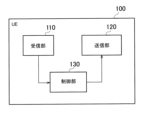
- FIG. 2 is a diagram showing a configuration example of the UE 100. As shown in FIG.
- the UE 100 has a receiver 110, a transmitter 120, and a controller .
- the receiving unit 110 performs various types of reception under the control of the control unit 130.
- Reception section 110 includes an antenna, converts (down-converts) a radio signal received by the antenna into a baseband signal (reception signal), and outputs the baseband signal (reception signal) to control section 130 .
- the transmission unit 120 performs various transmissions under the control of the control unit 130.
- the transmitter 120 includes an antenna, converts (up-converts) a baseband signal (transmission signal) output from the controller 130 into a radio signal, and transmits the radio signal from the antenna.
- the control unit 130 performs various controls in the UE 100.
- Control unit 130 includes at least one memory and at least one processor electrically connected to the memory.
- the memory stores programs executed by the processor and information used for processing by the processor.
- a processor may include a baseband processor and a CPU.
- the baseband processor modulates/demodulates and encodes/decodes the baseband signal.
- the CPU executes programs stored in the memory to perform various processes. Note that the control unit 130 may perform each process and/or each operation in the UE 100 in each embodiment described below.
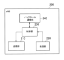
- FIG. 3 is a diagram showing a configuration example of the gNB 200. As shown in FIG.
- the gNB 200 has a transmission section 210, a reception section 220, a control section 230, and a backhaul communication section 240.
- the transmission unit 210 performs various transmissions under the control of the control unit 230.
- Transmitter 210 includes an antenna, converts (up-converts) a baseband signal (transmission signal) output from controller 230 into a radio signal, and transmits the radio signal from the antenna.
- the receiving unit 220 performs various types of reception under the control of the control unit 230.
- Reception section 220 includes an antenna, converts (down-converts) a radio signal received by the antenna into a baseband signal (reception signal), and outputs the baseband signal (reception signal) to control section 230 .
- the control unit 230 performs various controls in the gNB200.
- Control unit 230 includes at least one processor and at least one memory.
- the memory stores programs executed by the processor and information used for processing by the processor.
- a processor may include a baseband processor and a CPU.
- the baseband processor modulates/demodulates and encodes/decodes the baseband signal.
- the CPU executes programs stored in the memory to perform various processes. Note that the control unit 230 may perform each process and/or each operation in the gNB 200 in each embodiment described below.
- the backhaul communication unit 240 is connected to adjacent base stations via the Xn interface.
- the backhaul communication unit 240 is connected to the AMF and UPF 300 via the NG interface.
- the gNB 200 may be composed of a CU (Central Unit) and a DU (Distributed Unit) (that is, functionally divided), and the two units may be connected via an F1 interface.
- FIG. 4 is a diagram showing a configuration example of a protocol stack of a radio interface of a user plane that handles data.
- the user plane radio interface protocol has a physical (PHY) layer, a MAC (Medium Access Control) layer, an RLC (Radio Link Control) layer, a PDCP (Packet Data Convergence Protocol) layer, and an SDAP (Service Data Adaptation Protocol) layer.
- PHY physical
- MAC Medium Access Control
- RLC Radio Link Control
- PDCP Packet Data Convergence Protocol
- SDAP Service Data Adaptation Protocol
- the PHY layer performs encoding/decoding, modulation/demodulation, antenna mapping/demapping, and resource mapping/demapping. Data and control information are transmitted between the PHY layer of the UE 100 and the PHY layer of the gNB 200 via physical channels.
- the MAC layer performs data priority control, hybrid ARQ (HARQ) retransmission processing, random access procedures, and so on. Data and control information are transmitted between the MAC layer of the UE 100 and the MAC layer of the gNB 200 via transport channels.
- the MAC layer of gNB 200 includes a scheduler. The scheduler determines uplink and downlink transport formats (transport block size, modulation and coding scheme (MCS: Modulation and Coding Scheme)) and resource blocks to be allocated to UE 100 .
- MCS modulation and coding scheme
- the RLC layer uses the functions of the MAC layer and PHY layer to transmit data to the RLC layer on the receiving side. Data and control information are transmitted between the RLC layer of the UE 100 and the RLC layer of the gNB 200 via logical channels.
- the PDCP layer performs header compression/decompression and encryption/decryption.
- the SDAP layer maps IP flows, which are units for QoS (Quality of Service) control by the core network, and radio bearers, which are units for QoS control by AS (Access Stratum). Note that SDAP may not be present when the RAN is connected to the EPC.
- FIG. 5 is a diagram showing the configuration of the protocol stack of the radio interface of the control plane that handles signaling (control signals).
- the radio interface protocol stack of the control plane has an RRC (Radio Resource Control) layer and a NAS (Non-Access Stratum) layer instead of the SDAP layer shown in FIG.
- RRC signaling for various settings is transmitted between the RRC layer of the UE 100 and the RRC layer of the gNB 200.
- the RRC layer controls logical, transport and physical channels according to establishment, re-establishment and release of radio bearers.
- RRC connection connection between the RRC of UE 100 and the RRC of gNB 200
- UE 100 is in the RRC connected state.
- RRC connection no connection between RRC of UE 100 and RRC of gNB 200
- UE 100 is in RRC idle state.
- the RRC connection is interrupted (suspended), the UE 100 is in RRC inactive state.
- the NAS layer located above the RRC layer performs session management and mobility management.
- NAS signaling is transmitted between the NAS layer of UE 100 and the NAS layer of AMF 300 .
- the UE 100 has an application layer and the like in addition to the radio interface protocol. [First Embodiment] Next, a first embodiment will be described.
- FIG. 6 is a diagram showing an assumed scenario.
- gNB 200-1 and remote UE 100-1 are scenarios in which communication is performed via relay UE 100-2.
- the remote UE 100-1 performs radio communication (sidelink communication) with the relay UE 100-2 over the PC5 interface (sidelink), which is an interface between UEs.
- the relay UE 100-2 performs radio communication (Uu communication) with the gNB 200-1 over the NR Uu interface.
- Uu communication includes uplink communication and downlink communication.
- FIG. 7 is a diagram showing an example of a user plane protocol stack in an assumed scenario.
- FIG. 7 is also an example of a user plane protocol stack in relaying via the relay UE 100-2 (that is, U2N (UE to Network) relaying).
- U2N UE to Network
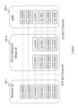
- FIG. 8 shows an example of a control plane protocol stack in an assumed scenario.
- FIG. 8 is also an example of a control plane protocol stack for U2N relaying.
- the gNB 200-1 has a Uu-SRAP (Sidelink Relay Adaptation Protocol) layer, a Uu-RLC layer, a Uu-MAC layer, and a Uu-PHY layer used for communication (Uu communication) on the NR Uu interface.
- Uu-SRAP Segment Relay Adaptation Protocol
- the relay UE 100-2 has a Uu-SRAP layer, a Uu-RLC layer, a Uu-MAC layer, and a Uu-PHY layer used for communication (Uu communication) on the NR Uu interface. Also, the relay UE 100-2 has a PC5-SRAP layer, a PC5-RLC layer, a PC5-MAC layer, and a PC5-PHY layer used for communication on the PC5 interface (PC5 communication).
- the remote UE 100-1 has a Uu-SDAP layer and a Uu-PDCP layer used for communication (Uu) on the Uu interface.
- the remote UE 100-1 also has a PC5-SRAP layer, a PC5-RLC layer, a PC5-MAC layer, and a PC5-PHY layer used for communication on the PC5 interface (PC5 communication).
- the Uu-RRC layer is arranged.
- the SRAP layer is arranged on the Uu interface and the PC5 interface.
- the SRAP layer is an example of a so-called adaptation layer.
- the SRAP layer exists only in layer 2 relays and not in layer 3 relays.
- the SRAP layer exists in all of the remote UE 100-1, the relay UE 100-2, and the gNB 200-1.
- PC5-SRAP and Uu-SRAP have a bearer mapping function. For example, it has the following bearer mapping function.
- the Uu-SRAPs of the remote UE 100-1 and gNB 200-1 perform mapping between bearers (Uu-PDCP) and PC5 RLC channels (PC5-RLC). Also, the PC5-SRAP and Uu-SRAP of the relay UE 100-2 perform mapping between the PC5 RLC channel (PC5-RLC) and the Uu RLC channel (Uu-RLC). Furthermore, Uu-SRAP has the function of identifying the remote UE 100-1.
- each of the remote UE 100-1 and relay UE 100-2 may have an RRC layer for PC5.
- RRC layer is called "PC5-RRC layer”.
- PC5-RRC layer There is a one-to-one correspondence between the PC5-RRC connection and the PC5 unicast link between the remote UE 100-1 and the relay UE 100-2, and the PC5-RRC connection is established after the PC5 unicast link is established.
- each of the remote UE 100-1 and the relay UE 100-2 may have a PC5-S (Signaling) protocol layer.
- the PC5-S protocol layer is a layer above the PDCP layer.
- the PC5-S protocol layer is also a layer for transmitting control information, like the PC5-RRC layer.
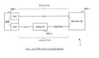
- Multipath U2N sidelink relaying is relaying (communication) where one path is a direct link (ie Uu) and the other path is an indirect link (ie U2N sidelink relaying).
- a direct link is a link between a network (eg, a gNB) and remote UE 100-1 that does not go through relay UE 100-2.
- an indirect link is a link between the network and the remote UE 100-1 via the relay UE 100-2.
- split bearers include DC (Dual Connectivity) split bearers and MBS (Multicast and Broadcast Service) split bearers.
- DC split bearer When the DC split bearer is set, the PDCP entity is associated with the RLC entity of the MCG (Master Cell Group) and the RLC entity of the SCG (Secondary Cell Group).
- MBS Multicast and Broadcast Service
- the PDCP entity When a split bearer by MBS is set, the PDCP entity is linked to the RLC entity for PTM (Point-to-Multipoint) and the RLC entity for PTP (Point-to-Point).
- PTM Point-to-Multipoint
- PTP Point-to-Point
- multi-link split bearer is, for example, a split bearer composed of direct links and indirect links.
- priorities are defined between UL transmission (direct link) and sidelink relay (indirect link). Therefore, for example, it is not assumed that the remote UE 100-1 performs UL transmission and sidelink relay at the same time.
- the "multilink split bearer” allows the remote UE 100-1 to transmit the same data using two links or to transmit different data using two links.
- the “multilink split bearer” allows the remote UE 100-1 to use one link for the Control Plane (CP) and the other link for the User Plane (UP). In this way, the "multilink split bearer" makes it possible to support various operations.
- Multilink split bearer can be applied to various forms of sidelink relay.
- FIG. 9 shows a configuration example of the mobile communication system 1 when "multilink split bearer" is applied to intra-cell sidelink relay.
- Such a “multi-link split bearer” is called an "intra-cell U2N multi-link split bearer”.
- FIG. 10 shows a configuration example of the mobile communication system 1 when a "multilink split bearer" is applied to inter-cell sidelink relay.
- a "multi-link split bearer” is called an "inter-cell U2N multi-link split bearer”.
- FIG. 11 shows a configuration example of the mobile communication system 1 when "multilink split bearer" is applied to sidelink relay between gNBs (Inter-gNB).
- Such a "multi-link split bearer” is called an "Inter-gNB U2N multi-link split bearer”.
- FIG. 12 shows a configuration example of the mobile communication system 1 when "multilink split bearer" is applied to two indirect links set between the network and the remote UE 100-1.
- Such a “multi-link split bearer” is called a “multi-relay U2N multi-link split bearer”.
- FIG. 13 shows a configuration example of the mobile communication system 1 when "multilink split bearer" is applied to U2U (UE to UE) sidelink relay.
- Such a "multi-link split bearer” is called a "U2U multi-link split bearer”.
- the first embodiment is an embodiment applicable to each form of the multilink split bearer set in this way.
- the other link (direct link in FIGS. 9-11 and 13, one indirect link in FIG. 12) may be available.
- the remote UE 100-1 (or the second remote UE 100-12) detects an abnormality in the PC5 link
- an example of transmitting an abnormality notification message to the gNB 200-1 (or the first remote UE 100-11) via the other link will be described.
- the first remote user equipment detects an indirect link failure.
- the first remote user device sends an anomaly notification message containing information indicating the anomaly to a predetermined device (eg, gNB 200-1 or second remote UE 100-12) via a predetermined link (eg, another link different from the indirect link).
- a predetermined device eg, gNB 200-1 or second remote UE 100-12
- the gNB 200-1 (or the second remote UE 100-12) can grasp the abnormality of the PC5 link. Then, the gNB 200-1 can perform various processes such as data transmission stop for the abnormality.
- the first embodiment is applicable to a mobile communication system (for example, mobile communication system 1) in which first communication on a predetermined link between a first remote user device and a predetermined device and second communication on an indirect link between the first remote user device and the predetermined device via a second relay user device are possible.
- a mobile communication system for example, mobile communication system 1
- first communication on a predetermined link between a first remote user device and a predetermined device and second communication on an indirect link between the first remote user device and the predetermined device via a second relay user device are possible.
- the first remote user equipment is, for example, the remote UE 100-1 or the first remote UE 100-11.
- the predetermined device is, for example, the gNB 200-1 or the second remote UE 100-12.
- a predetermined link is, for example, an indirect link or a direct link.
- the second relay user equipment is, for example, the relay UE 100-2 or the second relay UE 100-22.
- FIG. 14 is a diagram showing an operation example according to the first embodiment.
- FIG. 14 shows an operation example when the "intracell U2N multilink split bearer" (FIG. 9) is set as the split bearer.
- a direct link is established between the remote UE 100-1 and gNB 200-1 (step S10).
- an indirect link is established between the remote UE 100-1 and the gNB 200-1 via the relay UE 100-2 (step S11).
- a multilink split bearer ie, “intracell U2N multilink split bearer” is configured on the direct and indirect links.
- the remote UE 100-1 detects Radio Link Failure (RLF) (PC5 RLF) in the PC5 link with the relay UE 100-2.
- RLF Radio Link Failure
- PC5 RLF Radio Link Failure
- a timer may be started, and a radio link failure may be detected when the timer expires without detecting an in-sync state for a second predetermined number of consecutive times.
- the remote UE 100-1 may detect a radio link failure when the number of retransmissions of packets from the remote UE 100-1 to the relay UE 100-2 reaches the maximum value.
- the remote UE 100-1 may detect an abnormality (Uu RLF) on the Uu link side.
- Uu RLF abnormality
- the remote UE 100-1 detects an abnormality in the Uu link, it transmits an abnormality notification message to the gNB 200-1 via the relay UE 100-2.
- the anomaly notification message may include information indicating that the anomaly has occurred in Uu.
- the remote UE 100-1 sends an anomaly notification message to the gNB 200-1 via the direct link.
- the anomaly notification message may include information indicating an anomaly of the PC5 link.
- the anomaly notification message may include information indicating that PC5 RLF has occurred.
- the anomaly notification message may include the identification information (UE ID, L2 ID, or L2 Destination ID) of the relay UE 100-2, which is the other party of the anomaly.
- the anomaly notification message may be sent as an RRC message.
- the first remote UE 100-11 uses the direct link (PC5) to send an anomaly notification message to the second remote UE 100-12.
- the anomaly notification message may be sent as a PC5-RRC message.
- the remote UE 100-1 transmits an abnormality notification message via the first relay UE 100-21 (for example, the first relay user apparatus) in response to an abnormality in the PC5 link with the second relay UE 100-22 (for example, the second relay user apparatus).
- the failure notification message may be sent as a PC5-RRC message on the PC5 link and as an RRC message on the Uu link.
- step S14 the gNB 200-1 performs processing such as stopping communication to the indirect link in response to receiving the anomaly notification message.
- the second remote UE 100-12 performs processing such as stopping communication on the indirect link in response to receiving the anomaly notification message.
- the split bearer shown in FIG. 14 is the "inter gNB U2N multilink split bearer" (FIG. 11)
- the first gNB 200-1 (MN) in response to receiving the anomaly notification message, transmits a message including information indicating communication stop for the indirect link to the second gNB 200-2 (SN) using the Xn interface.
- the second gNB 200-2 performs processing such as communication stop for the indirect link.
- the first embodiment is applicable to all forms of multi-split bearers described above (FIGS. 9-13).
- the remote UE 100-1 sends an anomaly notification message to the gNB 200-1 (FIGS. 9 to 12), and the first remote UE 100-11 sends an anomaly notification message to the second remote UE 100-12 (or the second remote user device) (FIG. 13).
- an anomaly notification message is transmitted via an indirect link (an indirect link via the first relay UE 100-21). Otherwise, including the latter, anomaly notification messages are sent via the direct link.
- the second embodiment is an example of notifying the remote UE 100-1 (or the relay UE 100-2) when the relay UE 100-2 (or the remote UE 100-1) performs handover.
- a first handover notification message including information indicating the handover is transmitted to the first remote user equipment (for example, the remote UE 100-1) via the indirect link
- the second handover notification message including information indicating the handover is sent to the indirect link. to the second relay user equipment via.
- the remote UE 100-1 receives the handover notification message, so processing such as canceling the split bearer setting for the relay UE 100-2 becomes possible. Therefore, the remote UE 100-1 can properly communicate with the gNB 200-1. Also, even when the remote UE 100-1 is handed over, the relay UE 100-2 similarly receives the handover notification message, so processing such as canceling the split bearer setting for the remote UE 100-1 is possible, and communication with the gNB 200-1 can be performed appropriately.
- FIG. 15 is a diagram showing an operation example according to the second embodiment.
- FIG. 15 shows an operation example when the “intracell U2N multilink split bearer” (FIG. 9) is set as the split bearer.
- a direct link is established between the remote UE 100-1 and gNB 200-1 (step S20), and an indirect link is established between the remote UE 100-1 and gNB 200-1 via the relay UE 100-2 (step S21).
- a multilink split bearer ie, “intracell U2N multilink split bearer” is configured on the direct and indirect links.
- step S22 the relay UE 100-2 performs handover to another gNB different from the gNB 200-1.
- the other gNB may not support split bearers.
- the relay UE 100-2 transmits a handover notification message (or first handover message) including information indicating the handover to the remote UE 100-1 via the indirect link.
- the handover notification message may be sent as a PC5-RRC message.
- the handover notification message enables the remote UE 100-1 to grasp that the relay UE 100-2 has performed handover.
- step S24 the remote UE 100-1 cancels the split bearer setting for the relay UE 100-2 or stops data transmission to the relay UE 100-2 in response to receiving the handover notification message.
- the remote UE 100-1 when the remote UE 100-1 is handed over to another gNB, the remote UE 100-1 transmits a handover notification message (or second handover message) including information indicating the handover to the relay UE 100-2 via the indirect link.
- the relay UE 100-2 Upon receiving the handover notification message, the relay UE 100-2 cancels the split bearer setting and stops data transmission to the remote UE 100-1.
- the second embodiment is applicable to split bearer forms (FIGS. 9 to 12) other than the "U2U multilink split bearer" (FIG. 13).
- multi-relay U2N multi-link split bearer (FIG. 12)
- the second relay UE 100-22 transmits a handover notification message to the remote UE 100-1.
- the remote UE 100-1 performs processing such as canceling the split bearer setting.
- the remote UE 100-1 transmits a handover notification message to the second relay UE 100-22 (or the first relay UE 100-21).
- the second relay UE 100-22 (or the first relay UE 100-21) performs processing such as canceling the split bearer setting.
- the third embodiment is an example of notifying the gNB 200-1 (or the second remote UE 100-12) when the remote UE 100-1 (or the first remote UE 100-11) performs relay reselection.
- the first remote user equipment executes the relay station reselection process.
- the first remote user equipment transmits a relay station reselection notification message including identification information of the third relay user equipment selected by the relay station reselection process to a predetermined device (eg, gNB 200-1 or second remote UE 100-12) via a predetermined link (eg, direct link or indirect link).
- a predetermined device eg, gNB 200-1 or second remote UE 100-12
- a predetermined link eg, direct link or indirect link.
- the gNB 200-1 (or the second remote UE 100-12) can grasp that the relay station reselection has been performed by the remote UE 100-1 (or the first remote UE 100-11), so it is possible to set a split bearer for the new relay UE reselected by the relay station reselection. Thereby, it is possible to appropriately perform communication in the mobile communication system 1 .
- FIG. 16 is a diagram showing an operation example according to the third embodiment.
- FIG. 16 shows an operation example when the "intracell U2N multilink split bearer" (FIG. 9) is set as the split bearer.
- a direct link is established between the remote UE 100-1 and gNB 200-1 (step S30), and an indirect link is established between the remote UE 100-1 and gNB 200-1 via the relay UE 100-2 (step S31).
- a multilink split bearer ie, “intracell U2N multilink split bearer” is configured on the direct and indirect links.
- step S32 the remote UE 100-1 performs relay reselection.
- Relay station reselection is performed, for example, so that UE 100 in the RRC idle state or RRC inactive state moves from the current relay UE (eg, relay UE #1) to another relay UE (eg, relay UE #2) as it moves.
- relay station reselection for example, the following processing is performed.
- the remote UE 100-1 may perform relay station reselection when the frequency used for sidelink communication is out of the coverage range. Also, the remote UE 100-1 may perform relay station reselection when the RSRP measurement value of the cell in which it camps on becomes lower than a predetermined threshold. The remote UE 100-1 selects a relay UE whose SD-RSRP (Sidelink Discovery Reference Signal Received Power) exceeds the minimum received RSRP level (minimum received quality level) as a candidate relay UE.
- SD-RSRP Systemlink Discovery Reference Signal Received Power
- the remote UE 100-1 selects the candidate relay UE with the highest radio link (i.e., PC5 unicast link) quality among all the candidate relay UEs that satisfy the predetermined criteria as the relay UE for reselection (e.g., the third relay user equipment). The remote UE 100-1 then reselects the relay UE and camps on the relay UE.
- the candidate relay UE with the highest radio link i.e., PC5 unicast link
- step S33 the remote UE 100-1 sends a relay station reselection notification message to the gNB 200-1 via the direct link.
- This message includes the identification information (UE ID, L2 ID, or L2 Destination ID) of the relay UE reselected by the remote UE 100-1 through relay station reselection.
- the message may include information indicating that the relay station reselection was successful.
- the message may be sent as an RRC message.
- the first remote UE 100-11 performs relay station reselection (step S32) and transmits a relay station reselection notification message to the second remote UE 100-12 via the direct link (step S33).
- the gNB 200-1 that has received the message may, if necessary, update (or change) the split bearer setting to the split bearer via the reselected relay UE (eg, "intracell U2N multilink split bearer").
- the remote UE 100-1 also transmits a relay station reselection notification message when even one relay UE could not be reselected due to relay station reselection (step S33).
- the message may include information indicating that even one relay UE could not be reselected due to relay station reselection. Since the message does not include the identification information of the reselected relay UE, the gNB 200-1 that received the message does not include the identification information, so the remote UE 100-1 reselects the relay UE. It may be understood that it was not possible.
- the gNB 200-1 that received the message deletes the split bearer configuration (de-configure) as necessary.
- the third embodiment can also be applied to all the forms of multi-split bearers described above (FIGS. 9 to 13).
- the remote UE 100-1 transmits the relay station reselection notification message to the gNB 200-1 (FIGS. 9 to 12)
- the first remote UE 100-11 transmits the relay station reselection notification message to the second remote UE 100-12 (FIG. 13).
- the 'multi-relay U2N multi-link split bearer' (Fig. 12) transmits the relay station reselection notification message via the indirect link. Otherwise, including the latter, the relay reselection notification message is sent via the direct link.
- the fourth embodiment is an embodiment regarding what kind of processing is performed under what conditions when one link of the split bearer becomes a radio link failure (RLF).
- RLF radio link failure
- the first remote user equipment detects a radio link failure on the indirect link.
- the first remote user equipment does not perform relay reselection if the radio quality of a given link (eg direct link or indirect link) is above a threshold.
- the remote UE 100-1 will not detect PC5 RLF and unconditionally reselect the relay station, and if the radio quality of one link is equal to or higher than the threshold, the remote UE 100-1 will be able to communicate using that link. Therefore, appropriate communication can be performed in the mobile communication system 1 .
- the first remote user equipment when it detects a radio link failure, it starts a timer, and if the timer expires without recovering from the radio link failure on the indirect link, it deletes the split bearer setting set for the direct link and the indirect link.
- the remote UE 100-1 waits for recovery from the PC5 RLF until a predetermined period of time has passed even if the PC5 RLF occurs, and if it still does not recover, the split bearer setting is deleted. Therefore, split bearers can be set appropriately.
- FIG. 17 is a diagram showing an operation example according to the fourth embodiment.
- FIG. 17 also shows an operation example when the “intracell U2N multilink split bearer” (FIG. 9) is set as the split bearer.
- a direct link is established between the remote UE 100-1 and gNB 200-1 (step S40), and an indirect link is established between the remote UE 100-1 and gNB 200-1 via the relay UE 100-2 (step S41).
- a multilink split bearer ie, “intracell U2N multilink split bearer” is configured on the direct and indirect links.
- the remote UE 100-1 detects a radio link failure (PC5 RLF) on the indirect link.
- PC5 RLF radio link failure
- step S43 the remote UE 100-1 starts counting a timer in response to detection of the PC5 RLF.
- the remote UE 100-1 checks the radio quality of the direct link.
- the radio quality may be SL-RSRP (Sidelink Reference Signal Received Power), SD-RSRP (Sidelink Discovery Reference Signal Received Power), or Uu RSRP.
- the remote UE 100-1 does not perform relay reselection when the direct link radio quality is equal to or higher than the threshold.
- the remote UE 100-1 is able to communicate via a direct link.
- the remote UE 100-1 performs relay station reselection when the radio quality of the direct link is below the threshold.
- the remote UE 100-1 is to ensure communication with the gNB 200-1 via the relay UE reselected by the relay station reselection.
- the threshold may be set from the gNB 200-1.
- the split bearer is a "multi-relay U2N multilink split bearer" (FIG. 12)
- the remote UE 100-1 when the remote UE 100-1 detects PC5 RLF on the indirect link to the second relay UE 100-22, it will check the radio quality of the indirect link to the first relay UE 100-21. Also in this case, the remote UE 100-1 may not perform relay station reselection when the radio quality is equal to or higher than the threshold, and may perform relay station reselection when the radio quality is less than the threshold. Alternatively, the remote UE 100-1 may perform relay station reselection when PC5 RLF is detected for all indirect links. In this case, the remote UE 100-1 may not perform relay station reselection when PC5 RLF is not detected on all indirect links (for example, when PC5 RLF is detected on one indirect link).
- step S45 the remote UE 100-1 stops counting the timer when recovering from the PC5 RLF (returning to normal).
- step S46 the remote UE 100-1 discards the split bearer setting if the timer expires without recovery from the PC5 RLF. Alternatively, if the timer expires without recovery from the PC5 RLF, the remote UE 100-1 may delete the setting of the link in which the radio link failure has occurred from the setting of the split bearer.
- the fourth embodiment can also be applied to all the forms of multi-split bearers described above (FIGS. 9 to 13).
- the remote UE 100-1 is opposite the gNB 200-1 (FIGS. 9 to 12) and a first remote UE 100-11 is opposite the second remote UE 100-12 (FIG. 13).
- the former furthermore, there are cases where split bearers are set with a direct link and an indirect link (FIGS. 9 to 11) and cases where a split bearer is set with two indirect links (FIG. 12). In the latter, split bearers are set for direct and indirect links.
- a program that causes a computer to execute each process performed by the UE 100 (including the relay UE 100-2 and the remote UE 100-1) or the gNB 200 may be provided.
- the program may be recorded on a computer readable medium.
- a computer readable medium allows the installation of the program on the computer.
- the computer-readable medium on which the program is recorded may be a non-transitory recording medium.
- the non-transitory recording medium is not particularly limited, but may be, for example, a recording medium such as CD-ROM or DVD-ROM.
- circuits that execute each process performed by the UE 100 or the gNB 200 may be integrated, and at least part of the UE 100 or the gNB 200 may be configured as a semiconductor integrated circuit (chipset, SoC: System on a chip).
- chipsset, SoC System on a chip
- a communication control method in a mobile communication system capable of first communication on a predetermined link between a first remote user device and a predetermined device and second communication on an indirect link between the first remote user device and the predetermined device via a second relay user device, comprising: detecting, by the first remote user device, an abnormality in the indirect link; said first remote user device sending an anomaly notification message including information indicating said anomaly to said predetermined device via said predetermined link.
- a communication control method in a mobile communication system capable of first communication on a predetermined link between a first remote user equipment and a base station and second communication on an indirect link between the first remote user equipment and the base station via a second relay user equipment, comprising: when the second relay user equipment has handed over to another base station, sending a first handover notification message including information indicating the handover to the first remote user equipment via the indirect link; and transmitting a second handover notification message including information indicating the handover to the second relay user equipment via the indirect link when the first remote user equipment has handed over to the other base station.
- a communication control method in a mobile communication system capable of first communication on a predetermined link between a first remote user device and a predetermined device and second communication on an indirect link between the first remote user device and the predetermined device via a second relay user device, comprising: said first remote user equipment performing a relay station reselection process; said first remote user equipment transmitting a relay station reselection notification message including identification information of a third relay user equipment selected by said relay station reselection process to said predetermined device via said predetermined link.
- a communication control method in a mobile communication system capable of first communication on a predetermined link between a first remote user device and a predetermined device and second communication on an indirect link between the first remote user device and the predetermined device via a second relay user device, comprising: said first remote user equipment detecting a radio link failure on said indirect link; said first remote user equipment not performing relay reselection if the radio quality of said predetermined link is equal to or greater than a threshold.
- the step of not performing relay station reselection includes the first remote user equipment performing the relay station reselection if the radio quality of the given link is below the threshold;
- the first remote user equipment starts a timer when it detects the radio link failure, and if the timer expires without recovery from the radio link failure on the indirect link, deleting the split bearer configuration set on the predetermined link and the indirect link.
- the predetermined device is a base station, said predetermined link is either a direct link between said first remote user device and said predetermined device, or said predetermined link is an indirect link between said first remote user device and said predetermined device via a first relay user device;
- the communication control method according to any one of (1) to (4) above.
- the predetermined device is a second remote user device, said predetermined link is a direct link between said first remote user device and said predetermined device;
- said predetermined link is either a direct link between said first remote user equipment and said base station, or said predetermined link is an indirect link between said first remote user equipment and said base station via a first relay user equipment;
Abstract
This communication control method according to one aspect is a communication control method in a mobile communication system which can perform first communication between a first remote UE and a prescribed device on a prescribed link, and second communication between the first remote UE and the prescribed device through a second relay UE on an indirect link. The communication control method includes detecting, by the first remote UE, abnormality on the indirect link. In addition, the communication control method includes transmitting, by the first remote UE, an abnormality notification message including information indicating the abnormality to the prescribed device through the prescribed link.
Description
本開示は、移動通信システムに用いる通信制御方法に関する。
The present disclosure relates to a communication control method used in mobile communication systems.
3GPP(3rd Generation Partnership Project)規格に基づく移動通信システムにおいて、ユーザ装置を中継ノードとして用いるサイドリンク中継の技術が検討されている(例えば、「3GPP TS 38.300 V16.8.0(2021-12)」参照)。サイドリンク中継は、中継ユーザ装置(Relay UE)と呼ばれる中継ノードが、基地局と遠隔ユーザ装置(Remote UE)との間の通信に介在し、この通信に対する中継を行う技術である。
In a mobile communication system based on the 3GPP (3rd Generation Partnership Project) standard, sidelink relay technology using user equipment as a relay node is under consideration (see, for example, "3GPP TS 38.300 V16.8.0 (2021-12)"). Sidelink relaying is a technology in which a relay node called a relay user equipment (Relay UE) intervenes in communication between a base station and a remote user equipment (Remote UE) and relays this communication.
第1の態様に係る通信制御方法は、第1遠隔ユーザ装置と所定装置との間の所定リンク上の第1通信と、第2中継ユーザ装置を介した第1遠隔ユーザ装置と所定装置との間の間接リンク上の第2通信とが可能な移動通信システムにおける通信制御方法である。前記通信制御方法は、第1遠隔ユーザ装置が、間接リンクの異常を検出するステップを有する。また、前記通信制御方法は、第1遠隔ユーザ装置が、異常を表す情報を含む異常通知メッセージを、所定リンクを介して所定装置へ送信するステップを有する。
A communication control method according to a first aspect is a communication control method in a mobile communication system in which first communication on a predetermined link between a first remote user device and a predetermined device and second communication on an indirect link between the first remote user device and a predetermined device via a second relay user device are possible. The communication control method comprises, by the first remote user equipment, detecting an indirect link failure. The communication control method also includes the step of sending, by the first remote user device, an anomaly notification message including information representing the anomaly to the predetermined device via the predetermined link.
第2の態様に係る通信制御方法は、第1遠隔ユーザ装置と基地局との間の所定リンク上の第1通信と、第2中継ユーザ装置を介した第1遠隔ユーザ装置と基地局との間の間接リンク上の第2通信とが可能な移動通信システムにおける通信制御方法である。前記通信制御方法は、第2中継ユーザ装置が、他の基地局へハンドオーバした場合、当該ハンドオーバを示す情報を含む第1ハンドオーバ通知メッセージを、間接リンクを介して第1遠隔ユーザ装置へ送信すること、及び、第1遠隔ユーザ装置が、他の基地局へハンドオーバした場合、当該ハンドオーバを示す情報を含む第2ハンドオーバ通知メッセージを、間接リンクを介して前記第2中継ユーザ装置へ送信することのいずれかを行うステップを有する。
A communication control method according to a second aspect is a communication control method in a mobile communication system in which first communication on a predetermined link between a first remote user equipment and a base station and second communication on an indirect link between the first remote user equipment and a base station via a second relay user equipment are possible. The communication control method comprises the steps of: transmitting a first handover notification message including information indicating the handover to the first remote user equipment via an indirect link when the second relay user equipment has handed over to another base station; and transmitting a second handover notification message including information indicating the handover to the second relay user equipment via the indirect link when the first remote user equipment has handed over to another base station.
第3の態様に係る通信制御方法は、第1遠隔ユーザ装置と所定装置との間の所定リンク上の第1通信と、第2中継ユーザ装置を介した第1遠隔ユーザ装置と所定装置との間の間接リンク上の第2通信とが可能な移動通信システムにおける通信制御方法である。前記通信制御方法は、第1遠隔ユーザ装置が、中継局再選択処理を実行するステップを有する。また、前記通信制御方法は、第1遠隔ユーザ装置が、中継局再選択処理により選択した第3中継ユーザ装置の識別情報を含む中継局再選択通知メッセージを、所定リンクを介して所定装置へ送信するステップを有する。
A communication control method according to a third aspect is a communication control method in a mobile communication system in which first communication on a predetermined link between a first remote user device and a predetermined device and second communication on an indirect link between the first remote user device and a predetermined device via a second relay user device are possible. The communication control method comprises the step of performing a relay station reselection procedure by the first remote user equipment. Further, the communication control method includes the step of sending, by the first remote user equipment, a relay station reselection notification message including identification information of the third relay user equipment selected by the relay station reselection process to the predetermined device via the predetermined link.
第4の態様に係る通信制御方法は、第1遠隔ユーザ装置と所定装置との間の所定リンク上の第1通信と、第2中継ユーザ装置を介した第1遠隔ユーザ装置と所定装置との間の間接リンク上の第2通信とが可能な移動通信システムにおける通信制御方法である。前記通信制御方法は、第1遠隔ユーザ装置が、間接リンクで無線リンク障害を検出するステップを有する。また、前記通信制御方法は、第1遠隔ユーザ装置が、所定リンクの無線品質が閾値以上の場合、中継局再選択(relay reselection)を行わないステップを有する。
A communication control method according to a fourth aspect is a communication control method in a mobile communication system in which first communication on a predetermined link between a first remote user device and a predetermined device and second communication on an indirect link between the first remote user device and a predetermined device via a second relay user device are possible. The communication control method comprises detecting, by a first remote user equipment, a radio link failure on an indirect link. The communication control method also includes the step of the first remote user equipment not performing relay reselection if the radio quality of the predetermined link is above a threshold.
図面を参照しながら、実施形態に係る移動通信システムについて説明する。図面の記載において、同一又は類似の部分には同一又は類似の符号を付している。
A mobile communication system according to an embodiment will be described with reference to the drawings. In the description of the drawings, the same or similar parts are denoted by the same or similar reference numerals.
(移動通信システムの構成例)
一実施形態に係る移動通信システムの構成例について説明する。一実施形態に係る移動通信システム1は3GPPの5Gシステムである。具体的には、移動通信システム1における無線アクセス方式は、5Gの無線アクセス方式であるNR(New Radio)である。但し、移動通信システム1には、LTE(Long Term Evolution)が少なくとも部分的に適用されてもよい。また、移動通信システム1は、6Gなど、将来の移動通信システムも適用されてよい。 (Configuration example of mobile communication system)
A configuration example of a mobile communication system according to one embodiment will be described. Amobile communication system 1 according to one embodiment is a 3GPP 5G system. Specifically, the radio access scheme in the mobile communication system 1 is NR (New Radio), which is a 5G radio access scheme. However, LTE (Long Term Evolution) may be applied at least partially to the mobile communication system 1 . In addition, future mobile communication systems such as 6G may also be applied to the mobile communication system 1 .
一実施形態に係る移動通信システムの構成例について説明する。一実施形態に係る移動通信システム1は3GPPの5Gシステムである。具体的には、移動通信システム1における無線アクセス方式は、5Gの無線アクセス方式であるNR(New Radio)である。但し、移動通信システム1には、LTE(Long Term Evolution)が少なくとも部分的に適用されてもよい。また、移動通信システム1は、6Gなど、将来の移動通信システムも適用されてよい。 (Configuration example of mobile communication system)
A configuration example of a mobile communication system according to one embodiment will be described. A
図1は、一実施形態に係る移動通信システム1の構成例を示す図である。
FIG. 1 is a diagram showing a configuration example of a mobile communication system 1 according to one embodiment.
図1に示すように、移動通信システム1は、ユーザ装置(UE:User Equipment)100、5Gの無線アクセスネットワーク(NG-RAN:Next Generation Radio Access Network)10と、5Gのコアネットワーク(5GC:5G Core Network)20とを有する。
As shown in FIG. 1, the mobile communication system 1 includes a user equipment (UE) 100, a 5G radio access network (NG-RAN: Next Generation Radio Access Network) 10, and a 5G core network (5GC: 5G Core Network) 20.
UE100は、移動可能な無線通信装置である。UE100は、ユーザにより利用される装置であればどのような装置であっても構わない。例えば、UE100は、携帯電話端末(スマートフォンを含む)やタブレット端末、ノートPC、通信モジュール(通信カード又はチップセットを含む)、センサ若しくはセンサに設けられる装置、車両若しくは車両に設けられる装置(Vehicle UE)、飛行体若しくは飛行体に設けられる装置(Aerial UE)である。
The UE 100 is a mobile wireless communication device. The UE 100 may be any device as long as it is used by the user. For example, the UE 100 is a mobile phone terminal (including a smartphone), a tablet terminal, a notebook PC, a communication module (including a communication card or chipset), a sensor or a device provided in a sensor, a vehicle or a device provided in the vehicle (Vehicle UE), an aircraft or a device provided in the aircraft (Aerial UE).
NG-RAN10は、基地局(5Gシステムにおいて「gNB」と呼ばれる)200を含む。gNB200は、基地局間インターフェイスであるXnインターフェイスを介して相互に接続される。gNB200は、1又は複数のセルを管理する。gNB200は、自セルとの接続を確立したUE100との無線通信を行う。gNB200は、無線リソース管理(RRM)機能、ユーザデータ(以下、単に「データ」という)のルーティング機能、モビリティ制御・スケジューリングのための測定制御機能等を有する。「セル」は、無線通信エリアの最小単位を示す用語として用いられる。「セル」は、UE100との無線通信を行う機能又はリソースを示す用語としても用いられる。1つのセルは1つのキャリア周波数に属する。なお、以下では、「セル」と基地局とを区別しないで用いる場合がある。
The NG-RAN 10 includes a base station (called "gNB" in the 5G system) 200. The gNBs 200 are interconnected via an Xn interface, which is an interface between base stations. The gNB 200 manages one or more cells. The gNB 200 performs radio communication with the UE 100 that has established connection with its own cell. The gNB 200 has a radio resource management (RRM) function, a user data (hereinafter simply referred to as “data”) routing function, a measurement control function for mobility control/scheduling, and the like. A "cell" is used as a term indicating the minimum unit of a wireless communication area. A “cell” is also used as a term indicating a function or resource for radio communication with the UE 100 . One cell belongs to one carrier frequency. In addition, below, a "cell" and a base station may be used without distinguishing.
なお、gNB200がLTEのコアネットワークであるEPC(Evolved Packet Core)に接続することもできる。LTEの基地局が5GC20に接続することもできる。LTEの基地局とgNB200とが基地局間インターフェイスを介して接続されることもできる。
It should be noted that the gNB 200 can also be connected to the EPC (Evolved Packet Core), which is the LTE core network. LTE base stations can also connect to 5GC20. An LTE base station and the gNB 200 can also be connected via an interface between base stations.
5GC20は、AMF(Access and Mobility Management Function)及びUPF(User Plane Function)300を含む。AMFは、UE100に対する各種モビリティ制御等を行う。AMFは、NAS(Non-Access Stratum)シグナリングを用いてUE100と通信することにより、UE100のモビリティを管理する。UPFは、データの転送制御を行う。AMF及びUPF300は、基地局-コアネットワーク間インターフェイスであるNGインターフェイスを介してgNB200と接続される。
5GC20 includes AMF (Access and Mobility Management Function) and UPF (User Plane Function) 300. AMF performs various mobility control etc. with respect to UE100. AMF manages the mobility of UE 100 by communicating with UE 100 using NAS (Non-Access Stratum) signaling. The UPF controls data transfer. AMF and UPF 300 are connected to gNB 200 via an NG interface, which is a base station-core network interface.
(ユーザ装置の構成)
次に、一実施形態に係るユーザ装置であるUE100の構成例について説明する。図2は、UE100の構成例を示す図である。 (Configuration of user device)
Next, a configuration example of the UE 100, which is a user apparatus according to one embodiment, will be described. FIG. 2 is a diagram showing a configuration example of theUE 100. As shown in FIG.
次に、一実施形態に係るユーザ装置であるUE100の構成例について説明する。図2は、UE100の構成例を示す図である。 (Configuration of user device)
Next, a configuration example of the UE 100, which is a user apparatus according to one embodiment, will be described. FIG. 2 is a diagram showing a configuration example of the
図2に示すように、UE100は、受信部110、送信部120、及び制御部130を有する。
As shown in FIG. 2, the UE 100 has a receiver 110, a transmitter 120, and a controller .
受信部110は、制御部130の制御下で各種の受信を行う。受信部110はアンテナを含み、アンテナが受信する無線信号をベースバンド信号(受信信号)に変換(ダウンコンバート)して制御部130に出力する。
The receiving unit 110 performs various types of reception under the control of the control unit 130. Reception section 110 includes an antenna, converts (down-converts) a radio signal received by the antenna into a baseband signal (reception signal), and outputs the baseband signal (reception signal) to control section 130 .
送信部120は、制御部130の制御下で各種の送信を行う。送信部120はアンテナを含み、制御部130が出力するベースバンド信号(送信信号)を無線信号に変換(アップコンバート)してアンテナから送信する。
The transmission unit 120 performs various transmissions under the control of the control unit 130. The transmitter 120 includes an antenna, converts (up-converts) a baseband signal (transmission signal) output from the controller 130 into a radio signal, and transmits the radio signal from the antenna.
制御部130は、UE100における各種の制御を行う。制御部130は、少なくとも1つのメモリと、メモリと電気的に接続された少なくとも1つのプロセッサとを含む。メモリは、プロセッサにより実行されるプログラム、及びプロセッサによる処理に用いられる情報を記憶する。プロセッサは、ベースバンドプロセッサ及びCPUを含んでもよい。ベースバンドプロセッサは、ベースバンド信号の変調・復調及び符号化・復号等を行う。CPUは、メモリに記憶されるプログラムを実行して各種の処理を行う。なお、制御部130は、以下に示す各実施形態において、UE100における各処理及び/又は各動作を行ってもよい。
The control unit 130 performs various controls in the UE 100. Control unit 130 includes at least one memory and at least one processor electrically connected to the memory. The memory stores programs executed by the processor and information used for processing by the processor. A processor may include a baseband processor and a CPU. The baseband processor modulates/demodulates and encodes/decodes the baseband signal. The CPU executes programs stored in the memory to perform various processes. Note that the control unit 130 may perform each process and/or each operation in the UE 100 in each embodiment described below.
(基地局の構成例)
次に、一実施形態に係る基地局であるgNB200の構成例について説明する。図3は、gNB200の構成例を表す図である。 (Base station configuration example)
Next, a configuration example of thegNB 200, which is a base station according to one embodiment, will be described. FIG. 3 is a diagram showing a configuration example of the gNB 200. As shown in FIG.
次に、一実施形態に係る基地局であるgNB200の構成例について説明する。図3は、gNB200の構成例を表す図である。 (Base station configuration example)
Next, a configuration example of the
図3に示すように、gNB200は、送信部210、受信部220、制御部230、及びバックホール通信部240を有する。
As shown in FIG. 3, the gNB 200 has a transmission section 210, a reception section 220, a control section 230, and a backhaul communication section 240.
送信部210は、制御部230の制御下で各種の送信を行う。送信部210は、アンテナを含み、制御部230が出力するベースバンド信号(送信信号)を無線信号に変換(アップコンバート)してアンテナから送信する。
The transmission unit 210 performs various transmissions under the control of the control unit 230. Transmitter 210 includes an antenna, converts (up-converts) a baseband signal (transmission signal) output from controller 230 into a radio signal, and transmits the radio signal from the antenna.
受信部220は、制御部230の制御下で各種の受信を行う。受信部220は、アンテナを含み、アンテナが受信する無線信号をベースバンド信号(受信信号)に変換(ダウンコンバート)して制御部230に出力する。
The receiving unit 220 performs various types of reception under the control of the control unit 230. Reception section 220 includes an antenna, converts (down-converts) a radio signal received by the antenna into a baseband signal (reception signal), and outputs the baseband signal (reception signal) to control section 230 .
制御部230は、gNB200における各種の制御を行う。制御部230は、少なくとも1つのプロセッサ及び少なくとも1つのメモリを含む。メモリは、プロセッサにより実行されるプログラム、及びプロセッサによる処理に用いられる情報を記憶する。プロセッサは、ベースバンドプロセッサと、CPUと、を含んでもよい。ベースバンドプロセッサは、ベースバンド信号の変調・復調及び符号化・復号等を行う。CPUは、メモリに記憶されるプログラムを実行して各種の処理を行う。なお、制御部230は、以下に示す各実施形態において、gNB200における各処理及び/又は各動作を行ってもよい。
The control unit 230 performs various controls in the gNB200. Control unit 230 includes at least one processor and at least one memory. The memory stores programs executed by the processor and information used for processing by the processor. A processor may include a baseband processor and a CPU. The baseband processor modulates/demodulates and encodes/decodes the baseband signal. The CPU executes programs stored in the memory to perform various processes. Note that the control unit 230 may perform each process and/or each operation in the gNB 200 in each embodiment described below.
バックホール通信部240は、Xnインターフェイスを介して隣接基地局と接続される。バックホール通信部240は、NGインターフェイスを介してAMF及びUPF300と接続される。なお、gNB200は、CU(Central Unit)とDU(Distributed Unit)とで構成され(すなわち、機能分割され)、両ユニット間はF1インターフェイスで接続されてもよい。
The backhaul communication unit 240 is connected to adjacent base stations via the Xn interface. The backhaul communication unit 240 is connected to the AMF and UPF 300 via the NG interface. The gNB 200 may be composed of a CU (Central Unit) and a DU (Distributed Unit) (that is, functionally divided), and the two units may be connected via an F1 interface.
(プロトコルスタックの構成例)
図4は、データを取り扱うユーザプレーンの無線インターフェイスのプロトコルスタックの構成例を示す図である。 (Example of protocol stack configuration)
FIG. 4 is a diagram showing a configuration example of a protocol stack of a radio interface of a user plane that handles data.
図4は、データを取り扱うユーザプレーンの無線インターフェイスのプロトコルスタックの構成例を示す図である。 (Example of protocol stack configuration)
FIG. 4 is a diagram showing a configuration example of a protocol stack of a radio interface of a user plane that handles data.
図4に示すように、ユーザプレーンの無線インターフェイスプロトコルは、物理(PHY)レイヤと、MAC(Medium Access Control)レイヤと、RLC(Radio Link Control)レイヤと、PDCP(Packet Data Convergence Protocol)レイヤと、SDAP(Service Data Adaptation Protocol)レイヤとを有する。なお、以下では、レイヤとエンティティとを区別しないで用いる場合がある。
As shown in FIG. 4, the user plane radio interface protocol has a physical (PHY) layer, a MAC (Medium Access Control) layer, an RLC (Radio Link Control) layer, a PDCP (Packet Data Convergence Protocol) layer, and an SDAP (Service Data Adaptation Protocol) layer. In the following description, the terms "layer" and "entity" may not be distinguished from each other.
PHYレイヤは、符号化・復号、変調・復調、アンテナマッピング・デマッピング、及びリソースマッピング・デマッピングを行う。UE100のPHYレイヤとgNB200のPHYレイヤとの間では、物理チャネルを介してデータ及び制御情報が伝送される。
The PHY layer performs encoding/decoding, modulation/demodulation, antenna mapping/demapping, and resource mapping/demapping. Data and control information are transmitted between the PHY layer of the UE 100 and the PHY layer of the gNB 200 via physical channels.
MACレイヤは、データの優先制御、ハイブリッドARQ(HARQ)による再送処理、及びランダムアクセスプロシージャ等を行う。UE100のMACレイヤとgNB200のMACレイヤとの間では、トランスポートチャネルを介してデータ及び制御情報が伝送される。gNB200のMACレイヤはスケジューラを含む。スケジューラは、上下リンクのトランスポートフォーマット(トランスポートブロックサイズ、変調・符号化方式(MCS:Modulation and Coding Scheme))及びUE100への割当リソースブロックを決定する。
The MAC layer performs data priority control, hybrid ARQ (HARQ) retransmission processing, random access procedures, and so on. Data and control information are transmitted between the MAC layer of the UE 100 and the MAC layer of the gNB 200 via transport channels. The MAC layer of gNB 200 includes a scheduler. The scheduler determines uplink and downlink transport formats (transport block size, modulation and coding scheme (MCS: Modulation and Coding Scheme)) and resource blocks to be allocated to UE 100 .
RLCレイヤは、MACレイヤ及びPHYレイヤの機能を利用してデータを受信側のRLCレイヤに伝送する。UE100のRLCレイヤとgNB200のRLCレイヤとの間では、論理チャネルを介してデータ及び制御情報が伝送される。
The RLC layer uses the functions of the MAC layer and PHY layer to transmit data to the RLC layer on the receiving side. Data and control information are transmitted between the RLC layer of the UE 100 and the RLC layer of the gNB 200 via logical channels.
PDCPレイヤは、ヘッダ圧縮・伸張、及び暗号化・復号化を行う。
The PDCP layer performs header compression/decompression and encryption/decryption.
SDAPレイヤは、コアネットワークがQoS(Quality of Service)制御を行う単位であるIPフローと、AS(Access Stratum)がQoS制御を行う単位である無線ベアラとのマッピングを行う。なお、RANがEPCに接続される場合は、SDAPが無くてもよい。
The SDAP layer maps IP flows, which are units for QoS (Quality of Service) control by the core network, and radio bearers, which are units for QoS control by AS (Access Stratum). Note that SDAP may not be present when the RAN is connected to the EPC.
図5は、シグナリング(制御信号)を取り扱う制御プレーンの無線インターフェイスのプロトコルスタックの構成を示す図である。
FIG. 5 is a diagram showing the configuration of the protocol stack of the radio interface of the control plane that handles signaling (control signals).
図5に示すように、制御プレーンの無線インターフェイスのプロトコルスタックは、図4に示したSDAPレイヤに代えて、RRC(Radio Resource Control)レイヤ及びNAS(Non-Access Stratum)レイヤを有する。
As shown in FIG. 5, the radio interface protocol stack of the control plane has an RRC (Radio Resource Control) layer and a NAS (Non-Access Stratum) layer instead of the SDAP layer shown in FIG.
UE100のRRCレイヤとgNB200のRRCレイヤとの間では、各種設定のためのRRCシグナリングが伝送される。RRCレイヤは、無線ベアラの確立、再確立及び解放に応じて、論理チャネル、トランスポートチャネル、及び物理チャネルを制御する。UE100のRRCとgNB200のRRCとの間に接続(RRC接続)がある場合、UE100はRRCコネクティッド状態である。UE100のRRCとgNB200のRRCとの間に接続(RRC接続)がない場合、UE100はRRCアイドル状態である。RRC接続が中断(サスペンド)されている場合、UE100はRRCインアクティブ状態である。
RRC signaling for various settings is transmitted between the RRC layer of the UE 100 and the RRC layer of the gNB 200. The RRC layer controls logical, transport and physical channels according to establishment, re-establishment and release of radio bearers. When there is a connection (RRC connection) between the RRC of UE 100 and the RRC of gNB 200, UE 100 is in the RRC connected state. When there is no connection (RRC connection) between RRC of UE 100 and RRC of gNB 200, UE 100 is in RRC idle state. When the RRC connection is interrupted (suspended), the UE 100 is in RRC inactive state.
RRCレイヤの上位に位置するNASレイヤは、セッション管理及びモビリティ管理等を行う。UE100のNASレイヤとAMF300のNASレイヤとの間では、NASシグナリングが伝送される。
The NAS layer located above the RRC layer performs session management and mobility management. NAS signaling is transmitted between the NAS layer of UE 100 and the NAS layer of AMF 300 .
なお、UE100は、無線インターフェイスのプロトコル以外にアプリケーションレイヤ等を有する。
[第1実施形態]
次に、第1実施形態について説明する。 Note that theUE 100 has an application layer and the like in addition to the radio interface protocol.
[First Embodiment]
Next, a first embodiment will be described.
[第1実施形態]
次に、第1実施形態について説明する。 Note that the
[First Embodiment]
Next, a first embodiment will be described.
(想定シナリオ)
ここで、第1実施形態に係る移動通信システム1における想定シナリオについて説明する。図6は、想定シナリオを表す図である。 (Assumed scenario)
Here, an assumed scenario in themobile communication system 1 according to the first embodiment will be described. FIG. 6 is a diagram showing an assumed scenario.
ここで、第1実施形態に係る移動通信システム1における想定シナリオについて説明する。図6は、想定シナリオを表す図である。 (Assumed scenario)
Here, an assumed scenario in the
図6に示すように、gNB200-1と遠隔UE(Remote UE)100-1との間の通信に中継UE(Relay UE)100-2が介在し、この通信に対する中継を行うサイドリンク中継を用いるシナリオを想定する。言い換えると、gNB200-1と遠隔UE100-1は、中継UE100-2を介して通信を行うシナリオである。
As shown in FIG. 6, assume a scenario in which a relay UE 100-2 intervenes in communication between the gNB 200-1 and a remote UE 100-1, and sidelink relay is used to relay this communication. In other words, gNB 200-1 and remote UE 100-1 are scenarios in which communication is performed via relay UE 100-2.
遠隔UE100-1は、UE間インターフェイスであるPC5インターフェイス(サイドリンク)上で中継UE100-2との無線通信(サイドリンク通信)を行う。中継UE100-2は、NR Uuインターフェイス上でgNB200-1との無線通信(Uu通信)を行う。その結果、遠隔UE100-1は、中継UE100-2を介してgNB200-1と間接的に通信する。Uu通信には、上りリンクの通信及び下りリンクの通信がある。
The remote UE 100-1 performs radio communication (sidelink communication) with the relay UE 100-2 over the PC5 interface (sidelink), which is an interface between UEs. The relay UE 100-2 performs radio communication (Uu communication) with the gNB 200-1 over the NR Uu interface. As a result, the remote UE 100-1 indirectly communicates with the gNB 200-1 via the relay UE 100-2. Uu communication includes uplink communication and downlink communication.
(想定シナリオにおけるプロトコルスタックの構成例)
次に、想定シナリオにおけるプロトコルスタックの構成例について説明する。 (Example of protocol stack configuration in assumed scenario)
Next, a configuration example of a protocol stack in an assumed scenario will be described.
次に、想定シナリオにおけるプロトコルスタックの構成例について説明する。 (Example of protocol stack configuration in assumed scenario)
Next, a configuration example of a protocol stack in an assumed scenario will be described.
図7は、想定シナリオにおけるユーザプレーンのプロトコルスタックの一例を示す図である。図7は、中継UE100-2を介した中継(すなわち、U2N(UE to Network)中継)におけるユーザプレーンのプロトコルスタックの一例でもある。
FIG. 7 is a diagram showing an example of a user plane protocol stack in an assumed scenario. FIG. 7 is also an example of a user plane protocol stack in relaying via the relay UE 100-2 (that is, U2N (UE to Network) relaying).
また、図8は、想定シナリオにおける制御プレーンのプロトコルスタックの一例を示す。図8は、U2N中継における制御プレーンのプロトコルスタックの一例でもある。
Also, FIG. 8 shows an example of a control plane protocol stack in an assumed scenario. FIG. 8 is also an example of a control plane protocol stack for U2N relaying.
図7に示すように、gNB200-1は、NR Uuインターフェイス上の通信(Uu通信)に用いるUu-SRAP(Sidelink Relay Adaptation Protocol)レイヤ、Uu-RLCレイヤ、Uu-MACレイヤ、及びUu-PHYレイヤを有する。
As shown in FIG. 7, the gNB 200-1 has a Uu-SRAP (Sidelink Relay Adaptation Protocol) layer, a Uu-RLC layer, a Uu-MAC layer, and a Uu-PHY layer used for communication (Uu communication) on the NR Uu interface.
中継UE100-2は、NR Uuインターフェイス上の通信(Uu通信)に用いるUu-SRAPレイヤ、Uu-RLCレイヤ、Uu-MACレイヤ、及びUu-PHYレイヤを有する。また、中継UE100-2は、PC5インターフェイス上の通信(PC5通信)に用いるPC5-SRAPレイヤ、PC5-RLCレイヤ、PC5-MACレイヤ、及びPC5-PHYレイヤを有する。
The relay UE 100-2 has a Uu-SRAP layer, a Uu-RLC layer, a Uu-MAC layer, and a Uu-PHY layer used for communication (Uu communication) on the NR Uu interface. Also, the relay UE 100-2 has a PC5-SRAP layer, a PC5-RLC layer, a PC5-MAC layer, and a PC5-PHY layer used for communication on the PC5 interface (PC5 communication).
遠隔UE100-1は、Uuインターフェイス上の通信(Uu)に用いるUu-SDAPレイヤ及びUu-PDCPレイヤを有する。また、遠隔UE100-1は、PC5インターフェイス上の通信(PC5通信)に用いるPC5-SRAPレイヤ、PC5-RLCレイヤ、PC5-MACレイヤ、及びPC5-PHYレイヤを有する。
The remote UE 100-1 has a Uu-SDAP layer and a Uu-PDCP layer used for communication (Uu) on the Uu interface. The remote UE 100-1 also has a PC5-SRAP layer, a PC5-RLC layer, a PC5-MAC layer, and a PC5-PHY layer used for communication on the PC5 interface (PC5 communication).
図8に示すように、コントロールプレーンでは、ユーザプレーンのUu-SDAPレイヤに代えて、Uu-RRCレイヤが配置される。
As shown in FIG. 8, in the control plane, instead of the Uu-SDAP layer in the user plane, the Uu-RRC layer is arranged.
図7と図8に示すように、Uuインターフェイス及びPC5インターフェイス上において、SRAPレイヤが配置される。SRAPレイヤは、所謂アダプテーションレイヤの一例である。SRAPレイヤはレイヤ2中継にのみ存在し、レイヤ3中継には存在しない。また、SRAPレイヤは、遠隔UE100-1、中継UE100-2、及びgNB200-1の全てに存在する。更に、SRAPレイヤは、PC5-SRAPとUu-SRAPの2つレイヤが存在する。PC5-SRAPとUu-SRAPは、ベアラマッピング機能を有する。例えば、以下のようなベアラマッピング機能を有する。すなわち、遠隔UE100-1とgNB200-1のUu-SRAPは、ベアラ(Uu-PDCP)とPC5 RLCチャネル(PC5-RLC)とのマッピングを行う。また、中継UE100-2のPC5-SRAPとUu-SRAPは、PC5 RLCチャネル(PC5-RLC)とUu RLCチャネル(Uu-RLC)とのマッピングを行う。更に、Uu-SRAPは、遠隔UE100-1の識別機能を有する。
As shown in Figures 7 and 8, the SRAP layer is arranged on the Uu interface and the PC5 interface. The SRAP layer is an example of a so-called adaptation layer. The SRAP layer exists only in layer 2 relays and not in layer 3 relays. Also, the SRAP layer exists in all of the remote UE 100-1, the relay UE 100-2, and the gNB 200-1. Furthermore, there are two SRAP layers, PC5-SRAP and Uu-SRAP. PC5-SRAP and Uu-SRAP have a bearer mapping function. For example, it has the following bearer mapping function. That is, the Uu-SRAPs of the remote UE 100-1 and gNB 200-1 perform mapping between bearers (Uu-PDCP) and PC5 RLC channels (PC5-RLC). Also, the PC5-SRAP and Uu-SRAP of the relay UE 100-2 perform mapping between the PC5 RLC channel (PC5-RLC) and the Uu RLC channel (Uu-RLC). Furthermore, Uu-SRAP has the function of identifying the remote UE 100-1.
なお、図7と図8には示されていないが、遠隔UE100-1及び中継UE100-2のそれぞれは、PC5用のRRCレイヤを有してもよい。そのようなRRCレイヤを「PC5-RRCレイヤ」と呼ぶ。遠隔UE100-1と中継UE100-2との間における、PC5-RRC接続と、PC5ユニキャストリンクとは、一対一で対応し、PC5ユニキャストリンクが確立された後にPC5-RRC接続が確立される。
Although not shown in FIGS. 7 and 8, each of the remote UE 100-1 and relay UE 100-2 may have an RRC layer for PC5. Such RRC layer is called "PC5-RRC layer". There is a one-to-one correspondence between the PC5-RRC connection and the PC5 unicast link between the remote UE 100-1 and the relay UE 100-2, and the PC5-RRC connection is established after the PC5 unicast link is established.
また、図7と図8には示されていないが、遠隔UE100-1及び中継UE100-2のそれぞれは、PC5-S(Signaling)プロトコルレイヤを有してもよい。PC5-Sプロトコルレイヤは、PDCPレイヤの上位レイヤである。PC5-Sプロトコルレイヤも、PC5-RRCレイヤと同様に、制御情報送信用のレイヤである。
Also, although not shown in FIGS. 7 and 8, each of the remote UE 100-1 and the relay UE 100-2 may have a PC5-S (Signaling) protocol layer. The PC5-S protocol layer is a layer above the PDCP layer. The PC5-S protocol layer is also a layer for transmitting control information, like the PC5-RRC layer.
(第1実施形態に係る通信制御方法)
3GPPでは、マルチパス(又はマルチリンク)U2N(UE to Network)サイドリンク中継について議論される可能性がある。マルチパスU2Nサイドリンク中継とは、一方のパスが直接リンク(Direct link)(すなわち、Uu)、他方のパスが間接リンク(Indirect link)(すなわち、U2Nサイドリンク中継)による中継(通信)のことである。直接リンク(Direct link)は、中継UE100-2を介さないネットワーク(例えば、gNB)と遠隔UE100-1との間のリンクのことである。また、間接リンク(Indirect link)は、中継UE100-2を介したネットワークと遠隔UE100-1との間のリンクのことである。 (Communication control method according to the first embodiment)
In 3GPP, multipath (or multilink) U2N (UE to Network) sidelink relay may be discussed. Multipath U2N sidelink relaying is relaying (communication) where one path is a direct link (ie Uu) and the other path is an indirect link (ie U2N sidelink relaying). A direct link is a link between a network (eg, a gNB) and remote UE 100-1 that does not go through relay UE 100-2. Also, an indirect link is a link between the network and the remote UE 100-1 via the relay UE 100-2.
他方、3GPPでは、スプリットベアラについて規定している。スプリットベアラには、DC(Dual Connectivity)によるスプリットベアラと、MBS(Multicast and Broadcast Service)によるスプリットベアラがある。DCによるスプリットベアラが設定されると、PDCPエンティティが、MCG(Master Cell Group)のRLCエンティティと、SCG(Secondary Cell Group)のRLCエンティティと紐づけられる。また、MBSによるスプリットベアラが設定されると、PDCPエンティティが、PTM(Point-to-Multipoint)用のRLCエンティティとPTP(Point-to-Point)用のRLCエンティティとに紐づけられる。いずれのスプリットベアラも、PDCPエンティティが、分割された2つのRLCエンティティを紐づけるアンカーポイントとなっている。
On the other hand, 3GPP defines split bearers. Split bearers include DC (Dual Connectivity) split bearers and MBS (Multicast and Broadcast Service) split bearers. When the DC split bearer is set, the PDCP entity is associated with the RLC entity of the MCG (Master Cell Group) and the RLC entity of the SCG (Secondary Cell Group). Also, when a split bearer by MBS is set, the PDCP entity is linked to the RLC entity for PTM (Point-to-Multipoint) and the RLC entity for PTP (Point-to-Point). In any split bearer, the PDCP entity is the anchor point that links the two split RLC entities.
マルチパスU2Nサイドリンク中継とスプリットベアラとを考慮すると、「マルチリンクスプリットベアラ(Multi-link split bearer)」も考えられる。「マルチリンクスプリットベアラ」は、例えば、直接リンクと間接リンクとで構成されたスプリットベアラである。
Considering the multipath U2N sidelink relay and the split bearer, a "multi-link split bearer" is also conceivable. A "multi-link split bearer" is, for example, a split bearer composed of direct links and indirect links.
3GPPでは、UL送信(直接リンク)とサイドリンク中継(間接リンク)との間に優先順位が規定されている。そのため、例えば、遠隔UE100-1がUL送信とサイドリンク中継とを同時に行うことは想定されていない。
In 3GPP, priorities are defined between UL transmission (direct link) and sidelink relay (indirect link). Therefore, for example, it is not assumed that the remote UE 100-1 performs UL transmission and sidelink relay at the same time.
しかし、「マルチリンクスプリットベアラ」により、遠隔UE100-1は、2つのリンクを使用して同一データを送信したり、2つのリンクを使用して異なるデータを送信したりすることもできる。また、「マルチリンクスプリットベアラ」により、遠隔UE100-1は、一方のリンクを制御プレーン(CP:Control Plane)用として使用し、他方のリンクをユーザプレーン(UP:User Plane)として使用することもできる。このように、「マルチリンクスプリットベアラ」により、様々な運用をサポートすることが可能となる。
However, the "multilink split bearer" allows the remote UE 100-1 to transmit the same data using two links or to transmit different data using two links. In addition, the “multilink split bearer” allows the remote UE 100-1 to use one link for the Control Plane (CP) and the other link for the User Plane (UP). In this way, the "multilink split bearer" makes it possible to support various operations.
「マルチリンクスプリットベアラ」は、サイドリンク中継の様々な形態に適用可能である。
"Multilink split bearer" can be applied to various forms of sidelink relay.
例えば、図9は、セル内(Intra-cell)のサイドリンク中継に「マルチリンクスプリットベアラ」を適用した場合の移動通信システム1の構成例を表す。このような「マルチリンクスプリットベアラ」を、「イントラセルU2Nマルチリンクスプリットベアラ(Intra-cell U2N multi-link split bearer)」と呼ぶ。
For example, FIG. 9 shows a configuration example of the mobile communication system 1 when "multilink split bearer" is applied to intra-cell sidelink relay. Such a "multi-link split bearer" is called an "intra-cell U2N multi-link split bearer".
また、例えば、図10は、セル間(Inter-cell)間のサイドリンク中継に「マルチリンクスプリットベアラ」を適用した場合の移動通信システム1の構成例を表している。このような「マルチリンクスプリットベアラ」を、「インターセルU2Nマルチリンクスプリットベアラ(Inter-cell U2N multi-link split bearer)」と呼ぶ。
Also, for example, FIG. 10 shows a configuration example of the mobile communication system 1 when a "multilink split bearer" is applied to inter-cell sidelink relay. Such a "multi-link split bearer" is called an "inter-cell U2N multi-link split bearer".
更に、例えば、図11は、gNB間(Inter-gNB)のサイドリンク中継に「マルチリンクスプリットベアラ」を適用した場合の移動通信システム1の構成例を表している。このような「マルチリンクスプリットベアラ」を、「インターgNB U2Nマルチリンクスプリットベアラ(Inter-gNB U2N multi-link split bearer)」と呼ぶ。
Furthermore, for example, FIG. 11 shows a configuration example of the mobile communication system 1 when "multilink split bearer" is applied to sidelink relay between gNBs (Inter-gNB). Such a "multi-link split bearer" is called an "Inter-gNB U2N multi-link split bearer".
更に、例えば、図12は、ネットワークと遠隔UE100-1との間に設定された2つの間接リンクに「マルチリンクスプリットベアラ」を適用した場合の移動通信システム1の構成例を表している。このような「マルチリンクスプリットベアラ」を、「マルチリレイU2Nマルチリンクスプリットベアラ(Multi-relays U2N multi-link split bearer)」と呼ぶ。
Furthermore, for example, FIG. 12 shows a configuration example of the mobile communication system 1 when "multilink split bearer" is applied to two indirect links set between the network and the remote UE 100-1. Such a "multi-link split bearer" is called a "multi-relay U2N multi-link split bearer".
更に、例えば、図13は、U2U(UE to UE)サイドリンク中継に「マルチリンクスプリットベアラ」を適用した場合の移動通信システム1の構成例を表している。このような「マルチリンクスプリットベアラ」を、「U2Uマルチリンクスプリットベアラ(U2U multi-link split bearer)」と呼ぶ。
Furthermore, for example, FIG. 13 shows a configuration example of the mobile communication system 1 when "multilink split bearer" is applied to U2U (UE to UE) sidelink relay. Such a "multi-link split bearer" is called a "U2U multi-link split bearer".
第1実施形態では、このように設定されたマルチリンクスプリットベアラの各形態に適用可能な実施形態である。
The first embodiment is an embodiment applicable to each form of the multilink split bearer set in this way.
例えば、図9に示す「イントラセルU2Nマルチリンクスプリットベアラ」において、gNB200-1からすると、遠隔UE100-1と中継UE100-2との間のPC5リンクが正常であるのか異常であるのかが分からない、という問題がある。この点は、図10から図12の形態でも同様である。図13に示す「U2Uマルチリンクスプリットベアラ」の場合では、一方の第2遠隔UE100-12からすると、第1遠隔UE100-11と中継UE100-2との間のPC5リンクの状態が分からない、という問題がある。
For example, in the "intracell U2N multilink split bearer" shown in FIG. 9, there is a problem that the gNB 200-1 does not know whether the PC5 link between the remote UE 100-1 and the relay UE 100-2 is normal or abnormal. This point is the same for the forms shown in FIGS. 10 to 12 . In the case of the “U2U multilink split bearer” shown in FIG. 13, there is a problem that the state of the PC5 link between the first remote UE 100-11 and the relay UE 100-2 is not known from the second remote UE 100-12.
一方で、もう一方のリンク(図9~図11と図13における直接リンク、図12における一方の間接リンク)は使用可能な場合がある。
On the other hand, the other link (direct link in FIGS. 9-11 and 13, one indirect link in FIG. 12) may be available.
そこで、第1実施形態では、遠隔UE100-1(又は第2遠隔UE100-12)は、PC5リンクで異常を検知した場合、もう一方のリンクを介して、異常通知メッセージをgNB200-1(又は第1遠隔UE100-11)へ送信する例について説明する。
Therefore, in the first embodiment, when the remote UE 100-1 (or the second remote UE 100-12) detects an abnormality in the PC5 link, an example of transmitting an abnormality notification message to the gNB 200-1 (or the first remote UE 100-11) via the other link will be described.
具体的には、第1に、第1遠隔ユーザ装置(例えば、遠隔UE100-1又は第1遠隔UE100-11)が、間接リンクの異常を検出する。第2に、第1遠隔ユーザ装置が、異常を表す情報を含む異常通知メッセージを、所定リンク(例えば、当該間接リンクとは異なるもう一方のリンク)を介して所定装置(例えば、gNB200-1又は第2遠隔UE100-12)へ送信する。
Specifically, first, the first remote user equipment (for example, the remote UE 100-1 or the first remote UE 100-11) detects an indirect link failure. Second, the first remote user device sends an anomaly notification message containing information indicating the anomaly to a predetermined device (eg, gNB 200-1 or second remote UE 100-12) via a predetermined link (eg, another link different from the indirect link).
これにより、gNB200-1(又は第2遠隔UE100-12)は、PC5リンクの異常を把握することができる。そして、gNB200-1は、当該異常に対してデータ送信停止などの様々な処理を行うことができる。
As a result, the gNB 200-1 (or the second remote UE 100-12) can grasp the abnormality of the PC5 link. Then, the gNB 200-1 can perform various processes such as data transmission stop for the abnormality.
なお、第1実施形態は、第1遠隔ユーザ装置と所定装置との間の所定リンク上の第1通信と、第2中継ユーザ装置を介した前記第1遠隔ユーザ装置と前記所定装置との間の間接リンク上の第2通信とが可能な移動通信システム(例えば、移動通信システム1)に適用可能である。
It should be noted that the first embodiment is applicable to a mobile communication system (for example, mobile communication system 1) in which first communication on a predetermined link between a first remote user device and a predetermined device and second communication on an indirect link between the first remote user device and the predetermined device via a second relay user device are possible.
ここで、第1遠隔ユーザ装置は、例えば、遠隔UE100-1又は第1遠隔UE100-11である。所定装置は、例えば、gNB200-1又は第2遠隔UE100-12である。所定リンクは、例えば、間接リンク又は直接リンクである。第2中継ユーザ装置は、例えば、中継UE100-2又は第2中継UE100-22である。
Here, the first remote user equipment is, for example, the remote UE 100-1 or the first remote UE 100-11. The predetermined device is, for example, the gNB 200-1 or the second remote UE 100-12. A predetermined link is, for example, an indirect link or a direct link. The second relay user equipment is, for example, the relay UE 100-2 or the second relay UE 100-22.
他の実施形態についても、基本的にはこのような移動通信システム1に適用可能である。
Other embodiments are basically applicable to such a mobile communication system 1 as well.
(第1実施形態に係る動作例)
図14は、第1実施形態に係る動作例を表す図である。図14は、スプリットベアラとして、「イントラセルU2Nマルチリンクスプリットベアラ」(図9)が設定された場合の動作例を表している。 (Example of operation according to the first embodiment)
FIG. 14 is a diagram showing an operation example according to the first embodiment. FIG. 14 shows an operation example when the "intracell U2N multilink split bearer" (FIG. 9) is set as the split bearer.
図14に示すように、遠隔UE100-1とgNB200-1との間で直接リンク(Uu)が確立されている(ステップS10)。また、遠隔UE100-1とgNB200-1との間では、中継UE100-2を介した間接リンク(PC5、Uu)が確立されている(ステップS11)。直接リンクと間接リンクとで、マルチリンクスプリットベアラ(すなわち、「イントラセルU2Nマルチリンクスプリットベアラ」)が設定されている。
As shown in FIG. 14, a direct link (Uu) is established between the remote UE 100-1 and gNB 200-1 (step S10). Also, an indirect link (PC5, Uu) is established between the remote UE 100-1 and the gNB 200-1 via the relay UE 100-2 (step S11). A multilink split bearer (ie, “intracell U2N multilink split bearer”) is configured on the direct and indirect links.
ステップS12において、遠隔UE100-1は、中継UE100-2とのPC5リンクにおいて、無線リンク障害(RLF:Radio Link Failure)(PC5 RLF)を検出する。例えば、遠隔UE100-1が中継UE100-2に対して同期外れ状態(out-of-sync)を第1所定回数連続で検出した後、タイマを始動させ、同期状態(in-sync)を第2所定回数連続で検出することなくタイマが満了した場合に無線リンク障害を検出してもよい。また、例えば、遠隔UE100-1の中継UE100-2に対するパケットの再送回数が最大値に達した場合に、遠隔UE100-1が無線リンク障害を検出してもよい。もしくは、遠隔UE100-1は、Uuリンク側の異常(Uu RLF)を検出してもよい。遠隔UE100-1は、Uuリンクの異常を検出した場合、異常通知メッセージを、中継UE100-2経由でgNB200-1へ送信する。当該異常通知メッセージは、当該異常がUuで発生したことを示す情報を含んでもよい。
In step S12, the remote UE 100-1 detects Radio Link Failure (RLF) (PC5 RLF) in the PC5 link with the relay UE 100-2. For example, after the remote UE 100-1 detects an out-of-sync state with respect to the relay UE 100-2 for a first predetermined number of consecutive times, a timer may be started, and a radio link failure may be detected when the timer expires without detecting an in-sync state for a second predetermined number of consecutive times. Further, for example, the remote UE 100-1 may detect a radio link failure when the number of retransmissions of packets from the remote UE 100-1 to the relay UE 100-2 reaches the maximum value. Alternatively, the remote UE 100-1 may detect an abnormality (Uu RLF) on the Uu link side. When the remote UE 100-1 detects an abnormality in the Uu link, it transmits an abnormality notification message to the gNB 200-1 via the relay UE 100-2. The anomaly notification message may include information indicating that the anomaly has occurred in Uu.
ステップS13において、遠隔UE100-1は、異常通知メッセージを、直接リンクを介してgNB200-1へ送信する。異常通知メッセージには、PC5リンクの異常を示す情報が含まれてもよい。異常通知メッセージには、PC5 RLFが発生したことを示す情報が含まれてもよい。異常通知メッセージには、異常の相手方となる中継UE100-2の識別情報(UEID、L2 ID、又はL2 Destination ID)が含まれてもよい。異常通知メッセージは、RRCメッセージとして送信されてもよい。
In step S13, the remote UE 100-1 sends an anomaly notification message to the gNB 200-1 via the direct link. The anomaly notification message may include information indicating an anomaly of the PC5 link. The anomaly notification message may include information indicating that PC5 RLF has occurred. The anomaly notification message may include the identification information (UE ID, L2 ID, or L2 Destination ID) of the relay UE 100-2, which is the other party of the anomaly. The anomaly notification message may be sent as an RRC message.
なお、図14に示すスプリットベアラが「U2Uマルチリンクスプリットベアラ」(図13)の場合、第1遠隔UE100-11は直接リンク(PC5)を利用して第2遠隔UE100-12へ異常通知メッセージを送信する。この場合、異常通知メッセージは、PC5-RRCメッセージとして送信されてもよい。
If the split bearer shown in FIG. 14 is the "U2U multilink split bearer" (FIG. 13), the first remote UE 100-11 uses the direct link (PC5) to send an anomaly notification message to the second remote UE 100-12. In this case, the anomaly notification message may be sent as a PC5-RRC message.
また、図14に示すスプリットベアラが「マルチリレイU2Nマルチリンクスプリットベアラ」(図12)の場合、遠隔UE100-1は、第2中継UE100-22(例えば、第2中継ユーザ装置)とのPC5リンクの異常に対して、異常通知メッセージを、第1中継UE100-21(例えば、第1中継ユーザ装置)を介して送信する。異常通知メッセージは、PC5リンクではPC5-RRCメッセージ、UuリンクではRRCメッセージとして送信されてもよい。
In addition, when the split bearer shown in FIG. 14 is a "multi-relay U2N multilink split bearer" (FIG. 12), the remote UE 100-1 transmits an abnormality notification message via the first relay UE 100-21 (for example, the first relay user apparatus) in response to an abnormality in the PC5 link with the second relay UE 100-22 (for example, the second relay user apparatus). The failure notification message may be sent as a PC5-RRC message on the PC5 link and as an RRC message on the Uu link.
ステップS14において、gNB200-1は、異常通知メッセージを受信したことに応じて、間接リンクへの通信を停止するなどの処理を行う。
In step S14, the gNB 200-1 performs processing such as stopping communication to the indirect link in response to receiving the anomaly notification message.
なお、図14に示すスプリットベアラが「U2Uマルチリンクスプリットベアラ」(図13)の場合、第2遠隔UE100-12が異常通知メッセージを受信したことに応じて、間接リンクに対する通信停止などの処理を行う。
If the split bearer shown in FIG. 14 is the "U2U multilink split bearer" (FIG. 13), the second remote UE 100-12 performs processing such as stopping communication on the indirect link in response to receiving the anomaly notification message.
また、図14に示すスプリットベアラが「インターgNB U2Nマルチリンクスプリットベアラ」(図11)の場合、第1gNB200-1(MN)は、異常通知メッセージを受信したことに応じて、間接リンクに対する通信停止を示す情報を含むメッセージを、Xnインターフェイスを利用して第2gNB200-2(SN)へ送信する。第2gNB200-2では、当該メッセージに従って、間接リンクに対する通信停止の処理などを行う。
In addition, when the split bearer shown in FIG. 14 is the "inter gNB U2N multilink split bearer" (FIG. 11), the first gNB 200-1 (MN), in response to receiving the anomaly notification message, transmits a message including information indicating communication stop for the indirect link to the second gNB 200-2 (SN) using the Xn interface. In accordance with the message, the second gNB 200-2 performs processing such as communication stop for the indirect link.
第1実施形態は、上述したマルチスプリットベアラの全ての形態(図9~図13)に適用可能である。これらの形態においては、遠隔UE100-1が異常通知メッセージを送信する相手方がgNB200-1である場合(図9~図12)と、第1遠隔UE100-11が異常通知メッセージを送信する相手方が第2遠隔UE100-12(又は第2遠隔ユーザ装置)である場合(図13)とがある。前者のうち、「マルチリレイU2Nマルチリンクスプリットベアラ」では間接リンク(第1中継UE100-21を介した間接リンク)を介して異常通知メッセージが送信される。それ以外は、後者を含めて、直接リンクを介して異常通知メッセージが送信される。
[第2実施形態]
次に、第2実施形態について説明する。 The first embodiment is applicable to all forms of multi-split bearers described above (FIGS. 9-13). In these forms, the remote UE 100-1 sends an anomaly notification message to the gNB 200-1 (FIGS. 9 to 12), and the first remote UE 100-11 sends an anomaly notification message to the second remote UE 100-12 (or the second remote user device) (FIG. 13). Among the former, in the "multi-relay U2N multi-link split bearer", an anomaly notification message is transmitted via an indirect link (an indirect link via the first relay UE 100-21). Otherwise, including the latter, anomaly notification messages are sent via the direct link.
[Second embodiment]
Next, a second embodiment will be described.
第2実施形態は、中継UE100-2(又は遠隔UE100-1)がハンドオーバを行った場合、遠隔UE100-1(又は中継UE100-2)へ通知を行う例である。
The second embodiment is an example of notifying the remote UE 100-1 (or the relay UE 100-2) when the relay UE 100-2 (or the remote UE 100-1) performs handover.
具体的には、第2中継ユーザ装置(例えば、中継UE100-2又は第2中継UE100-22)が、他の基地局へハンドオーバした場合、当該ハンドオーバを示す情報を含む第1ハンドオーバ通知メッセージを、間接リンクを介して第1遠隔ユーザ装置(例えば、遠隔UE100-1)へ送信すること、及び、第1遠隔ユーザ装置が、他の基地局へハンドオーバした場合、当該ハンドオーバを示す情報を含む第2ハンドオーバ通知メッセージを、間接リンクを介して第2中継ユーザ装置へ送信することのいずれかを行う。
Specifically, when the second relay user equipment (for example, the relay UE 100-2 or the second relay UE 100-22) has handed over to another base station, a first handover notification message including information indicating the handover is transmitted to the first remote user equipment (for example, the remote UE 100-1) via the indirect link, and when the first remote user equipment has handed over to another base station, the second handover notification message including information indicating the handover is sent to the indirect link. to the second relay user equipment via.
これにより、例えば、中継UE100-2が、スプリットベアラをサポートしていない他の基地局へハンドオーバした場合でも、遠隔UE100-1は、ハンドオーバ通知メッセージを受信するため、当該中継UE100-2に対するスプリットベアラの設定を解除する等の処理が可能となる。従って、遠隔UE100-1は、gNB200-1に対する通信を適切に行うことができる。また、遠隔UE100-1がハンドオーバした場合であっても、同様に、中継UE100-2は、ハンドオーバ通知メッセージを受信するため、遠隔UE100-1に対するスプリットベアラの設定を解除する等の処理が可能となり、gNB200-1に対する通信を適切に行うことができる。
As a result, for example, even if the relay UE 100-2 is handed over to another base station that does not support split bearers, the remote UE 100-1 receives the handover notification message, so processing such as canceling the split bearer setting for the relay UE 100-2 becomes possible. Therefore, the remote UE 100-1 can properly communicate with the gNB 200-1. Also, even when the remote UE 100-1 is handed over, the relay UE 100-2 similarly receives the handover notification message, so processing such as canceling the split bearer setting for the remote UE 100-1 is possible, and communication with the gNB 200-1 can be performed appropriately.
(第2実施形態に係る動作例)
次に、第2実施形態に係る動作例について説明する。 (Example of operation according to the second embodiment)
Next, an operation example according to the second embodiment will be described.
次に、第2実施形態に係る動作例について説明する。 (Example of operation according to the second embodiment)
Next, an operation example according to the second embodiment will be described.
図15は、第2実施形態に係る動作例を表す図である。図15は、スプリットベアラとして、「イントラセルU2Nマルチリンクスプリットベアラ」(図9)が設定された場合の動作例を表している。
FIG. 15 is a diagram showing an operation example according to the second embodiment. FIG. 15 shows an operation example when the “intracell U2N multilink split bearer” (FIG. 9) is set as the split bearer.
図15に示すように、遠隔UE100-1とgNB200-1との間では直接リンクが確立され(ステップS20)、遠隔UE100-1とgNB200-1との間では中継UE100-2を介して間接リンクが確立されている(ステップS21)。直接リンクと間接リンクとで、マルチリンクスプリットベアラ(すなわち、「イントラセルU2Nマルチリンクスプリットベアラ」)が設定されている。
As shown in FIG. 15, a direct link is established between the remote UE 100-1 and gNB 200-1 (step S20), and an indirect link is established between the remote UE 100-1 and gNB 200-1 via the relay UE 100-2 (step S21). A multilink split bearer (ie, “intracell U2N multilink split bearer”) is configured on the direct and indirect links.
ステップS22において、中継UE100-2は、gNB200-1とは異なる他のgNBへハンドオーバを行う。当該他のgNBはスプリットベアラがサポートされていなくてもよい。
In step S22, the relay UE 100-2 performs handover to another gNB different from the gNB 200-1. The other gNB may not support split bearers.
ステップS23において、中継UE100-2は、当該ハンドオーバを示す情報を含むハンドオーバ通知メッセージ(又は第1ハンドオーバメッセージ)を、間接リンクを介して遠隔UE100-1へ送信する。ハンドオーバ通知メッセージは、PC5-RRCメッセージとして送信されてもよい。遠隔UE100-1は、ハンドオーバ通知メッセージにより、中継UE100-2においてハンドオーバが行われたことを把握すること可能となる。
In step S23, the relay UE 100-2 transmits a handover notification message (or first handover message) including information indicating the handover to the remote UE 100-1 via the indirect link. The handover notification message may be sent as a PC5-RRC message. The handover notification message enables the remote UE 100-1 to grasp that the relay UE 100-2 has performed handover.
ステップS24において、遠隔UE100-1は、ハンドオーバ通知メッセージを受信したことに応じて、中継UE100-2に対するスプリットベアラの設定を解除したり、中継UE100-2に対するデータ送信を停止したりする。
In step S24, the remote UE 100-1 cancels the split bearer setting for the relay UE 100-2 or stops data transmission to the relay UE 100-2 in response to receiving the handover notification message.
中継UE100-2ではなく、遠隔UE100-1がハンドオーバした場合は、以下となる。
When the remote UE 100-1, not the relay UE 100-2, performs handover, the following is the case.
すなわち、遠隔UE100-1は、他のgNBへハンドオーバした場合、当該ハンドオーバを示す情報を含むハンドオーバ通知メッセージ(又は第2ハンドオーバメッセージ)を、間接リンクを介して中継UE100-2へ送信する。そして、中継UE100-2は、ハンドオーバ通知メッセージを受信したことに応じて、スプリットベアラの設定を解除したり、遠隔UE100-1に対するデータ送信を停止したりする。
That is, when the remote UE 100-1 is handed over to another gNB, the remote UE 100-1 transmits a handover notification message (or second handover message) including information indicating the handover to the relay UE 100-2 via the indirect link. Upon receiving the handover notification message, the relay UE 100-2 cancels the split bearer setting and stops data transmission to the remote UE 100-1.
第2実施形態は、「U2Uマルチリンクスプリットベアラ」(図13)以外のスプリットベアラの形態(図9~図12)が適用可能である。
The second embodiment is applicable to split bearer forms (FIGS. 9 to 12) other than the "U2U multilink split bearer" (FIG. 13).
このうち、「マルチリレイU2Nマルチリンクスプリットベアラ」(図12)の場合、例えば、第2中継UE100-22がハンドオーバを行った場合、第2中継UE100-22が遠隔UE100-1へハンドオーバ通知メッセージを送信する。遠隔UE100-1がスプリットベアラの設定を解除するなどの処理を行う。また、遠隔UE100-1がハンドオーバを行った場合、遠隔UE100-1が第2中継UE100-22(又は第1中継UE100-21)へハンドオーバ通知メッセージを送信する。第2中継UE100-22(又は第1中継UE100-21)において、スプリットベアラの設定を解除するなどの処理を行う。
[第3実施形態]
次に、第3実施形態について説明する。 Among these, in the case of "multi-relay U2N multi-link split bearer" (FIG. 12), for example, when the second relay UE 100-22 performs handover, the second relay UE 100-22 transmits a handover notification message to the remote UE 100-1. The remote UE 100-1 performs processing such as canceling the split bearer setting. Also, when the remote UE 100-1 performs handover, the remote UE 100-1 transmits a handover notification message to the second relay UE 100-22 (or the first relay UE 100-21). The second relay UE 100-22 (or the first relay UE 100-21) performs processing such as canceling the split bearer setting.
[Third Embodiment]
Next, a third embodiment will be described.
第3実施形態では、遠隔UE100-1(又は第1遠隔UE100-11)が中継局再選択(relay reselection)を行った場合に、gNB200-1(又は第2遠隔UE100-12)へ通知を行う例である。
The third embodiment is an example of notifying the gNB 200-1 (or the second remote UE 100-12) when the remote UE 100-1 (or the first remote UE 100-11) performs relay reselection.
具体的には、第1に、第1遠隔ユーザ装置(例えば、遠隔UE100-1又は第1遠隔UE100-11)が、中継局再選択処理を実行する。第2に、第1遠隔ユーザ装置が、中継局再選択処理により選択した第3中継ユーザ装置の識別情報を含む中継局再選択通知メッセージを、所定リンク(例えば、直接リンク又は間接リンク)を介して所定装置(例えば、gNB200-1又は第2遠隔UE100-12)へ送信する。
Specifically, first, the first remote user equipment (for example, the remote UE 100-1 or the first remote UE 100-11) executes the relay station reselection process. Second, the first remote user equipment transmits a relay station reselection notification message including identification information of the third relay user equipment selected by the relay station reselection process to a predetermined device (eg, gNB 200-1 or second remote UE 100-12) via a predetermined link (eg, direct link or indirect link).
これにより、例えば、gNB200-1(又は第2遠隔UE100-12)では、中継局再選択が遠隔UE100-1(又は第1遠隔UE100-11)で行われたことを把握できるため、中継局再選択で再選択された新たな中継UEに対してスプリットベアラを設定することが可能となる。これにより、移動通信システム1において通信を適切に行うことが可能となる。
As a result, for example, the gNB 200-1 (or the second remote UE 100-12) can grasp that the relay station reselection has been performed by the remote UE 100-1 (or the first remote UE 100-11), so it is possible to set a split bearer for the new relay UE reselected by the relay station reselection. Thereby, it is possible to appropriately perform communication in the mobile communication system 1 .
(第3実施形態に係る動作例)
図16は、第3実施形態に係る動作例を表す図である。図16は、スプリットベアラとして、「イントラセルU2Nマルチリンクスプリットベアラ」(図9)が設定された場合の動作例を表している。 (Example of operation according to the third embodiment)
FIG. 16 is a diagram showing an operation example according to the third embodiment. FIG. 16 shows an operation example when the "intracell U2N multilink split bearer" (FIG. 9) is set as the split bearer.
図16に示すように、遠隔UE100-1とgNB200-1との間では直接リンクが確立され(ステップS30)、遠隔UE100-1とgNB200-1との間では中継UE100-2を介して間接リンクが確立されている(ステップS31)。直接リンクと間接リンクとで、マルチリンクスプリットベアラ(すなわち、「イントラセルU2Nマルチリンクスプリットベアラ」)が設定されている。
As shown in FIG. 16, a direct link is established between the remote UE 100-1 and gNB 200-1 (step S30), and an indirect link is established between the remote UE 100-1 and gNB 200-1 via the relay UE 100-2 (step S31). A multilink split bearer (ie, “intracell U2N multilink split bearer”) is configured on the direct and indirect links.
ステップS32において、遠隔UE100-1は、中継局再選択(relay reselection)を実行する。中継局再選択は、例えば、RRCアイドル状態又はRRCインアクティブ状態のUE100が、移動に伴って、現在の中継UE(例えば、中継UE#1)から他の中継UE(例えば、中継UE#2)へ移行するために行われる。中継局再選択では、例えば、以下のような処理が行われる。
In step S32, the remote UE 100-1 performs relay reselection. Relay station reselection is performed, for example, so that UE 100 in the RRC idle state or RRC inactive state moves from the current relay UE (eg, relay UE #1) to another relay UE (eg, relay UE #2) as it moves. In relay station reselection, for example, the following processing is performed.
すなわち、遠隔UE100-1は、サイドリンク通信に用いる周波数がカバレッジ範囲外となると中継局再選択を行ってもよい。また、遠隔UE100-1は、自身がキャンプオンするセルのRSRP測定値が所定閾値より低くなると中継局再選択を行ってもよい。遠隔UE100-1は、SD-RSRP(Sidelink Discovery Reference Signal Received Power)が最低受信RSRPレベル(最低受信品質レベル)を超える中継UEを候補中継UEとして選択する。遠隔UE100-1は、所定基準を満たす全ての候補中継UEのうち、無線リンク(すなわち、PC5ユニキャストリンク)の品質が最も高い候補中継UEを、再選択用の中継UE(例えば、第3中継ユーザ装置)として選択してもよい。そして、遠隔UE100-1は、当該中継UEを再選択し、当該中継UEにキャンプオンする。
That is, the remote UE 100-1 may perform relay station reselection when the frequency used for sidelink communication is out of the coverage range. Also, the remote UE 100-1 may perform relay station reselection when the RSRP measurement value of the cell in which it camps on becomes lower than a predetermined threshold. The remote UE 100-1 selects a relay UE whose SD-RSRP (Sidelink Discovery Reference Signal Received Power) exceeds the minimum received RSRP level (minimum received quality level) as a candidate relay UE. The remote UE 100-1 selects the candidate relay UE with the highest radio link (i.e., PC5 unicast link) quality among all the candidate relay UEs that satisfy the predetermined criteria as the relay UE for reselection (e.g., the third relay user equipment). The remote UE 100-1 then reselects the relay UE and camps on the relay UE.
ステップS33において、遠隔UE100-1は、中継局再選択通知メッセージを、直接リンクを介してgNB200-1へ送信する。当該メッセージには、遠隔UE100-1が中継局再選択により再選択した中継UEの識別情報(UEID、L2 ID、又はL2 Destination ID)が含まれる。当該メッセージには、中継局再選択が成功したことを示す情報が含まれてもよい。当該メッセージは、RRCメッセージとして送信されてもよい。
In step S33, the remote UE 100-1 sends a relay station reselection notification message to the gNB 200-1 via the direct link. This message includes the identification information (UE ID, L2 ID, or L2 Destination ID) of the relay UE reselected by the remote UE 100-1 through relay station reselection. The message may include information indicating that the relay station reselection was successful. The message may be sent as an RRC message.
なお、「U2Uマルチリンクスプリットベアラ」(図13)の場合、第1遠隔UE100-11が中継局再選択を行い(ステップS32)、中継局再選択通知メッセージを、直接リンクを介して第2遠隔UE100-12へ送信する(ステップS33)。
In the case of "U2U multilink split bearer" (Fig. 13), the first remote UE 100-11 performs relay station reselection (step S32) and transmits a relay station reselection notification message to the second remote UE 100-12 via the direct link (step S33).
当該メッセージを受信したgNB200-1は、必要に応じて、再選択された中継UEを介したスプリットベアラ(例えば、「イントラセルU2Nマルチリンクスプリットベアラ」)へ、スプリットベアラの設定を更新(又は変更)してもよい。
The gNB 200-1 that has received the message may, if necessary, update (or change) the split bearer setting to the split bearer via the reselected relay UE (eg, "intracell U2N multilink split bearer").
なお、遠隔UE100-1は、中継局再選択により1つの中継UEも再選択できなかった場合も中継局再選択通知メッセージを送信する(ステップS33)。当該メッセージには、中継局再選択により1つの中継UEも再選択できなかったことを示す情報が含まれてもよい。当該メッセージには、再選択した中継UEの識別情報が含まれてないため、当該メッセージを受信したgNB200-1では、当該識別情報が含まれていないことで、遠隔UE100-1が中継UEを再選択できなかったことを把握してもよい。当該メッセージを受信したgNB200-1は、必要に応じて、スプリットベアラの設定を削除する(de-configure)。
It should be noted that the remote UE 100-1 also transmits a relay station reselection notification message when even one relay UE could not be reselected due to relay station reselection (step S33). The message may include information indicating that even one relay UE could not be reselected due to relay station reselection. Since the message does not include the identification information of the reselected relay UE, the gNB 200-1 that received the message does not include the identification information, so the remote UE 100-1 reselects the relay UE. It may be understood that it was not possible. The gNB 200-1 that received the message deletes the split bearer configuration (de-configure) as necessary.
第3実施形態も、第1実施形態と同様に、上述したマルチスプリットベアラの全ての形態(図9~図13)に適用可能である。これらの形態のうち、遠隔UE100-1が中継局再選択通知メッセージを送信する相手方がgNB200-1の場合(図9~図12)と、第1遠隔UE100-11が中継局再選択通知メッセージを送信する相手方が第2遠隔UE100-12の場合(図13)とがある。前者のうち、「マルチリレイU2Nマルチリンクスプリットベアラ」(図12)では間接リンクを介して中継局再選択通知メッセージが送信される。それ以外は、後者を含めて、直接リンクを介して中継局再選択通知メッセージが送信される。
[第4実施形態]
次に、第4実施形態について説明する。 Like the first embodiment, the third embodiment can also be applied to all the forms of multi-split bearers described above (FIGS. 9 to 13). Among these forms, there are cases where the remote UE 100-1 transmits the relay station reselection notification message to the gNB 200-1 (FIGS. 9 to 12), and the first remote UE 100-11 transmits the relay station reselection notification message to the second remote UE 100-12 (FIG. 13). Of the former, the 'multi-relay U2N multi-link split bearer' (Fig. 12) transmits the relay station reselection notification message via the indirect link. Otherwise, including the latter, the relay reselection notification message is sent via the direct link.
[Fourth Embodiment]
Next, a fourth embodiment will be described.
第4実施形態は、スプリットベアラの一方のリンクが無線リンク障害(RLF)になった場合に、どのような条件でどのような処理が行われるのかについての実施形態である。
The fourth embodiment is an embodiment regarding what kind of processing is performed under what conditions when one link of the split bearer becomes a radio link failure (RLF).
具体的には、第1遠隔ユーザ装置(例えば、遠隔UE100-1又は第1遠隔UE100-11)が、間接リンクで無線リンク障害を検出する。第2に、第1遠隔ユーザ装置が、所定リンク(例えば、直接リンク又は間接リンク)の無線品質が閾値以上の場合、中継局再選択(relay reselection)を行わない。
Specifically, the first remote user equipment (eg, remote UE 100-1 or first remote UE 100-11) detects a radio link failure on the indirect link. Second, the first remote user equipment does not perform relay reselection if the radio quality of a given link (eg direct link or indirect link) is above a threshold.
これにより、例えば、遠隔UE100-1がPC5 RLFを検出して、中継局再選択を無条件で行うことがなくなり、一方のリンクの無線品質が閾値以上の場合、遠隔UE100-1は当該リンクを利用して通信を行うことが可能となる。従って、移動通信システム1において適切な通信が可能となる。
As a result, for example, the remote UE 100-1 will not detect PC5 RLF and unconditionally reselect the relay station, and if the radio quality of one link is equal to or higher than the threshold, the remote UE 100-1 will be able to communicate using that link. Therefore, appropriate communication can be performed in the mobile communication system 1 .
また、具体的には、第1遠隔ユーザ装置が、無線リンク障害を検出したときからタイマを開始させ、間接リンクにおいて無線リンク障害から回復することなくタイマが満了した場合、直接リンクと間接リンクとで設定されたスプリットベアラの設定を削除する。
Also, specifically, when the first remote user equipment detects a radio link failure, it starts a timer, and if the timer expires without recovering from the radio link failure on the indirect link, it deletes the split bearer setting set for the direct link and the indirect link.
これにより、例えば、遠隔UE100-1では、PC5 RLFが発生しても所定時間経過するまでPC5 RLFからの回復を待ち、それでも回復しなかった場合に、スプリットベアラの設定を削除する。そのため、スプリットベアラを適切に設定することができる。
As a result, for example, the remote UE 100-1 waits for recovery from the PC5 RLF until a predetermined period of time has passed even if the PC5 RLF occurs, and if it still does not recover, the split bearer setting is deleted. Therefore, split bearers can be set appropriately.
(第4実施形態の動作例)
次に、第4実施形態に係る動作例について説明する。 (Example of operation of the fourth embodiment)
Next, an operation example according to the fourth embodiment will be described.
次に、第4実施形態に係る動作例について説明する。 (Example of operation of the fourth embodiment)
Next, an operation example according to the fourth embodiment will be described.
図17は、第4実施形態に係る動作例を表す図である。図17も、スプリットベアラとして、「イントラセルU2Nマルチリンクスプリットベアラ」(図9)が設定された場合の動作例を表している。
FIG. 17 is a diagram showing an operation example according to the fourth embodiment. FIG. 17 also shows an operation example when the “intracell U2N multilink split bearer” (FIG. 9) is set as the split bearer.
図17に示すように、遠隔UE100-1とgNB200-1との間では直接リンクが確立され(ステップS40)、遠隔UE100-1とgNB200-1との間では中継UE100-2を介して間接リンクが確立されている(ステップS41)。直接リンクと間接リンクとで、マルチリンクスプリットベアラ(すなわち、「イントラセルU2Nマルチリンクスプリットベアラ」)が設定されている。
As shown in FIG. 17, a direct link is established between the remote UE 100-1 and gNB 200-1 (step S40), and an indirect link is established between the remote UE 100-1 and gNB 200-1 via the relay UE 100-2 (step S41). A multilink split bearer (ie, “intracell U2N multilink split bearer”) is configured on the direct and indirect links.
ステップS42において、遠隔UE100-1は、間接リンクで無線リンク障害(PC5 RLF)を検出する。
At step S42, the remote UE 100-1 detects a radio link failure (PC5 RLF) on the indirect link.
ステップS43において、遠隔UE100-1は、当該PC5 RLFの検出に応じて、タイマのカウントを開始させる。
In step S43, the remote UE 100-1 starts counting a timer in response to detection of the PC5 RLF.
ステップS44において、遠隔UE100-1は、直接リンクの無線品質を確認する。無線品質は、具体的には、SL-RSRP(Sidelink Reference Signal Received Power)、SD-RSRP(Sidelink Discovery Reference Signal Received Power)、又はUu RSRPであってもよい。そして、遠隔UE100-1は、直接リンク無線品質が閾値以上の場合、中継局再選択(relay reselection)を行わない。例えば、遠隔UE100-1は、直接リンクを介した通信が可能だからである。一方、遠隔UE100-1は、直接リンクの無線品質が閾値未満の場合、中継局再選択を行う。例えば、遠隔UE100-1は、中継局再選択により再選択した中継UEを介して、gNB200-1に対する通信を確保するためである。なお、当該閾値はgNB200-1から設定されてもよい。
In step S44, the remote UE 100-1 checks the radio quality of the direct link. Specifically, the radio quality may be SL-RSRP (Sidelink Reference Signal Received Power), SD-RSRP (Sidelink Discovery Reference Signal Received Power), or Uu RSRP. Then, the remote UE 100-1 does not perform relay reselection when the direct link radio quality is equal to or higher than the threshold. For example, remote UE 100-1 is able to communicate via a direct link. On the other hand, the remote UE 100-1 performs relay station reselection when the radio quality of the direct link is below the threshold. For example, the remote UE 100-1 is to ensure communication with the gNB 200-1 via the relay UE reselected by the relay station reselection. Note that the threshold may be set from the gNB 200-1.
なお、スプリットベアラが「マルチリレイU2Nマルチリンクスプリットベアラ」(図12)の場合、遠隔UE100-1は第2中継UE100-22に対する間接リンクでPC5 RLFを検出すると、第1中継UE100-21に対する間接リンクの無線品質を確認することになる。この場合も、遠隔UE100-1は、当該無線品質が閾値以上のとき、中継局再選択を行わず、当該無線品質が閾値未満のとき、中継局再選択を行ってもよい。又は、遠隔UE100-1は、全ての間接リンクに対してPC5 RLFを検出した場合に中継局再選択を行うようにしてもよい。この場合、遠隔UE100-1は、全ての間接リンクでPC5 RLFを検出しなかった場合(例えば、1つの間接リンクでPC5 RLFを検出した場合)、中継局再選択を行わないようにしてもよい。
Note that when the split bearer is a "multi-relay U2N multilink split bearer" (FIG. 12), when the remote UE 100-1 detects PC5 RLF on the indirect link to the second relay UE 100-22, it will check the radio quality of the indirect link to the first relay UE 100-21. Also in this case, the remote UE 100-1 may not perform relay station reselection when the radio quality is equal to or higher than the threshold, and may perform relay station reselection when the radio quality is less than the threshold. Alternatively, the remote UE 100-1 may perform relay station reselection when PC5 RLF is detected for all indirect links. In this case, the remote UE 100-1 may not perform relay station reselection when PC5 RLF is not detected on all indirect links (for example, when PC5 RLF is detected on one indirect link).
ステップS45において、遠隔UE100-1は、PC5 RLFから回復した(正常に戻った)場合、タイマのカウントを停止させる。
In step S45, the remote UE 100-1 stops counting the timer when recovering from the PC5 RLF (returning to normal).
ステップS46において、遠隔UE100-1は、PC5 RLFから回復することなくタイマが満了した場合、スプリットベアラの設定を破棄する。又は、遠隔UE100-1は、PC5 RLFから回復することなくタイマが満了した場合、無線リンク障害が発生したリンクの設定を、当該スプリットベアラの設定から削除してもよい。
In step S46, the remote UE 100-1 discards the split bearer setting if the timer expires without recovery from the PC5 RLF. Alternatively, if the timer expires without recovery from the PC5 RLF, the remote UE 100-1 may delete the setting of the link in which the radio link failure has occurred from the setting of the split bearer.
第4実施形態も、第1実施形態と同様に、上述したマルチスプリットベアラの全ての形態(図9~図13)に適用可能である。これらの形態のうち、遠隔UE100-1の相手方がgNB200-1である場合(図9~図12)と、第1遠隔UE100-11の相手方が第2遠隔UE100-12である場合(図13)とがある。前者は、更に、直接リンクと間接リンクでスプリットベアラが設定される場合(図9~図11)と、2つの間接リンクでスプリットベアラが設定される場合(図12)がある。後者は、直接リンクと間接リンクとでスプリットベアラが設定されている。
Similarly to the first embodiment, the fourth embodiment can also be applied to all the forms of multi-split bearers described above (FIGS. 9 to 13). Among these forms, there is a case where the remote UE 100-1 is opposite the gNB 200-1 (FIGS. 9 to 12) and a first remote UE 100-11 is opposite the second remote UE 100-12 (FIG. 13). In the former, furthermore, there are cases where split bearers are set with a direct link and an indirect link (FIGS. 9 to 11) and cases where a split bearer is set with two indirect links (FIG. 12). In the latter, split bearers are set for direct and indirect links.
[その他の実施形態]
UE100(中継UE100-2と遠隔UE100-1も含む)又はgNB200が行う各処理をコンピュータに実行させるプログラムが提供されてもよい。プログラムは、コンピュータ読取り可能媒体に記録されていてもよい。コンピュータ読取り可能媒体を用いれば、コンピュータにプログラムをインストールすることが可能である。ここで、プログラムが記録されたコンピュータ読取り可能媒体は、非一過性の記録媒体であってもよい。非一過性の記録媒体は、特に限定されるものではないが、例えば、CD-ROMやDVD-ROM等の記録媒体であってもよい。 [Other embodiments]
A program that causes a computer to execute each process performed by the UE 100 (including the relay UE 100-2 and the remote UE 100-1) or thegNB 200 may be provided. The program may be recorded on a computer readable medium. A computer readable medium allows the installation of the program on the computer. Here, the computer-readable medium on which the program is recorded may be a non-transitory recording medium. The non-transitory recording medium is not particularly limited, but may be, for example, a recording medium such as CD-ROM or DVD-ROM.
UE100(中継UE100-2と遠隔UE100-1も含む)又はgNB200が行う各処理をコンピュータに実行させるプログラムが提供されてもよい。プログラムは、コンピュータ読取り可能媒体に記録されていてもよい。コンピュータ読取り可能媒体を用いれば、コンピュータにプログラムをインストールすることが可能である。ここで、プログラムが記録されたコンピュータ読取り可能媒体は、非一過性の記録媒体であってもよい。非一過性の記録媒体は、特に限定されるものではないが、例えば、CD-ROMやDVD-ROM等の記録媒体であってもよい。 [Other embodiments]
A program that causes a computer to execute each process performed by the UE 100 (including the relay UE 100-2 and the remote UE 100-1) or the
また、UE100又はgNB200が行う各処理を実行する回路を集積化し、UE100又はgNB200の少なくとも一部を半導体集積回路(チップセット、SoC:System on a chip)として構成してもよい。
Also, circuits that execute each process performed by the UE 100 or the gNB 200 may be integrated, and at least part of the UE 100 or the gNB 200 may be configured as a semiconductor integrated circuit (chipset, SoC: System on a chip).
本開示で使用されている「に基づいて(based on)」、「に応じて(depending on)」という記載は、別段に明記されていない限り、「のみに基づいて」、「のみに応じて」を意味しない。「に基づいて」という記載は、「のみに基づいて」及び「に少なくとも部分的に基づいて」の両方を意味する。同様に、「に応じて」という記載は、「のみに応じて」及び「に少なくとも部分的に応じて」の両方を意味する。「含む(include)」、「備える(comprise)」、及びそれらの変形の用語は、列挙する項目のみを含むことを意味せず、列挙する項目のみを含んでもよいし、列挙する項目に加えてさらなる項目を含んでもよいことを意味する。また、本開示において使用されている用語「又は(or)」は、排他的論理和ではないことが意図される。さらに、本開示で使用されている「第1」、「第2」などの呼称を使用した要素へのいかなる参照も、それらの要素の量又は順序を全般的に限定するものではない。これらの呼称は、2つ以上の要素間を区別する便利な方法として本明細書で使用され得る。したがって、第1及び第2の要素への参照は、2つの要素のみがそこで採用され得ること、又は何らかの形で第1の要素が第2の要素に先行しなければならないことを意味しない。本開示において、例えば、英語でのa,an,及びtheのように、翻訳により冠詞が追加された場合、これらの冠詞は、文脈から明らかにそうではないことが示されていなければ、複数のものを含むものとする。
The terms "based on" and "depending on" as used in this disclosure do not mean "based only on" or "depending only on" unless otherwise specified. The phrase "based on" means both "based only on" and "based at least in part on." Similarly, the phrase "depending on" means both "only depending on" and "at least partially depending on." The terms “include,” “comprise,” and variations thereof are not meant to include only the listed items, but may include only the listed items or may include additional items in addition to the listed items. Also, the term "or" as used in this disclosure is not intended to be an exclusive OR. Furthermore, any references to elements using the "first," "second," etc. designations used in this disclosure do not generally limit the quantity or order of those elements. These designations may be used herein as a convenient method of distinguishing between two or more elements. Thus, reference to a first and second element does not imply that only two elements can be employed therein or that the first element must precede the second element in any way. In this disclosure, where articles are added by translation, such as a, an, and the in English, these articles are intended to include plural unless the context clearly indicates otherwise.
以上、図面を参照して一実施形態について詳しく説明したが、具体的な構成は上述のものに限られることはなく、要旨を逸脱しない範囲内において様々な設計変更等をすることが可能である。また、矛盾しない範囲において、各実施形態、各動作例、各処理を適宜組み合わせることも可能である。
Although one embodiment has been described in detail with reference to the drawings, the specific configuration is not limited to the above, and various design changes can be made without departing from the scope of the invention. Moreover, it is also possible to appropriately combine each embodiment, each operation example, and each process as long as there is no contradiction.
本願は、米国仮出願第63/301786号(2022年1月21日出願)の優先権を主張し、その内容の全てが本願明細書に組み込まれている。
This application claims priority from US Provisional Application No. 63/301786 (filed January 21, 2022), the entire contents of which are incorporated herein.
(付記)
上述の実施形態に関する特徴について付記する。 (Appendix)
Features related to the above-described embodiments are added.
上述の実施形態に関する特徴について付記する。 (Appendix)
Features related to the above-described embodiments are added.
(1)
第1遠隔ユーザ装置と所定装置との間の所定リンク上の第1通信と、第2中継ユーザ装置を介した前記第1遠隔ユーザ装置と前記所定装置との間の間接リンク上の第2通信とが可能な移動通信システムにおける通信制御方法であって、
前記第1遠隔ユーザ装置が、前記間接リンクの異常を検出するステップと、
前記第1遠隔ユーザ装置が、前記異常を表す情報を含む異常通知メッセージを、前記所定リンクを介して前記所定装置へ送信するステップと、を有する
通信制御方法。 (1)
A communication control method in a mobile communication system capable of first communication on a predetermined link between a first remote user device and a predetermined device and second communication on an indirect link between the first remote user device and the predetermined device via a second relay user device, comprising:
detecting, by the first remote user device, an abnormality in the indirect link;
said first remote user device sending an anomaly notification message including information indicating said anomaly to said predetermined device via said predetermined link.
(2)
第1遠隔ユーザ装置と基地局との間の所定リンク上の第1通信と、第2中継ユーザ装置を介した前記第1遠隔ユーザ装置と前記基地局との間の間接リンク上の第2通信とが可能な移動通信システムにおける通信制御方法であって、
前記第2中継ユーザ装置が、他の基地局へハンドオーバした場合、当該ハンドオーバを示す情報を含む第1ハンドオーバ通知メッセージを、前記間接リンクを介して前記第1遠隔ユーザ装置へ送信すること、及び、
前記第1遠隔ユーザ装置が、前記他の基地局へハンドオーバした場合、当該ハンドオーバを示す情報を含む第2ハンドオーバ通知メッセージを、前記間接リンクを介して前記第2中継ユーザ装置へ送信することのいずれかを行うステップ、を有する
通信制御方法。 (2)
A communication control method in a mobile communication system capable of first communication on a predetermined link between a first remote user equipment and a base station and second communication on an indirect link between the first remote user equipment and the base station via a second relay user equipment, comprising:
when the second relay user equipment has handed over to another base station, sending a first handover notification message including information indicating the handover to the first remote user equipment via the indirect link; and
transmitting a second handover notification message including information indicating the handover to the second relay user equipment via the indirect link when the first remote user equipment has handed over to the other base station.
(3)
第1遠隔ユーザ装置と所定装置との間の所定リンク上の第1通信と、第2中継ユーザ装置を介した前記第1遠隔ユーザ装置と前記所定装置との間の間接リンク上の第2通信とが可能な移動通信システムにおける通信制御方法であって、
前記第1遠隔ユーザ装置が、中継局再選択処理を実行するステップと、
前記第1遠隔ユーザ装置が、前記中継局再選択処理により選択した第3中継ユーザ装置の識別情報を含む中継局再選択通知メッセージを、前記所定リンクを介して前記所定装置へ送信するステップと、を有する
通信制御方法。 (3)
A communication control method in a mobile communication system capable of first communication on a predetermined link between a first remote user device and a predetermined device and second communication on an indirect link between the first remote user device and the predetermined device via a second relay user device, comprising:
said first remote user equipment performing a relay station reselection process;
said first remote user equipment transmitting a relay station reselection notification message including identification information of a third relay user equipment selected by said relay station reselection process to said predetermined device via said predetermined link.
(4)
第1遠隔ユーザ装置と所定装置との間の所定リンク上の第1通信と、第2中継ユーザ装置を介した前記第1遠隔ユーザ装置と前記所定装置との間の間接リンク上の第2通信とが可能な移動通信システムにおける通信制御方法であって、
前記第1遠隔ユーザ装置が、前記間接リンクで無線リンク障害を検出するステップと、
前記第1遠隔ユーザ装置が、前記所定リンクの無線品質が閾値以上の場合、中継局再選択(relay reselection)を行わないステップと、を有する
通信制御方法。 (4)
A communication control method in a mobile communication system capable of first communication on a predetermined link between a first remote user device and a predetermined device and second communication on an indirect link between the first remote user device and the predetermined device via a second relay user device, comprising:
said first remote user equipment detecting a radio link failure on said indirect link;
said first remote user equipment not performing relay reselection if the radio quality of said predetermined link is equal to or greater than a threshold.
(5)
前記中継局再選択を行わないステップは、前記第1遠隔ユーザ装置が、前記所定リンクの前記無線品質が前記閾値未満の場合、前記中継局再選択を行うステップを含む、
上記(4)記載の通信制御方法。 (5)
the step of not performing relay station reselection includes the first remote user equipment performing the relay station reselection if the radio quality of the given link is below the threshold;
The communication control method described in (4) above.
(6)
更に、前記第1遠隔ユーザ装置が、前記無線リンク障害を検出したときからタイマを開始させ、前記間接リンクにおいて前記無線リンク障害から回復することなく前記タイマが満了した場合、前記所定リンクと前記間接リンクとで設定されたスプリットベアラの設定を削除するステップを有する、
上記(4)又は(5)記載の通信制御方法。 (6)
Furthermore, the first remote user equipment starts a timer when it detects the radio link failure, and if the timer expires without recovery from the radio link failure on the indirect link, deleting the split bearer configuration set on the predetermined link and the indirect link.
The communication control method according to (4) or (5) above.
(7)
前記所定装置は、基地局であって、
前記所定リンクは前記第1遠隔ユーザ装置と前記所定装置との直接リンク、及び、前記所定リンクは第1中継ユーザ装置を介した前記第1遠隔ユーザ装置と前記所定装置との間接リンクのいずれかである、
上記(1)乃至(4)のいずれかに記載の通信制御方法。 (7)
The predetermined device is a base station,
said predetermined link is either a direct link between said first remote user device and said predetermined device, or said predetermined link is an indirect link between said first remote user device and said predetermined device via a first relay user device;
The communication control method according to any one of (1) to (4) above.
(8)
前記所定装置は、第2遠隔ユーザ装置であって、
前記所定リンクは前記第1遠隔ユーザ装置と前記所定装置との直接リンクである、
上記(1)乃至(4)のいずれかに記載の通信制御方法。 (8)
the predetermined device is a second remote user device,
said predetermined link is a direct link between said first remote user device and said predetermined device;
The communication control method according to any one of (1) to (4) above.
(9)
前記所定リンクは、前記第1遠隔ユーザ装置と前記基地局との直接リンク、及び、前記所定リンクは第1中継ユーザ装置を介した前記第1遠隔ユーザ装置と前記基地局との間接リンクのいずれかである、
上記(2)記載の通信制御方法。 (9)
said predetermined link is either a direct link between said first remote user equipment and said base station, or said predetermined link is an indirect link between said first remote user equipment and said base station via a first relay user equipment;
The communication control method described in (2) above.
Claims (9)
- 第1遠隔ユーザ装置と所定装置との間の所定リンク上の第1通信と、第2中継ユーザ装置を介した前記第1遠隔ユーザ装置と前記所定装置との間の間接リンク上の第2通信とが可能な移動通信システムにおける通信制御方法であって、
前記第1遠隔ユーザ装置が、前記間接リンクの異常を検出することと、
前記第1遠隔ユーザ装置が、前記異常を表す情報を含む異常通知メッセージを、前記所定リンクを介して前記所定装置へ送信することと、を有する
通信制御方法。 A communication control method in a mobile communication system capable of first communication on a predetermined link between a first remote user device and a predetermined device and second communication on an indirect link between the first remote user device and the predetermined device via a second relay user device, comprising:
the first remote user device detecting an abnormality in the indirect link;
said first remote user device sending an anomaly notification message including information representing said anomaly to said predetermined device via said predetermined link. - 第1遠隔ユーザ装置と基地局との間の所定リンク上の第1通信と、第2中継ユーザ装置を介した前記第1遠隔ユーザ装置と前記基地局との間の間接リンク上の第2通信とが可能な移動通信システムにおける通信制御方法であって、
前記第2中継ユーザ装置が、他の基地局へハンドオーバした場合、当該ハンドオーバを示す情報を含む第1ハンドオーバ通知メッセージを、前記間接リンクを介して前記第1遠隔ユーザ装置へ送信すること、及び、
前記第1遠隔ユーザ装置が、前記他の基地局へハンドオーバした場合、当該ハンドオーバを示す情報を含む第2ハンドオーバ通知メッセージを、前記間接リンクを介して前記第2中継ユーザ装置へ送信することのいずれかを行うこと、を有する
通信制御方法。 A communication control method in a mobile communication system capable of first communication on a predetermined link between a first remote user equipment and a base station and second communication on an indirect link between the first remote user equipment and the base station via a second relay user equipment, comprising:
when the second relay user equipment has handed over to another base station, sending a first handover notification message including information indicating the handover to the first remote user equipment via the indirect link; and
transmitting a second handover notification message including information indicating the handover to the second relay user equipment via the indirect link when the first remote user equipment has handed over to the other base station. - 第1遠隔ユーザ装置と所定装置との間の所定リンク上の第1通信と、第2中継ユーザ装置を介した前記第1遠隔ユーザ装置と前記所定装置との間の間接リンク上の第2通信とが可能な移動通信システムにおける通信制御方法であって、
前記第1遠隔ユーザ装置が、中継局再選択処理を実行することと、
前記第1遠隔ユーザ装置が、前記中継局再選択処理により選択した第3中継ユーザ装置の識別情報を含む中継局再選択通知メッセージを、前記所定リンクを介して前記所定装置へ送信することと、を有する
通信制御方法。 A communication control method in a mobile communication system capable of first communication on a predetermined link between a first remote user device and a predetermined device and second communication on an indirect link between the first remote user device and the predetermined device via a second relay user device, comprising:
said first remote user equipment performing a relay station reselection process;
said first remote user equipment transmitting a relay station reselection notification message including identification information of a third relay user equipment selected by said relay station reselection process to said predetermined device via said predetermined link. - 第1遠隔ユーザ装置と所定装置との間の所定リンク上の第1通信と、第2中継ユーザ装置を介した前記第1遠隔ユーザ装置と前記所定装置との間の間接リンク上の第2通信とが可能な移動通信システムにおける通信制御方法であって、
前記第1遠隔ユーザ装置が、前記間接リンクで無線リンク障害を検出することと、
前記第1遠隔ユーザ装置が、前記所定リンクの無線品質が閾値以上の場合、中継局再選択(relay reselection)を行わないことと、を有する
通信制御方法。 A communication control method in a mobile communication system capable of first communication on a predetermined link between a first remote user device and a predetermined device and second communication on an indirect link between the first remote user device and the predetermined device via a second relay user device, comprising:
the first remote user equipment detecting a radio link failure on the indirect link;
wherein said first remote user equipment does not perform relay reselection when radio quality of said predetermined link is equal to or greater than a threshold. - 前記中継局再選択を行わないことは、前記第1遠隔ユーザ装置が、前記所定リンクの前記無線品質が前記閾値未満の場合、前記中継局再選択を行うことを含む、
請求項4記載の通信制御方法。 said not performing relay station reselection includes performing said relay station reselection if said first remote user equipment performs said radio quality of said given link below said threshold;
5. The communication control method according to claim 4. - 更に、前記第1遠隔ユーザ装置が、前記無線リンク障害を検出したときからタイマを開始させ、前記間接リンクにおいて前記無線リンク障害から回復することなく前記タイマが満了した場合、前記所定リンクと前記間接リンクとで設定されたスプリットベアラの設定を削除することを有する、
請求項4記載の通信制御方法。 Further, the first remote user equipment starts a timer when the radio link failure is detected, and if the timer expires without recovery from the radio link failure on the indirect link, deleting the split bearer configuration set on the predetermined link and the indirect link.
5. The communication control method according to claim 4. - 前記所定装置は、基地局であって、
前記所定リンクは前記第1遠隔ユーザ装置と前記所定装置との直接リンク、及び、前記所定リンクは第1中継ユーザ装置を介した前記第1遠隔ユーザ装置と前記所定装置との間接リンクのいずれかである、
請求項1、請求項3、及び請求項4のいずれか1項に記載の通信制御方法。 The predetermined device is a base station,
said predetermined link is either a direct link between said first remote user device and said predetermined device, or said predetermined link is an indirect link between said first remote user device and said predetermined device via a first relay user device;
The communication control method according to any one of claims 1, 3 and 4. - 前記所定装置は、第2遠隔ユーザ装置であって、
前記所定リンクは前記第1遠隔ユーザ装置と前記所定装置との直接リンクである、
請求項1、請求項3、及び請求項4のいずれか1項に記載の通信制御方法。 the predetermined device is a second remote user device,
said predetermined link is a direct link between said first remote user device and said predetermined device;
The communication control method according to any one of claims 1, 3 and 4. - 前記所定リンクは、前記第1遠隔ユーザ装置と前記基地局との直接リンク、及び、前記所定リンクは第1中継ユーザ装置を介した前記第1遠隔ユーザ装置と前記基地局との間接リンクのいずれかである、
請求項2記載の通信制御方法。 said predetermined link is either a direct link between said first remote user equipment and said base station, or said predetermined link is an indirect link between said first remote user equipment and said base station via a first relay user equipment;
3. The communication control method according to claim 2.
Applications Claiming Priority (2)
| Application Number | Priority Date | Filing Date | Title |
|---|---|---|---|
| US202263301786P | 2022-01-21 | 2022-01-21 | |
| US63/301,786 | 2022-01-21 |
Publications (1)
| Publication Number | Publication Date |
|---|---|
| WO2023140334A1 true WO2023140334A1 (en) | 2023-07-27 |
Family
ID=87348391
Family Applications (1)
| Application Number | Title | Priority Date | Filing Date |
|---|---|---|---|
| PCT/JP2023/001570 WO2023140334A1 (en) | 2022-01-21 | 2023-01-19 | Communication control method |
Country Status (1)
| Country | Link |
|---|---|
| WO (1) | WO2023140334A1 (en) |
Citations (1)
| Publication number | Priority date | Publication date | Assignee | Title |
|---|---|---|---|---|
| WO2018030007A1 (en) * | 2016-08-08 | 2018-02-15 | ソニー株式会社 | Communication device and communication method |
-
2023
- 2023-01-19 WO PCT/JP2023/001570 patent/WO2023140334A1/en unknown
Patent Citations (1)
| Publication number | Priority date | Publication date | Assignee | Title |
|---|---|---|---|---|
| WO2018030007A1 (en) * | 2016-08-08 | 2018-02-15 | ソニー株式会社 | Communication device and communication method |
Non-Patent Citations (1)
| Title |
|---|
| HUAWEI, HISILICON: "Discussion on service continuity for L2 UE to NW Relay", 3GPP DRAFT; R2-2201511, 3RD GENERATION PARTNERSHIP PROJECT (3GPP), 11 January 2022 (2022-01-11), XP052094609 * |
Similar Documents
| Publication | Publication Date | Title |
|---|---|---|
| US10039086B2 (en) | Communication method and apparatus in network environment where terminal may have dual connectivity to multiple base stations | |
| WO2020032129A1 (en) | Relay device | |
| JP7291763B2 (en) | Communication control method | |
| KR20150055535A (en) | Communication method and apparatus in network environment where terminal can be dually connected to multiple base station | |
| JP7413507B2 (en) | Communication control method | |
| JP7212204B2 (en) | Communication control method | |
| JP7212199B2 (en) | Communication control method | |
| JP7322230B2 (en) | Communication control method | |
| US20230078657A1 (en) | Communication control method | |
| JP2022141908A (en) | Communication control method | |
| US20220201786A1 (en) | Methods and apparatus to reduce packet latency in multi-leg transmission | |
| JP2024020471A (en) | Communication control method, remote user device, and processor | |
| US20230328629A1 (en) | Communication control method | |
| US20230080014A1 (en) | Communication control method | |
| US20230328607A1 (en) | Communication control method | |
| US20230091236A1 (en) | Communication control method and user equipment | |
| WO2023140334A1 (en) | Communication control method | |
| WO2023140333A1 (en) | Communication control method | |
| WO2023140332A1 (en) | Communication control method | |
| WO2024090357A1 (en) | Communication control method and network device | |
| WO2023013604A1 (en) | Communication control method | |
| WO2023286689A1 (en) | Communication control method | |
| WO2023002987A1 (en) | Communication control method | |
| JP7050721B2 (en) | Wireless communication device and control method | |
| JP7426383B2 (en) | Communication control method |
Legal Events
| Date | Code | Title | Description |
|---|---|---|---|
| 121 | Ep: the epo has been informed by wipo that ep was designated in this application |
Ref document number: 23743326 Country of ref document: EP Kind code of ref document: A1 |