WO2023136358A1 - 消炎装置、水素製造装置、水素製造方法及び光化学反応用反応器 - Google Patents
消炎装置、水素製造装置、水素製造方法及び光化学反応用反応器 Download PDFInfo
- Publication number
- WO2023136358A1 WO2023136358A1 PCT/JP2023/001165 JP2023001165W WO2023136358A1 WO 2023136358 A1 WO2023136358 A1 WO 2023136358A1 JP 2023001165 W JP2023001165 W JP 2023001165W WO 2023136358 A1 WO2023136358 A1 WO 2023136358A1
- Authority
- WO
- WIPO (PCT)
- Prior art keywords
- pipe
- flame
- extinguishing device
- pressure
- hydrogen
- Prior art date
- Legal status (The legal status is an assumption and is not a legal conclusion. Google has not performed a legal analysis and makes no representation as to the accuracy of the status listed.)
- Ceased
Links
Images


















Classifications
-
- A—HUMAN NECESSITIES
- A62—LIFE-SAVING; FIRE-FIGHTING
- A62C—FIRE-FIGHTING
- A62C4/00—Flame traps allowing passage of gas but not of flame or explosion wave
- A62C4/02—Flame traps allowing passage of gas but not of flame or explosion wave in gas-pipes
-
- A—HUMAN NECESSITIES
- A62—LIFE-SAVING; FIRE-FIGHTING
- A62C—FIRE-FIGHTING
- A62C3/00—Fire prevention, containment or extinguishing specially adapted for particular objects or places
- A62C3/06—Fire prevention, containment or extinguishing specially adapted for particular objects or places of highly inflammable material, e.g. light metals, petroleum products
-
- B—PERFORMING OPERATIONS; TRANSPORTING
- B01—PHYSICAL OR CHEMICAL PROCESSES OR APPARATUS IN GENERAL
- B01D—SEPARATION
- B01D53/00—Separation of gases or vapours; Recovering vapours of volatile solvents from gases; Chemical or biological purification of waste gases, e.g. engine exhaust gases, smoke, fumes, flue gases, aerosols
- B01D53/22—Separation of gases or vapours; Recovering vapours of volatile solvents from gases; Chemical or biological purification of waste gases, e.g. engine exhaust gases, smoke, fumes, flue gases, aerosols by diffusion
-
- B—PERFORMING OPERATIONS; TRANSPORTING
- B01—PHYSICAL OR CHEMICAL PROCESSES OR APPARATUS IN GENERAL
- B01D—SEPARATION
- B01D53/00—Separation of gases or vapours; Recovering vapours of volatile solvents from gases; Chemical or biological purification of waste gases, e.g. engine exhaust gases, smoke, fumes, flue gases, aerosols
- B01D53/26—Drying gases or vapours
-
- B—PERFORMING OPERATIONS; TRANSPORTING
- B01—PHYSICAL OR CHEMICAL PROCESSES OR APPARATUS IN GENERAL
- B01J—CHEMICAL OR PHYSICAL PROCESSES, e.g. CATALYSIS OR COLLOID CHEMISTRY; THEIR RELEVANT APPARATUS
- B01J19/00—Chemical, physical or physico-chemical processes in general; Their relevant apparatus
- B01J19/0006—Controlling or regulating processes
- B01J19/002—Avoiding undesirable reactions or side-effects, e.g. avoiding explosions, or improving the yield by suppressing side-reactions
-
- B—PERFORMING OPERATIONS; TRANSPORTING
- B01—PHYSICAL OR CHEMICAL PROCESSES OR APPARATUS IN GENERAL
- B01J—CHEMICAL OR PHYSICAL PROCESSES, e.g. CATALYSIS OR COLLOID CHEMISTRY; THEIR RELEVANT APPARATUS
- B01J19/00—Chemical, physical or physico-chemical processes in general; Their relevant apparatus
- B01J19/08—Processes employing the direct application of electric or wave energy, or particle radiation; Apparatus therefor
- B01J19/12—Processes employing the direct application of electric or wave energy, or particle radiation; Apparatus therefor employing electromagnetic waves
- B01J19/122—Incoherent waves
- B01J19/127—Sunlight; Visible light
-
- B—PERFORMING OPERATIONS; TRANSPORTING
- B01—PHYSICAL OR CHEMICAL PROCESSES OR APPARATUS IN GENERAL
- B01J—CHEMICAL OR PHYSICAL PROCESSES, e.g. CATALYSIS OR COLLOID CHEMISTRY; THEIR RELEVANT APPARATUS
- B01J23/00—Catalysts comprising metals or metal oxides or hydroxides, not provided for in group B01J21/00
- B01J23/38—Catalysts comprising metals or metal oxides or hydroxides, not provided for in group B01J21/00 of noble metals
- B01J23/54—Catalysts comprising metals or metal oxides or hydroxides, not provided for in group B01J21/00 of noble metals combined with metals, oxides or hydroxides provided for in groups B01J23/02 - B01J23/36
- B01J23/56—Platinum group metals
- B01J23/64—Platinum group metals with arsenic, antimony, bismuth, vanadium, niobium, tantalum, polonium, chromium, molybdenum, tungsten, manganese, technetium or rhenium
- B01J23/652—Chromium, molybdenum or tungsten
-
- C—CHEMISTRY; METALLURGY
- C01—INORGANIC CHEMISTRY
- C01B—NON-METALLIC ELEMENTS; COMPOUNDS THEREOF; METALLOIDS OR COMPOUNDS THEREOF NOT COVERED BY SUBCLASS C01C
- C01B13/00—Oxygen; Ozone; Oxides or hydroxides in general
- C01B13/02—Preparation of oxygen
-
- C—CHEMISTRY; METALLURGY
- C01—INORGANIC CHEMISTRY
- C01B—NON-METALLIC ELEMENTS; COMPOUNDS THEREOF; METALLOIDS OR COMPOUNDS THEREOF NOT COVERED BY SUBCLASS C01C
- C01B3/00—Hydrogen; Gaseous mixtures containing hydrogen; Separation of hydrogen from mixtures containing it; Purification of hydrogen; Reversible storage of hydrogen
- C01B3/02—Production of hydrogen; Production of gaseous mixtures containing hydrogen
- C01B3/04—Production of hydrogen; Production of gaseous mixtures containing hydrogen by decomposition of inorganic compounds
-
- C—CHEMISTRY; METALLURGY
- C01—INORGANIC CHEMISTRY
- C01B—NON-METALLIC ELEMENTS; COMPOUNDS THEREOF; METALLOIDS OR COMPOUNDS THEREOF NOT COVERED BY SUBCLASS C01C
- C01B3/00—Hydrogen; Gaseous mixtures containing hydrogen; Separation of hydrogen from mixtures containing it; Purification of hydrogen; Reversible storage of hydrogen
- C01B3/50—Separation of hydrogen or hydrogen-containing gases from gaseous mixtures, e.g. purification
- C01B3/56—Separation of hydrogen or hydrogen-containing gases from gaseous mixtures, e.g. purification by contacting with solids; Regeneration of used solids
-
- F—MECHANICAL ENGINEERING; LIGHTING; HEATING; WEAPONS; BLASTING
- F16—ENGINEERING ELEMENTS AND UNITS; GENERAL MEASURES FOR PRODUCING AND MAINTAINING EFFECTIVE FUNCTIONING OF MACHINES OR INSTALLATIONS; THERMAL INSULATION IN GENERAL
- F16L—PIPES; JOINTS OR FITTINGS FOR PIPES; SUPPORTS FOR PIPES, CABLES OR PROTECTIVE TUBING; MEANS FOR THERMAL INSULATION IN GENERAL
- F16L41/00—Branching pipes; Joining pipes to walls
- F16L41/02—Branch units, e.g. made in one piece, welded, riveted
-
- F—MECHANICAL ENGINEERING; LIGHTING; HEATING; WEAPONS; BLASTING
- F16—ENGINEERING ELEMENTS AND UNITS; GENERAL MEASURES FOR PRODUCING AND MAINTAINING EFFECTIVE FUNCTIONING OF MACHINES OR INSTALLATIONS; THERMAL INSULATION IN GENERAL
- F16L—PIPES; JOINTS OR FITTINGS FOR PIPES; SUPPORTS FOR PIPES, CABLES OR PROTECTIVE TUBING; MEANS FOR THERMAL INSULATION IN GENERAL
- F16L55/00—Devices or appurtenances for use in, or in connection with, pipes or pipe systems
-
- F—MECHANICAL ENGINEERING; LIGHTING; HEATING; WEAPONS; BLASTING
- F17—STORING OR DISTRIBUTING GASES OR LIQUIDS
- F17D—PIPE-LINE SYSTEMS; PIPE-LINES
- F17D5/00—Protection or supervision of installations
-
- B—PERFORMING OPERATIONS; TRANSPORTING
- B01—PHYSICAL OR CHEMICAL PROCESSES OR APPARATUS IN GENERAL
- B01J—CHEMICAL OR PHYSICAL PROCESSES, e.g. CATALYSIS OR COLLOID CHEMISTRY; THEIR RELEVANT APPARATUS
- B01J2219/00—Chemical, physical or physico-chemical processes in general; Their relevant apparatus
- B01J2219/00049—Controlling or regulating processes
- B01J2219/00245—Avoiding undesirable reactions or side-effects
- B01J2219/00259—Preventing runaway of the chemical reaction
- B01J2219/00265—Preventing flame propagation
-
- B—PERFORMING OPERATIONS; TRANSPORTING
- B01—PHYSICAL OR CHEMICAL PROCESSES OR APPARATUS IN GENERAL
- B01J—CHEMICAL OR PHYSICAL PROCESSES, e.g. CATALYSIS OR COLLOID CHEMISTRY; THEIR RELEVANT APPARATUS
- B01J2219/00—Chemical, physical or physico-chemical processes in general; Their relevant apparatus
- B01J2219/08—Processes employing the direct application of electric or wave energy, or particle radiation; Apparatus therefor
- B01J2219/12—Processes employing electromagnetic waves
- B01J2219/1203—Incoherent waves
-
- Y—GENERAL TAGGING OF NEW TECHNOLOGICAL DEVELOPMENTS; GENERAL TAGGING OF CROSS-SECTIONAL TECHNOLOGIES SPANNING OVER SEVERAL SECTIONS OF THE IPC; TECHNICAL SUBJECTS COVERED BY FORMER USPC CROSS-REFERENCE ART COLLECTIONS [XRACs] AND DIGESTS
- Y02—TECHNOLOGIES OR APPLICATIONS FOR MITIGATION OR ADAPTATION AGAINST CLIMATE CHANGE
- Y02E—REDUCTION OF GREENHOUSE GAS [GHG] EMISSIONS, RELATED TO ENERGY GENERATION, TRANSMISSION OR DISTRIBUTION
- Y02E60/00—Enabling technologies; Technologies with a potential or indirect contribution to GHG emissions mitigation
- Y02E60/30—Hydrogen technology
- Y02E60/36—Hydrogen production from non-carbon containing sources, e.g. by water electrolysis
Definitions
- the first and second gists of the present invention relate to a flame-extinguishing device and a hydrogen production apparatus using this flame-extinguishing device.
- the third gist of the present invention relates to a photochemical reaction reactor having a photocatalyst, and an apparatus and method for producing hydrogen and oxygen using this photochemical reaction reactor.
- the fourth gist of the present invention relates to an apparatus and method for decomposing water with a photocatalyst to produce hydrogen and oxygen.
- the "hydrogen production apparatus” means “hydrogen and oxygen production apparatus” in the third aspect of the present invention, and means “hydrogen/oxygen production apparatus” in the fourth aspect of the present invention.
- the "method for producing hydrogen” means the “method for producing hydrogen and oxygen” in the third gist of the present invention, and the “method for producing hydrogen and oxygen” in the fourth gist of the present invention. Furthermore, in any of the first to fourth gists of the present invention, “means” can be appropriately replaced with terms such as “apparatus” or "method”.
- flame arresters are used to stop flames and shock waves propagating through flow paths including equipment, piping, and storage tanks.
- Flame arresters are expected to circulate combustible gas with little pressure loss in normal times, but on the other hand, when deflagration and detonation occur, they have excellent flame extinguishing performance, performance to block shock waves caused by deflagration and detonation, and shock resistance. It is required to have gender, etc.
- the inside of the transfer pipe between the reaction furnace for total decomposition of water containing the photocatalyst and the gas separation membrane for separating the hydrogen and oxygen gas generated therein has the above-mentioned hydrogen and oxygen stoichiometric gas composition, so the latent It's literally a dangerous situation.
- the power of the detonation will be completely different from normal.
- the hydrogen-oxygen mixed gas is a hydrogen detonation gas with a stoichiometric composition
- the detonation propagation speed is about 3000 m/s at normal pressure.
- it sometimes exceeds 6000 m/s it is not easy to suppress the impact of the shock wave and flame propagation.
- Patent Document 1 describes a flame arrestor made of inorganic fiber fabric.
- Patent Document 2 describes a hydrogen combustion apparatus in which a flame-extinguishing element, which is a collection of holes smaller than the flame-extinguishing diameter, is arranged in a hydrogen supply line.
- a flame-extinguishing element which is a collection of holes smaller than the flame-extinguishing diameter
- a test is described to confirm flame runaway to the
- Patent Documents 3 and 4 a water-sealed flashback prevention device is provided in the middle of the hydrogen supply line, and a rupture disc may be provided to release the water pressure when the pressure of this water-sealed portion rises. is stated.
- Patent Document 5 discloses that a rupture disc is provided in the vent of the structure, and a bag is provided on the discharge side of the vent to collect the scattered substances. , that it is possible to collect the material scattered by the explosion while suppressing the internal pressure of the structure by expanding and deploying it.
- the photocatalytic water-splitting reaction has been extensively studied for a long time.
- the reactor of Patent Document 6 uses a cylindrical container, and is equipped with a substrate and a top plate made of a light-transmissive material.
- a groove is provided on the upper surface of the substrate, and a photocatalyst layer is formed on the inner surface of the groove.
- a reaction device is constructed in which the inside of the groove serves as a channel hole.
- a pipe flow is formed by flowing water in the form of a water film along the inner peripheral surface of the channel hole, that is, along the groove bottom surface, groove side surface, and groove top surface, and nitrogen is circulated as a central gas flow. Hydrogen and oxygen are generated by irradiating light from the outside of the reactor and taken out of the reactor together with nitrogen gas.
- Patent Document 7 describes a method of separating water from raw gas using a gas-liquid separation membrane and then separating hydrogen and oxygen by membrane separation.
- Patent Document 8 describes a method and apparatus for separating hydrogen from a gas containing hydrogen, oxygen, and water vapor using a molecular sieve membrane, followed by membrane separation of hydrogen.
- condensed water may adhere to the molecular sieve membrane, resulting in insufficient removal of water and water vapor.
- Patent Literature 9 discloses some flame-extinguishing structures, but these are not considered sufficient for a mixed gas containing hydrogen and oxygen.
- Japanese Patent Application Laid-Open No. 2014-258 Japanese Patent Application Laid-Open No. 2017-219221 Japanese Patent Application Laid-Open No. 2018-194212 Japanese Patent Application Laid-Open No. 2020-26921 Japanese Patent Application Laid-Open No. 2014-130028 Japanese Patent Application Laid-Open No. 2009-233606 International Publication No. 2013/021508 Japanese Patent Application Laid-Open No. 2018-202413 Japanese Patent Application Laid-Open No. 2014-258
- a simple flame arrestor lacks excellent flame extinguishing performance against deflagration and detonation, performance to block shock waves caused by deflagration and detonation, and impact resistance. In particular, it was insufficient in the case of a mixed gas of hydrogen and oxygen, which burns very quickly.
- the direction in which flame propagation is blocked is basically limited to one direction, and it takes time for the valves to operate. Therefore, it is not practical to rely on it because detonation with a high detonation speed cannot be suppressed appropriately and only dry gas is assumed.
- An object of the present invention is to provide a flame-extinguishing device excellent in flame propagation suppressing effect and shock wave propagation suppressing effect, and a hydrogen production apparatus equipped with this flame-extinguishing device.
- the collection bag described in Patent Document 5 assumes a hydrogen explosion and prevents destruction of the power plant building, etc., and is installed in the building, etc., rather than the device itself.
- the gas does not effectively function as a safety device to prevent the building from collapsing unless the gas does not permeate the collection bag.
- the present invention suppresses damage to other equipment due to the propagation of shock waves to the outside of the system when the flame extinguisher operates, simultaneously prevents excessive sound pressure propagation to the outside, and prevents raw gas, etc. from flowing out of the system from the flame extinguisher.
- An object of the present invention is to provide a flame-extinguishing device having a mechanism for continuously preventing the flame-extinguishing device, and a hydrogen production apparatus equipped with the flame-extinguishing device.
- photocatalysts are often used in combination with photocatalysts and promoters.
- the co-catalyst is often present in contact with the photocatalyst and usually has a fairly small size.
- the specific surface area is also large, so it is inevitably dissolved in water and gradually lost.
- the ability of the photocatalyst to decompose water tends to decrease.
- the catalyst efficiency of the initial photocatalyst is improved by using a double-tube structure and adding a substance to react between the outer cylinder and the inner cylinder, or water in the case of hydrogen production by photocatalyst. It was found that it is possible to extend the life of the photocatalyst, that the amount of detonation gas stored is small, and that it is safe and lightweight. In addition, by combining with specific safety devices, even if an explosion occurs, it will not detonate, or it will limit the range of detonation, and the range of danger will be reduced to a narrow range. The inventors have found that it is possible to provide a photochemical reaction system equipped with the above, and arrived at the present invention.
- the present invention provides a photochemical reaction reactor having a high reaction rate, a long photocatalyst life, and easy operation control, and a method and apparatus for producing hydrogen and oxygen using this photochemical reaction reactor. is the subject.
- the present invention provides a hydrogen/oxygen production apparatus capable of sufficiently removing both liquid water and water vapor from a raw gas containing hydrogen and oxygen produced by decomposing water using a photocatalyst. It is an object of the present invention to provide a method and a method of operating a hydrogen/oxygen production apparatus, and more preferably, when ignition occurs in raw gas that has become easily ignitable due to a decrease in humidity, it is combined with a device that can quickly extinguish the flame. Aspects are provided.
- the gist of the present invention is as follows.
- the flame-extinguishing device according to any one of [1] to [11], including a porous material forming the porous portion having a longitudinal width of 0.50 ⁇ m or more and 2.45 ⁇ m or less.
- the flame-extinguishing device according to any one of [1] to [11], including a porous material forming the porous portion having a longitudinal width of 50 ⁇ m or more and 100 ⁇ m or less.
- a hydrogen production apparatus having a hydrogen-containing gas generating unit and a flame-extinguishing device connected to the generating unit, wherein the flame-extinguishing device is the flame-extinguishing device according to any one of [1] to [18].
- the present inventors have found that by providing a buffering portion surrounding or in contact with the pressure reducing portion that reduces the pressure of the flame extinguishing device, the gas released from the pressure reducing portion to the outside is continuously released to the outside of the system even after the flame is extinguished. The inventors have found that it is possible to prevent this, and arrived at the present invention.
- the gist of the present invention is as follows.
- a connecting pipe section having a branch to a third pipe while allowing raw gas from the first pipe to flow to the second pipe; 2.
- a flame propagation suppressing portion having a bent portion and a constricted portion in a housing and a flow path in the housing provided between the connecting pipe portion and the first pipe and/or the second pipe; 3. a pressure reduction unit arranged via a third pipe; 4.
- a buffer that surrounds and/or abuts the pressure relief.
- the outer shape of the porous body constituting the porous portion is substantially cylindrical, and the center of the diameter direction has a substantially cylindrical internal space penetrating vertically [ 2]
- a hydrogen production apparatus having a source gas generating unit and a flame-extinguishing device connected to the generating unit, wherein the flame-extinguishing device is the flame-extinguishing device according to any one of [1] to [22].
- the gist of the present invention is as follows.
- a reactor for performing a photochemical reaction Having an inner cylinder and an outer cylinder made of a material that transmits light used for the reaction, The space between the outer cylinder and the inner cylinder is the space where the liquid exists.
- a photocatalyst is provided on at least one of the outer peripheral surface of the inner cylinder and the inner peripheral surface of the outer cylinder, A photochemical reaction reactor in which both ends of an inner cylinder are sealed.
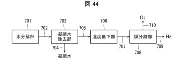
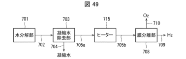
- a water decomposition unit that decomposes water with a photocatalyst to generate a gas containing hydrogen and oxygen, a condensed water removal unit that processes the gas from the water decomposition unit for condensed water removal, and a condensed water removal unit that removes condensed water.
- a hydrogen/oxygen production apparatus comprising a humidity lowering section for subjecting gas to humidity lowering treatment, and a membrane separation section for membrane separation of hydrogen and/or oxygen from the gas from the humidity lowering section.
- the hydrogen/oxygen production apparatus of [1] further comprising a gas-liquid separation unit into which the gas from the water decomposition unit is introduced, and in which the gas that has passed through the gas-liquid separation unit is introduced into the condensed water removal unit .
- a pipe is provided to guide the gas from the water decomposition unit to the condensed water removal unit, and the pipe is provided with a downward slope toward the water decomposition unit of [1] or [2]. Hydrogen and oxygen production equipment.
- a flame-extinguishing device including a flame-extinguishing device, wherein the flame-extinguishing device is installed between a first pipe to which raw gas is supplied from one end side and a second pipe arranged at an angle to it,
- the hydrogen/oxygen production apparatus according to any one of [1] to [5], wherein the flame extinguishing device has the following configurations (i) to (iii).
- a joint pipe section having a branch to a third pipe while flowing raw gas from the first pipe to the second pipe;
- a flame propagation suppressing portion provided between the connecting pipe portion and the first pipe and/or the second pipe, wherein the flame propagation suppressing portion includes a bent portion and a having a constricted portion and a porous portion;
- a pressure reducing section arranged at an angle intersecting the extension line of the traveling direction of the raw gas from the first pipe and arranged via the third pipe.
- a flame-extinguishing device including a flame-extinguishing device, wherein the flame-extinguishing device is installed between a first pipe to which raw gas is supplied from one end side and a second pipe, wherein the flame-extinguishing device has the following (The hydrogen/oxygen production apparatus according to any one of [1] to [5], having the configurations of 1) to (4).
- the connecting pipe portion when the gas circulating on the pipe side without the flame propagation suppressing portion (temporarily referred to as the first pipe side for the sake of explanation) is ignited and deflagration or detonation occurs, first, the connecting pipe portion Although there are two pipe directions and a third pipe direction, the second pipe direction has an angle other than 0° with respect to the first pipe direction. As a result, the second pipe and the first pipe are not linearly arranged. In the meantime, at the pressure reduction part on the extension line of the first pipe, the pressure is released or a reflected wave is generated, and the gas pressure inside the coupling pipe is practically reduced by the effect of phase interference etc. The flame propagation is suppressed by the flame propagation suppressing portion on the second pipe side.
- the flame propagation suppression unit will deflagrate and detonate first.
- complete extinction and pressure reduction are not necessarily realized.
- the momentum is further weakened by the branching, and the function of the pressure reducing section at the end of the third pipe realizes complete extinguishing and pressure reduction.
- the life of the photocatalyst is long. That is, since water dissolves many things, when a thick tube is used, the co-catalyst tends to flow out and be lost. Even if the co-catalyst of the photocatalyst is eluted, it has the property of being re-precipitated by light irradiation. Elution is inevitable.
- the amount of water by using a double pipe the amount of co-catalyst that flows out is reduced, and since the area where water flows is near the catalyst, re-precipitation is likely to occur. , the light conversion efficiency of the photocatalyst can be maintained high, and the life of the photocatalyst can be extended.
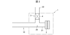
- FIG. 1 is a diagram schematically showing the configuration of a first example of a flame-extinguishing device according to an embodiment of the first gist of the present invention
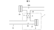
- FIG. 4 is a diagram schematically showing the configuration of a second example of the flame-extinguishing device according to the embodiment of the first gist of the present invention
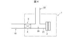
- Fig. 10 is a diagram schematically showing the configuration of a third example of the flame-extinguishing device according to the embodiment of the first gist of the present invention
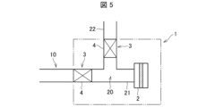
- FIG. 10 is a diagram schematically showing the configuration of a fourth example of the flame-extinguishing device according to the embodiment of the first gist of the present invention
- Fig. 10 is a diagram schematically showing the configuration of a fifth example of the flame-extinguishing device according to the embodiment of the first gist of the present invention
- FIG. 10 is a diagram schematically showing the configuration of a sixth example of the flame-extinguishing device according to the embodiment of the first gist of the present invention
- FIG. 11 is a diagram schematically showing the configuration of a seventh example of the flame-extinguishing device according to the embodiment of the first gist of the present invention
- FIG. 10 is a diagram schematically showing the configuration of a fourth example of the flame-extinguishing device according to the embodiment of the first gist of the present invention
- Fig. 10 is a diagram schematically showing the configuration of a fifth example of the flame-extinguishing device according to the embodiment of the first gist
- FIG. 11 is a diagram schematically showing the configuration of an eighth example of the flame-extinguishing device according to the embodiment of the first gist of the present invention
- FIG. 4 is a diagram schematically showing the configuration of a first example of a flame propagation suppressor according to an embodiment of the first gist of the present invention
- FIG. 6 is a diagram schematically showing the configuration of a second example of the flame propagation suppressing portion according to the embodiment of the first gist of the present invention
- FIG. 10 is a diagram schematically showing the configuration of a third example of the flame propagation suppressor according to the embodiment of the first gist of the present invention
- FIG. 4 is a diagram schematically showing the configuration of a first example of a flame propagation suppressor according to an embodiment of the first gist of the present invention
- FIG. 6 is a diagram schematically showing the configuration of a second example of the flame propagation suppressing portion according to the embodiment of the first gist of the present invention
- FIG. 10 is a diagram schematic
- FIG. 10 is a diagram schematically showing the configuration of a fourth example of the flame propagation suppressing portion according to the embodiment of the first gist of the present invention
- FIG. 10 is a diagram schematically showing the configuration of a fifth example of the flame propagation suppressor according to the embodiment of the first gist of the present invention
- FIG. 10 is a diagram schematically showing the configuration of a sixth example of the flame propagation suppressor according to the embodiment of the first gist of the present invention
- FIG. 11 is a diagram schematically showing the configuration of a seventh example of the flame propagation suppressor according to the embodiment of the first gist of the present invention
- FIG. 10 is a diagram schematically showing the configuration of a fourth example of the flame propagation suppressing portion according to the embodiment of the first gist of the present invention
- FIG. 10 is a diagram schematically showing the configuration of a fifth example of the flame propagation suppressor according to the embodiment of the first gist of the present invention
- FIG. 10 is a diagram schematically showing the configuration
- FIG. 12 is a diagram schematically showing the configuration of an eighth example of the flame propagation suppressor according to the embodiment of the first gist of the present invention
- FIG. 20 is a diagram schematically showing the configuration of a ninth example of the flame propagation suppressor according to the embodiment of the first gist of the present invention
- FIG. 20 is a diagram schematically showing the configuration of a tenth example of the flame propagation suppressor according to the embodiment of the first gist of the present invention
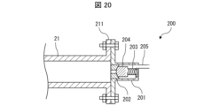
- FIG. 2 is a cross-sectional view schematically showing the configuration of a first example of a pressure reducing portion according to an embodiment of the first gist of the present invention
- FIG. 4 is a cross-sectional view schematically showing the configuration of a second example of the pressure reducing portion according to the embodiment of the first gist of the present invention
- FIG. 22 is a right side view schematically showing a side surface of the pressure reducing portion shown in FIG. 21
- FIG. 10 is a cross-sectional view schematically showing the configuration of a third example of the pressure reducing portion according to the embodiment of the first gist of the present invention
- FIG. 2 is a cross-sectional view schematically showing the configuration of an example of the buffering portion according to the embodiment of the first gist of the present invention
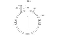
- FIG. 25 is a right side view schematically showing the side surface of the cushioning portion shown in FIG. 24
- 1 is a diagram schematically showing an experimental apparatus used in Examples 1-11.
- FIG. Fig. 2 is a diagram schematically showing the configuration of a first example of a flame-extinguishing device according to an embodiment of the second aspect of the present invention
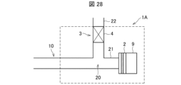
- FIG. 4 is a diagram schematically showing the configuration of a second example of the flame-extinguishing device according to the embodiment of the second aspect of the present invention
- Fig. 10 is a diagram schematically showing the configuration of a third example of the flame-extinguishing device according to the embodiment of the second aspect of the present invention
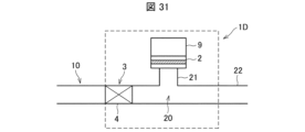
- Fig. 10 is a diagram schematically showing the configuration of a fourth example of the flame-extinguishing device according to the embodiment of the second aspect of the present invention
- FIG. 10 is a diagram schematically showing the configuration of a fifth example of the flame-extinguishing device according to the embodiment of the second aspect of the present invention
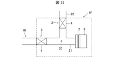
- FIG. 10 is a diagram schematically showing the configuration of a sixth example of the flame-extinguishing device according to the embodiment of the second aspect of the present invention
- FIG. 11 is a diagram schematically showing the configuration of a seventh example of the flame-extinguishing device according to the embodiment of the second aspect of the present invention
- FIG. 12 is a diagram schematically showing the configuration of an eighth example of the flame-extinguishing device according to the embodiment of the second aspect of the present invention
- FIG. 2 is a configuration diagram of a flame extinguishing device manufactured in an example according to an embodiment of the second gist of the present invention.
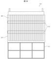
- Fig. 2 is a front view schematically showing the configuration of an example of a reaction device for photochemical reaction according to an embodiment of the third gist of the present invention;
- Fig. 2 is a side view schematically showing the configuration of an example of a reaction device for photochemical reaction according to an embodiment of the third aspect of the present invention;
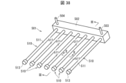
- Fig. 2 is a perspective view schematically showing an example of a manifold and tube assembly of a photochemical reaction reactor according to an embodiment of the third aspect of the present invention;
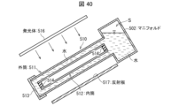
- FIG. 39 is an enlarged cross-sectional view taken along line II-II of FIG. 38;
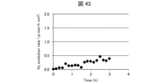
- FIG. 39 is a schematic cross-sectional view along line III-III in FIG. 38; 10 is a graph showing the results of Example 3-1.
- FIG. 10 is a schematic cross-sectional view of the device of Comparative Example 3-1; 10 is a graph showing the results of Comparative Example 3-1.
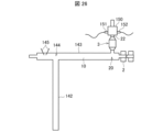
- Fig. 2 is a configuration diagram of a hydrogen/oxygen production apparatus according to an embodiment of the fourth aspect of the present invention; It is a block diagram of a membrane gas dryer.
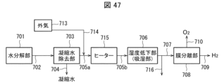
- Fig. 2 is a configuration diagram of a hydrogen/oxygen production apparatus according to an embodiment of the fourth aspect of the present invention;
- Fig. 2 is a configuration diagram of a hydrogen/oxygen production apparatus according to an embodiment of the fourth aspect of the present invention;
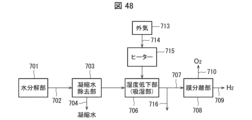
- Fig. 2 is a configuration diagram of a hydrogen/oxygen production apparatus according to an embodiment of the fourth aspect of the present invention;
- Fig. 2 is a configuration diagram of a hydrogen/oxygen production apparatus according to an embodiment of the fourth aspect of the present invention;
- the first gist of the present invention may be described as follows in this specification.
- gas circulation and "circulating gas” are sometimes used, but the gas in such a case can be any or all of combustible gas, combustion-supporting gas, inert gas, etc. in the system described later. It means that a gas containing Further, in some cases, liquid such as atomized water or droplet water may be entrained. Furthermore, the gas that circulates when deflagration or detonation occurs is not necessarily the gas that has the composition that initially flowed, but may become a gas that has been combined or decomposed as a result of a chemical reaction. , may be used as a generic term including these.
- normal time is sometimes used, in any mechanical equipment, chemical equipment, etc. where there is concern about explosions or detonations, gas generation, distribution, temporary retention, Storage refers to a safe and stable state.
- the expression “normal time” may be used regardless of whether the system is stopped or in operation.
- Detonation or “detonation generation” means that a gas that has the potential to cause deflagration or detonation when ignited actually ignites, deflagrates, and then, in some cases, detonates and generates a shock wave. However, in the series of reactions that also propagate the detonation flame, it refers to some or all of them. Used for both meanings.
- Hydrogen detonation gas refers to any composition of hydrogen-oxygen mixed gas in this specification unless otherwise specified, and even if it contains water vapor, etc., it is also described as hydrogen detonation gas.
- inside and outside may be used.
- inside the system means a portion of mechanical equipment or chemical equipment where combustible gas and mixed gas of combustible gas and combustion-supporting gas are generated, distributed, temporarily retained, stored, and consumed.
- Inside the system refers to the part where combustible gas and mixed gas of combustible gas and combustion-supporting gas are generated, distributed, temporarily retained, stored, and consumed in equipment equipped with the flame-extinguishing device of the present invention. include.
- Outside the system means the part other than that.
- the flame extinguishing device of the present invention can be used in all kinds of mechanical equipment, chemical equipment, etc. where there are concerns about explosions and detonations, and can be used for all combustible gases and mixed gases of combustible gases and combustible gases. Adaptable. INDUSTRIAL APPLICABILITY
- the flame extinguishing device of the present invention can be suitably used in chemical facilities in which hydrogen explosive fumes, in which hydrogen and oxygen coexist, which have particularly high explosive power, are generated, distributed, temporarily retained, and stored.
- the flame extinguishing device of the present invention can be suitably used for "hydrogen-oxygen generation and distribution equipment by electrolysis” or “hydrogen-oxygen generation and distribution equipment by photocatalyst” that further decomposes water to generate hydrogen and oxygen.
- the shock wave or detonation flame that occurs when it moves may damage equipment or cause serious secondary damage.
- the flame-extinguishing device of the present invention (also referred to as “extinguishing mechanism”) has the effect of a shock wave or detonation flame even when a pressurized stoichiometric hydrogen-oxygen mixed gas is ignited. can be effectively suppressed. For this reason, when hydrogen-oxygen is generated from water splitting by a photocatalyst, this flame-extinguishing mechanism can be appropriately arranged in various positions, such as around the photocatalytic reactor and around the hydrogen-oxygen separation membrane arranged in the subsequent stage. be.
- the flame extinguishing device of one embodiment of the present invention has the following three requirements as its configuration. 1st. a connecting pipe section having a branch to a third pipe while allowing raw gas from the first pipe to flow to the second pipe; Second. A flame propagation suppressing portion provided between the connecting pipe portion and the first pipe and/or the second pipe, and having a bent portion, a constricted portion, and a porous portion in the housing and the flow path in the housing; Third. A pressure reducing part arranged at an end of the third pipe which is not orthogonal to the extension line of the first pipe in the direction of movement of the raw gas.
- One embodiment of the present invention includes a first pipe to which raw gas is supplied from one end side, A flame extinguishing device installed between it and a second pipe arranged at an angle,
- the flame extinguishing device is characterized by having the following 1 to 3 parts, 1st. a connecting pipe section having a branch to a third pipe while allowing raw gas from the first pipe to flow to the second pipe;
- Second. A flame propagation suppressing portion provided between the connecting pipe portion and the first pipe and/or the second pipe, and having a bent portion, a constricted portion, and a porous portion in the housing and the flow path in the housing;
- Third. A pressure reducing part arranged at an end of the third pipe which is not orthogonal to the extension line of the first pipe in the direction of movement of the raw gas.
- the flame extinguishing mechanism of the present invention is expected to have the effect of mitigating shock wave propagation to the second pipe and the effect of suppressing flame propagation when the first pipe is ignited.
- the flame extinguishing mechanism of the present invention has the effect of mitigating the shock wave to the pipe portion or the first pipe and the effect of suppressing the spread of flame even if the second pipe is ignited. It is also possible to configure to have both.
- FIG. 1 is a diagram schematically showing the configuration of a photochemical reaction plant 100 according to this embodiment.
- the photochemical reaction plant 100 includes a photochemical reaction device 110, a condensed water removal device 120, a humidity reduction device 130, a separation membrane device 140, a flame extinguishing device 160 and a vacuum pump 170.
- the photochemical reaction device 110 has a photochemical reaction reactor.
- a photochemical reaction reactor is a reactor that performs a photochemical reaction.
- a photochemical reaction is, for example, a reaction that produces a high-energy substance from a liquid in the presence of light.
- One example is a reaction that produces hydrogen gas and oxygen gas from water in the presence of a photocatalyst. The present invention will be described in more detail below based on an example of producing hydrogen gas and oxygen gas from water.
- the condensed water removal device 120 is a device that removes condensed water in the gas from the reaction device 110 for photochemical reaction.
- the condensed water removal device 120 may be appropriately arranged in the ventilation path of the gas from the photochemical reaction device 110, and may be arranged for each photochemical reaction device 110. , or upstream of the separation membrane device 140 .
- Examples of condensate removal devices 120 include drain traps and gas traps.
- examples of the condensate removal device 120 may include a chiller that condenses water vapor in the raw gas by cooling.
- the condensed water removal device 120 condenses water vapor contained in the gas generated by the photochemical reaction device 110 to obtain condensed water.
- the condensed water removal device 120 may further have a configuration, such as a siphon, for automatically discharging the collected condensed water.
- the humidity lowering device 130 is a device that lowers the humidity of the gas.
- the humidity reduction device 130 is typically located downstream of the condensate removal device 120 and serves to reduce the humidity of the decondensed gas.
- Examples of the humidity reducing device 130 include a moisture adsorption tower having a moisture absorbing material such as silica gel, a membrane gas dryer, and a water vapor selective permeation tube described in JP-A-2017-213477.
- examples of the humidity reduction device 130 may include a device, such as a heater (eg, a heat exchanger), that raises the temperature of the gas to relatively reduce the humidity.
- the humidity reducing device 130 reduces the humidity of the gas from which the condensed water removing device 120 has removed the condensed water by reducing the moisture content of the gas.
- the separation membrane device 140 is a device that separates hydrogen and oxygen from the gas generated by the photochemical reaction device 110 .
- the separation membrane device 140 may be any device that can separate a specific component from the gas.
- the separation membrane device 140 may normally be arranged at the most downstream position in the gas flow path in the photochemical reaction plant 100, but may be arranged at a position further upstream, and a plurality of separation membrane devices may be arranged. good too.
- Examples of the separation membrane device 140 include known devices having hollow fiber membranes or zeolite membranes as separation membranes. Separation membrane device 140 membrane separates hydrogen and/or oxygen from the gas from humidity reduction device 130 .
- the flame extinguishing device 160 is a device that reduces the propagation of flames that occur when an explosion or detonation occurs.
- the flame extinguishing devices 160 are suitably arranged at multiple locations in the gas flow path, for example, so that the flame propagation affects only a more limited area in the photochemical reaction plant 100 . A specific description of the flame-extinguishing device 160 will be given later.
- the vacuum pump 170 is a device for generating a pressure difference for a specific gas to pass through the separation membrane in the separation membrane device 140 .
- FIG. 1 shows an example of the basic configuration of the flame extinguishing device.
- the flame extinguishing device 1 is installed between the first pipe 10 to which the raw gas is supplied and the second pipe 22 .
- the first pipe and the second pipe are not connected straight, but arranged at an angle other than 0°.
- the extension line of the first pipe and the extension line of the second pipe are not connected straight but intersect at an angle other than 0°.
- first pipe and the second pipe may be an integral body including a pipe connection portion therebetween, or the first pipe, the second pipe, and the pipe connection portion may be independent members that can be connected to each other. good.
- the flame-extinguishing device 1 includes a connecting pipe portion 20 connected to the first pipe 10 and the second pipe 22 to which the raw gas is supplied and the further third pipe 21, and the second pipe when viewed from the connecting pipe portion 20.
- the flame propagation suppression unit 3 having a porous portion through which the raw gas flows, and the pressure reduction unit arranged at the end of the third pipe 21 to reduce the internal pressure when the internal pressure of the third pipe 21 rises. a part 2;
- the third pipe 21 is not perpendicular to the first pipe 10 .
- this device if a fire is ignited on the first pipe side, a shock wave propagation mitigation effect and a flame propagation suppression effect are expected in the second pipe or further downstream thereof.
- this flame-extinguishing device is installed in a so-called "artificial photosynthesis plant", which is a facility for generating and distributing hydrogen and oxygen using a photocatalyst. A case where the first pipe is ignited will be described as an example.
- the shock wave and the flame after the detonation transition will propagate from the first pipe side.
- the shock waves and detonation flames that reach the flame extinguishing device propagate in all directions, but because they tend to propagate in a straight line, they are not perpendicular to the extension line of the raw gas traveling direction in the first pipe.
- the pressure reducing section arranged at the end of the third pipe is easily reached.
- the present inventors have discovered from experimental and theoretical studies that reducing the pressure is an important prerequisite. Therefore, the pressure is effectively reduced by various methods described later in the pressure reduction section.
- flame spread suppression requires a suitable flame spread suppressor.
- the flame spread suppression section is coupled to the pressure reduction section via a coupling piping section having one or more branches.
- the flame propagation suppressing section is arranged so as to flow the gas in a direction perpendicular to it, for example, 90 degrees. That is, it is arranged in a direction different from the direction in which the shock wave or detonation flame propagates relatively easily (that is, in the straight-ahead direction).
- the flame propagation suppression effect of the flame propagation suppressing portion can be effectively exhibited while the detonation pressure is reduced, and it is possible to prevent the propagation of the shock wave and the flame caused by the detonation to the second pipe.
- the flame propagation suppression unit includes a housing capable of mounting an internal structure, and at least includes the following configuration. That is, in the case of having a housing, gas is circulated in the housing, and a constricted portion that is narrower than the surrounding piping etc., and a porous body such as a metal sintered body or a ceramic sintered body It is preferable that the porous portion containing and the bent portion for changing the direction of the flame are included as a structural unit.
- flame propagation suppression involves intricately bending the flow path inside it, constricting (narrowing) the flow path using the flame escape distance as a guideline, and incorporating multiple mechanisms that prevent the flame from traveling straight.
- the flame propagation suppressing portion further includes the constricted portion described above, and it is even more preferable that it further includes a bent portion.
- the flame propagation suppression section, the coupling pipe section, and the pressure reduction section can effectively suppress the propagation of the shock wave and the detonation flame by combining them.
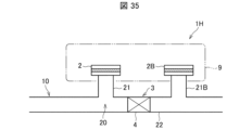
- FIG. 3 is an example of this, in which two pressure reduction sections 2 and 2A are arranged for one flame propagation suppressing section in order to extend the effects that can be achieved with the configuration of FIG.
- the shock wave propagation mitigation effect to the opposite side and the flame A propagation suppression effect is expected, and the function of each element is as described in the basic configuration of FIG. In FIG.
- the configuration on the lower side of the drawing is illustrated as a basic flame extinguishing device of the present invention, but the configuration on the upper side of the drawing (configuration including the connecting pipe section 20A, the flame propagation suppressing section 3 and the pressure reducing section 2A) is It can also be regarded as a basic fire extinguishing device.
- Fig. 4 shows the case where the flame propagation suppression part is provided on the first pipe side. That is, in the example of FIG. 4, the flame propagation suppressing portion 3 is provided on the first pipe side when viewed from the connecting pipe portion. In the example of FIG. 4, when ignition occurs on the first pipe side in the same way as before, the shock wave and the detonation flame reach the flame propagation suppressing portion first.
- the flame propagation suppressing section has at least the following configuration as described above. That is, a housing capable of mounting an internal structure, a flow path that allows gas to flow within the housing and is narrower than the surrounding pipes, etc., and a porous material such as a sintered metal It contains a porous part containing a body as a structural unit.
- the flame that has passed through here and has lost its momentum will drop in pressure if it is released from the pressure reduction section, and if it is not released, it will be overlapped with the reflected wave from the pressure reduction section, etc., and will reach the second pipe side. It will not proceed and the flame will be suppressed.
- Fig. 5 is an example in which the flame propagation suppressing portion is double arranged in Figs. 2 and 4 . That is, the example of FIG. 5 includes the flame propagation suppressing portions 3, 3 on the first pipe side and the second pipe side, respectively, when viewed from the connecting pipe portion.
- the shock wave propagation suppression effect and flame propagation to the opposite side A suppression effect is expected, and the function of each element is as described above.
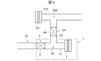
- FIG. 6 shows an enhanced configuration of the flame-extinguishing device of the present invention, which can achieve even stronger flame-extinguishing performance.
- FIG. 6 the configuration similar to that in FIG. 4 arranged on the lower side of the figure is illustrated as the flame extinguishing device of the present invention, but the configuration similar to that of FIG. It is possible.
- FIG. 7 in the flame extinguishing device having the same configuration as in FIG. 5, a fourth branch pipe is additionally arranged in the connecting pipe portion, and the pressure reducing portion 2A is additionally arranged at the tip thereof. is also possible.
- a buffer section capable of accommodating substances flowing out from the pressure reducing section, and relatively high-temperature and relatively high-pressure gas discharged from the pressure reducing section and reaction products and particles contained therein are provided. may be prevented from scattering to the surroundings.
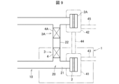
- FIG. 9 the embodiment of FIG. 2 is double combined, and buffer portions 41 and 42 are provided in the pressure reducing portions 2 and 2A, respectively.
- Diluent gas distribution pipes 43 and 45 are connected to the buffer portions 41 and 42, respectively.
- a diluent gas distribution pipe 44 is provided so as to communicate the insides of the buffer portions 41 and 42 .
- the configuration on the lower side of the figure is illustrated as the basic flame extinguishing device in the present invention, but it is also possible to regard the configuration on the upper side in the figure as the basic extinguishing device in the present invention.
- diluent gas nitrogen, rare gas, air, carbon dioxide, or a mixed gas of these can be used.
- the diluent gas is passed through the pipes 43, 44, 45 in order or in the opposite direction.
- the joint pipe part in the present invention is a part having a branch to the third pipe at the same time as flowing the raw gas from the first pipe to the second pipe. That is, the connecting pipe portion is a portion that connects the first and second pipes to which the raw gas is supplied and the further third pipe.
- the gas flow from the first pipe and the gas flow to the second pipe that is, the first pipe is extended in the normal gas flow direction, and the second pipe is opposite to the normal gas flow direction.
- the value on the smaller side of the angle formed by these two straight lines when extended in the direction of is important.
- This angle is preferably 30 degrees or more, preferably 60 degrees or more, particularly preferably 75 degrees or more, and most preferably 90 degrees, ie perpendicular. If the angle is 90 degrees or more, the angle becomes shallow when viewed from the opposite direction, so 90 degrees is most preferable.
- the second pipe and the first pipe can be arranged in parallel if the connecting pipe in the fire extinguishing device is bent twice at the same angle in opposite directions. can also be used as a connecting tubing section.
- the sum of the absolute values of the curved portions is preferably 60 degrees or more, particularly preferably 75 degrees or more, and more preferably 90 degrees or more.
- the pipe cross section of the connecting pipe portion has no corners, preferably approximately elliptical or approximately circular, more preferably approximately circular, and most preferably circular. This structure is preferable from the viewpoint of increasing pressure resistance.
- This flame extinguishing device can suppress flame propagation due to explosions, detonations, etc., and is effective in suppressing equipment damage and preventing secondary damage.
- the flame-extinguishing device as a whole needs to have high explosion-proof performance.
- pipes with a cylindrical cross-section and spherical gas storage tanks are more resistant to pressure and resistance than pipes with a rectangular cross-section and rectangular parallelepiped tanks, even if the pipe thickness and tank thickness are the same. Explosive performance can be improved. Therefore, the cross-section of the piping constituting the present fire extinguishing device is preferably substantially elliptical or substantially circular, more preferably substantially circular, and most preferably circular.
- the cross-sections of the flame propagation suppressing portion and the pressure reducing portion are preferably substantially elliptical or substantially circular, more preferably substantially circular, and most preferably circular.
- approximately circular here means circular except for manufacturing errors, slight deformation during on-site installation, and slight deformation due to welding, etc. during repair.
- the pressure resistance P (tube) (MPa (G)) of the piping is preferably 2 MPa (G) or more, and is 4 MPa (G) or more, so as to withstand pressure fluctuations at the time of intense shock waves and detonation. is more preferably 8 MPa (G) or more, and most preferably 16 MPa (G) or more.
- the upper limit is preferably 30 MPa (G) or less, more preferably 27.5 MPa (G) or less, further preferably 25 MPa (G) or less, and 22.5 MPa (G). Most preferably:
- the pressure resistance P (tube) (MPa (G)) of the coupling pipe portion satisfies the following equation. 2 ⁇ P(tube) ⁇ 30
- the pressure resistance is obtained from a normal pressure resistance test of the piping according to the material.
- the piping be able to withstand normal generation of raw gas as well as during detonation.
- piping that is strong enough for normal use tends to be generally detonation-resistant in the present invention. This is thought to be because the detonation occurs in a very short period of time, on the order of milliseconds, and therefore it is difficult for specific portions of the piping to be subjected to an external force that would cause damage due to the detonation.
- the flame suppression device of the present invention is provided with at least one flame propagation suppressor.
- the flame propagation suppressing section may include a housing and a flow path inside the housing, have a porous section through which the raw gas flows, and may further have a bent section and a constricted section. That is, the flame propagation suppression unit further has a housing through which the raw gas flows through the first pipe and/or the second pipe, and the housing includes a bent portion, a constricted portion and a porous portion therein.
- the pressure resistance of the flame propagation suppressing portion is preferably 0.5 MPa (G) or more, more preferably 1 MPa (G) or more, further preferably 2 MPa (G) or more, and 4 MPa (G). It is most preferable that it is above. However, if the pressure resistance and explosion resistance performance are excessively increased, the thickness of the housing becomes excessively thick, resulting in excessive weight and excessive cost. For this reason, the upper limit is preferably 25 MPa (G) or less, more preferably 20 Pa (G) or less, further preferably 15 MPa (G) or less, and 10 MPa (G) or less. is most preferred.
- the material of the flame propagation suppressing portion As the material of the flame propagation suppressing portion, a material capable of achieving both pressure resistance and thermal conductivity is preferable, and a metal material or a composite material containing a metal material is preferable. More preferably, the housing contains a metal material, that is, the housing is made of metal, and iron-based materials or stainless steel materials are even more preferable. Note that different materials may be used depending on the location of the housing.
- the shape of the housing is preferably cylindrical, and by adopting such a shape, it is possible to improve the pressure resistance and explosion resistance performance, as with other piping.
- the bent portion in the housing greatly changes the direction of propagation of the flame, and may include a U-shaped or L-shaped bend, a T-shaped or cross-branched portion, or the like. Since the flame has straightness, by doing so, it is possible to further improve the flame propagation suppressing function. It is preferable to provide a plurality of bent portions in the flow path inside the housing, and it is possible to realize the bent portions in the form of a pipe or a shape embedded in the housing. In addition, it is also possible to realize the bent portion by filling with appropriate particles, porous material, or the like, which will be described later. In particular, bent portions realized by filling particles, porous bodies, or the like repeatedly bend, bend, branch, and integrate at random from the viewpoint of the flow path, and are more preferable from the viewpoint of flame propagation suppression.
- the cross-sectional area of the constricted portion in the housing in the flame propagation suppressing portion of the present invention is smaller than any of the cross-sectional areas of the first pipe, the second pipe, and the connecting pipe. preferable. This is to effectively suppress flame propagation in the flame propagation suppressing portion. Therefore, the cross-sectional area of the constricted flow path (portion) in the housing is preferably 80% or less, more preferably 60% or less, and 40% or less of the cross-sectional area of each of the other piping portions. More preferably, it is most preferably 20% or less. On the other hand, if the cross-sectional area of the narrowed portion in the housing becomes excessively small, the pressure loss during normal gas flow becomes excessive.
- the cross-sectional area is preferably 3% or more, more preferably 5% or more, still more preferably 10% or more, and most preferably 15% or more. If the diameters of the first pipe, the second pipe, and the joint pipe are different, this average may be used as a reference.
- the width (also referred to as “diameter”) of the constriction in the housing is preferably 4.5 mm or less, more preferably 4 mm or less, even more preferably 3.5 mm or less, and 3 mm or less. is most preferred.
- the diameter of the narrowed portion is preferably 0.3 mm or more, more preferably 0.4 mm or more, still more preferably 0.5 mm or more, and most preferably 0.6 mm or more. That is, the diameter of the constricted portion in the housing is selected so as to exhibit a sufficient flame propagation suppressing function while preventing excessive pressure loss during normal times when detonation or the like does not occur. It is preferable that the diameter of the constricted portion is selected while considering the balance with the pressure loss, especially with reference to the flame escape limit value of the combustible gas.
- the width (diameter) of the constricted portion in the housing does not need to be uniform within the flow path, and is selected to be approximately 0.3 mm in a certain portion so as to achieve sufficient flame propagation suppression. It is also possible to expand the width to about 4.5 mm at other locations to emphasize the effect of reducing pressure loss.
- the diameter of the constricted portion is the distance between the wall surfaces of the channel at the narrowest portion in the gap through which the raw gas flows.
- the constriction may be the above-mentioned gap having a length or width of the above-mentioned specific diameter and a wider width or width.
- a funnel-shaped or conical structure can be considered as an example of the constriction.
- the shape of the flame propagation-suppressing porous portion can be any shape in accordance with the shape of the housing, the constricted flow path in the housing, and the like.
- the housing is cylindrical, and the narrowed flow path in the housing on the side of the first pipe is concentrated in the upper part of the housing, while a similar narrowed flow path structure in the housing on the side of the second pipe is formed in the housing.
- the porous body constituting the porous portion may be arranged in a cylindrical shape along the housing in the meantime.
- the cylindrical porous portion may be a packed layer formed by filling a circular tube with particles.
- porous body is a substantially cylindrical porous body having a substantially cylindrical inner space penetrating vertically at the center in the diametrical direction, that is, a porous body having a substantially cylindrical porous portion. is more preferably employable.
- the planar shape of the upper and lower surfaces is approximately donut-shaped.
- shock waves or pressure fluctuations are propagated from the outside of the porous body (from the outside of the donut shape in plan view), and flames are also made to enter from this direction, and then It is also preferable to dispose so as to circulate in the substantially cylindrical inner space of the porous body (the inside of the donut shape in plan view). In this way, the pressure resistance and detonation resistance of the porous body are improved compared to the case of reverse flow (that is, shock waves or pressure fluctuations enter from the inside of the donut shape in plan view and flow outside).
- the porous body is relatively strong against compressive impact, but weak against tensile impact.
- the circulating gas flows from the outside of the cylindrical porous body (the outside of the donut shape in a plan view) to the inner space (the inside of the donut shape in a plan view). Become.
- the gas flows randomly through the connected void portions in the porous body.
- any material such as metal, ceramic, or composite material thereof can be selected as the material of the porous body.
- metals include Fe, Ni, Ti, Cr, Mo, Si, Al, Mg, etc., and alloys containing elements selected from these may be used.
- ceramic materials Al 2 O 3 -based materials, SiO 2 -based materials, SiC-based materials, ZrO 2 -based materials, etc. can be listed.
- the porous material is preferably made of metal because of its high thermal conductivity and stability. Furthermore, among them, it is preferable that the melting point is relatively high, that it is stable in contact with a detonation flame, and that the porous shape, particularly the pore size described later, can be maintained.
- SUS304 which is a stainless steel material that is an alloy containing Fe, Ni, Cr, etc.
- SUS316 which is a stainless steel material containing Mo.
- SUS316L which has a reduced amount of C, is more preferable. This is because the water resistance and corrosion resistance are improved.
- the "holes" that are intentionally formed in the porous body having voids through which the gas flowing through the narrow flow path in the housing can pass can be formed by any method. However, rather than a "straight hole” that can be formed by laser processing, etc., various types of unsintered parts formed during sintering that can be formed by high-temperature pressure treatment of powders of ceramics, metals, etc. Randomly sized pores (pores, also referred to as “voids”) are preferred. By doing so, the effect of suppressing flame propagation can be improved.
- These random pores can be made smaller in size and the number per unit volume can be reduced by increasing the degree of sintering. It is important to set it so that it is difficult to propagate. It is preferable that the pores have a longitudinal width of 0.50 ⁇ m or more and 2.45 ⁇ m or less. Such "minimal holes" are particularly effective in suppressing the propagation of detonation flames such as hydrogen detonation gas.
- the porous body also has relatively large pores (referred to as medium pores) of 50 ⁇ m or more and 100 ⁇ m or less. These "micropores” and “middle pores” can remain as unsintered portions during sintering, and most of them are randomly bent, curved, and branched to the surface of the porous body. , integration, etc. are repeated. Such a configuration is preferable because it can exhibit a large flame propagation suppressing function within a moderate pressure drop.
- the density is preferably 90% or less, more preferably 80% or less, further preferably 70% or less, further preferably 60% or less compared to the bulk material. Most preferably: Also, it is preferably 10% or more, more preferably 20% or more, still more preferably 30% or more, and most preferably 40% or more.
- FIGS. 10 to 17 are assumed to be installed in the second pipe 22, and are made of metal such as SUS or brass. Also, the porous body is a metal sintered body.
- FIG. 10 is a diagram schematically showing the configuration of a first example of the flame propagation suppressing section according to the present embodiment.
- the flame spread suppression section 300 includes a housing 301 , baffle plates 302 and porous bodies 303 .
- the housing 301 has a cylindrical peripheral wall and both ends, and both ends are connected to the second pipe 22 .
- the inside of the housing 301 and the second pipe 22 are connected as shown in the cross-sectional shape of the A portion that is one end of the housing 301 and the cross-sectional shape of the E portion that is the other end of the housing 301. are in communication.
- a plurality of baffle plates 302 are arranged on one end side in the axial direction of the housing 301, and a porous body 303 is arranged on the other end side.
- the baffle plate 302 has a notch portion in which a part of a circular arc is cut in a straight line, as shown in the cross-sectional shape of the B portion near one end of the housing 301 and the cross-sectional shape of the C portion near the center. It has a substantially circular planar shape.
- the baffle plates 302 are arranged so that the cutout portions of adjacent baffle plates 302 do not overlap in the axial direction.
- a gap formed by the cutout portion of the baffle plate 302 and the adjacent baffle plate 302 forms a bent portion in the flow path of the raw gas.
- the gap between the baffle plates 302 adjacent in the axial direction or the notch portion of the baffle plate 302 communicating with the gap forms a narrowed portion in the flow path of the raw gas.
- the porous body 303 is arranged adjacent to the other end of the housing 301, and is a cylindrical porous body as shown in the cross-sectional shape of the D section near the other end of the housing 301.
- the diameter of the porous body 303 is slightly smaller than the inner diameter of the housing 301, and the gap between the outer peripheral surface of the porous body 303 and the inner peripheral surface of the housing 301 serves as a raw gas flow path.
- a large number of holes are continuous in the porous body 303, and the holes serve as flow paths for the raw gas, which communicate the inside of the housing 301 and the above-described piping on the other end side.
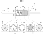
- FIG. 11 is a diagram schematically showing the configuration of a second example of the flame propagation suppressing section according to the present embodiment.
- a flame propagation suppressing portion 310 shown in FIG. 11 has substantially the same configuration as the flame propagation suppressing portion 300 of FIG.
- the screw 312 is fixed to one end inside the housing 301 as shown in the cross-sectional shape of the B portion near one end of the housing 301 and the cross-sectional shape of the C portion near the center. to the porous body 303 to form a spiral space.
- the spiral space forms a bend.
- the screw 312 forms a space that narrows from the gap between one end of the screw 312 and the inner wall surface of the housing 301 to the gap between the parallel blade plates of the screw 312, and the space is a narrowed portion. .
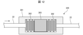
- FIG. 12 is a diagram schematically showing the configuration of a third example of the flame propagation suppressing section according to the present embodiment.
- the flame propagation suppression unit 320 shown in FIG. 12 has a porous body 303 in the central part of the housing 301, and has a plurality of baffle plates 302 at both ends of the housing 301. It has substantially the same configuration as the propagation suppression unit 300 .
- the plurality of baffle plates 302 are arranged so that the cutout portions of adjacent baffle plates 302 do not overlap in the axial direction, as described above.
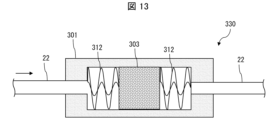
- FIG. 13 is a diagram schematically showing the configuration of a fourth example of the flame propagation suppressing section according to the present embodiment.
- the flame propagation suppressor 330 shown in FIG. 13 has a porous body 303 in the central portion of the housing 301, and has screws 312 at both ends of the housing 301, respectively. It has substantially the same configuration as the suppression unit 310 .
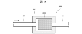
- FIG. 14 is a diagram schematically showing the configuration of a fifth example of the flame propagation suppressing section according to the present embodiment.
- 14 does not have a baffle, and the porous body 303 extends from the other end of the housing 301 to one end. It has substantially the same configuration as the part.
- the porous body 303 forms a circular first gap that spreads outward in the circumferential direction from the pipe at one end in the housing 301, and extends from one end to the other end in the housing 301.
- a cylindrical second gap is formed with the inner peripheral surface.
- the first gap forms a bend that bends from the pipe.
- the second gap forms a bent portion bent from the first gap.
- the first gap forms a flow path that narrows in width from the pipe, forming a narrowed portion.
- FIG. 15 is a diagram schematically showing the configuration of a sixth example of the flame propagation suppressing section according to the embodiment of the present invention.
- the second pipe 22 is located not in the central part of the housing 351 but in the peripheral part as shown in the cross-sectional shape of the A part and the E part which are the end parts of the housing 351.
- a connecting plate 352 is provided in place of the baffle plate 302 and is in contact with the end surface of the porous body 303, as shown by the connection points and the cross-sectional shapes of the B and D portions near the end of the housing 351. It has substantially the same configuration as the flame propagation suppressing portion 320 of FIG.
- the communication plate 352 is a disk having the same diameter as the inner diameter of the housing 351, and has a communication hole 354 having a circular opening shape on the peripheral edge.
- the communication plate 352 is arranged inside the housing 351 so that the position of the communication hole 354 does not overlap the second pipe 22 connected to the housing 351 in the axial direction.
- the gap between the communicating plate 352 and the end of the housing 351 forms a bent portion that bends from the pipe, and the communicating hole 354 forms a bent portion that bends from the gap at the end of the housing 351 to the communicating hole. ing.
- the communicating hole 354 forms a constricted portion that narrows from the gap to the communicating hole 354 .
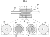
- FIG. 16 is a diagram schematically showing the configuration of a seventh example of the flame propagation suppressing section according to the embodiment of the present invention.
- the flame propagation suppressing portion 360 shown in FIG. 16 has the same structure as that of FIG. It has substantially the same configuration as the section 340 .
- the porous body 363 has a columnar space in its center that communicates with the pipe on the other end side.
- the piece portion 365 has a disc portion 366 and a shaft portion 367 .
- the disk part 366 has a thickness that forms a gap with one end of the housing 301 .
- the disk portion 366 has the same diameter as the porous body 363, as shown in the cross-sectional shape of the B portion near one end of the housing 301, and forms a gap between the outer peripheral portion and the housing 301. are doing.
- the shaft portion 367 is a columnar bar with a smaller diameter than the space at the center of the porous body 363 as shown in the cross-sectional shape of the center portion C of the housing 301 .
- the gap formed at one end of the housing 301 by the disc portion 366 forms a bent portion that bends from the second pipe 22, and also forms a constricted portion that narrows the width of the flow path from the second pipe 22. ing. Further, the gap at the one end and the gap on the outer peripheral side of the disc portion 366 communicating therewith form a bent portion that bends from the gap at the one end.
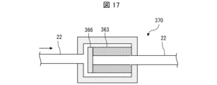
- FIG. 17 is a diagram schematically showing the configuration of an eighth example of the flame propagation suppressing section according to the embodiment of the present invention.
- a flame propagation suppressing portion 370 shown in FIG. 17 has substantially the same configuration as the flame propagation suppressing portion 360 of FIG. 16 except that the shaft portion 367 is not provided.
- the flame propagation suppressing section preferably has a mechanism for cooling the housing.
- Cooling of the housing may be natural air cooling, and air cooling is preferable because the flame propagation suppressing section can be configured simply.
- a configuration in which forced air cooling is performed using a blower or the like can improve the heat dissipation of the housing, and thus can be preferably adopted from the viewpoint of improving the quenching performance.
- water-cooling the housing of the flame propagation suppressing unit can further improve the heat dissipation of the housing, so that further improvement in flame-extinguishing performance can be expected, and can be adopted more preferably.
- the exterior portion of the housing of the flame propagation suppression unit has a pipe through which cooling water can flow.
- the exterior shape of the housing is preferably a shape that increases the surface area from the viewpoint of ensuring heat dissipation, and more preferably a shape that has heat radiating fins or the like.
- a configuration that attempts to reduce the temperature of the flame entering the flame propagation suppressing section depending on the internal configuration.
- a flame propagation suppressing portion such as the top portion described above
- a block-shaped or plate-shaped metal member or the like is arranged in the direction of propagation of the flame, and the flame is thinned, and the metal member and the It is also preferable to have a configuration in which heat is radiated by both the housing of the flame propagation suppressing section and the temperature of the flame is reduced.
- FIG. 18 is a diagram schematically showing the configuration of a ninth example of the flame propagation suppressing section according to the embodiment of the present invention.
- a flame propagation suppressor 380 shown in FIG. 18 has a configuration similar to the flame propagation suppressor 360 shown in FIG.
- a flame propagation suppressor 380 in FIG. 18 has a housing 381 , a porous body 383 and a top portion 385 .
- the porous body 383 is a sintered body of metal, and the rest are made of metal such as SUS or brass.
- the housing 381 has a first cylindrical portion 388 with a larger diameter located on one end side and a second cylindrical portion 389 with a smaller diameter located on the other end side.
- the porous body 383 is arranged on the other end side (inside the second cylindrical portion 389 ) inside the housing 381 .
- the porous body 383 has a cup-like shape with a cylindrical hole in the center of the cylindrical body.
- the top portion 385 is composed of a disc portion 386 and a shaft portion 387 .
- the disk portion 386 has a diameter slightly smaller than the inner diameter of the first cylindrical portion 388 .
- the shaft portion 387 is a columnar bar and has a length slightly shorter than the depth of the hole in the porous body 383 .
- a gap between one end of the first cylindrical portion 388 and the disk portion 386 forms a bent portion bent from the second pipe 22 .
- the gap also serves as a narrowed portion where the width of the raw gas flow path narrows from the width of the pipe.
- the gap between the inner peripheral surface of the first cylindrical portion 388 and the outer peripheral surface of the disk portion 386, the gap between the other end surface of the first cylindrical portion 388 and the disk portion 386, and the inner circumference of the second cylindrical portion 389 The boundaries between adjacent gaps in the gap between the surface and the outer peripheral surface of the porous body 383 are also bent parts that change the traveling direction of the raw gas.
- the gap between the peripheral surface of the hole of the porous body 383 and the peripheral surface of the shaft portion 387 of the top portion 385 also serves as a bent portion that directs the advancing direction of the raw gas toward the other end portion.
- the flame F that reaches the flame propagation suppressing portion 380 collides with the disk portion 386 and spreads in the radial direction.
- the size of the gap can be set based on the flame escape limit value (maximum safe gap) determined by the explosion class corresponding to the gas type, thereby preventing the flame F from propagating.
- the size of the gap in the flame propagation suppressing portion can be set based on the flame escape limit value (maximum safe gap) as described above.
- the top portion 385 absorbs part of the heat of the flame F
- the housing 381 absorbs part of the heat of the flame F and releases it to the outside. Since the housing 381 has a wider outer surface compared to the overall cylindrical form, it is easier to release heat, and a further cooling effect during flame propagation is expected.
- FIG. 19 is a diagram schematically showing the configuration of a tenth example of the flame propagation suppressing section according to the embodiment of the present invention.
- the flame propagation suppressing portion 390 shown in FIG. 19 has two of the flame propagation suppressing portions 380 shown in FIG. 386 are connected so as to face the downstream side.
- the flame propagation suppression unit 390 of FIG. 19 exhibits the same functions and effects as those of the flame propagation suppression unit 380 of FIG. 18 with respect to the flame F propagating from either upstream or downstream direction.
- the pressure reducing part has a function to reduce shock wave pressure propagating in the pipe, direct and indirect pressure fluctuation accompanying deflagration or detonation, pressure fluctuation due to unexpected excessive chemical reaction, etc.
- Various forms can be selected.
- the pressure reducing part is arranged at the end of the third pipe which is not orthogonal to the extension of the first pipe in the direction of movement of the raw gas.
- the pressure reducing part is arranged on the extension line of the normal traveling direction of the raw gas in the first pipe so as to face each other. is preferably arranged. Most preferably, the pressure reduction section is arranged so as to face the traveling direction from the front. In the case of such an arrangement, and considering the arrangement of the second pipe as described above, it is most preferable that the connecting pipe portion has a T-shaped configuration.
- the third pipe in which the pressure reduction section is arranged according to one aspect of the present invention is not perpendicular to either the first pipe or the second pipe.
- the angle having the smaller value is It is preferably 75° or less, more preferably 50° or less, still more preferably 30° or less, even more preferably 15° or less, and most preferably 0°. That is, in this case, the pressure reduction section faces the first pipe directly on an extension line of the direction in which the raw gas travels in the normal state.
- the pressure reducing section is arranged at the end of the third pipe, and is configured to reduce the internal pressure of the third pipe when the internal pressure of the third pipe increases.
- One form of the pressure reduction unit is the case of using a so-called safety valve. automatically return to the closed state. Therefore, in some cases, it can be used in a limited manner when pressure fluctuations and the like are assumed to be relatively small.
- the minimum pressure P (release) (MPa (G)) released to the outside of the system is preferably 0.1 MPa (G) or more, more preferably 0.2 MPa (G) or more, and 0.3 MPa ( G) or more is more preferable, and 0.4 MPa (G) or more is most preferable. This is because it may be dangerous to inadvertently release combustible gas or the like circulating in the system to the outside of the system when the pressure fluctuates excessively small. On the other hand, when using such a simple method, excessively high minimum opening pressure should be avoided from the viewpoint of ensuring safety.
- the upper limit of the minimum opening pressure is preferably 0.98 MPa (G) or less, more preferably 0.9 MPa (G) or less, further preferably 0.8 MPa (G) or less, Most preferably, it is 0.7 MPa (G) or less.
- FIG. 20 shows an example of a pressure reducing part that is a reversible pressure release device.
- FIG. 20 is a cross-sectional view schematically showing the configuration of the first example of the pressure reducing portion according to the embodiment of the invention.
- FIG. 20 shows an embodiment in which the pressure reducing portion is a relief valve.
- the safety valve 200 is attached to the flange 211 located at the end of the third pipe 21 with bolts and nuts.
- the safety valve 200 includes a valve seat 202 having a through hole communicating between the third pipe 21 and the valve chamber 201, a valve element 204 biased by a spring 203 toward the valve seat 202 in the valve chamber 201, a valve chamber 201 and a communication pipe 205 for communicating with the outside.
- the spring 203 contracts, and the inside of the third pipe 21 communicates with the outside through the through hole, the valve chamber 201 and the communicating pipe 205. do.
- the gas inside the third pipe 21 is released from the communication pipe 205 to the outside, and the internal pressure of the third pipe 21 is reduced.
- the valve body 204 is urged by the spring 203 and comes into close contact with the valve seat 202 .
- the pressure reducing section may have a rupture disc unit closing off the third pipe.
- the pressure reducing portion is a rupture disc unit
- the first effect of using the rupture disc unit is that the rupture of the rupture disc unit irreversibly releases the pressure inside the system to the outside of the system.
- the rupture disc attached to the rupture disc unit ruptures and the excess pressure is released outside the system, that portion is not closed. Therefore, it is possible to effectively and reliably reduce the system internal pressure, and the pressure fluctuations due to shock wave pressure, direct and indirect pressure fluctuations accompanying the occurrence of deflagration or detonation, and unexpected excessive chemical reactions are large. It is particularly suitable when it is assumed that
- the second effect of using the rupture disc unit is the effect of suppressing the shock wave in the rupture disc or the direct and indirect pressure fluctuations associated with it by its shape. This effect continues as long as the rupture disc does not rupture.
- the rupture disc unit portion is composed of a housing portion that holds the rupture disc, and a rupture disc that is designed to have a failure pressure (P (burst) (MPa (G))) based on its material, thickness, size, and shape.
- P burst
- MPa (G) failure pressure
- Various forms can be selected, such as the case of combining within.
- any shape is preferable for the flame extinguishing mechanism of the present invention, but a vertical flat surface, a concave surface, or a convex surface is more preferable, and a vertical flat surface is more preferable. It has been experimentally confirmed that the convex surface is more preferable, and the convex surface is most preferable.
- the mechanism in this case is not clear, it is speculated as follows. That is, when the rupture disc does not rupture and the pressure is not released to the outside of the system, a shock wave or pressure fluctuation wave is reflected on the rupture disc surface in the direction in which the pressure fluctuation propagates. interferes with the incident wave and has the effect of reducing its pressure.
- the pressure reducing portion in the present invention can be a pressure reducing portion that reduces the internal pressure of the third pipe by generating a reflected wave that interferes with the incident wave of the shock wave at the end of the third pipe.
- the third effect of using the rupture disc unit is the superimposition of the second and first effects above. That is, before the rupture disc bursts, the pressure inside the system is reduced by the second effect described above, and if the pressure inside the system still does not decrease, the rupture disc bursts and the pressure inside the system is reliably released outside the system. Emitting effect.
- the upper limit is preferably 3 MPa (G) or less, more preferably 2 MPa (G) or less, even more preferably 1 MPa (G) or less, and most preferably 0.5 MPa (G) or less.
- the lower limit can be appropriately selected from the normal gas pressure in the system.
- the lower limit is preferably 0.25 MPa (G) or more, more preferably 0.30 MPa (G) or more, further preferably 0.35 MPa (G) or more, and 0.40 MPa (G ) or more.
- the rupture disc burst pressure P (burst) (MPa (G)) must be high to some extent, and selection of the lower bound is important.
- the lower limit is preferably 5 MPa (G) or more, more preferably 6 MPa (G) or more, still more preferably 7 MPa (G) or more, and most preferably 8 MPa (G) or more.
- the upper limit is preferably 12 MPa (G) or less, more preferably 11 MPa (G) or less, and 10 MPa (G) or less so that the pressure can be released when the effect is not sufficient. More preferably, it is most preferably 9 MPa (G) or less.
- the burst pressure P (burst) (MPa (G)) of the rupture disc satisfies the following formula. 0.25 ⁇ P(burst) ⁇ 12
- FIG. 21 is a cross-sectional view schematically showing the configuration of a second example of the pressure reducing portion according to the embodiment of the invention.
- 22 is a right side view schematically showing a side surface of the pressure reducing portion shown in FIG. 21.
- the rupture disc 213 is sandwiched between a pair of annular holders (not shown) and attached to the flanges 211 and 212 via gaskets (not shown) by tightening the holders with bolts and nuts.
- a configuration including such a rupture disc 213 and for attaching the rupture disc 213 to the flanges 211, 212 is called a "rupture disc unit".
- the rupture disc 213 has a dome-shaped curved surface portion, and is attached so that the curved surface portion protrudes outward.
- the pressure reducing portion 210 shown in FIGS. 21 and 22 ruptures when the internal pressure of the third pipe 21 rises sharply to a specific pressure or higher due to, for example, detonation. As a result, the third pipe 21 is opened outward and the internal pressure of the third pipe 21 is reduced.
- FIG. 23 shows another example of the pressure reduction part, which is a rupture disc unit.
- FIG. 23 is a cross-sectional view schematically showing the configuration of a third example of the pressure reducing portion according to the embodiment of the invention.
- the pressure reducing portion 220 shown in FIG. 23 is attached so that the curved surface portion of the rupture disc 223 protrudes toward the inside of the third pipe 21 (so that it becomes concave toward the outside).
- the pressure reducing section 220 shown in FIG. 23 has substantially the same configuration as the pressure reducing section 210 shown in FIGS.
- the pressure reduction part in Fig. 23 does not burst even if detonation or the like occurs in the pipe, for example. 23 is considered to reduce the internal pressure of the third pipe 21 by generating a reflected wave that interferes with the incident wave of the shock wave at the end of the third pipe 21. As shown in FIG.
- the pressure reduction by the safety valve or the rupture disc has been explained, but in addition to these, it is also possible to realize the pressure reduction part by controlling the shape of the pipe end itself.
- the direction in which the shock wave or pressure fluctuation propagates can be faced planarly, concavely, convexly, or in-plane. It is selectable.
- the mechanism in this case is not clear, it is speculated as follows.
- the pressure reducing portion in the flame extinguishing mechanism of the present invention has a buffering portion covering its periphery or the portion where the pressure is released.
- the pressure reduction part exerts its effect by releasing the pressure outside the system, the combustible gas in the system may be released into the atmosphere, and it reacts with oxygen in the air and causes further damage. may also induce In such a case, it is preferable to reduce the pressure released from the pressure reduction section with a buffer section having a sufficient volume and pressure resistance, and to perform in-system treatment.
- the normal pressure of the buffering portion is approximately atmospheric pressure.
- a diluent gas is always circulated in the buffer section so that the gas released from the pressure reduction section and, in some cases, the liquid or powder reactants are diluted without scattering around. is preferred.
- the buffering parts covering the pressure reducing parts at each place function independently, but it is possible to connect them and distribute the diluent gas. is also preferred.
- the diluent gas to be circulated in the buffer section can be arbitrarily selected as a single gas or a mixed gas as long as it is chemically stable and does not easily react with other elements or compounds.
- the noble gases helium, neon, argon, krypton, xenon, radon can be selected, and nitrogen, which is normally less reactive, can also be selected.
- a mixed gas containing nitrogen or nitrogen gas is preferred.
- the buffer part in the flame extinguishing mechanism of the present invention has a sufficient volume, pressure resistance performance, and explosion resistance performance when the pressure is released from the pressure reduction part, so that the pressure fluctuation can be relieved and the function can be processed in the system. It is preferred to have In particular, it is important to prevent the pressure from being released from the pressure reduction unit to the outside of the system. Concerns such as secondary damage due to reactions with etc. can be dispelled.
- the pressure resistance P (buffer) (MPa (G)) of the buffer is preferably 2 MPa (G) or more, and 4 MPa (G) or more, so as to withstand pressure fluctuations when a strong shock wave or detonation occurs. It is more preferably 8 MPa (G) or more, and most preferably 16 MPa (G) or more.
- the upper limit is preferably 30 MPa (G) or less, more preferably 27.5 MPa (G) or less, further preferably 25 MPa (G) or less, and 22.5 MPa (G). Most preferably:
- the volume of the buffer portion is relatively large, thereby effectively reducing the pressure released from the pressure reducing portion.
- the volume of the buffer part is preferably 0.1 times or more, more preferably 1 time or more, and 10 times or more the value obtained by dividing the total pipe volume in the system by the number of pressure reduction parts. It is more preferably 1, and most preferably 50 times or more. However, if it is too large, it may cause problems such as installation. Therefore, the volume of the buffer part is preferably 1000 times or less, preferably 500 times or less, and 250 times or less the value obtained by dividing the total pipe volume in the system by the number of pressure reduction parts. is more preferable, and 100 times or less is most preferable.
- the cushioning portion has a columnar or spherical shape. This is because from the standpoint of pressure resistance and explosion resistance performance, even if they are made of materials of the same thickness, they are superior in terms of shape.
- FIG. 24 is a cross-sectional view schematically showing the configuration of one example of the cushioning portion according to the embodiment of the present invention.
- 25 is a right side view schematically showing the side surface of the cushioning portion shown in FIG. 24.
- FIG. Buffer section 400 shown in FIG. 24 has main body section 401 that accommodates pressure reducing section 210 and lid section 402 that closes the opening of main body section 401 so as to be openable and closable.
- the buffer portion 400 is made of metal such as SUS.
- the pressure reducing section 210 is the same as the pressure reducing section 210 of FIG. 21 described above.
- the body portion 401 includes a bottom portion and a peripheral wall portion.
- the bottom portion is an annular plate portion extending outward in the circumferential direction from the outer peripheral surface of the third pipe 21 .
- the peripheral wall portion is a cylindrical portion that rises from the peripheral edge of the bottom portion.
- Two pipes, an intake pipe 403 and an exhaust pipe 404, pass through the peripheral wall.
- the lid portion 402 is fixed to the opening of the main body portion 401 by, for example, an annular bolt band 405 .
- the buffer section 400 covers the entire pressure reducing section 210 from both the axial direction and the circumferential direction of the third pipe 21 .
- Inert gas such as nitrogen gas flows through the intake pipe 403 and the exhaust pipe 404, and the inside of the buffer section 400 is always in an inert gas atmosphere.
- the rupture disc 213 ruptures outward due to detonation inside the pipe, the gas in the third pipe 21 stays in the buffer portion 400 and propagation of the kinetic energy of the rupture is limited within the buffer portion 400 .
- ⁇ Silence device> In the pressure reduction part in the flame suppression mechanism of the present invention, it is possible to additionally install a noise suppression mechanism when the pressure release effect due to the bursting of the rupture disc is expected, which is preferable from the viewpoint of noise suppression to the surroundings. .
- Various types of silencers can be appropriately applied to the silencing mechanism, and any type of absorption type, interference type, or the like can be adopted.
- the absorption type sound absorbing material may deteriorate due to the influence of the detonation, the sound pressure suppression effect is high, and it can be used especially when noise suppression is desired.
- the interference type is intended to suppress noise by its shape, etc., and although its sound pressure suppression effect is not relatively high, it is possible to configure its members only with metal materials. It can be used when special consideration is required in terms of durability.
- the flame extinguishing device of the present invention can be used in all kinds of mechanical equipment, chemical equipment, etc. where there are concerns about explosions and detonations, and can be used for all combustible gases and mixed gases of combustible gases and combustible gases.
- it can be suitably used in chemical facilities in which hydrogen detonation gas in which hydrogen and oxygen coexist with high explosive power flows, and can be suitably used in "photocatalyst-based hydrogen-oxygen generation and distribution equipment" and the like.
- the flame extinguishing device is suitable for applications in which the raw gas is a mixed gas containing hydrogen and oxygen.
- the hydrogen-oxygen mixed gas generated by water splitting in such an artificial photosynthesis plant will contain saturated water vapor at that temperature.
- a housing, a narrowed flow path in the housing, and at least one flame propagation suppressing section including a porous section having voids through which gas flowing through the narrowed flow path in the housing can pass " It is preferable that both the “at least one pressure reduction section” and the “at least one connecting pipe section” are made of a material that does not cause particular deterioration even when a gas containing water vapor is passed through.
- the hydrogen detonation gas containing saturated water vapor is considered to have a lower detonation power than a dry one, so it is very preferable to include water in the flowing gas. .
- the flame extinguishing mechanism of the present invention has no moving parts.
- the flame spread suppressor may include a shut-off or check valve to prevent backflow of flame and gas during detonation.
- a gas containing saturated steam at that temperature is allowed to flow through these shutoff valves, etc., there is a concern that dew condensation may occur due to fluctuations in the outside air temperature, etc., and as a result, there is a high possibility of failure.
- the flame propagation suppressor does not include a movable mechanism that relies on a spring or, in some cases, a melt of a low-melting-point metal or the like.
- the pressure reducing section and it is more preferable to achieve effective pressure reduction by means of the rupture disc unit or the end shape of the pipe rather than having a reversible movable part such as a safety valve. Since the pressure release effect of the rupture disc is achieved by its irreversible rupture (destruction), it need not be excluded as a movable part.
- the flame-extinguishing mechanism of the present invention can be suitably used in artificial photosynthesis plants.
- a hydrogen-oxygen mixed gas containing water vapor generated in the photocatalyst reactor is generated with a stoichiometric composition, but a dehumidification tower is placed in the subsequent stage, and hydrogen and oxygen are molecularly sieved in the subsequent stage.
- a gas separation membrane is installed that separates by effect.
- the ratio of hydrogen to oxygen in the gas flowing through the permeation side of the gas separation membrane depends on the performance of the separation membrane.
- the gas composition also depends on the performance of the separation membrane.
- the composition of hydrogen-oxygen circulating in the artificial photosynthesis plant may vary depending on the process, materials, configuration, etc. Since it is assumed that the power is weaker than that of detonation, it is thought that it is possible to extinguish the flame.
- the flame extinguishing mechanism can be used. It is possible to use it suitably.
- the flame-extinguishing mechanism of the present invention can be suitably used in artificial photosynthesis plants, but the pressure of the circulating hydrogen-oxygen (water vapor) mixed gas can be selected as appropriate.
- the pressure in the photocatalyst reactor portion is reduced pressure.
- the detonation power increases compared to when the pressure is reduced, if the pressure of the photocatalyst reactor is normal pressure, the amount of water vapor that accompanies when the hydrogen-oxygen mixed gas is generated can be reduced compared to when the pressure is reduced. Yes and preferred. However, there remains the problem of securing the pressure for transferring the gas to the subsequent process.
- the power at the time of detonation is increased compared to the case of decompression and normal pressure, when the pressure of the photocatalyst reactor is increased, the amount of water vapor accompanying the generation of hydrogen-oxygen mixed gas is reduced. and can be reduced compared to normal pressure, which is more preferable.
- the pressure of the hydrogen explosion gas in the photocatalyst panel portion is more preferably pressurized, since this solves the problem of securing the pressure for transferring the gas to the post-stage process.
- the raw gas has a pressure higher than atmospheric pressure.
- the flame extinguishing device of the present invention is applied to a hydrogen or oxygen producing device for obtaining hydrogen and oxygen by decomposing water. There are several methods for the production of green hydrogen. methods to obtain hydrogen) are known.
- total decomposition of water by a photocatalyst is preferable because there is only one loss during energy conversion, and it is possible to capture light energy and decompose water at the same time.
- Various known photocatalyst units can be used as the photocatalyst unit that decomposes water with a photocatalyst. In the decomposition of water by the photocatalyst, it is preferable to use sunlight to generate hydrogen from the viewpoint of effective use of energy.
- This photocatalyst unit is equipped with means for supplying water, which is the raw material, and, if necessary, gas-liquid separation means for extracting the generated mixed gas of oxygen and hydrogen.
- the hydrogen-oxygen mixed gas thus obtained is supplied to the means for separating hydrogen and oxygen.
- the flame extinguishing device of the present invention can be installed anywhere in the photocatalyst unit. At this time, it is inefficient to equip each photocatalyst unit with a means for separating the hydrogen-oxygen mixed gas, so the oxygen-hydrogen mixed gas from each photocatalyst unit is collected to some extent and then placed at suitable intervals for quenching. Via the device it is collected at the site of the hydrogen and oxygen separation means.
- a separation membrane including a zeolite membrane, a silica membrane, etc. from its characteristics, and an inorganic membrane. It is also preferable from the point of view. In particular, from the viewpoint of explosion resistance, it is important that the film is an inorganic film.
- oxygen-rich gas and hydrogen-rich gas may be separated and used as they are, or the purity of each gas may be increased by methods such as dehumidification, cooling, and quenching of residual gas. .
- Such a structure becomes the hydrogen production device of the present invention, or an oxygen production device in the case of oxygen.
- the flame-extinguishing device of the present invention can be installed anywhere before or after the separation membrane. Even if gas outside the explosion range normally circulates, there is a possibility that gas within the explosion range may circulate if gas separation does not function sufficiently. Prophylactic installation of fire extinguishing devices is preferred. As described above, the flame extinguishing device according to the embodiment of the present invention is suitable for use in connection with the hydrogen-containing gas generating section in the hydrogen production device.
- the first aspect of the first gist of the present invention is a connecting pipe section that connects the first pipe (10) and the second pipe (22) to which the raw gas is supplied and the further third pipe (21) (20), a flame propagation suppressing portion (3) having a porous portion through which the raw gas flows on the first pipe side and/or the second pipe side when viewed from the connecting pipe portion, and at the end of the third pipe
- a second aspect of the first gist of the present invention includes a connecting pipe portion that connects the first pipe and the second pipe through which the raw gas flows and a further third pipe, and the first A flame propagation suppressor having a porous portion through which the raw gas flows on the pipe side and/or the second pipe side, and a flame propagation suppressing portion disposed at the end of the third pipe to prevent the reflected wave from interfering with the incident wave of the shock wave at the end. and a pressure reducing portion (rupture disc 223) that generates and reduces the internal pressure of the third pipe, and the third pipe is a flame extinguishing device that is not orthogonal to either the first pipe or the second pipe.
- Both the first aspect and the second aspect described above can provide a flame extinguishing device excellent in flame propagation suppressing effect, and the second aspect can provide a flame extinguishing device further excellent in shock wave propagation suppressing effect. can.
- the flame propagation suppression section further has a constricted section through which the raw gas flows.
- the third aspect is more effective from the viewpoint of suppressing flame propagation during detonation and suppressing the occurrence of pressure loss during normal operation.
- the narrowed portion has a diameter of 0.3 mm or more and 4.5 mm or less.
- the fourth aspect is more effective from the viewpoint of suppressing flame propagation during detonation and suppressing the occurrence of pressure loss during normal operation.
- a fifth aspect of the first gist of the present invention is any one of the first to fourth aspects, wherein the flame propagation suppressing portion further has a bent portion through which the raw gas flows.
- the fifth aspect is more effective from the viewpoint of suppressing flame propagation during detonation and suppressing the occurrence of pressure loss during normal operation.
- the cross section of the pipe of the connecting pipe portion is a substantially circular cross section.
- the sixth aspect is much more effective from the viewpoint of increasing pressure resistance.
- the pressure resistance P (tube) (MPa (G)) of the connecting pipe portion satisfies the following formula.
- the seventh aspect is much more effective from the viewpoint of achieving both improvement in pressure resistance and cost reduction. 2 ⁇ P(tube) ⁇ 30
- the pressure reducing unit has a reversible pressure release device (safety valve 200), and the minimum release pressure P (release) (MPa (G)) satisfies the following equation.
- the eighth aspect is even more effective from the viewpoint of achieving both prevention of leakage of the raw gas to the outside and prevention of damage to the device. 0.1 ⁇ P(release) ⁇ 0.98
- a ninth aspect of the first gist of the present invention is any one of the first aspect to the seventh aspect, wherein the pressure reducing portion has a rupture disc unit that closes the third pipe, and the rupture disc unit has Burst pressure P (burst) (MPa (G)) of the rupture disc (213) satisfies the following equation.
- the ninth aspect is much more effective from the viewpoint of preventing damage to the device due to opening in the system or interference of shock waves. 0.25 ⁇ P(burst) ⁇ 12
- the rupture disc is arranged so as to have a planar shape or a convex shape with respect to the third pipe.
- the tenth aspect is much more effective from the viewpoint of preventing damage to the device due to interference of shock waves.
- the eleventh aspect of the first gist of the present invention is any one of the first to tenth aspects, and has a buffer portion (41) surrounding the pressure reducing portion.
- the eleventh aspect is much more effective from the viewpoint of preventing diffusion of the raw gas when the inside of the system is opened.
- a twelfth aspect of the first gist of the present invention is any one of the first aspect to the eleventh aspect, wherein the flame propagation suppressor is interposed in the first pipe and/or the second pipe so that the raw gas is It further has a housing (4) for communication, the housing containing a porous portion therein.
- the twelfth aspect is more effective from the viewpoint of increasing the pressure resistance of the flame propagation suppressing portion.
- the housing may further include one or both of a constricted portion and a curved portion therein. This aspect is more effective from the viewpoint of increasing the pressure resistance of the flame propagation suppressing portion.
- a thirteenth aspect of the first gist of the present invention is that in the twelfth aspect, the housing is made of metal.
- the thirteenth aspect is much more effective from the viewpoint of enhancing the pressure resistance and heat transferability of the flame propagation suppressing portion.
- a fourteenth aspect of the first gist of the present invention is any one of the first to thirteenth aspects, wherein the porous portion is a substantially cylindrical porous body.
- the fourteenth aspect is much more effective from the viewpoint of increasing pressure resistance when detonation occurs.
- a fifteenth aspect of the first gist of the present invention is any one of the first to fourteenth aspects, wherein the porous body constituting the porous portion contains metal and/or ceramic.
- the fifteenth aspect is much more effective from the viewpoint of increasing the heat resistance, heat transferability and/or chemical stability of the porous portion.
- a sixteenth aspect of the first aspect of the present invention is any one of the first aspect to the fifteenth aspect, wherein the porous body constituting the porous portion has a longitudinal width of 0.50 ⁇ m or more. It contains voids that are 45 ⁇ m or less.
- the sixteenth aspect is even more effective from the viewpoint of achieving both the permeability of the raw gas and the suppression of flame propagation during detonation.
- a seventeenth aspect of the first gist of the present invention is any one of the first aspect to the sixteenth aspect, wherein the porous body constituting the porous portion has a longitudinal width of 50 ⁇ m or more and 100 ⁇ m or less. Contains voids.
- the seventeenth aspect is much more effective from the viewpoint of suppressing the pressure loss during ventilation of the raw gas.
- An eighteenth aspect of the first gist of the present invention is that in any one of the first to seventeenth aspects, the source gas is a mixed gas containing hydrogen and oxygen. As shown in the eighteenth aspect, the flame extinguishing device in the aspect of the present invention is suitable for use in equipment that handles raw gas with high explosive power.
- the mixed gas further contains water vapor.
- the nineteenth aspect is much more effective from the viewpoint of reducing the detonation power of the mixed gas.
- a twentieth aspect of the first gist of the present invention is any one of the first to nineteenth aspects, wherein the raw gas has a pressure higher than normal pressure.
- the twentieth aspect is much more effective from the viewpoint of circulating the raw gas in the system.
- a twenty-first aspect of the first gist of the present invention is a hydrogen production apparatus (photochemical reaction plant 100) having a hydrogen-containing gas generating unit and a flame-extinguishing device connected to the generating unit, wherein the flame-extinguishing device is the first aspect.
- the flame extinguishing device according to any one of the twentieth to twentieth aspects. According to the twenty-first aspect, it is possible to provide a hydrogen production apparatus equipped with a flame extinguishing device that is excellent in flame propagation suppression effect and shock wave propagation suppression effect.
- a twenty-second aspect of the first gist of the present invention is the twenty-first aspect, wherein the generating unit utilizes sunlight to generate hydrogen.
- the twenty-second aspect is much more effective from the viewpoint of effective use of energy in raw gas generation.
- the first gist of the present invention is not limited to the above-described embodiments, and various modifications are possible within the scope indicated in the claims. Embodiments obtained by appropriately combining technical means disclosed in different embodiments are also included in the technical scope of the first gist of the present invention.
- the flame extinguishing device of the present invention is a device such as an artificial photosynthesis device using sunlight, which continues to generate explosive gas even if a part of the equipment malfunctions, and is difficult to stop immediately. It is a flame extinguishing device suitable for
- hydrogen detonation gas in which hydrogen and oxygen coexist which have a high explosive power
- it can be suitably used in chemical facilities in which they are generated, distributed, temporarily retained, and stored.
- it can be suitably used for "hydrogen-oxygen generation and distribution equipment by electrolysis” or "hydrogen-oxygen generation and distribution equipment by photocatalyst” that decomposes water to generate hydrogen and oxygen.
- the flame extinguishing device of the present invention effectively suppresses the impact of the shock wave or detonation flame even when the stoichiometric hydrogen-oxygen mixed gas is ignited, and the subsequent combustible Since it is possible to stop the outflow of toxic gas to the outside, the occurrence of secondary damage can be suppressed.
- this flame extinguishing device when generating hydrogen and oxygen from water splitting by a photocatalyst, this flame extinguishing device can be appropriately placed in various positions such as around the photocatalytic reactor and around the hydrogen-oxygen separation membrane placed in the subsequent stage. be.
- a flame-extinguishing device is a flame-extinguishing device installed between a first pipe for supplying raw gas from one end to the flame-extinguishing device and a second pipe, wherein the flame-extinguishing device is
- the flame extinguishing device is characterized by having the following 1 to 4 parts. 1. a connecting pipe section having a branch to a third pipe while allowing raw gas from the first pipe to flow to the second pipe; 2. A flame propagation suppressing portion having a bent portion and a constricted portion in a housing and a flow path in the housing provided between the connecting pipe portion and the first pipe and/or the second pipe; 3. a pressure reduction unit arranged via a third pipe; 4. A buffer that surrounds and/or abuts the pressure relief.
- the flame-extinguishing device of the present invention is expected to have the effect of mitigating the propagation of shock waves to the side of the second pipe and the effect of suppressing the propagation of flames when the first pipe is ignited.
- the flame extinguishing device of the present invention also has the effect of mitigating the shock wave toward the first pipe and the effect of suppressing the spread of flame even when the second pipe is ignited. It is also possible to configure
- the flame extinguishing device of the present invention releases the pressure not to the outside of the system but to the buffer section inside the system. There is no outflow of combustible gas, etc.
- FIG. 1 shows an example of the basic configuration of this flame extinguishing device, and when ignition occurs on the side of the first pipe 10 to which the raw gas is supplied, the effect of mitigating shock wave propagation to the side of the second pipe 22 and the effect of suppressing flame propagation is expected.
- the flame extinguishing device of the present invention releases the pressure not to the outside of the system but to the buffer section 9 inside the system. Combustible gas or gas compounded or decomposed as a result of chemical reaction does not flow out of the system, which is very preferable.
- this flame-extinguishing device is installed in a so-called “artificial photosynthesis plant", which is a facility for generating and distributing hydrogen and oxygen using photocatalysts, and if a fire occurs on the side of the first pipe 10 to which the raw gas is supplied Assuming that, the operation will be explained.
- the shock wave and the flame after detonation transfer propagate to the joint pipe portion 20 having a branch to the third pipe 21, although it depends on the pipe distance or pipe diameter. Become.
- the shock wave or detonation flame has the characteristic of being relatively easy to propagate in a straight line, it propagates in all directions, so it easily reaches the pressure reduction section 2 through the third pipe 21 .
- the inventors have found, from experimental and theoretical studies, that reducing their pressure is an important prerequisite. Therefore, the pressure is released in the pressure reduction section, or if the shock wave is relatively weak, the flame is weakened by the reflected wave from the pressure reduction section 2 .
- the flame propagation suppressing portion 3 prevents propagation of the flame to the second pipe 22 side.
- the flame extinguishing device of the present invention has a buffer portion 9 surrounding or in contact with the pressure reducing portion 2 .
- Enclosing means that the buffering portion 9 does not come into direct contact with the pressure reducing portion 2, but covers the entire portion from which gas or the like is released when the pressure reducing portion is released.
- Contact literally means to exist in contact with the part where the pressure of the pressure reduction part is released and the gas or the like comes out.
- the pressure reduction unit 2 exerts its effect by releasing the pressure to the outside, combustible gas in the system or gas that is compounded or decomposed as a result of chemical reaction is released into the atmosphere. In some cases, it may react with oxygen in the air and cause further damage. Therefore, the pressure released from the pressure reduction section 2 is configured to be prevented from escaping outside the system through a buffer section having a sufficient volume, pressure resistance performance, and explosion resistance performance, and is processed within the system.
- the pressure reduction part 2 alone is not sufficient to suppress the shock wave or detonation flame that is generated by the detonation of hydrogen detonation gas (hydrogen-oxygen mixed gas) and can propagate in all directions.
- flame spread suppression requires a special flame spread suppressor.
- the flame spread suppression section 3 is connected to the pressure reducing section via a connecting pipe section having several branches.
- FIG. 1 is a diagram schematically showing the configuration of a photochemical reaction plant 100 according to this embodiment.
- the description of the photochemical reaction plant 100 herein is the same as the description described in paragraphs 0127-0133 of "Embodiment of the first aspect of the present invention".
- FIGS. 27 to 29 is a further application form of this form.
- the flame propagation suppression portions (3 and 3) are provided on either the first pipe side or the second pipe side. set up.
- the pressure reduction section 2 can be configured by a relatively simple method in some cases, which is preferable.
- the pressure reducing effect of the pressure reducing section 2 can be realized by a simple safety valve or the like.
- FIG. 32 shows a form in which a plurality of pressure reducing portions are further surrounded by one cushioning portion 9.
- FIG. 34 is a shape obtained by combining two basic configurations of the flame-extinguishing device of the present invention. With this configuration, a high impact wave propagation suppressing effect and a flame propagation suppressing effect can be expected regardless of whether the first pipe 10 side or the second pipe 22 side is ignited.
- Figure 34 illustrates a configuration in which all pressure reducing sections are surrounded by individual buffers.
- the pressure reducing section is arranged at the end of the third pipe, and is configured to reduce the internal pressure of the third pipe when the internal pressure of the third pipe increases.
- the pressure reducing portion will be further described with reference to the drawings.
- Fig. 20 shows an example of a pressure reducing part that is a reversible pressure release device.
- the description of the pressure reducing portion here is the same as the description described in paragraphs 0210 and 0211 of "Embodiments of the First Aspect of the Invention" above.
- FIG. 21 and 22 An example of a pressure reduction part, which is a rupture disc unit, is shown in Figures 21 and 22.
- the description of the pressure reduction section here is the same as the description described in paragraphs 0219 to 0224 of "Embodiments of the First Aspect of the Invention" above.
- the buffer part in the flame extinguishing device of the present invention has a sufficient volume, pressure resistance performance, and explosion resistance performance when the pressure is released from the pressure reduction part, so that the pressure fluctuation can be relieved and the function can be processed in the system.
- the description of the cushioning section herein is substantially the same as described in paragraphs 0228-0231 of the "Embodiments of the First Aspect of the Invention" above.
- the pressure reducing part exerts its effect by releasing the pressure outside the system
- the combustible gas in the system may be released into the atmosphere, and it reacts with oxygen etc. in the air and causes further damage. may also induce Therefore, in the present invention, the pressure released from the pressure reduction section is relieved by the buffer section having sufficient volume, pressure resistance, and explosion-proof performance, and treated in the system.
- the normal pressure of the buffering section is approximately atmospheric pressure.
- a diluent gas is always circulated in the buffer section so that the gas released from the pressure reducing section, or depending on the case, the liquid or powder reactant is diluted without scattering to the surroundings. preferably.
- the buffering parts covering the pressure reducing parts at each place function independently, but it is possible to connect them and distribute the diluent gas. is also preferred.
- a single gas or a mixed gas thereof can be arbitrarily selected as long as the gas is chemically stable and does not readily react with other elements or compounds.
- noble gases such as helium, neon, argon, krypton, xenon, and radon can be selected, and nitrogen, which is normally less reactive, can also be selected.
- nitrogen which is normally less reactive, can also be selected.
- a mixed gas containing nitrogen or nitrogen gas is preferred.
- FIG. 24 is a cross-sectional view schematically showing the configuration of one example of the cushioning portion according to the embodiment of the present invention.
- 25 is a right side view schematically showing the side surface of the cushioning portion shown in FIG. 24.
- FIG. The description of the buffer section here is the same as the description described in paragraphs 0232 to 0234 of the "Embodiment of the first aspect of the present invention" described above.
- the joint pipe part in the present invention is a part having a branch to the third pipe at the same time as flowing the raw gas from the first pipe to the second pipe.
- the connecting pipe section connects the first and second pipes through which the raw gas flows and the further third pipe.
- the flow of gas from the first pipe and the flow of gas to the second pipe at the connecting pipe portion are not connected in a straight line. That is, the first pipe is extended in the normal gas flow direction, the second pipe is extended in the direction opposite to the normal gas flow direction, and the value on the smaller side of the angle formed by these two straight lines is important.
- This angle is preferably 30 degrees or more, preferably 60 degrees or more, particularly preferably 75 degrees or more, and most preferably 90 degrees, ie perpendicular. If the angle is 90 degrees or more, the angle becomes shallow when viewed from the opposite direction, so 90 degrees is most preferable.
- the flame propagation suppressing portion in the flame suppression device of the present invention has a porous portion through which the raw gas flows on the first pipe side and/or the second pipe side when viewed from the connecting pipe portion, and has a constricted portion and a bent portion. You may further have one or both of the parts.
- the material of the housing containing the constricted flow path and the like can be appropriately selected from metal materials, resin materials, composite materials thereof, and the like. In addition, it is preferable that the material be selected so that sufficient pressure resistance and explosion resistance can be realized, and sufficient thermal conductivity can be secured.
- the pressure resistance of the flame propagation suppressing portion is preferably 0.5 MPa (G) or more, more preferably 1 MPa (G) or more, further preferably 2 MPa (G) or more, and 4 MPa (G). It is most preferable that it is above. However, if the pressure resistance and explosion resistance performance are excessively increased, the thickness of the housing becomes excessively thick, resulting in excessive weight and excessive cost. For this reason, the upper limit is preferably 25 MPa (G) or less, more preferably 20 Pa (G) or less, further preferably 15 MPa (G) or less, and 10 MPa (G) or less. is most preferred.
- the material for the flame propagation suppressing part it is preferable to use a material that can achieve both pressure resistance and thermal conductivity, and a metal material or a composite material containing a metal material is preferable. More preferably, the housing contains a metal material, and more preferably an iron-based material or a stainless steel material. Thus, the housing is preferably made of metal. Note that different materials may be used depending on the location of the housing.
- the shape of the housing is preferably cylindrical, and by adopting such a shape, it is possible to improve the pressure resistance and explosion resistance performance, as with other piping.
- the bent portion in the housing greatly changes the direction of propagation of the flame, and may include a U-shaped or L-shaped bend, a T-shaped or cross-branched portion, or the like.
- the description of the flexure here is substantially the same as the description given in paragraph 0166 of "Embodiments of the First Aspect of the Invention" above.
- the cross-sectional area of the constricted portion in the housing in the flame propagation suppressing portion of the present invention is smaller than any of the cross-sectional areas of the first pipe, the second pipe, and the connecting pipe. preferable.
- the description of the cross-sectional area, width and shape of the constriction here is substantially the same as the description given in paragraphs 0167-0170 of "Embodiments of the First Aspect of the Invention" above.
- the constriction may be formed by filling with granulated material of metal, ceramic or even composites thereof.
- the constriction thus formed includes non-linear portions.
- this metal Fe, Ni, Ti, Cr, Mo, Si, Al, Mg, etc. can be enumerated, and an alloy containing an element selected from these may be used.
- ceramic materials Al 2 O 3 -based materials, SiO 2 -based materials, SiC-based materials, ZrO 2 -based materials, etc. can be listed. Compounds or mixtures of these materials, such as mullite or zircon, may also be used. Among them, a ceramic material is preferable when the filler particles are used to form the flow path in the housing because of its high thermal conductivity and stability.
- the filling it is preferably selected from alumina, mullite, zirconia, and zircon, and more preferably selected from mullite and zircon, because it has a relatively high melting point and is stable in contact with a detonation flame. More preferably, zircon is selected.
- zircon is selected.
- the filling it is practical and preferable to fill at a filling rate similar to that of random filling.
- the particle shape at the time of filling is close to a spherical shape.
- the particle size is preferably 1000 ⁇ m or less, more preferably 500 ⁇ m or less, further preferably 250 ⁇ m or less, and 200 ⁇ m or less. Most preferred.
- excessive fine particle size increases the pressure loss during normal operation, so the particle size is preferably 25 ⁇ m or more, more preferably 50 ⁇ m or more, still more preferably 100 ⁇ m or more, and most preferably 150 ⁇ m or more.
- the length of the filling portion there is also a trade-off between flame propagation suppression and pressure loss based on the investigations of the present inventors.
- the length is preferably 10 mm or more, more preferably 20 mm or more, still more preferably 40 mm or more, and most preferably 80 mm or more, from the viewpoint of flame propagation suppression.
- it is preferably 200 mm or less, more preferably 175 mm or less, even more preferably 150 mm or less, and most preferably 125 mm or less.
- the flame propagation suppressing portion is further provided with a porous portion through which the gas flowing through the narrowed flow path in the housing can pass and which is made of a porous body having voids.
- the description of the porous portion herein is substantially the same as described in paragraphs 0171-0178 of the "Embodiments of the First Aspect of the Invention" above.
- the cross-section of the piping in the fire extinguishing device is preferably substantially elliptical or substantially circular, more preferably substantially circular, and most preferably circular.
- the description of the piping within the flame extinguishing device herein is substantially the same as that described in paragraphs 0155-0158 of the "Embodiment of the First Aspect of the Invention" above.
- the pressure reduction part is arranged on the extension line of the normal traveling direction of the raw gas in the first pipe so as to face each other. is preferably arranged. Most preferably, the pressure reducing section is arranged so as to face it head-on. In the case of such an arrangement, and considering the arrangement of the second pipe as described above, it is most preferable that the connecting pipe portion has a T-shaped configuration.
- the pressure reduction unit can function effectively even if it is arranged at the end of the third pipe perpendicular to the extension line of the first pipe in the direction in which the raw gas normally travels. Especially when the initial pressure of the raw gas is relatively low at normal times, such a configuration is preferable because of the ease of arrangement.
- the angle having the smaller value is arbitrary with respect to the extension line of the raw gas in the normal state in the first pipe.
- the angle is preferably 75° or less, more preferably 50° or less, further preferably 30° or less, even more preferably 15° or less, and preferably 0°. Most preferred. That is, in this case, the pressure reduction section faces the first pipe directly on an extension line of the direction in which the raw gas travels in the normal state.
- the pressure reducing part has a function to reduce shock wave pressure propagating in the pipe, direct and indirect pressure fluctuation accompanying deflagration or detonation, pressure fluctuation due to unexpected excessive chemical reaction, etc.
- Various forms can be selected.
- the minimum release pressure P (release) (MPa (G)) for releasing the pressure from the safety valve to the buffer is preferably 0.1 MPa (G) or more, more preferably 0.2 MPa (G) or more, It is more preferably 0.3 MPa (G) or more, most preferably 0.4 MPa (G) or more.
- the upper limit of the lowest opening pressure is preferably 0.98 MPa (G) or less, more preferably 0.9 MPa (G) or less, and even more preferably 0.8 MPa (G) or less. , 0.7 MPa (G) or less.
- rupture disc unit Another form of pressure reducing unit is the so-called rupture disc unit. At least the following three effects can be expected from the rupture disc unit.
- the first effect of using the rupture disc unit is that when the rupture disc ruptures, the pressure in the system is irreversibly released to the buffer.
- the rupture disc attached to the rupture disc unit ruptures and releases excess pressure to the cushioning section, that section is not closed. Therefore, it is possible to effectively and reliably reduce the system internal pressure, and the pressure fluctuations due to shock wave pressure, direct and indirect pressure fluctuations accompanying the occurrence of deflagration or detonation, and unexpected excessive chemical reactions are large.
- the concave surface is more preferable, and the concave surface is most preferable.
- the mechanism in this case is not clear, when the rupture disc ruptures and the pressure is released, the surface of the rupture disc becomes susceptible to shock waves or waves of pressure fluctuations in the direction in which the pressure fluctuations propagate. It is inferred that
- the second effect of using the rupture disc unit is the effect of suppressing the shock wave in the rupture disc or the direct and indirect pressure fluctuations associated with it by its shape. This effect continues as long as the rupture disc does not rupture.
- the rupture disc unit portion is composed of a housing portion that holds the rupture disc, and a rupture disc whose burst pressure (P (burst) (MPa (G))) is designed based on its material, thickness, size, and shape.
- P burst pressure
- MPa (G) burst pressure
- Various forms can be selected, such as the case of combining within.
- any shape is preferable for the flame extinguishing device of the present invention, but a vertical flat surface, a concave surface, or a convex surface is more preferable, and a vertical flat surface is more preferable. It has been experimentally confirmed that the convex surface is more preferable, and the convex surface is most preferable.
- the mechanism in this case is not clear, if the rupture disc does not rupture and the pressure is not released to the buffer, shock waves or waves of pressure fluctuations will be generated on the rupture disc surface in the direction in which the pressure fluctuations propagate. A reflection occurs. It is speculated that this reflection interferes with the incident wave and has the effect of reducing its pressure.
- the third effect of using the rupture disc unit is the superimposition of the second and first effects above. That is, before the rupture disc ruptures, the system internal pressure is reduced by the above-mentioned second effect, and if the system internal pressure still does not decrease, the rupture disc ruptures and the system internal pressure is reliably transferred to the buffer part. Emitting effect.
- the description of the rupture pressure of the rupture disc is substantially the same as the description given in paragraphs 0216 and 0217 of "Embodiment of the First Aspect of the Invention" above.
- the rupture disc unit When the rupture disc unit is used as the pressure reducing part, the third effect is assumed, but whether or not the rupture disc ruptures depends on various conditions such as the gas, its pressure and temperature. is different.
- the pressure reduction section it is possible to additionally install a silencer when the pressure release effect due to the bursting of the rupture disc is expected, which is preferable from the viewpoint of suppressing noise to the surroundings.
- Various silencers can be appropriately applied to the muffler, and any type of silencer such as an absorption type or an interference type can be adopted.
- the absorption type sound absorbing material may deteriorate due to the influence of the detonation, the sound pressure suppression effect is high, and it can be used especially when noise suppression is desired.
- the interference type is intended to suppress noise by its shape, etc., and although its sound pressure suppression effect is not relatively high, it is possible to configure its members only with metal materials. It can be used when special consideration is required in terms of durability.
- the flame extinguishing device of the present invention can be used in all kinds of mechanical equipment, chemical equipment, etc. where there are concerns about explosions and detonations, and can be used for all combustible gases and mixed gases of combustible gases and combustible gases.
- it can be suitably used in chemical facilities in which hydrogen detonation gas in which hydrogen and oxygen coexist with high explosive power flows, and can be suitably used in "photocatalyst-based hydrogen-oxygen generation and distribution equipment" and the like.
- the latter is sometimes called an "artificial photosynthesis plant", but when the photocatalytic reactor is pressurized from the viewpoint of gas transfer, a stoichiometric hydrogen-oxygen mixed gas (hydrogen detonation gas) is produced. It occurs under pressure. In such a case, it can be most suitably applied.
- a stoichiometric hydrogen-oxygen mixed gas hydrogen detonation gas
- the hydrogen-oxygen mixed gas generated by such water decomposition contains saturated steam at that temperature. It is preferable to configure with With such a configuration, the hydrogen detonation gas containing saturated water vapor is considered to have a lower detonation power than a dry one, so it is very preferable to include water in the flowing gas. .
- the flame extinguishing device of the present invention has no moving parts.
- the flame spread suppressor may include a shut-off or check valve to prevent backflow of flame or gas during detonation.
- a gas containing saturated water vapor at that temperature is circulated, there is concern that dew condensation may occur due to fluctuations in the outside air temperature, etc., resulting in a high possibility of failure.
- no spring, or possibly a movable mechanism that relies on the melting of a low-melting-point metal or the like be present in the flame propagation suppressor.
- the pressure reducing section and it is more preferable to achieve effective pressure reduction by means of the rupture disc unit or the end shape of the pipe rather than having a reversible movable part such as a safety valve. Since the pressure release effect of the rupture disc is achieved by its irreversible rupture (destruction), it need not be excluded as a movable part.
- the flame-extinguishing device of the present invention can be suitably used in artificial photosynthesis plants.
- a hydrogen-oxygen mixed gas containing water vapor generated in the photocatalyst reactor is generated with a stoichiometric composition, but a dehumidification tower is placed in the subsequent stage, and hydrogen and oxygen are molecularly sieved in the subsequent stage.
- a gas separation membrane is installed that separates by effect.
- the ratio of hydrogen to oxygen in the gas flowing through the permeation side of the gas separation membrane depends on the performance of the separation membrane.
- the gas composition also depends on the performance of the separation membrane.
- the composition of hydrogen-oxygen circulating in the artificial photosynthesis plant may vary depending on the process, materials, configuration, etc. Since it is assumed that the power is weaker than that of detonation, it is thought that it is possible to extinguish the flame.
- This flame extinguishing device can be suitably used even for a mixed gas having an arbitrary composition within the explosion range where the flow rate ratio of hydrogen and oxygen flowing is from 99:1 to 1:99, more preferably from 96:4 to 4:96. It is possible to
- the flame-extinguishing device of the present invention can be suitably used in artificial photosynthesis plants, but the pressure of the circulating hydrogen-oxygen (water vapor) mixed gas can be selected as appropriate.
- the pressure in the photocatalyst reactor portion is reduced.
- the pressure in the photocatalyst reactor is reduced, the amount of water vapor that accompanies the generation of the hydrogen-oxygen mixed gas will be enormous, so the subsequent dehumidification process will be overloaded, so caution is required. Become.
- the pressure of the hydrogen-oxygen mixed gas must be increased once in order to transfer the generated gas to the subsequent process, and there is an urgent need to provide a new process.
- the detonation power increases compared to when the pressure is reduced, if the pressure of the photocatalyst reactor is normal pressure, the amount of water vapor that accompanies when the hydrogen-oxygen mixed gas is generated can be reduced compared to when the pressure is reduced. Yes and preferred. However, there remains the problem of securing the pressure for transferring the gas to the subsequent process.
- the power at the time of detonation is increased compared to the case of decompression and normal pressure
- the pressure of the photocatalyst reactor is increased, the amount of water vapor accompanying the generation of hydrogen-oxygen mixed gas is reduced. and can be reduced compared to normal pressure, which is more preferable.
- the pressure of the hydrogen explosion gas in the photocatalyst panel portion is more preferably pressurized, since this solves the problem of securing the pressure for transferring the gas to the post-stage process.
- the flame extinguishing device of the present invention is applied to a hydrogen or oxygen producing device for obtaining hydrogen and oxygen by decomposing water.
- a hydrogen or oxygen producing device for obtaining hydrogen and oxygen by decomposing water.
- there are several methods for producing green hydrogen including electrolysis of water using renewable energy such as sunlight, and total decomposition of water using photocatalysts (decomposing into hydrogen and oxygen to produce hydrogen). method to obtain), are known.
- INDUSTRIAL APPLICABILITY The flame extinguishing device of the present invention is applied to a hydrogen producing apparatus provided with a producing part that produces hydrogen using sunlight.
- total decomposition of water by a photocatalyst is preferable because there is only one loss during energy conversion, and it is possible to capture light energy and decompose water at the same time.
- Various known photocatalyst units can be used as the photocatalyst unit that decomposes water with a photocatalyst.
- This photocatalyst unit is equipped with means for supplying water, which is the raw material, and, if necessary, gas-liquid separation means for extracting the generated mixed gas of oxygen and hydrogen.
- the hydrogen-oxygen mixed gas thus obtained is supplied to the means for separating hydrogen and oxygen.
- the flame extinguishing device of the present invention can be installed anywhere in the photocatalyst unit. At this time, it is inefficient to equip each photocatalyst unit with a means for separating the hydrogen-oxygen mixed gas, so the oxygen-hydrogen mixed gas from each photocatalyst unit is collected to some extent and then placed at suitable intervals for quenching. Via the device it is collected at the site of the hydrogen and oxygen separation means.
- a separation membrane including a zeolite membrane, a silica membrane, etc. from its characteristics, and an inorganic membrane. It is also preferable from the point of view. In particular, from the viewpoint of explosion resistance, it is important that the film is an inorganic film.
- oxygen-rich gas and hydrogen-rich gas may be separated and used as they are, or the purity of each gas may be increased by methods such as dehumidification, cooling, and quenching of residual gas. .
- Such a structure becomes the hydrogen production device of the present invention, or an oxygen production device in the case of oxygen.
- the flame-extinguishing device of the present invention can be installed anywhere before or after the separation membrane. Even if gas outside the explosion range normally circulates, there is a possibility that gas within the explosion range may circulate if gas separation does not function sufficiently. Prophylactic installation of fire extinguishing devices is preferred.
- the first aspect of the second gist of the present invention includes a connecting pipe portion connected to the first pipe and the second pipe through which the raw gas flows and a further third pipe, and the first A flame propagation suppressing part having a porous part through which the raw gas flows on the pipe side and/or the second pipe side, and a flame propagation suppression part arranged at the end of the third pipe to reduce the internal pressure when the internal pressure of the third pipe rises.
- the flame extinguishing device when the flame extinguishing device is operating, damage to other equipment due to propagation of shock waves to the outside of the system is suppressed, and at the same time, excessive sound pressure propagation to the outside is prevented. Outflow of gas or the like can be continuously prevented.
- the flame propagation suppression section further has a constricted section through which the raw gas flows.
- the second aspect is more effective from the viewpoint of suppressing flame propagation during detonation and suppressing the occurrence of pressure loss during normal operation.
- the narrowed portion has a diameter of 0.3 mm or more and 4.5 mm or less.
- the third aspect is much more effective from the viewpoint of suppressing flame propagation during detonation and suppressing the occurrence of pressure loss during normal operation.
- a fourth aspect of the second gist of the present invention is any one of the first to third aspects, wherein the flame propagation suppressing portion further has a bent portion through which the raw gas flows.
- the fourth aspect is more effective from the viewpoint of suppressing flame propagation during detonation and suppressing the occurrence of pressure loss during normal operation.
- a fifth aspect of the second gist of the present invention is that, in any one of the first to fourth aspects, the cross section of the coupling pipe portion is substantially circular.
- the fifth aspect is much more effective from the viewpoint of increasing pressure resistance.
- the pressure resistance P (tube) (MPa (G)) of the coupling pipe portion satisfies the following formula.
- the sixth aspect is much more effective from the viewpoint of achieving both improvement in pressure resistance and cost reduction. 2 ⁇ P(tube) ⁇ 30
- a seventh aspect of the second aspect of the present invention is any one of the first to sixth aspects, wherein the pressure reducing portion has a reversible pressure release device, and the minimum release pressure P(release) ( MPa (G)) satisfies the following formula.
- the seventh aspect is even more effective from the viewpoint of achieving both the prevention of leakage of raw gas to the outside and the prevention of damage to the device. 0.1 ⁇ P(release) ⁇ 0.98
- the pressure reducing section has a rupture disc unit that closes the third pipe, and the rupture disc unit has a rupture
- the plate burst pressure P (burst) (MPa (G)) satisfies the following equation.
- the eighth aspect is much more effective from the viewpoint of preventing damage to the device due to opening in the system or interference of shock waves. 0.25 ⁇ P(burst) ⁇ 12
- a ninth aspect of the second gist of the present invention is, in the eighth aspect, arranged so that the rupture disc is concave with respect to the third pipe.
- the ninth aspect is much more effective from the viewpoint of preventing damage to the device due to opening in the system or interference of shock waves.
- the normal pressure of the buffer section is substantially atmospheric pressure.
- the tenth aspect is much more effective from the viewpoint of alleviating the influence of pressure release from the pressure reduction section within the system.
- the buffer section allows gas to flow from the outside of the buffer section.
- the eleventh aspect is much more effective from the viewpoint of preventing diffusion of the raw gas and diluting it when the pressure is released by the pressure reducing section.
- a twelfth aspect of the second gist of the present invention is the eleventh aspect, wherein the gas flowing through the buffer section contains nitrogen.
- the twelfth aspect is much more effective from the viewpoint of diluting the raw gas in the buffer section.
- a thirteenth aspect of the second gist of the present invention is any one of the first to twelfth aspects, wherein the flame propagation suppressor is interposed in the first pipe and/or the second pipe so that the raw gas is Further having a housing for communication, the housing includes a porous portion therein.
- the thirteenth aspect is more effective from the viewpoint of increasing the pressure resistance of the flame propagation suppressing portion.
- the housing may further include one or both of a constricted portion and a bent portion therein. This aspect is more effective from the viewpoint of increasing the pressure resistance of the flame propagation suppressing portion.
- a fourteenth aspect of the second gist of the present invention is that in the thirteenth aspect, the housing is made of metal.
- the fourteenth aspect is much more effective from the viewpoint of enhancing the pressure resistance and heat transferability of the flame propagation suppressing portion.
- a fifteenth aspect of the second gist of the present invention is any one of the first to fourteenth aspects, wherein the narrowed portion includes a non-linear portion.
- the fifteenth aspect is more effective from the viewpoint of realizing a constricted portion that also has the effect of a bent portion.
- a sixteenth aspect of the second gist of the present invention is that in any one of the first to fifteenth aspects, the porous portion is a substantially columnar porous body.
- the sixteenth aspect is even more effective from the viewpoint of increasing pressure resistance when detonation occurs.
- a seventeenth aspect of the second gist of the present invention is any one of the first to sixteenth aspects, wherein the porous body constituting the porous portion contains either metal and/or ceramic.
- the seventeenth aspect is much more effective from the viewpoint of increasing the heat resistance, heat transferability and/or chemical stability of the porous portion.
- the porous body constituting the porous portion has a longitudinal width of 0.50 ⁇ m or more. It contains voids that are 45 ⁇ m or less.
- the eighteenth aspect is even more effective from the viewpoint of achieving both the permeability of the raw gas and the suppression of flame propagation during detonation.
- a nineteenth aspect of the second aspect of the present invention is any one of the first aspect to the eighteenth aspect, wherein the porous body constituting the porous portion has a longitudinal width of 50 ⁇ m or more and 100 ⁇ m or less. Contains voids.
- the nineteenth aspect is much more effective from the viewpoint of suppressing pressure loss during ventilation of the raw gas.
- a twentieth aspect of the second gist of the present invention is that in any one of the first to nineteenth aspects, the source gas is a mixed gas containing hydrogen and oxygen.
- the flame extinguishing device according to the aspect of the present invention is suitable for use in equipment that handles raw gas with high explosive power.
- the mixed gas further contains water vapor.
- the twenty-first aspect is much more effective from the viewpoint of reducing the detonation power of the mixed gas.
- a twenty-second aspect of the second gist of the present invention is any one of the first to twenty-first aspects, wherein the raw gas is used at normal pressure or at a pressure higher than normal pressure.
- the twenty-second aspect is much more effective from the viewpoint of circulating the raw gas in the system.
- a twenty-third aspect of the second gist of the present invention is a hydrogen production apparatus having a hydrogen-containing gas generating unit and a flame-extinguishing device connected to the generating unit, wherein the flame-extinguishing device is any one of the first aspect to the twenty-second aspect. It is the flame extinguishing device of this aspect.
- the flame-extinguishing device is any one of the first aspect to the twenty-second aspect. It is the flame extinguishing device of this aspect.
- damage to other equipment due to propagation of shock waves to the outside of the system during operation of the flame extinguisher is suppressed, and excessive sound pressure propagation to the outside is also prevented at the same time. It is possible to continuously prevent the raw gas and the like from flowing out of the system.
- a twenty-fourth aspect of the second gist of the present invention is the twenty-third aspect, wherein the generating unit utilizes sunlight to generate hydrogen.
- the twenty-fourth aspect is much more effective from the viewpoint of effective use of energy in raw gas generation.
- the second gist of the present invention is not limited to the above-described embodiments, and various modifications are possible within the scope indicated in the claims. Embodiments obtained by appropriately combining technical means disclosed in different embodiments are also included in the technical scope of the second gist of the present invention.
- FIG. 1 is a diagram schematically showing the configuration of a photochemical reaction plant 100 according to an embodiment of the present invention.
- the description of the photochemical reaction plant 100 is substantially the same as that of the above-mentioned "embodiment of the first aspect of the invention” and “embodiment of the second aspect of the invention”.
- the photochemical reaction plant 100 includes a photochemical reaction device 110 and a separation membrane device 140 that separates hydrogen and oxygen from the gas generated by the photochemical reaction device 110. .
- the photochemical reaction plant 100 further includes an extinguishing device 160 .
- the flame extinguishing device 160 will be described later.
- the photochemical reaction plant 100 further comprises a condensate removal device 120 , a humidity reduction device 130 and a vacuum pump 170 .
- three sets of four photochemical reaction reactors 110 connected in series are arranged in parallel.
- FIG. 36 is a diagram schematically showing the configuration of the photochemical reaction device 110 according to the embodiment of the present invention.
- FIG. 37 is a diagram schematically showing the configuration of the photochemical reaction device 110 according to the embodiment of the present invention when viewed from the side.
- the photochemical reaction device 110 includes a base 111 on which a photochemical reaction reactor 501 is placed, a fixture 112 for fixing the photochemical reaction reactor 501 to the base 111, a photochemical reaction and a reflector 517 arranged on the surface of the base 115 on which the reactor 501 is placed.
- the base 111 is a member for supporting the photochemical reaction reactor 501 in an environment where light is irradiated.
- the base 111 obliquely supports the photochemical reaction reactor 501 with the manifold, which will be described later, facing up at an appropriate angle at which the photochemical reaction reactor 501 is sufficiently irradiated with sunlight.
- the base 111 is assembled with pipes, for example.
- the base 111 supports the photochemical reaction reactor 501 via a reflector 517 . That is, the photochemical reaction reactor 501 is placed on the reflector 517 .
- the reflector 517 is a plate-like member that reflects part of the light irradiated to the photochemical reaction reactor 501 .
- the photochemical reaction reactor 501 is fixed to the base 111 and the reflector 517 by means of fixtures 112 .
- the fixture 112 is a band-shaped member having a corrugated shape that is in contact with the outer peripheral surface of each tube assembly described later in the photochemical reaction reactor 501 along the circumferential direction.
- the fixtures 112 are arranged at two positions in the longitudinal direction of the tube assembly to fix the photochemical reaction reactor 501 .
- the fixture 112 is not limited to this, and may be appropriately arranged according to the length of the tube assembly, and may be arranged at one or more locations.
- the photochemical reaction reactor 501 will be described later.
- the condensed water removal device 120 is a device for removing condensed water from the reaction device 110 for photochemical reaction.
- the humidity lowering device 130 is a device for lowering the humidity of gas.
- the separation membrane device 140 is a device that separates hydrogen and oxygen from the gas generated by the photochemical reaction device 110 .
- the flame suppression device 160 is a device that reduces the propagation of flames that occur when an explosion or detonation occurs.
- the vacuum pump 170 is a device for generating a pressure difference for a specific gas to pass through the separation membrane in the separation membrane device 140 . The descriptions of these devices are substantially the same as those described in paragraphs 0129-0133 of "Embodiments of the First Aspect of the Invention" above.
- a photochemical reaction reactor 501 according to an embodiment of the present invention will be described below with reference to FIGS.
- FIG. 38 is a perspective view of manifold 502 and tube assembly 510 of photochemical reaction reactor 501 according to the embodiment of the present invention.
- the photochemical reaction reactor 501 of this embodiment has a manifold 502 and a tube assembly 510 connected to the manifold 502 .
- the photochemical reaction reactor 501 is a reactor that performs a photochemical reaction.
- the manifold 502 has a long box shape arranged substantially horizontally, it may have another shape such as a tubular shape, for example, a cylindrical shape.
- a carrier gas inlet 503 is provided at one longitudinal end of the manifold 502 , and a gas (mixed gas containing carrier gas and generated gas) outlet 504 is provided at the other longitudinal end.
- a water inlet for injecting water into the manifold 502 and a drain outlet for discharging drain are provided.
- a carrier gas may or may not be used, and the carrier gas inlet 503 may be omitted.
- FIG. 39 is a diagram schematically showing a cross section of the tube assembly shown in FIG. 38 taken along line II-II.
- FIG. 40 is a diagram schematically showing a cross section of the photochemical reaction reactor shown in FIG. 38 taken along line III-III.
- the tube assembly 510 has an outer cylinder 511 and an inner cylinder 512 arranged inside the outer cylinder 511 as shown in FIGS.
- the outer cylinder 511 accommodates the inner cylinder 512 and is made of a material that transmits the light used for the reaction.
- the inner cylinder 512 is preferably arranged coaxially with the outer cylinder 511, but is not limited to this, and may be arranged eccentrically, for example.
- the outer cylinder 511 is made of a light transmissive material. One end of the outer cylinder 511 is connected to the manifold 502 , and the space between the outer cylinder 511 and the inner cylinder 512 communicates with the manifold 502 . The other end of the outer cylinder 511 is sealed with a sealing member 513 .
- the sealing member 513 is cap-shaped in this embodiment, but is not limited to this.
- the outer cylinder 511 and the sealing member 513 constitute a cylindrical container capable of containing liquid.
- Both ends of the inner cylinder 512 are sealed by sealing members 514 .
- the sealing member has a plug shape in FIG. 40, it is not limited to this, and may have other shapes such as a cap shape.
- the inner cylinder 512 is held by the outer cylinder 511 by means such as fixing with a holding jig having a shape that allows water to pass through the inside.
- the inner cylinder 512 and the sealing member 514 constitute a columnar structure.
- a columnar structure composed of the inner cylinder 512 and the sealing member 514 is preferable from the viewpoint of weight reduction.
- the columnar structure may be stored in the outer cylinder 511 .
- the columnar structure may be a member whose interior is filled, such as a glass rod.
- liquid or solid may be contained in the inner cylinder 512 sealed by the sealing member 514 .
- a photocatalyst layer is provided on the outer peripheral surface of the inner cylinder 512 .
- the photocatalyst includes a promoter. Preferred examples of the photocatalyst and co-catalyst are described below.
- the photocatalyst is a component that generates high-energy substances from the liquid supplied inside the outer cylinder 511 in the presence of light.
- a high-energy substance is a substance that can be used as an energy source either by itself or by synthesis using it as a raw material, examples of which include hydrogen, carbohydrates and ammonia.
- the high-energy substance is hydrogen in this embodiment.
- the photocatalyst layer may be provided on the outer peripheral surface of the inner cylinder 512 , or may be provided on both the inner peripheral surface of the outer cylinder 511 and the outer peripheral surface of the inner cylinder 512 .
- “provided on the outer peripheral surface of the inner cylinder 512” may be provided so that the photocatalyst layer is in direct contact with the outer peripheral surface of the inner cylinder 512, and another member is provided on the outer peripheral surface of the inner cylinder 512. It means that it may be provided indirectly through. For example, when a light reflecting film, which will be described later, is provided on the outer peripheral surface of the inner cylinder, the photocatalyst layer is provided on the outer peripheral surface of the inner cylinder 512 via the light reflecting film.
- the liquid supplied into the outer cylinder 511 is water
- the photocatalyst is a water-splitting photocatalyst.
- a water-splitting photocatalyst generates a gas containing hydrogen and oxygen from water.
- the above-described photochemical reaction plant 100 can be a hydrogen and oxygen production apparatus.
- This photochemical reaction reactor 501 is arranged in an inclined manner so that the manifold 502 side (base end side) of the tube assembly 510 is upper and the opposite side (tip end side) is lower.
- the angle of inclination of the tube assembly 510 with respect to the horizontal plane is preferably 5 to 90 degrees, particularly 10 to 80 degrees, but is not limited thereto.
- the installation angle that maximizes the amount of sunlight can be obtained by solar radiation simulation or the like according to the latitude of the land installed at the tilt angle within the range where bubbles flow.
- a plurality of tube assemblies 510 are arranged at regular intervals in the longitudinal direction of the manifold 502 .
- a light emitter 516 is arranged on the upper side of the tube assembly 510, and a reflector 517 is arranged on the lower side.
- Reflector 517 is preferably a diffuse reflector.
- the light emitter 516 may be any light source that emits light that causes the photocatalyst provided in the tube assembly 510 to exhibit catalytic activity.
- Light emitter 516 may be, for example, a lighting device such as a light emitting diode (LED).
- the photochemical reaction reactor 501 can be installed outdoors so that the tube assembly 510 is exposed to sunlight. .
- the photochemical reaction reactor 501 can be installed indoors with light guide members such as mirrors and optical fibers that guide sunlight.
- the entire space between the outer cylinder 511 and the inner cylinder 512 is filled with water, and the ventilation space S is formed in the upper part of the manifold 502. supply water. S is essential because this space allows gas-liquid separation of the product gas and water.
- the volume of S or the water level in the manifold 502 is selected from the condition that the water in the manifold 502 is not entrained as droplets with respect to the amount of generated gas and the total flow rate of the carrier gas.
- Light is emitted from the light-emitting body 516 toward the tube assembly 510, and a gas such as nitrogen is flowed as a carrier gas into the ventilation space S as necessary.
- Hydrogen and oxygen are generated by the catalytic action of the photocatalyst, and bubbles containing these rise between the outer cylinder 511 and the inner cylinder 512 toward the manifold 502 and leave the water surface in the manifold 502 into the gas phase,
- the product gas is taken out of the manifold 502 from the outlet 504 by its own pressure or accompanied by a carrier gas.
- the extracted gas is passed through a hydrogen separator with a hydrogen permeable membrane and an oxygen separator with an oxygen permeable membrane (both not shown) to obtain hydrogen and oxygen.
- the tube assembly 510 has a double-tube structure. It is possible to increase the light conversion efficiency of the battery and extend the life of the battery. Moreover, gas does not stay in the tube assembly 510 or the manifold 502, so safety is high. In addition, operation control is easy, and the weight of the device can be reduced.
- the material of the outer cylinder 511 has a total light transmittance of 50% for the absorption wavelength of the light (including infrared light and ultraviolet light) used for the photoreaction, especially the photocatalyst that is considered to cause the photoreaction most efficiently. % or more, more preferably 60% or more, and most preferably 70% or more.
- the light used for the photoreaction is not particularly limited, it is usually sunlight.
- the material of the outer cylinder 511 is preferably a material that transmits light of a wavelength used for photoreaction among sunlight, particularly visible light. Specifically, glass, transparent resin, or the like can be used.
- a film having a refractive index intermediate between that of air and the material of the cylinder is provided on the outer peripheral surface of the outer cylinder and/or the inner peripheral surface of the outer cylinder.
- silica glass it is also preferable to provide silica containing fluorine and a film having a lowered refractive index by providing a minute hollow portion inside.
- the anti-reflection film is, for example, a fluorine-containing silica layer, or a film having minute hollows inside, as described above.
- the anti-reflection film prevents light reaching the outer cylinder from the outside of the outer cylinder from being reflected by the outer cylinder. Thereby, the antireflection film can increase the amount of light from the outside of the outer cylinder that can reach the photocatalyst provided on the outer peripheral surface of the inner cylinder. Therefore, it is possible to increase the efficiency of the photochemical reaction and increase the amount of the product obtained by the photochemical reaction.
- a reflective layer that reflects light of a wavelength used for photoreaction on at least one of the inner and outer peripheral surfaces of the inner cylinder.
- the photocatalyst is superimposed on the outer cylinder side of the light-reflecting film when viewed from the inner cylinder.
- the outer diameter of the inner cylinder 512 is preferably 10 to 99% of the inner diameter of the outer cylinder 511 from the viewpoint of increasing the installation area of the photocatalyst and enhancing the reaction efficiency.
- the diameter (outer diameter) of the outer cylinder 511 is not particularly limited, it is preferably 200 mm or less in diameter, preferably 100 mm or less, more preferably 60 mm or less considering the weight in actual handling. Moreover, even when the number of tube assemblies 510 is large, the length is preferably 4 mm or more from the viewpoint of facilitating maintenance.
- the outer diameter of the inner cylinder 512 is preferably smaller than the inner diameter of the outer cylinder 511 by 20 mm or less (20 mm equals 10 mm of water thickness), more preferably 10 mm or less.
- the difference between the inner diameter of the outer cylinder 511 and the outer diameter of the inner cylinder 512 may be appropriately determined in consideration of the appropriate thickness of the water layer and expansion and contraction due to thermal expansion. and the outer diameter of the inner cylinder 512 is preferably 0.1 mm or more, more preferably 0.2 mm or more, still more preferably 0.5 mm or more, and particularly preferably 1 mm or more.
- the cross sections of the outer cylinder 511 and the inner cylinder 512 are not particularly limited as long as the inner cylinder 512 can be accommodated in the outer cylinder 511, but usually the cross section of the outer cylinder 511 and the cross section of the inner cylinder 512 are similar.
- the cross-section is circular. This is because the pressure is uniformly applied, and it is thought that a stable reaction can occur without the necessity of considering the position with respect to the sunlight.
- the photocatalyst is provided on the outer peripheral surface of the inner cylinder 512, but may be provided on the inner peripheral surface of the outer cylinder 511. Both can be installed. Alternatively, the photocatalyst may be made into a slurry and enclosed between the outer cylinder 511 and the inner cylinder 512 . However, since only the inner cylinder 512 can be replaced when the efficiency is lowered, it is preferable to provide a photocatalyst on the outer peripheral surface of the inner cylinder 512 .
- a preferable amount of the photocatalyst to be installed is 0.01 to 50 g/m 2 , particularly 0.1 to 50 g/m 2 , particularly 0.1 to 30 g/m 2 with respect to the outer peripheral surface of the inner cylinder 512 or the inner peripheral surface of the outer cylinder 511. 2 .
- the photocatalyst is preferably a compound containing a metal element (including a metalloid element) capable of becoming a d0 or d10 metal ion, more preferably a compound containing a d0 or d10 transition metal.
- Metal elements that can be the metal ion of d0 include Ti, Zr, Nb, Ta, V, W, and La.
- Metal elements that can be metal ions of d10 include Zn, Ga, Ge, In, Sn, Sb, Pb, and Bi.
- oxides, nitrides, oxynitrides, chalcogenides, or oxychalcogenides containing one or more elements selected from the group consisting of Ti, V, Ga, Zn, Bi, Nb and Ta. be done.
- Niobium-containing oxides such as CaNbO2N , BaNbO2N , SrNbO2N , LaNbON2 ; Niobium -containing oxynitrides such as Ta2O5 , K2PrTa5O15 , K3Ta3Si2O13 , K 3Ta3B2O12 , LiTaO3 , NaTaO3 , KTaO3 , AgTaO3 , KTaO3 : Zr , NaTaO3 : La , NaTaO3 :Sr, Na2Ta2O6 , K2Ta2O6 ( pyrochlore ) , CaTa2O6 , SrTa2O6 , BaTa2O6 , NiTa2O6 , Rb4Ta6O17 , H2La2 / 3Ta2O7 , K2Sr1.5Ta3O10 _ _ , Li
- tantalum- containing oxides such as LaTaO 4 , La 3 TaO 7 ; tantalum-containing nitrides such as Ta 3 N 5 ; Tantalum-containing oxynitrides such as LaTaO 2 N, Y 2 Ta 2 O 5 N 2 and TaON are used.
- the above compounds may have different metals as dopants.
- a visible-light-responsive photosemiconductor among the various photosemiconductors described above.
- BaNbO 2 N, TaON, Ta 3 N 5 , LaTiO 2 N, SnNb 2 O 6 , BaTaO 2 N, La 5 Ti 2 CuS 5 O 7 and BiVO 4 are preferred, and among these, BaNbO 2 N is particularly preferred.
- TaON, Ta3N5 , LaTiO2N , BaTaO2N , BiVO4 GaN:ZnO. These compounds may be partially substituted with doping elements.
- the various optical semiconductors described above can be easily synthesized by known synthesis methods such as solid-phase methods and solution methods.
- the method of selecting the type of optical semiconductor is not particularly limited, but it is preferable to select two or more types of optical semiconductors that have extremely different absorption regions. This is because when the absorption regions of the optical semiconductors are different, the absorption width of the resulting composite photocatalyst is widened, and more photons can be used. Moreover, the energy barrier with the co-catalyst and/or the conductor is reduced due to the different absorption regions, which is preferable because the charge transfer is smooth.
- one optical semiconductor has an absorption edge of 350 nm to 550 nm and the other optical semiconductor has an absorption edge of 500 to 750 nm.
- the other optical semiconductor has an absorption edge of 500 to 750 nm.
- at least two of them preferably have the absorption edge described above.
- the absorption edges of two types of optical semiconductors among the plurality of types of optical semiconductors to be used it is preferable to include an optical semiconductor having an absorption edge difference of 25 nm or more.
- the difference in absorption edges is more preferably 50 nm or more and preferably 250 nm or less.
- at least two types of optical semiconductors preferably have the above relationship, and more preferably all the optical semiconductors have the above relationship.
- Preferred combinations of optical semiconductors include GaN and LaTiO2N , GaN and BaTaO2N , TaON and LaTiO2N, BiVO4 and LaTiO2N , TaON and BaTaO2N , TaON and Ta3N5 , and BiVO4. and BaTaO 2 N.
- the form (shape) of the optical semiconductor is not particularly limited as long as it can support the co-catalyst described below and function as a photocatalyst.
- the photocatalyst for water-splitting reaction it is preferable to support a co-catalyst, which will be described later, on the surface of the particulate optical semiconductor.
- the lower limit of the particle size of the optical semiconductor is preferably 50 nm or more, and the upper limit is preferably 500 ⁇ m or less.
- the “particle size” means the average value (average particle size) of unidirectional tangential diameters (Ferret diameter), and can be measured by known means such as XRD, TEM, and SEM methods.
- the above optical semiconductors are preferably acid-treated in advance. That is, as a pre-process of the heating process, at least one element containing a polyorganic acid is coated on the surface of an oxide, oxynitride or nitride containing at least one element selected from Ti, V, Ga, Ge, Nb and Ta.
- cocatalyst source a substance (component, element, ion) that can become a cocatalyst by heating together with the optical semiconductor in a liquid is used.
- a Co-containing co-catalyst such as CoOx , which is a co-catalyst for oxygen generation
- a Co-containing compound can be used as the co-catalyst source.
- Co-containing compounds are preferably Co-containing salts, specifically Co(NO 3 ) 2 , Co(NH 3 ) 6 Cl 3 , Co(OAc) 2 and the like. It is also possible to add sodium phosphate or sodium borate to carry CoPi or CoBi.
- the co-catalyst for oxygen generation is not limited to CoOx , and in one aspect of the present invention, the co-catalyst for oxygen generation is Cr, Sb, Nb, Th, Mn, Fe, Co, Ni, Ru, Rh. , Ir metals, their oxides, sulfides, or composite oxides (except for CoOx ) can also be supported, and these oxides are preferred because they are stable against oxidation. When these are supported, for example, a salt containing these elements can be used as a cocatalyst source.
- a co-catalyst for hydrogen generation can also be supported on the optical semiconductor.
- Pt when Pt is carried on the photosemiconductor as a cocatalyst for hydrogen generation, Pt alone or a compound containing Pt can be used as a cocatalyst source.
- compounds containing Pt are preferably salts containing Pt, such as H 2 PtCl 6 .
- the co-catalyst for hydrogen generation is not limited to Pt.
- NiO, RuO 2 , IrO 2 , Rh 2 O 3 , Cr—Rh composite oxides, and sulfides obtained by adding sulfur and thiourea to these metals can also be supported.
- an oxidizable noble metal oxide is preferred.
- a salt containing these elements can be used as a cocatalyst source.
- the hydrogen and oxygen production device preferably includes a flame-extinguishing device.
- a flame-extinguishing device Even in the device according to one aspect of the present invention, since the gas flowing inside is a mixed gas of hydrogen and oxygen, the combustion speed is extremely high, reaching 3000 m/s to 6000 m/s. For this reason, combination with a flame-extinguishing device that is particularly suitable for mixed gases of hydrogen and oxygen is preferred.
- Suitable flame suppression devices include two flame suppression devices, Flame suppression device A and Flame suppression device B, below.
- the flame-extinguishing device A has, for example, the following configuration.
- a flame extinguishing device installed between a first pipe to which raw gas is supplied from one end side and a second pipe arranged at an angle to the first pipe, wherein the flame extinguishing device has the following (i) to (iii) have a configuration.
- a connecting pipe section having a branch to a third pipe while allowing raw gas from the first pipe to flow to the second pipe;
- a flame propagation suppressing portion provided between the connecting pipe portion and the first pipe and/or the second pipe, and having a bent portion, a constricted portion, and a porous portion in the housing and the flow path in the housing;
- a pressure reducing section arranged at the end of the third pipe which is not perpendicular to the extension line of the first pipe in the direction in which the raw gas travels.
- the flame-extinguishing device A includes a connecting pipe portion connected to the first pipe and the second pipe through which the raw gas flows and the further third pipe, and the first pipe side and / or the first pipe side when viewed from the connecting pipe portion.
- a flame propagation suppressing part having a porous part through which the raw gas flows on the side of the second pipe, and a pressure reducing part arranged at the end of the third pipe and reducing the internal pressure of the third pipe when the internal pressure rises.
- the third pipe is not orthogonal to either the first pipe or the second pipe.
- the pressure reducing unit reduces the internal pressure, instead of reducing the internal pressure, the reflected wave that interferes with the incident wave of the shock wave is generated at the end of the third pipe, 3 You may reduce the internal pressure of piping.
- the flame-extinguishing device B is a flame-extinguishing device installed between the first pipe to which the raw gas is supplied from one end side and the second pipe, wherein the flame-extinguishing device has the following (1) to (4): Configurations are also suitable.
- the flame extinguishing device B encloses and/or contacts the pressure reducing section in addition to the connecting pipe section, the flame propagation suppressing section, and the pressure reducing section described above, and the pressure that is released when the pressure reducing section reduces the internal pressure. and a buffer for receiving.
- the orientation of the third pipe with respect to the first pipe and the second pipe is not limited.
- the flame-extinguishing device B Compared to the flame-extinguishing device A, the flame-extinguishing device B has a structure that focuses more on the effect of the pressure reducing section. Therefore, even if the pressure reducing section is released, explosive gas or the like may flow out of the system. It is a configuration that focuses on the point that there is no
- FIG. 1 is an example of the basic configuration of the present flame extinguishing device B, and when ignition occurs on the side of the first pipe 10 to which the raw gas is supplied, the effect of mitigating the propagation of shock waves to the side of the second pipe 22 and the suppression of flame propagation The effect is expected.
- the flame extinguishing mechanism of the present invention releases the pressure not to the outside of the system but to the buffer section 9 inside the system. Combustible gas or gas compounded or decomposed as a result of chemical reaction does not flow out of the system, which is very preferable.
- the quenching device B is installed in a so-called "artificial photosynthesis plant", which is a photocatalytic hydrogen-oxygen generation and distribution facility using the photochemical reaction reactor of the present invention, and the raw gas is supplied
- the first pipe 10 is ignited.
- the shock wave and the flame after the detonation transfer propagate to the joint pipe part 20 having a branch to the third pipe, although it depends on the pipe distance and pipe diameter.
- the shock wave and the detonation flame tend to propagate in a straight line, but they propagate in all directions, so they easily reach the pressure reduction section 2 through the third pipe 21 .
- the present inventors have discovered from experimental and theoretical studies that reducing the pressure is an important prerequisite. Therefore, the pressure is released in the pressure reduction section, or if the shock wave is relatively weak, the flame is weakened by the reflected wave from the pressure reduction section 2 .
- the flame propagation suppressing portion 3 prevents propagation of the flame to the second pipe 22 side.
- the pressure reduction part 2 alone is not sufficient to suppress the shock waves and detonation flames that are generated by the detonation of hydrogen detonation gas (hydrogen-oxygen mixed gas) and can propagate in all directions.
- flame spread suppression requires a suitable flame spread suppressor.
- the flame spread suppression section is connected to the pressure reduction section via a connecting pipe section having several branches.
- the buffer part in the flame extinguishing device B has a sufficient volume, pressure resistance performance, and explosion resistance performance when the pressure is released from the pressure reducing part, thereby relaxing the pressure fluctuation and enabling processing within the system.
- the description of the buffer section herein is substantially the same as that described in paragraphs 0294, 0296-0298 of the "Embodiment of the Second Aspect of the Invention" above.
- ⁇ Silence device ⁇ In the pressure reduction section, when the pressure release effect due to the bursting of the rupture disc is expected, it is possible to additionally install a noise reduction mechanism, which is preferable from the viewpoint of suppressing noise to the surroundings.
- Various types of silencers can be appropriately applied to the silencing mechanism, and any type of absorption type, interference type, or the like can be adopted.
- the absorption type sound absorbing material may deteriorate due to the influence of the detonation, the sound pressure suppression effect is high, and it can be used especially when noise suppression is desired.
- the interference type is intended to suppress noise by its shape, etc., and although its sound pressure suppression effect is not relatively high, it is possible to configure its members only with metal materials. It can be used when special consideration is required in terms of durability.
- the flame-extinguishing device suitable for combination with the photochemical reaction reactor in the third aspect of the present invention has been exemplified above, it may of course be combined with other flame-extinguishing devices. As a result, the safety of the photochemical reaction reactor, hydrogen and oxygen production apparatus, and hydrogen and oxygen production method according to the third aspect of the present invention can be further enhanced.
- the method for producing hydrogen and oxygen uses the above-described photochemical reaction plant 100 (the apparatus for producing hydrogen and oxygen), stores water in a cylindrical container, and emits light from the outside of the outer cylinder 511. to produce hydrogen and oxygen.
- Condensed water in the generated mixed gas of hydrogen and oxygen is removed from the mixed gas by the condensed water removal device 120 .
- the humidity of the mixed gas is appropriately adjusted by the humidity reducing device 130 so that the humidity is suitable for separating the hydrogen gas from the mixed gas.
- the separation membrane device 140 hydrogen gas is separated from the mixed gas.
- the separated hydrogen gas is used as a high-energy component, for example, as a raw material for synthesizing hydrocarbons. Oxygen gas separated from the mixed gas may be released to the atmosphere or used for a specific purpose.
- the above-described flame extinguishing device 160 is appropriately arranged in the mixed gas flow path in the photochemical reaction plant 100, and even when the mixed gas detonates, the propagation of the flame is suppressed by the above-mentioned extinction in the flow path. It can be confined to the area bounded by device 160 .
- the photochemical reaction reactor (501, 110) according to Aspect 1 of the third gist of the present invention is a reactor that performs a photochemical reaction, and contains a columnar structure (inner cylinder 512) and a columnar structure. and a cylindrical container capable of containing a liquid, which includes an outer cylinder (511) made of a material that transmits light used in the reaction, and produces high-energy substances from the liquid in the presence of light.
- a photochemical reaction reactor according to Aspect 2 of the third gist of the present invention is the photochemical reaction reactor according to Aspect 1, wherein the columnar structure is an inner cylinder whose both ends are sealed.
- a photochemical reaction reactor according to Aspect 3 of the third gist of the present invention is the photochemical reaction reactor in Aspect 2, wherein an antireflection film is provided on the outer peripheral surface of the outer cylinder. good.
- a photochemical reaction reactor according to Aspect 4 of the third aspect of the present invention is the photochemical reaction reactor according to Aspect 2, wherein a light reflecting film is provided on at least one of the inner peripheral surface and the outer peripheral surface of the inner cylinder. It may be a reactor.
- a photochemical reaction reactor according to aspect 5 of the third aspect of the present invention is the photochemical reaction in any one of aspects 1 to 4, wherein the liquid is water and the photocatalyst is a photocatalyst for water-splitting reaction. It may be a reactor for
- the hydrogen and oxygen production apparatus (photochemical reaction plant 100) according to aspect 6 of the third gist of the present invention comprises the photochemical reaction reactor of aspect 5 and the gas generated by the photochemical reaction reactor, It may be a hydrogen and oxygen production apparatus including a separation membrane device (140) that separates hydrogen and oxygen.
- a separation membrane device 140
- the apparatus for producing hydrogen and oxygen according to aspect 7 of the third gist of the present invention may be the apparatus for producing hydrogen and oxygen according to aspect 6, further comprising a flame-extinguishing device (160).
- the apparatus for producing hydrogen and oxygen according to Aspect 8 of the third gist of the present invention is the above Aspect 7, wherein the flame-extinguishing device comprises a first pipe (10) and a second pipe (22) through which raw gas flows, and further Flame propagation suppression having a connecting pipe part (20) connected to a third pipe (21) and a porous part through which raw gas flows on the first pipe side and/or the second pipe side as viewed from the connecting pipe part (20) and a pressure reducing part (2) arranged at the end of the third pipe to reduce the internal pressure of the third pipe when the internal pressure of the third pipe increases, and the third pipe comprises the first pipe and the It may be a hydrogen and oxygen production device that is not orthogonal to any of the second pipes.
- the apparatus for producing hydrogen and oxygen according to Aspect 9 of the third gist of the present invention is, in Aspect 7, wherein the flame-extinguishing device is connected to the first and second pipes through which the raw gas flows, and to the further third pipe.
- a flame propagation suppressing portion having a porous portion through which raw gas flows on the first pipe side and/or the second pipe side when viewed from the connecting pipe portion; and a third pipe disposed at the end of the and a pressure reduction unit that reduces the internal pressure of the third pipe by generating a reflected wave that interferes with the incident wave of the shock wave at the end, and the third pipe is perpendicular to either the first pipe or the second pipe.
- It may be a hydrogen and oxygen production device that does not.
- the apparatus for producing hydrogen and oxygen according to Aspect 10 of the third gist of the present invention is, in Aspect 7, wherein the flame-extinguishing device is connected to the first and second pipes through which the raw gas flows, and to the further third pipe.
- a flame propagation suppressing portion having a porous portion through which raw gas flows on the first pipe side and/or the second pipe side when viewed from the connecting pipe portion; and a third pipe disposed at the end of the , and a pressure reduction section that reduces the internal pressure when the internal pressure of the third pipe rises, and a buffer section that surrounds and/or contacts the pressure reduction section and receives pressure that is released when the pressure reduction section reduces the internal pressure ( 9), and a hydrogen and oxygen production apparatus.
- a method for producing hydrogen and oxygen according to aspect 11 of the third gist of the present invention includes an outer cylinder of a photochemical reaction reactor of the apparatus for producing hydrogen and oxygen according to any one of aspects 6 to 10, and A method for producing hydrogen and oxygen may be employed in which water is present in the space between the columnar structure and light is irradiated from the outside of the outer cylinder to produce hydrogen and oxygen.
- the third gist of the present invention is not limited to the above-described embodiments, and various modifications are possible within the scope indicated in the claims. Embodiments obtained by appropriately combining technical means disclosed in different embodiments are also included in the technical scope of the third gist of the present invention.
- FIG. 1 is a diagram schematically showing the configuration of a photochemical reaction plant 100 according to an embodiment of the present invention.
- the description of the configuration shown in FIG. are substantially the same.
- FIG. 44 is a diagram schematically showing the configuration of the hydrogen/oxygen production apparatus according to the first embodiment.
- This hydrogen/oxygen production apparatus includes a water decomposition unit 701 that decomposes water with a photocatalyst to produce hydrogen and oxygen.
- the hydrogen/oxygen production apparatus according to the first embodiment further comprises a condensed water removal section 703 , a humidity reduction section 706 and a membrane separation section 708 .
- Each part of the hydrogen/oxygen production apparatus according to the first embodiment is arranged in the order of a water decomposition part 701, a condensed water removal part 703, a humidity reduction part 706, and a membrane separation part 708 from upstream.
- a pipe 702 is provided between a water decomposition unit 701 and a condensed water removal unit 703, and a pipe is provided between a condensed water removal unit 703 and a humidity reduction unit 706.
- 705 is provided
- a pipe 707 is provided between the humidity lowering section 706 and the membrane separation section 708
- a pipe 709 is provided downstream of the membrane separation section 708 .
- a pipe 702 guides the gas from the water decomposition section 701 to the condensed water removal section 703 .
- a pipe 705 guides the gas from the condensed water removal section 703 to the humidity reduction section 706 .
- a pipe 709 guides the gas from the humidity reduction section 706 to the membrane separation section 708 .
- the hydrogen/oxygen production apparatus corresponds to the photochemical reaction plant 100 described above.
- the water-splitting part 701 corresponds to a member provided in the reaction device 110 for photochemical reaction described above.
- the humidity reduction unit 706 corresponds to the humidity reduction device 130 described above.
- the membrane separation unit 708 corresponds to the separation membrane device 140 described above.
- the water splitting unit 701 generates hydrogen and oxygen by irradiating the photocatalyst and water with sunlight.
- the raw gas containing the produced hydrogen and oxygen, water vapor produced by evaporating water, and water droplets accompanying the gas is introduced into the condensed water removal section 703 via the pipe 702 .
- the water decomposition unit 701 decomposes water with a photocatalyst to generate gas containing hydrogen and oxygen.
- the pipe 702 is provided with a downward slope toward the water decomposition unit 701 from the viewpoint of preventing the condensed water from staying (preventing pressure loss caused by the condensed water remaining in the pipe 702) and reusing the condensed water. preferably.
- a drain trap, a gas trap, or the like can be used as the condensed water removal unit 703, but is not limited to this.
- Condensing means (condensing device) for condensing water vapor in the raw gas by cooling means (cooling device) such as a chiller may be provided upstream of the drain trap, the gas trap, and the like.
- cooling means such as a chiller
- the condensed water removal unit 703 performs condensed water removal processing on the gas from the water decomposition unit 701 .
- the condensed water separated from the gas in the condensed water removal section 703 is taken out from the condensed water removal section 703 through the pipe 704 and preferably returned to the water decomposition section 701 .
- this condensed water may be discharged outside the system.
- the condensed water removal unit 703 is arranged above the water decomposition unit 701 so that the condensed water flows through the pipes 702 and 704 to the water decomposition unit 701 by gravity.
- purification treatment such as filtration or distillation is performed. may be applied.
- the pressure of the drain trap is preferably -100 kPaG to -10 kPaG, 10 kPaG to 980 kPaG.
- the gas from which the condensed water has been removed by the condensed water removal unit 703 is sent to the humidity lowering unit 706 via the pipe 705 .
- a moisture adsorption tower having a moisture absorbing material such as silica gel that adsorbs moisture, a membrane gas dryer, or a water vapor selective permeation tube described in Japanese Patent Application Laid-Open No. 2017-213477 can be used.
- a relative humidity lowering unit that raises the temperature of the gas by a temperature raising unit such as a heater (for example, a heat exchanger) may be used. In this manner, the humidity reduction unit 706 subjects the gas from the condensed water removal unit 703 to humidity reduction processing.
- FIG. 45 is a diagram schematically showing an example of the configuration of a membrane gas dryer.
- This membrane gas dryer 720 comprises chambers 722 and 723 separated by a water vapor permeable membrane 721 .
- the water vapor concentration in the raw gas is reduced.
- Air cooled and dehumidified by a cooler, air heated by a heater, or the like can be used as the low-humidity gas.
- the gas whose humidity has been lowered in the humidity lowering section 706 (preferably the gas whose water vapor pressure is lower than the saturated water vapor pressure at the separation membrane operating temperature (gas temperature inside the separation membrane)) is sent through the pipe 707 to the membrane separation section 708.
- the membrane separation unit 708 is provided with a module for separating hydrogen gas and oxygen gas, and the hydrogen-rich gas is taken out through a pipe 709 and the oxygen-rich gas is taken out through a pipe 710 .
- FIG. 46 is a diagram schematically showing the configuration of the hydrogen/oxygen production apparatus according to the second embodiment.
- the raw gas from the water decomposition unit 701 is introduced into the gas-liquid separation unit 712 via the pipe 702a, and after the liquid water in the raw gas is separated, it is condensed through the pipe 702b. It is sent to the water removal section 703 .
- the hydrogen/oxygen production apparatus further includes a gas-liquid separation section 712 between the water decomposition section 701 and the condensed water removal section 703 .
- the gas-liquid separation unit 712 receives the gas from the water decomposition unit 701 and separates the gas containing hydrogen and oxygen generated by the water decomposition unit 701 from the liquid.
- a pipe 702 a is provided between the water decomposition section 701 and the gas-liquid separation section 712 to guide the gas from the water decomposition section 701 to the gas-liquid separation section 712 .
- a pipe 702 b is provided between the gas-liquid separation unit 712 and the condensed water removal unit 703 to guide the gas from the gas-liquid separation unit 712 to the condensed water removal unit 703 .
- the pipe 702a is connected to the water decomposition unit 701 from the viewpoint of preventing the condensed water and entrained water from accumulating in the pipe 702 and causing a pressure loss, and from the viewpoint of reusing the water by returning the condensed water. It is preferably provided with a downward slope.
- the gas-liquid separation section 712 since the gas-liquid separation section 712 is provided, the amount of liquid water in the exhaust gas introduced into the condensed water removal section 703 is significantly reduced. As a result, the load on the humidity reduction section can be reduced, and the amount of water vapor in the gas introduced into the membrane separation section 708 can be kept low.
- FIG. 47 shows the configuration of the hydrogen/oxygen production apparatus according to the third embodiment.
- the humidity lowering section 706 is provided with a moisture absorbing section using a moisture absorbing material such as silica gel that adsorbs moisture.
- a moisture absorbing material such as silica gel that adsorbs moisture.
- the “humidity lowering portion” is also referred to as the “moisture absorbing portion”.
- the humidity lowering section 706 preferably has a hygroscopic material that absorbs moisture from the viewpoint of avoiding the use of energy due to temperature rise and fall.
- a heater 715 for raising the temperature of the gas is provided in front of the moisture absorbing section 706 .
- the gas from the condensed water removal section 703 is introduced into the moisture absorption section 706 through the pipe 705a, the heater 715, and the pipe 705b.
- a heat exchanger or the like can be used as the heater 715, but is not limited to this.
- an outside air supply pipe 713 such as a blower for supplying outside air (atmosphere) and a pipe 714 for guiding the outside air to the pipe 705a are provided.
- the pipes 705a and 14 are provided with flow path switching means (not shown) such as a valve for introducing only one of the raw gas from the water decomposition unit 701 and the outside air from the outside air supply pipe 713 to the heater. It is The outside air is regeneration gas for removing moisture from the moisture absorbing material of the humidity lowering section 706 .
- the outside air supply pipe 713 may be a known outside air supply device for supplying outside air, such as a blower.
- the channel switching means may be a known channel switching device for switching channels, such as a channel switching valve.
- a pipe 716 for discharging the high-humidity exhaust gas from the hygroscopic part 706 to the outside of the system branches off from the pipe 707 .
- flow channel switching means such as valves (not shown) are provided in the pipes 707 and 716.
- Other configurations in FIG. 47 are the same as those in FIG. 44, and the same reference numerals denote the same parts.
- the raw gas introduction from the water decomposition unit 701 is stopped, and the outside air supply pipe 713 and the heater 715 are operated. Then, the outside air is sent to the moisture absorbing portion 706 as low-humidity heated air through the condensed water removing portion 703 and the heater 715 .
- the moisture adsorbed by the moisture absorbing material of the moisture absorbing portion 706 is removed and discharged from the pipe 716 to the outside of the system. As a result, the moisture absorbing material of the moisture absorbing portion 706 is regenerated.
- the raw gas described in this specification refers to all or part of the fluid that normally flows into the site of interest.
- the fluid that flows from the water decomposition unit 701 through the pipe 702 and reaches the condensed water removal unit 703 is a gas such as hydrogen, oxygen, water vapor, or a mist or droplet accompanying the gas.
- Water and the like are listed as liquids, but all or part of them may be referred to as raw gas.
- FIG. 48 shows an example in which the position of the outside air introduced during regeneration of the moisture absorbing part 706 is changed, and FIG. is lowered and supplied to the membrane separation section 708 .
- the above regeneration atmosphere may be provided with means for removing water vapor in the atmosphere by cooling means such as a chiller on the upstream side.
- cooling means such as a chiller on the upstream side.
- impurities contained carbon dioxide, oil, dust, etc. can be removed before use.
- hydrogen gas may be used in addition to the above-mentioned air if the air should not remain in the hygroscopic part 706 and the humidity-lowering part 706 after regeneration. .
- the gas in the system may be replaced with hydrogen gas after regeneration using the atmosphere.
- the dehumidification operation in the humidity lowering section 706 is preferably adjusted to a relative humidity that appropriately suppresses the deterioration of the characteristics of the separation membrane.
- % RH or less more preferably about 0.6% RH or less, and most preferably about 0.4% RH or less.
- achieving an excessively low relative humidity is not preferred as it makes the dehumidification process excessive, and the relative humidity is preferably about 0.1% RH or higher, and about 0.2% RH. It is more preferably RH or higher, even more preferably about 0.3% RH or higher, and most preferably about 0.4% RH or higher.
- the hydrogen/oxygen production apparatus preferably includes a flame-extinguishing device.
- the description of the flame extinguishing device here is the same as the description described in paragraphs 0401-0422 of the embodiment of the "third aspect of the present invention" described above.
- a hydrogen/oxygen production method produces hydrogen and oxygen using the hydrogen/oxygen production apparatus described above.
- Condensed water in the generated mixed gas of hydrogen and oxygen is removed from the mixed gas by the condensed water removal device 120 .
- the humidity of the mixed gas is appropriately adjusted by the humidity reducing device 130 so that the humidity is suitable for separating the hydrogen gas from the mixed gas.
- the separation membrane device 140 hydrogen gas is separated from the mixed gas.
- the separated hydrogen gas is used as a high-energy component, for example, as a raw material for synthesizing hydrocarbons. Oxygen gas separated from the mixed gas may be released to the atmosphere or used for a specific purpose.
- the above-described flame extinguishing device 160 is appropriately arranged in the mixed gas flow path in the photochemical reaction plant 100, and even when the mixed gas detonates, the propagation of the flame is suppressed by the above-mentioned extinction in the flow path. It can be confined to the area bounded by device 160 .
- the hydrogen/oxygen production method preferably includes a hydrogen/oxygen production step and a moisture absorbent regeneration step.
- the regeneration gas supply means (outside air supply pipe 713 ) is stopped, and the gas from the water decomposition unit 701 is processed to obtain hydrogen and oxygen from the membrane separation unit 708 .
- the hygroscopic material regeneration process the gas supply from the water decomposition unit 701 is stopped, the regeneration gas supply means (outside air supply pipe 713) is operated, and the moisture adsorbed on the hygroscopic material is removed.
- the hydrogen/oxygen production method includes a hygroscopic material regeneration step from the viewpoint of maintaining a state in which the hygroscopic material can adsorb moisture and sufficiently reducing the amount of moisture contained in the final gas. preferably.
- the daytime is the time when sunlight is irradiated, so the photocatalyst operates and the water decomposition reaction occurs, and gas is generated. It is suitable as a time to perform.
- the photocatalyst since the nighttime is not irradiated with sunlight, the photocatalyst does not operate, the water-splitting reaction does not occur, and no gas is generated.
- it is preferable to carry out the production process because the catalyst operates to cause a water-splitting reaction and gas is generated while the light is being irradiated. .
- the moisture absorbing material regeneration process may be performed in a state where the operation of the water decomposition unit 701 is stopped and no gas is generated.
- the hydrogen/oxygen production apparatus (100) includes a water decomposition unit (701) that decomposes water with a photocatalyst to generate a gas containing hydrogen and oxygen, and A condensed water removing section (703) for removing condensed water from the gas from the section, a humidity lowering section (706) for lowering the humidity of the gas from the condensed water removing section, and hydrogen and/or hydrogen from the gas from the humidity lowering section (706).
- a hydrogen/oxygen production apparatus comprising a membrane separation unit (708) for membrane separation of oxygen.
- the hydrogen/oxygen production apparatus according to Aspect 2 of the fourth gist of the present invention is Aspect 1, further comprising a gas-liquid separation section (712) into which the gas from the water decomposition section is introduced,
- a hydrogen/oxygen production apparatus may be used in which the gas that has passed through is introduced into the condensed water removing unit.
- the hydrogen/oxygen production apparatus is Aspect 1 above, further comprising a pipe (702) for guiding the gas from the water decomposition unit to the condensed water removal unit, and the pipe is , the hydrogen/oxygen production device may be provided at a downward slope toward the water splitting section.
- the hydrogen/oxygen production apparatus is Aspect 2 above, further comprising a pipe (702a) for guiding the gas from the water decomposition unit to the gas-liquid separation unit, wherein the pipe is , the hydrogen/oxygen production device may be provided at a downward slope toward the water splitting section.
- the hydrogen/oxygen production apparatus according to aspect 5 of the fourth gist of the present invention is the hydrogen/oxygen production apparatus according to any one of aspects 1 to 4, wherein the humidity lowering section has a moisture absorbent that adsorbs moisture. may be
- the hydrogen/oxygen production apparatus according to Aspect 6 of the fourth gist of the present invention is the hydrogen/oxygen production apparatus according to Aspect 5 above, comprising regeneration gas supply means (713) for removing moisture from the hygroscopic material. It may be used as a device.
- the hydrogen/oxygen production apparatus according to aspect 7 of the fourth gist of the present invention may be the hydrogen/oxygen production apparatus of aspect 1, further comprising a flame-extinguishing device (160).
- the hydrogen/oxygen production apparatus is the above Aspect 7, wherein the flame-extinguishing device comprises a first pipe (10) and a second pipe (22) through which raw gas flows, and a further A flame propagation suppressor having a connecting pipe portion (20) connected to the 3 pipes (21) and a porous portion through which the raw gas flows on the first pipe side and/or the second pipe side when viewed from the connecting pipe portion. (3), and a pressure reducing part (2) that is arranged at the end of the third pipe and reduces the internal pressure of the third pipe when the internal pressure rises, and the third pipe comprises the first pipe and the third pipe.
- the hydrogen/oxygen production apparatus may be configured so as not to be perpendicular to either of the two pipes.
- the apparatus for producing hydrogen and oxygen according to Aspect 9 of the fourth gist of the present invention is Aspect 7 above, wherein the flame-extinguishing device is connected to the first and second pipes through which the raw gas flows, and to the further third pipe.
- a flame propagation suppressing portion having a porous portion through which raw gas flows on the first pipe side and/or the second pipe side when viewed from the connecting pipe portion; and a third pipe disposed at the end of the and a pressure reduction unit that reduces the internal pressure of the third pipe by generating a reflected wave that interferes with the incident wave of the shock wave at the end, and the third pipe is perpendicular to either the first pipe or the second pipe.
- It may be a hydrogen and oxygen production device that does not.
- the flame-extinguishing device is connected to the first and second pipes through which the raw gas flows, and to the further third pipe.
- a buffer section (9) that surrounds and/or contacts the pressure reduction section and receives pressure that is released when the pressure reduction section reduces the internal pressure; may be used as a hydrogen/oxygen production device.
- a hydrogen/oxygen production method according to aspect 11 of the fourth gist of the present invention is a hydrogen/oxygen production method in which hydrogen and oxygen are produced using the hydrogen/oxygen production apparatus according to any one of aspects 1 to 10. It can be used as a method.
- a hydrogen/oxygen production method is a hydrogen/oxygen production method using the hydrogen/oxygen production apparatus of Aspect 6, wherein the regeneration gas supply means is stopped. Then, the hydrogen/oxygen production process in which the gas from the water decomposition unit is processed to obtain hydrogen and oxygen from the membrane separation unit, the gas supply from the water decomposition unit is stopped, and the regeneration gas supply means is operated. and a hygroscopic material regeneration step of removing moisture adsorbed by the hygroscopic material.
- the hydrogen/oxygen production method according to aspect 13 of the fourth gist of the present invention may be the hydrogen/oxygen production method of aspect 12, wherein the production process is carried out during the daytime and the moisture absorbing material regeneration process is carried out at nighttime.
- the fourth gist of the present invention is not limited to the above-described embodiments, and various modifications are possible within the scope indicated in the claims. Embodiments obtained by appropriately combining technical means disclosed in different embodiments are also included in the technical scope of the fourth gist of the present invention.
- the following devices were arranged on the upstream side of the first pipe 10.
- a premixer for gas mixing that can adjust any gas to a desired pressure was arranged, and a valve was provided at the gas outlet of the premixer, and a discharge electrode for ignition was prepared further downstream. .
- the first pipe shown in the figure was connected to the downstream side thereof, and the flame propagation suppressor 3 was arranged downstream of the first pipe.
- a T-shaped connecting pipe portion 20 is arranged downstream of the flame propagation suppressing portion, and a pressure reducing portion 2 is arranged on one downstream side of the connecting pipe portion (on the straight line from the first pipe),
- a second pipe 22 was arranged on the downstream side of the remaining joint pipe portion.
- the first pipe is made of polyvinyl chloride, has a circular cross-section of the gas flow part, has an inner diameter of 1 cm, a cross-sectional area of about 0.875 cm 2 , and a length of 100 cm, and its pressure resistance is set to 8 MPa (G).
- the connecting pipe portion and the second pipe were set in the same manner. These pipes are transparent, and the apparatus was constructed so that flame propagation or extinction can be confirmed visually or with a high-speed camera.
- a curved flow path was prepared in the metal housing, and a constricted portion with an inner diameter of 0.2 cm and a cross-sectional area of about 0.0314 cm 2 was arranged in a part of the flow path. Also, a metal sintered body was arranged on the downstream side from the narrowed portion. A large number of pores are intentionally included in the sintered metal, and the sintered metal is configured so as to allow normal gas flow without causing excessive pressure loss.
- the three-dimensional outer shape of the metal sintered body was substantially cylindrical (height 18 mm), and a substantially cylindrical internal space penetrating vertically was disposed in the central portion in the diametrical direction.
- the gas flows substantially radially from the inner space side through the metal sintered body having a thickness of about 3.5 mm toward the outer surface. Connection of pores in the sintered metal body is random, and in this way, the sintered metal body is configured so that gas finally flows in random directions from the inner space side toward the outer surface.
- the voids on the surface of the metal sintered body used include those with a width of 0.50 ⁇ m or more and 2.45 ⁇ m or less in the longitudinal direction, but also include those with a width of 50 to 100 ⁇ m. constructed the body.
- a rupture disc unit containing a rupture disc was used as a pressure release device.
- the rupture pressure of the rupture disc was 0.5 MPa (G).
- the sound pressure at the time of detonation measured at a location about 1m away from the above device was about 87db.
- the flame did not propagate to the second pipe.
- the rupture disc was not damaged and no gas leaked out of the system.
- the pressure loss of the flame propagation suppressing mechanism under normal conditions, which was separately measured, was sufficiently small as 30 kPa (G) when the gas flowed at a rate of about 10 L/min.
- Example 1-1 (Detonation velocity measurement) The following points were changed from Example 1-1, and the detonation velocity at the time of detonation was measured.
- the first pipe 10 and the connecting pipe portion 20 are directly connected without arranging the flame propagation suppression portion.
- G atmospheric pressure
- the flame propagation speed measured by a high-speed camera in the first pipe was about 6500 m/sec. In other words, it can be said that the detonation certainly occurred in the case of this reference example 1-1.
- Example 1-1 considering that the initial pressure of the mixed gas was 0.2 MPa (G), which was higher than this Reference Example 1-1, it is speculated that the detonation had even greater power. be. Therefore, it can be seen that the flame-extinguishing mechanism of the present invention can also suppress flame propagation due to the detonation of the pressurized hydrogen-oxygen mixed gas, which is more powerful than usual.
- a photocatalyst panel for artificial photosynthesis On the upstream side of the first pipe 10, a photocatalyst panel for artificial photosynthesis (reactor ).
- the pressure is adjusted to 0.2 MPa (G) in order to transfer the hydrogen-oxygen-steam mixed gas to the downstream side. For this reason, once the mixed gas is ignited, deflagration and detonation occur, so a flame-extinguishing mechanism stronger than before is essential.
- the flame propagation suppressing section 3 is arranged on the downstream side of the first pipe 10 in the same manner as in Example 1-1.
- a T-shaped connecting pipe portion is arranged downstream of the flame propagation suppressing portion, a pressure reducing portion is arranged on one downstream side of the connecting pipe portion (directly on a straight line from the first pipe), and the remaining A second pipe is arranged downstream of the connecting pipe portion.
- the first pipe is made of stainless steel, has a circular cross section of the gas flow portion, has an inner diameter of 1.07 cm, a cross-sectional area of about 0.900 cm 2 , and a length of 20 cm, and its pressure resistance is 21.6 MPa (G). and Also, the portion of the connecting pipe portion that is connected to the first pipe is the same as that of the first pipe.
- the second pipe has an inner diameter of 2.39 cm, a cross-sectional area of about 4.486 cm 2 , a length of 120 m, and a pressure resistance of 14.5 MPa (G). Also, the portion of the connecting pipe portion that is connected to the second pipe is the same as that of the second pipe.
- a bent flow path is prepared in the metal housing, and a constriction having an inner diameter of 0.3 cm and a cross-sectional area of about 0.0707 cm 2 is arranged in a part of the flow path. Also, a metal sintered body is arranged on the downstream side from the narrowed portion. A large number of pores are intentionally included in the metal sintered body so that normal gas flow is possible without causing excessive pressure loss.
- the three-dimensional external shape of the metal sintered body is approximately cylindrical (height 46 mm), and a substantially cylindrical internal space penetrating vertically is arranged at the central portion in the diametrical direction.
- the gas flows approximately radially from the outer space side through the metal sintered body with a thickness of about 5.1 mm toward the inner surface.
- the connection of pores in the metal sintered body is random, the gas finally flows in random directions.
- the voids on the surface of the metal sintered body used include those with a width of 0.50 ⁇ m or more and 2.45 ⁇ m or less in the longitudinal direction, but also include those with a width of 50 ⁇ m to 100 ⁇ m. make up the body.
- a rupture disc unit containing a rupture disc is used as a pressure release device in the pressure reduction section.
- the rupture pressure of the rupture disc is 0.5 MPa (G).
- the flame ignited on the side of the first pipe does not propagate to the side of the second pipe 22 . Also, even if a fire is ignited on the second pipe side, the flame does not propagate to the first pipe side, and damage to various equipment installed on the upstream side is also suppressed.
- Example 1-3 In order to confirm the effect of the flame-extinguishing mechanism schematically shown in FIG. 2, the flame-extinguishing mechanism was configured in the same manner as in Example 1-1 except for the following changes, and an experiment was conducted to confirm the effect of the mechanism.
- a T-shaped coupling pipe portion 20 is arranged downstream of the first pipe 10 .
- a pressure reducing section was arranged on one of the downstream sides of the joint pipe (on the straight line from the first pipe), and a flame propagation suppression section 3 was arranged on the downstream side of the remaining joint pipe. Further, a second pipe 22 is arranged on the downstream side of the flame propagation suppression section. The length of the first pipe was changed to 200 cm.
- the sound pressure at the time of detonation measured at a location about 1m away from the above device was about 132db.
- the flame did not propagate to the second pipe.
- the rupture disc was damaged, and the pressure release effect of the rupture disc unit was confirmed.
- the pressure loss of the flame propagation suppressing mechanism under normal conditions, which was separately measured was sufficiently small as 30 kPa (G) when the gas flowed at a rate of about 10 L/min.
- Example 1-3 considering that the initial pressure of the mixed gas was 0.2 MPa (G), which was higher than in this Reference Example 1-2, it is speculated that the detonation had even greater power. be. Therefore, it can be seen that the flame-extinguishing mechanism of the present invention can also suppress flame propagation due to the detonation of the pressurized hydrogen-oxygen mixed gas, which is more powerful than usual.
- Example 1-4 A flame-extinguishing mechanism was constructed in the same manner as in Example 1-3, except that the bursting pressure of the rupturable disc in the rupturable disc unit, which was used as the pressure release device of the pressure reducing unit 2, was set to 4 MPa (G), and the flame-extinguishing effect of the mechanism. A confirmatory experiment was performed. When the detonation occurred, the detonation sound pressure measured at a location about 1 m away from the device was about 131 db. Further, when checking with a pressure sensor and a temperature sensor installed further downstream of the second pipe 22, the flame did not propagate to the second pipe. In addition, the rupture disc was damaged, and the pressure release effect of the rupture disc unit was confirmed.
- Example 1-5 A flame-extinguishing mechanism was constructed in the same manner as in Example 1-3, except that the bursting pressure of the rupturable disc in the rupturable disc unit, which was used as the pressure release device of the pressure reducing unit 2, was set to 7 MPa (G), and the flame-extinguishing effect of the mechanism. A confirmatory experiment was conducted. When the detonation occurred, the detonation sound pressure measured at a location about 1 m away from the device was about 84.3 db. Further, when checking with a pressure sensor and a temperature sensor installed further downstream of the second pipe, the flame did not propagate to the second pipe. Moreover, the rupture disc was not damaged and no gas leaked out of the system.
- a flame-extinguishing mechanism is configured in the same manner as in Example 1-2, except for the following changes, and a flame-extinguishing mechanism stronger than before is mounted on the photocatalyst panel (reactor) for artificial photosynthesis.
- a T-shaped coupling pipe portion 20 is arranged downstream of the first pipe 10 .
- a pressure reducing section 2 is arranged on one of the downstream sides of the joint pipe (on the straight line from the first pipe), and a flame propagation suppression section 3 is arranged on the downstream side of the remaining joint pipe. Further, a second pipe 22 is arranged on the downstream side of the flame propagation suppression section. This results in a basic configuration similar to that in FIG.
- the first pipe is made of stainless steel and has a circular cross-section of the gas flow portion, with an inner diameter of 2.39 cm, a cross-sectional area of about 4.486 cm 2 , and a length of 120 m. do.
- the portion of the connecting pipe portion that is connected to the first pipe is the same as that of the first pipe.
- the second pipe has an inner diameter of 3.94 cm, a cross-sectional area of about 12.186 cm 2 , a length of 100 m, and a pressure resistance of 10.2 MPa (G).
- G pressure resistance of 10.2 MPa
- the pressure resistance of the part through which the gas flows on the side of the second pipe of the connecting pipe is the same as that of the second pipe.
- three flame propagation suppressing sections are arranged in parallel.
- the photocatalyst panel (reactor) for artificial photosynthesis equipped with such a flame-extinguishing mechanism, when the flame occurs in the first pipe, it does not propagate to the second pipe, and when it occurs in the second pipe, the first It does not propagate to piping, and damage to equipment is also suppressed.
- Example 1-7 An experiment was conducted to confirm the quenching effect of the mechanism in the same manner as in Example 1-5, except that a shutoff valve that operates when a shock wave or flame propagates toward the downstream side was additionally installed in the flame propagation suppression unit 3. .
- the detonation sound pressure measured at a distance of about 1 m from the device was about 95 db.
- the flame did not propagate to the second pipe. It was confirmed that the operating shutoff valves were closed when a shock wave or flame propagated downstream. Moreover, the rupture disc was not damaged and no gas leaked out of the system.
- a photocatalyst panel for artificial photosynthesis On the upstream side of the first pipe 10, a photocatalyst panel for artificial photosynthesis (reactor ).
- the pressure is adjusted to 0.02 MPa (G). For this reason, once the mixed gas is ignited, deflagration and detonation occur, so a flame-extinguishing mechanism stronger than before is essential.
- a flame extinguishing device in which a connecting pipe portion 20A and a pressure reducing portion 2A are also provided on the side of the second pipe 22 and are arranged symmetrically with respect to the flame propagation suppressing portion 3. . That is, the T-shaped connecting pipe portion 20 is arranged downstream of the first pipe, and the pressure reducing portion 2 is arranged on one downstream side of the connecting pipe portion (on the straight line from the first pipe). A flame propagation suppression unit 3 is arranged downstream of the remaining connecting pipe portions. A second pipe 22 is arranged downstream of the flame propagation suppressor.
- a T-shaped connecting pipe portion 20A (which may have the same shape as the connecting pipe portion) is arranged downstream thereof, and a rupture disc unit 2A (which may have the same shape as the pressure reducing portion) is disposed on one side of the T-shaped pipe on the downstream side. ), and place the most downstream pipe on the other side.
- the first pipe is made of stainless steel, has a circular cross-section of the gas flow portion, has an inner diameter of 0.78 cm, a cross-sectional area of about 0.478 cm 2 , and a length of 20 cm, and its pressure resistance is 47.7 MPa (G). and Also, the portion of the connecting pipe portion that is connected to the first pipe is the same as that of the first pipe.
- the second pipe has an inner diameter of 3.57 cm, a cross-sectional area of about 4.486 cm 2 , a length of 240 m, and a pressure resistance of 18.0 MPa (G). Also, the pressure resistance of the portion of the connecting pipe portion through which the gas flows through the second pipe is the same as that of the second pipe. Also, the pressure resistance of the T-shaped pipe is the same as that of the second pipe.
- a bent flow path is prepared in the metal housing, and a constriction having an inner diameter of 0.3 cm and a cross-sectional area of about 0.0707 cm 2 is arranged in a part of the flow path.
- a metal sintered body is arranged on the downstream side from the narrowed portion. A large number of pores are intentionally included in the metal sintered body so that normal gas flow is possible without causing excessive pressure loss.
- the three-dimensional outer shape of the metal sintered body is substantially cylindrical (height: 92 mm), and a substantially cylindrical internal space penetrating vertically is disposed in the central portion in the diametrical direction.
- the gas flows approximately radially from the outer space side through the metal sintered body with a thickness of about 8.5 mm toward the inner surface.
- the gas finally flows in random directions.
- the voids on the surface of the metal sintered body used include those with a width of 0.50 ⁇ m or more and 2.45 ⁇ m or less in the longitudinal direction, but also include those with a width of 50 ⁇ m to 100 ⁇ m. make up the body.
- a rupture disc unit containing a rupture disc is used as a pressure release device in the pressure reduction section.
- the rupture pressure of the rupture disc is 4 MPa (G).
- the photocatalyst panel (reactor) for artificial photosynthesis equipped with such a flame-extinguishing mechanism, when the flame occurs in the first pipe, it does not propagate to the second pipe or the most downstream pipe, but occurs on the most downstream pipe side. In this case, it does not propagate to the first pipe, and damage to equipment is suppressed.
- Example 1-9 A flame-extinguishing mechanism is configured in the same manner as in Example 1-8 except for the following changes, and a stronger flame-extinguishing mechanism is mounted on the photocatalyst panel (reactor) for artificial photosynthesis.
- a schematic diagram is shown in FIG. It becomes the form which connected two structures of the flame-extinguishing device of this invention.
- a T-shaped coupling pipe portion 20 is arranged downstream of the first pipe 10, and a pressure reducing portion 2 is arranged on one downstream side of the coupling pipe portion (on the straight line from the first pipe).
- a flame propagation suppression unit 3 is arranged downstream of the remaining connecting pipe portions.
- a second pipe 22 is arranged downstream of the flame propagation suppression unit 3 .
- a flame propagation suppressing section 3A is arranged on the downstream side thereof.
- a T-shaped pipe (which may be of the same shape as the connecting pipe) is arranged on the downstream side thereof, the pressure reducing section 2A is arranged on one side of the T-shaped pipe on the downstream side, and the most downstream pipe is arranged on the other side. .
- each pressure reduction section is surrounded by a buffer section made of a cylindrical container made of stainless steel so that the pressure fluctuations in the system are mitigated by the buffer section. are connected with stainless steel dilution fluid tubing.
- the cylindrical container has a pressure resistance of 0.98 MPa (G), and the volume of each is about 20 times the value obtained by dividing the total pipe volume in the system by the number of pressure reducing parts. Also, the volume is sufficient to mitigate the effects of detonation and the like.
- the first pipe is made of stainless steel, has a circular cross-section of the gas flow portion, has an inner diameter of 0.78 cm, a cross-sectional area of about 0.478 cm 2 , and a length of 20 cm, and its pressure resistance is 47.7 MPa (G). and also, the portion of the connecting pipe portion that is connected to the first pipe is the same as that of the first pipe.
- the most downstream pipe has an inner diameter of 3.57 cm, a cross-sectional area of about 4.486 cm 2 , and a length of 240 m, and its pressure resistance is 18.0 MPa (G).
- the pressure resistance of the part through which the gas flows to the second pipe side of the connecting pipe part is the same as that of the most downstream pipe.
- the pressure resistance of the T-shaped pipe is the same as that of the most downstream pipe.
- the photocatalyst panel (reactor) for artificial photosynthesis equipped with such a flame-extinguishing mechanism, when the flame occurs in the first pipe, it does not propagate to the most downstream pipe side, and when it occurs in the most downstream pipe side, It does not propagate to the first pipe, and damage to equipment is suppressed. In addition, even if the rupture disc breaks and the detonation pressure is released, it will be diluted by a large amount of air flowing through the buffer, so the hydrogen and oxygen that continue to be generated from the photocatalyst panel (reactor) for artificial photosynthesis will be continuously diluted. It is possible. Therefore, safety is further improved.
- Example 1-1 In FIG. 4, the configuration is such that the flame propagation suppression unit 3 is omitted.
- the first pipe is made of polyvinyl chloride and has a circular cross-section of the gas flow part, with an inner diameter of 1 cm, a cross-sectional area of about 0.875 cm 2 , and a length of 200 cm.'' and "the rupture pressure of the rupture disc in the pressure reducing portion was 0.2 MPa (G)".
- Example 1-6 A flame-extinguishing effect confirmation experiment was conducted in the same manner as in Example 1-5, except that the metal sintered body was removed from the flame propagation suppressing portion. A pressure sensor and a temperature sensor installed further downstream in the second pipe 22 confirmed that the flame propagated downstream.
- Example 1-11 An apparatus as shown in FIG. 26 was produced and an experiment was conducted.
- a virtual small photocatalyst panel for artificial photosynthesis was installed on the upstream side of the first pipe 10 .
- the panel has a length of 1 m capable of mounting a photocatalyst, a glass column portion (pressure resistance of 5 MPa (G)) 142 having an inner diameter of 2 cm and a circular cross section, a length of 1 m for collecting the hydrogen oxygen water vapor mixed gas generated from the glass column portion, It was made to have a manifold part (pressure resistance 7 MPa (G)) 143 and the like with an inner diameter of 2 cm.
- it has a glass column-manifold connecting portion 144 capable of connecting the glass column portion and the manifold portion.
- This small photocatalyst panel (reactor) can be filled with water, but the volume of hydrogen explosion gas that can be ignited differs depending on whether it is filled with water or not. I did an experiment.
- a premixer for gas mixing that can adjust any gas to a desired pressure is arranged on the further upstream side of the manifold section (not shown on the left side of FIG. 26), and the gas outlet of the premixer is A valve was placed in the Also, a discharge electrode 145 for ignition was prepared at the most upstream portion in the manifold portion.
- the flame extinguishing device was installed downstream of the manifold as follows.
- the downstream side of the manifold corresponds to the first pipe 10 .
- a coupling pipe portion 20 is connected to the manifold, and a pressure reduction portion 2 (rupture disc) having a rupture disc is provided at one end on the downstream side of the coupling pipe portion 20 (the one on the straight line from the first pipe 10).
- the flame propagation suppressing part 3 was arranged downstream of the remaining coupling pipe part 20, and the second pipe 22 was arranged downstream thereof.
- a detector 150 having a temperature sensor 151 and a pressure sensor 152 is arranged downstream of the second pipe 22 .
- a bent flow path was prepared inside the metal housing, and a narrowed portion with an inner diameter of 0.2 cm and a cross-sectional area of about 0.0314 cm 2 was arranged in a part of the flow path. Further, a porous body made of a sintered metal body was arranged on the downstream side from the narrowed portion. A large number of pores are intentionally included in the metal sintered body so as to allow normal gas flow without causing excessive pressure loss.
- the three-dimensional outer shape of the metal sintered body was substantially cylindrical (height 18 mm), and a substantially cylindrical internal space penetrating vertically was disposed in the central portion in the diametrical direction.
- the gas flows approximately radially from the inner space side through the metal sintered body with a thickness of about 3.5 mm toward the outer surface.
- the gas finally flows in random directions.
- the voids on the surface of the metal sintered body used included those having a width of 0.50 ⁇ m or more and 2.45 ⁇ m or less in the longitudinal direction, and also included those having a width of 50 to 100 ⁇ m.
- a rupture disc unit containing a rupture disc was used as the pressure reducing unit 2 .
- the rupture pressure of the rupture disc was 0.5 MPa (G).
- a silencer was additionally attached to the pressure releasing portion of the pressure reducing portion 2 to enable sound pressure reduction.
- Example 2-1 A flame extinguishing device 1H shown in FIG. 35 was manufactured.
- a stainless steel pipe having a circular cross section with an outer diameter of 6 mm, an inner diameter of 4 mm, and a pressure resistance of 29 MPa (G) was used, including the first pipe 10, the second pipe 22, and other pipes.
- the pressure reducing parts 2 and 2B are composed of rupture disc units, the circular rupture discs are arranged so as to be concave when viewed from the side of the third pipes 21 and 21B, and the rupture pressure is set to 0.5 MPa (G).
- a shock absorber 9 consisting entirely of a stainless steel cylindrical container was installed so that the pressure fluctuation in the system would be relieved by the shock absorber.
- the cylindrical container has a pressure resistance of 0.98 MPa (G), and its total volume is about 160 times the volume of the pipes in the system. .
- the housing having a circular cross section was made of stainless steel pipe itself, and the pipe was filled with zircon beads with a diameter of 250 ⁇ m. Since the constricted channel of the flame propagation suppressor is composed of randomly packed zircon beads, the channel includes a large number of non-linear portions (that is, curved portions), and the packing density is 62.5 mm. was 8%. Moreover, the length of the flame propagation suppressing portion thus prepared was set to 90 mm.
- a hydrogen-oxygen mixed gas separation device equipped with three flame extinguishing devices 1H was produced as follows. Hydrogen gas (hydrogen-oxygen mixed gas) was used as the gas to be supplied to the separation membrane, and one flame-extinguishing device was installed on the supply side, which is the upstream side of the separation membrane section. The gas supply side is the first pipe side when viewed from the flame extinguishing device. Also, one flame-extinguishing device was installed on the permeation side, which is the downstream side of the separation membrane section. Further, one flame-extinguishing device was installed on the non-permeation side, which is the downstream side of the separation membrane section. In addition, the buffer portions of these three flame extinguishing devices were all connected with stainless steel pipes so that nitrogen gas was constantly circulated in a slightly pressurized state approximately equal to the atmospheric pressure.
- a hydrogen-oxygen mixed gas separation experiment was conducted using a silylated CHA membrane in which the surface of zeolite having a CHA-type framework structure was modified.
- the back pressure was controlled from the non-permeation side so that the supply pressure was 0.1 MPa (G).
- the gas on the permeate side and the non-permeate side was also within the detonation range, and it was a situation where sufficient risk reduction measures were required, and a flame extinguishing device was essential.
- a premixer for gas mixing that can adjust any gas to a desired pressure is arranged on the upstream side of the first pipe 10 side, and a valve and a discharge electrode for ignition are provided at the gas outlet of the premixer.
- the length to the branch of the first pipe and the connecting pipe was 200 cm.
- a high-speed and highly sensitive pressure sensor and a temperature sensor are arranged, and whether the flame intentionally generated using the ignition discharge electrode reaches the second pipe 22 can be confirmed.
- All the pipes were made of polyvinyl chloride, and had a circular cross section, an inner diameter of 1 cm, a cross-sectional area of about 0.875 cm 2 , and a pressure resistance of 8 MPa (G).
- the polyvinyl chloride used was transparent, and the structure was such that flame extinguishing could be confirmed visually or with a high-speed camera.
- the same polyvinyl chloride pipe as the above was used as a housing, and zircon beads with a diameter of 250 ⁇ m were filled therein to narrow (narrow) the gas flow path. Since the constricted flow path of the flame propagation suppressor was composed of randomly filled zircon beads, the flow path included many non-linear portions (bent portions). Two types of flame propagation suppressing portions, one having a length of 45 mm and the other having a length of 60 mm, were used.
- a rupture disc unit containing a rupture disc was used as a pressure release device.
- the rupture pressure of the rupture disc was set to 0.5 MPa (G), and the pressure from the pressure reducing portion was released to the atmosphere outside the system.
- the flame propagation suppression part was 45 mm long and 60 mm long, the rupture disc was damaged and gas leaked out of the system, but when confirmed with the above pressure sensor and temperature sensor, the flame propagation suppression part The flame did not propagate downstream of 3.
- Example 2-1 since the flame propagation suppressing portion is longer at 90 mm, the effect is expected to be greater than in the case described in this Reference Example 2-1. .
- Example 2-1 since there are a plurality of flame-extinguishing devices and pressure reducing portions therein, the effect is expected to be greater than in the case described in this Reference Example 2-1. be.
- Example 2-1 since all the pressure reduction units are installed inside the buffer unit through which nitrogen flows, gas leakage to the outside of the system does not occur, and the operation can be performed anywhere. Even if it ignites, flame propagation is thought to be suppressed more safely.
- the flame propagation speed measured by the high-speed camera was approximately 6500m/sec. From this result, it can be said that detonation occurred in the case of Reference Example 2-1. Furthermore, considering that the initial pressure of the mixed gas in Reference Example 2-1 was 0.1 MPa (G), which was higher than in this Reference Example 2-2, it is speculated that the detonation had even greater power. . Therefore, it can be seen that the flame-extinguishing device of Reference Example 2-1 can also suppress flame propagation due to the detonation of pressurized hydrogen-oxygen mixed gas, which is more powerful than usual.
- Example 2-1 Considering Reference Examples 2-1 and 2-2 together, in the case described in Example 2-1, no matter where a stronger detonation than usual occurs, flame propagation does not occur. It is considered to be suppressed more safely.
- a photocatalyst panel (reactor) for artificial photosynthesis equipped with a photocatalyst that can decompose water into hydrogen and oxygen by being exposed to sunlight and in contact with water (or steam).
- the pressure is adjusted to 0.1 MPa (G) in order to transfer the hydrogen-oxygen-steam mixed gas to the downstream side. For this reason, once the mixed gas is ignited, deflagration and detonation occur, so a flame extinguishing device more powerful than conventional ones is essential.
- the flame propagation suppressor 3 is arranged on the downstream side of the first pipe 10 .
- a T-shaped connecting pipe portion 20 is arranged downstream of the flame propagation suppressing portion 3
- a pressure reducing portion 2 is arranged on one of the downstream connecting pipe portions, and the remaining connecting pipe portions are arranged downstream (second
- a second pipe 22 is arranged on the straight line from the first pipe.
- a buffer portion 9 is arranged so as to be in contact with the pressure reduction portion 2 .
- the first pipe is made of stainless steel, has a circular cross section of the gas flow portion, has an inner diameter of 1.07 cm, a cross-sectional area of about 0.900 cm 2 , and a length of 20 cm, and its pressure resistance is 21.6 MPa (G).
- the second pipe has an inner diameter of 2.39 cm, a cross-sectional area of about 4.486 cm 2 , a length of 120 m, and a pressure resistance of 14.5 MPa (G).
- the portion of the connecting pipe portion 20 that is connected to the second pipe 22 is the same as that of the second pipe.
- a curved flow path is prepared in the metal housing 4, and a narrowed portion with an inner diameter of 0.3 cm and a cross-sectional area of about 0.0707 cm 2 is arranged in a part of the flow path. . Also, a metal sintered body is arranged on the downstream side from the narrowed portion. A large number of pores are intentionally included in the metal sintered body so that normal gas flow is possible without causing excessive pressure loss.
- the three-dimensional outer shape of the metal sintered body is substantially cylindrical (height 46 mm), and a substantially cylindrical internal space penetrating vertically is disposed in the central portion in the diametrical direction.
- the gas flows approximately radially from the outer space side through the metal sintered body with a thickness of about 5.1 mm toward the inner surface.
- the gas finally flows in random directions.
- the voids on the surface of the metal sintered body used include those having a longitudinal width of 0.50 ⁇ m or more and 2.45 ⁇ m or less, and those having a width of 50 ⁇ m to 100 ⁇ m.
- a rupture disc unit containing a rupture disc is used as a pressure release device, and a rupture disc with a rupture pressure of 0.5 MPa (G) is installed so that the diameter of the concave surface is formed with respect to the connecting pipe section. Furthermore, a cushioning part 9 is installed so as to receive the release pressure when the rupture disc bursts in contact with the rupture disc unit.
- the shock absorber is made of stainless cylindrical container type and is made of SUS material with a pressure resistance of 15 MPa (G). to mitigate the effects of detonation, etc.
- a large amount of air gas in a slightly pressurized state substantially equivalent to the atmospheric pressure is always circulated in the buffer portion.
- the flame ignited in the first pipe 10 does not propagate to the second pipe 22 . Also, even if the second pipe 22 is ignited, the flame does not propagate to the first pipe 10, and damage to various equipment installed upstream is suppressed.
- the main configuration of the device is as follows.
- Manifold 502 length 450mm Number of tube assemblies 510: 9 Angle of inclination of tube assembly 510: 30° Material of outer cylinder 511: Borosilicate glass Length of outer cylinder 511: 370 mm Outer diameter of outer cylinder 511: 24 mm Inner diameter of outer cylinder 511: 1.9 mm Material of inner cylinder 512: Borosilicate glass Length of inner cylinder 512: 360 mm Outer diameter of inner cylinder 512: 18 mm Inner diameter of inner cylinder 512: 15.6 mm Sealing member 514: plug made of silicon resin
- the photocatalyst was manufactured as follows and placed on the outer peripheral surface of the inner cylinder 512 .
- FIG. 41 is a graph showing the results of Example 3-1. As shown in FIG. 41, the hydrogen production rate reached a steady value of 0.8 to 0.9 ⁇ mol/hcm 2 3 to 4 hours after the start of light irradiation.
- FIG. 42 is a schematic cross-sectional view of the device of Comparative Example 3-1.
- water-splitting activity was evaluated in the same manner as in Example 3-1, except that the sealing member 514 was not provided and the inside of the inner cylinder 512 was also immersed in water.
- FIG. 43 is a graph showing the results of Comparative Example 3-1.
- the hydrogen generation rate was about 0.3 to 0.4 ⁇ mol/hcm 2 3 hours after the start of light irradiation, which was very low activity compared to the examples.
- Example 3-1 and Comparative Example 3-1 above sealing both ends of the inner cylinder to prevent water from entering the inside increases the hydrogen generation rate and the water decomposition efficiency of the reactor. . This is because the co-catalyst of the photocatalyst is partially eluted by being immersed in water before light irradiation, and a phenomenon of reprecipitation due to light irradiation occurs.
- Example 3-1 in which both ends of the inner cylinder are sealed Since the eluted co-catalyst does not move inside the inner cylinder, it can exist in the vicinity of the photocatalyst surface, and redeposition of the co-catalyst on the photocatalyst surface is likely to occur. In Comparative Example 3-1 containing , the eluted co-catalyst moves to the inside of the inner cylinder and cannot be re-precipitated on the photocatalyst surface.
- both ends of the inner cylinder are sealed or the inner cylinder is shaped like a rod so that water does not enter inside, thereby promoting the reprecipitation of the co-catalyst, improving the water decomposition efficiency, and improving the photocatalyst life. can be extended.
Landscapes
- Chemical & Material Sciences (AREA)
- Engineering & Computer Science (AREA)
- Organic Chemistry (AREA)
- Chemical Kinetics & Catalysis (AREA)
- Health & Medical Sciences (AREA)
- General Engineering & Computer Science (AREA)
- Public Health (AREA)
- Business, Economics & Management (AREA)
- Emergency Management (AREA)
- Oil, Petroleum & Natural Gas (AREA)
- General Chemical & Material Sciences (AREA)
- General Health & Medical Sciences (AREA)
- Inorganic Chemistry (AREA)
- Mechanical Engineering (AREA)
- Physics & Mathematics (AREA)
- Toxicology (AREA)
- Electromagnetism (AREA)
- Combustion & Propulsion (AREA)
- Analytical Chemistry (AREA)
- Materials Engineering (AREA)
- Oxygen, Ozone, And Oxides In General (AREA)
Abstract
Description
可燃性ガスを発生、流通、貯蔵するような機器、配管、貯蔵タンクなどにおいては、何らかの理由で当該ガスに着火すると、爆燃、爆轟が発生する場合がある。この結果、当該機器、配管、貯蔵タンク中での衝撃波発生、火炎伝播を生じ、これがさらに機器破損、場合によっては人命にかかわる大事故を引き起こす可能性がある。
再生可能エネルギーとして太陽エネルギーを利用した高性能な光エネルギー変換システムの開発は、地球温暖化の抑制、及び枯渇しつつある化石資源依存からの脱却を目指す観点から、近年になって急激にその重要性が増している。中でも、太陽エネルギーを用いて水を分解し水素を製造する技術は、現行の石油精製、アンモニア、メタノールの原料供給技術としてのみならず、燃料電池のエネルギーキャリアとして活用できる技術となり、その技術開発に対する社会的要請が益々高まっている。
2H++2e-→H2 (2)
光触媒を用いて水を分解し、水素と酸素とを含むガス(以下、原ガスということがある。)を生成させ、この原ガスから水素及び酸素を分離膜で分離する水素・酸素製造プロセスにおいては、分離膜に凝縮水が付着すると、水素及び酸素の分離性能が低下する。
単純なフレームアレスターでは、爆燃、爆轟の発生時に対する優れた消炎性能、又は爆燃・爆轟による衝撃波を阻止する性能、耐衝撃性は不足していた。特に水素酸素の混合ガスのような燃焼速度が極めて速い場合には不十分であった。また、弁などの機構を持つ乾式安全器、逆火防止器等では、基本的に火炎伝播を阻止する方向が一方に限られており、また弁が作動するまでの時間がかかる。そのため、爆速の速い爆轟等を適切に抑制できないこと、乾燥ガスのみを前提としていることなどから、それに頼ることも実用的ではない。
特に太陽光をエネルギー源とする水素製造装置においては、何らかの異常、具体的には着火が発生した場合でも、太陽光自体を止めることは難しい。このため、水素の発生を完全に止めることは難しい。従って消炎装置又は圧力解放装置が動作して、火炎伝播が収まっても水素は発生し続けることになる。従って安全弁又は破裂板ユニット等がいったん解放されると、そのあとは着火危険性のある水素ガスなどが、周囲に放出されることになる。
特許文献6の反応装置では、パイプフローが形成されるように中央ガス流のガス速度及び液体の供給速度を制御することが必要であり、そもそも得られた水素、酸素が希釈されてしまうため、水素及び酸素の回収が困難である。またパイプフローにしなくても、マイクロリアクタは微小な反応器を多数連結する構造となるため装置が複雑になり、太陽光水分解水素製造のような大面積への展開が困難である。
本発明は、光触媒を用いて水を分解することにより生成させた水素及び酸素を含む原ガスから液状の水及び水蒸気の双方を十分に除去することができる水素・酸素製造装置、水素・酸素製造方法及び水素・酸素製造装置の運転方法を提供することを課題とし、さらに好ましくは、湿度が下がり、着火しやすくなった原ガスに着火が起こった場合、これを速やかに消炎できる装置と組み合わせた態様を提供する。
本発明者らは検討の結果、酸素水素混合ガスが着火して発生する爆轟時であっても火炎の伝播を抑制可能な構造を見出し、本発明に到達した。
それと角度をもって配置される第2配管との間に設置される消炎装置であって、
前記消炎装置が以下の第1から第3の部位を有することを特徴とする消炎装置。
第1.第1配管からの原ガスを第2配管に流すと同時に第3配管への分岐を有する結合配管部、
第2.前記結合配管部と第1配管及び/又は第2配管との間に設けられ、筐体と筐体内流路に、屈曲部と狭窄部と多孔質部とを有する火炎伝播抑制部、
第3.第1配管における原ガスの進行方向の延長線に直交しない第3配管の端部に配置される圧力低減部。
2≦P(tube)≦30
0.1≦P(release)≦0.98
0.25≦P(burst)≦12
本発明者らは、消炎装置の圧力を低減させる圧力低減部を囲う又は接して緩衝部を設けることにより、圧力低減部から外部に放出されたガスを、消炎後も継続して系外に放出させないことが可能であることを見出し、本発明に到達した。
本発明は、次を要旨とする。
第2配管との間に設置される消炎装置であって、
前記消炎装置が以下の1から4の部位を有することを特徴とする消炎装置。
1.第1配管からの原ガスを第2配管に流すと同時に第3配管への分岐を有する結合配管部、
2.前記結合配管部と第1配管及び/又は第2配管との間に設けられる筐体と筐体内流路に、屈曲部と狭窄部とを有する火炎伝播抑制部、
3.第3配管を介して配置される圧力低減部、
4.圧力低減部を囲う及び/又は接する緩衝部。
2≦P(tube)≦30
0.1≦P(release)≦0.98
0.25≦P(burst)≦12
本発明の要旨は、以下の通りである。
内筒と、反応に用いられる光を透過する材料で構成された外筒とを有し、
外筒と内筒の間が液体の存在スペースとなっており、
光触媒が内筒の外周面及び外筒の内周面の少なくとも一方に設けられており、
内筒の両端が封止されている光化学反応用反応器。
を有する水素及び酸素の製造装置。
[1] 光触媒により水を分解して水素及び酸素を含むガスを生成させる水分解部と、該水分解部からのガスを凝縮水除去処理する凝縮水除去部と、該凝縮水除去部からのガスを湿度低下処理する湿度低下部と、該湿度低下部からのガスから水素及び/又は酸素を膜分離する膜分離部とを有する水素・酸素製造装置。
(i)第1配管からの原ガスを第2配管に流すと同時に第3配管への分岐を有する結合配管
部、
(ii)前記結合配管部と第1配管及び/又は第2配管との間に設けられる火炎伝播抑制部であって、前記火炎伝播抑制部が、筐体と筐体内流路に、屈曲部と狭窄部と多孔質部とを有する、
(iii)第1配管からの原ガスの進行方向の延長線上に対し交わる角度で配置され、第3配管を介して配置される圧力低減部。
(1)第1配管からの原ガスを第2配管に流すと同時に第3配管への分岐を有する結合配管部、
(2)前記結合配管部と第1配管及び/又は第2配管との間に設けられる筐体と筐体内流路に、屈曲部と狭窄部とを有する火炎伝播抑制部、
(3)第3配管を介して配置される圧力低減部、
(4)圧力低減部を囲う及び/又は接する緩衝部。
本発明の消炎装置にあっては、第1配管又は第2配管のいずれの側で着火などによる爆燃あるいは爆轟が発生したとしても、火炎伝播抑制部の構造と、第1配管と第2配管が直線上に無いこと、圧力低減部の組み合わせにより、着火した配管と異なる側の配管部への衝撃波伝播抑制及び火炎伝播抑制が実現する。
本発明の消炎装置にあっては、第1配管側又は第2配管側のいずれの側で着火などによる爆燃あるいは爆轟が発生したとしても、「結合配管部によって適正な構成を有する火炎伝播抑制部と、適正な構成を有する圧力低減部が結合され、かつ、圧力低減部を囲う及び/または接する緩衝部を有する」ことから、着火した配管と異なる側の配管部への衝撃波伝播抑制及び火炎伝播抑制が実現し、かつ、圧力低減部から放出された可燃性ガスなどが緩衝部に収容されるので、系外に拡散もしない。
本発明の光化学反応用反応器では、外筒と内筒との間のスペースに液体を存在させ、外筒の外側から光を照射して光触媒反応を行う。本発明によると、次のような優れた効果が奏される。
本発明の水素・酸素製造方法及び装置によると、原ガス中の凝縮水が凝縮水除去手段で除去され、また原ガス中の水蒸気が脱湿手段で除去される。そのため、水素又は酸素分離膜における水付着に起因した分離性能低下が抑制され、水素・酸素を効率よく製造することが可能となる。
[定義]
本発明の第一の要旨について、本明細書中では、以下のような記載をする場合がある。
本発明の消炎装置は、爆発、爆轟発生が懸念されるあらゆる機械設備、化学設備等に利用可能であって、また、あらゆる可燃性ガス及び可燃性ガスと支燃性ガスとの混合ガスに適応可能である。本発明の消炎装置は、特に爆発威力が大きい水素と酸素が共存する水素爆鳴気が、発生、流通、一時滞留、貯蔵される化学設備に好適に利用可能である。本発明の消炎装置は、さらに水を分解して水素と酸素を発生させる「電気分解による水素酸素発生及び流通設備」、あるいは「光触媒による水素酸素発生及び流通設備」等に対して好適に利用可能である。このような場合、発生及び流通する水素酸素混合ガスは化学量論組成(水素:酸素=2:1)である場合もあり、当該混合ガスに着火した際に引き起こされる爆燃、あるいはその後爆轟に転移した場合に発生する衝撃波又は爆轟火炎による設備破損、あるいは、2次被害が甚大になる懸念がある。しかし、本発明者らの検討では、本発明の消炎装置(「消炎機構」とも言う)は、加圧した化学量論組成の水素酸素混合ガスに着火した場合でも、衝撃波又は爆轟火炎の影響を効果的に抑制可能である。このために、本消炎機構は、光触媒による水分解から水素酸素を発生させる場合、その光触媒反応器周辺、その後段に配置される水素酸素分離膜周辺など様々な位置に適宜配置することが可能である。
第1.第1配管からの原ガスを第2配管に流すと同時に第3配管への分岐を有する結合配管部、
第2.前記結合配管部と第1配管及び/又は第2配管との間に設けられ、筐体と筐体内流路に、屈曲部と狭窄部と多孔質部とを有する火炎伝播抑制部、
第3.第1配管における原ガスの進行方向の延長線に直交しない第3配管の端部に配置される圧力低減部。
最初に本発明の基本的な構成について説明する。
本発明の一実施形態は、一端側から原ガスが供給される第1配管と、
それと角度をもって配置される第2配管との間に設置される消炎装置であって、
前記消炎装置が以下の1から3の部位を有することを特徴とする消炎装置であり、
第1.第1配管からの原ガスを第2配管に流すと同時に第3配管への分岐を有する結合配管部、
第2.前記結合配管部と第1配管及び/又は第2配管との間に設けられ、筐体と筐体内流路に、屈曲部と狭窄部と多孔質部とを有する火炎伝播抑制部、
第3.第1配管における原ガスの進行方向の延長線に直交しない第3配管の端部に配置される圧力低減部。
以下、図1を参照して実施の形態について説明する。図1は、本実施の形態に係る光化学反応用プラント100の構成を模式的に示す図である。
ここで本消炎装置の基本構成とその動作について、まず図2に記載の形態を詳細に説明する。本図は本消炎装置の基本的構成の一例である。消炎装置1は、原ガスが供給される第1配管10からと、第2配管22の間に設置されている。第1配管と第2配管は真直ぐにつながっているのではなく、0°ではないある角度をもって配置されている。あるいは、第1配管の延長線と第2配管の延長線は真直ぐにつながっているのではなく、0°ではないある角度をもって交わることとなる。また、消炎装置1内には第1配管からの原ガスを第2配管に流すと同時に第3配管21への分岐を有する結合配管部20が存在する。なお、第1配管と第2配管は、その間の配管接続部を含む一体物であってもよく、第1配管、第2配管及び配管接続部がそれぞれ互いに接続可能な独立した部材であってもよい。
本発明における結合配管部は、第1配管からの原ガスを第2配管に流すと同時に第3配管への分岐を有する部分である。すなわち結合配管部は、原ガスが供給される第1配管及び第2配管とさらなる第3配管とに接続する部分である。ここで第1配管からのガスの流れと第2配管へのガスの流れ、すなわち第1配管を通常時のガス流方向に延長し、また、第2配管を通常時のガス流方向とは反対の方向に延長した場合に、これら2つの直線がなす角の小さい側の値が重要である。この角度は30度以上であることが好ましく、60度以上が好ましく、特に好ましくは75度以上であり、最も好ましくは90度、つまり直交していることである。90度以上になると、逆方向からの火炎から見ると角度が浅くなるため、90度が最も好ましい。
2≦P(tube)≦30
本発明の消炎装置には少なくとも一つの火炎伝播抑制部が設けられる。火炎伝播抑制部は筐体と筐体内流路を含んでいてよく、原ガスが流通する多孔質部を有し、屈曲部と狭窄部とをさらに有していてよい。すなわち、火炎伝播抑制部は、第1配管及び/又は第2配管に介在して原ガスが流通する筐体をさらに有し、当該筐体は、その内部に屈曲部、狭窄部及び多孔質部を含んでよい。まず全体について説明し、以下それぞれについて説明する。
火炎伝播抑制部の耐圧性は、0.5MPa(G)以上であることが好ましく、1MPa(G)以上であることがより好ましく、2MPa(G)以上であることがさらに好ましく、4MPa(G)以上であることが最も好ましい。ただし、過剰に耐圧、耐爆性能を高めると筐体の肉厚が過剰に厚くなりその重量が過剰となる、コストが過剰となるなどの問題も発生する。このためにその上限は、25MPa(G)以下であることが好ましく、20Pa(G)以下であることがより好ましく、15MPa(G)以下であることがさらに好ましく、10MPa(G)以下であることが最も好ましい。
火炎伝播抑制部の材料としては、耐圧と熱伝導率の両立が可能であるものが好ましく、金属材料もしくは金属材料を含む複合材料が好ましい。より好ましくは筐体が金属材料を含むもの、すなわち筐体が金属製、であり、さらには、鉄系材料又はステンレス材料がさらに好ましい。なお、筐体の場所によって、異なる材料を用いてもよい。
筐体内の屈曲部としては、火炎の進行方向を大きく変えるものであって、U字又はL字の屈曲、T字又は十字の分岐などをする部分を含んでもよい。火炎は直進性を有するので、このようにすることによって、さらに火炎伝播抑制機能を向上させことが可能である。屈曲部は筐体内流路に複数個所設けることが好ましく、配管状、あるいは筐体内埋め込み形状として屈曲部を実現することが可能である。また、後述する適切な粒子の充填、多孔質体などによって屈曲部を実現することも可能である。特に、粒子の充填、多孔質体などによって実現する屈曲部は、流路の観点では、ランダムに屈曲、湾曲、分岐、統合を繰り返すので、火炎伝播抑制の観点からより好ましい。
先ず、本発明の火炎伝播抑制部における筐体内の狭窄部の断面積は、第1配管の断面積、第2配管の断面積、結合配管部の断面積のいずれと比較しても小さいことが好ましい。これは火炎伝播抑制部において、効果的に火炎伝播を抑制するためである。よって、筐体内の狭窄流路(部)の断面積は、その他配管部それぞれの断面積の80%以下であることが好ましく、60%以下であることがより好ましく、40%以下であることがさらに好ましく、20%以下であることが最も好ましい。一方、筐体内の狭窄部の断面積が過度に小さくなると通常時のガス流通時の圧力損失が過剰となる。このため、当該断面積は3%以上であることが好ましく、5%以上であることがより好ましく、10%以上であることがさらに好ましく、15%以上であることが最も好ましい。第1配管、第2配管、結合配管部の径が異なる場合には、この平均を基準として使用すればよい。
火炎伝播抑制の多孔質部の形状は、筐体、筐体内狭窄流路等の形状に合わせて、任意の形状を取り得る。例えば、筐体が円柱状であって、その内部に第1配管側の筐体内狭窄流路が筐体上部に集約され、一方で、類似の第2配管側筐体内狭窄流路構造が筐体下部に集約される場合、その間に、多孔質部を構成する多孔質体が筐体に沿うように円柱状に配置されてもよい。当該円柱状の多孔質部は、粒子を円管に充填してなる充填層であってもよい。また、上記のような筐体内狭窄流路の例には、U字又はL字の屈曲、T字又は十字の分岐等を繰り返し、幅もある部分では0.3mm、別の部分では2mmとなる構造が含まれる。この場合、流通するガスは、マクロに見ると円柱状の多孔質体の上面から下面に向けて流通することになる。一方、これを多孔質体内で、ミクロに見ると多孔質体中の連結した空隙部分をランダムに流通することになる。
圧力低減部は、配管内を伝播する衝撃波圧、爆燃又は爆轟発生時に付随する直接及び間接的な圧力変動、予期せぬ過剰な化学反応による圧力変動等を低減する機能を有する場合は、その形態は種々選択可能である。
圧力低減部は、第1配管における原ガスの進行方向の延長線に直交しない第3配管の端部に配置される。
本発明の一態様における圧力低減部は、第3配管の端部に配置され、第3配管の内圧が上昇したときに前記内圧を低減させる構成である。圧力低減部の一つの形態はいわゆる安全弁を利用する場合であって、この場合は配管内圧力が規定値以上になると、その圧力を系外に開放し、その結果、配管内圧力が低減すると可逆的に閉止された状態に戻る。このため、圧力変動等が比較的小さいと想定される場合に限定的に利用可能な場合もある。その系外に開放する最低圧力P(release)(MPa(G))は0.1MPa(G)以上であることが好ましく、0.2MPa(G)以上であることがより好ましく、0.3MPa(G)以上であることがさらに好ましく、0.4MPa(G)以上であることが最も好ましい。これは過剰に小さな圧力変動時に系内を流通する可燃性ガスなどを不用意に系外放出すると危険な場合もあるからである。一方で、このような簡易な方法による場合、開放する最低圧力が過剰に高いことは安全確保の観点から避けるべきである。よって、開放最低圧力の上限は、0.98MPa(G)以下であることが好ましく、0.9MPa(G)以下であることがより好ましく、0.8MPa(G)以下であることがさらに好ましく、0.7MPa(G)以下であることが最も好ましい。
0.1≦P(release)≦0.98
圧力低減部は、第3配管を塞ぐ破裂板ユニットを有していてもよい。圧力低減部が破裂板ユニットの場合、以下の3つの効果を期待することが可能である。破裂板ユニットを使用する一つ目の効果は破裂板が破裂することで、不可逆的に系内の圧力を系外に開放、放出する効果である。この場合、安全弁の場合と異なり、ひとたび破裂板ユニットに装着された破裂板が破裂し、系外に過剰圧力を開放放出したとしても、その部分は閉止されない。このため、効果的かつ確実に系内圧力の低減が可能であって、衝撃波圧、爆燃又は爆轟発生時に付随する直接及び間接的な圧力変動、予期せぬ過剰な化学反応による圧力変動が大きいと想定される場合には、特に好適である。
0.25≦P(burst)≦12
本発明の消炎機構における圧力低減部には、その周辺もしくは圧力開放がなされる部分を覆う緩衝部を有することが好ましい。圧力低減部が特に系外に圧力を開放することでその効果を発現する場合は、系内の可燃性ガスが大気中に放出される場合もあり、空気中の酸素等と反応してさらなる被害を誘発する可能性もある。このような場合は、圧力低減部から解放される圧を、十分な体積と耐圧を有する緩衝部で緩和し、系内処理することが好ましい。
本発明の消炎機構内の圧力低減部においては、破裂板の破裂による圧力開放効果を期待する場合などに、消音機構を追加設置することが可能であって、周辺への騒音抑制の観点で好ましい。当該消音機構は、各種サイレンサーを適宜適応可能であって、吸収型、干渉型等いずれの方式のものも採用可能である。ただし、吸収型は吸音材が爆轟発生時にその影響をうけて劣化する懸念があるものの、その音圧抑制効果は高く、特段に騒音抑制を図りたい際に好適に利用可能である。一方、干渉型はその形状等によって、騒音抑制を図るものであって、その音圧抑制効果は相対的には高くないものの、その部材を金属材料のみで構成することなどが可能であって、耐久性等の面で特段に配慮が必要な場合などに利用可能である。
本発明の消炎装置は、爆発、爆轟発生が懸念されるあらゆる機械設備、化学設備等に利用可能であって、また、あらゆる可燃性ガス及び可燃性ガスと支燃性ガスとの混合ガスに適応可能である。特に爆発威力が大きい水素と酸素が共存する水素爆鳴気が流通する化学設備に好適に利用可能であって、「光触媒による水素酸素発生及び流通設備」等により好適に利用可能である。後者は「人工光合成プラント」と称されることもあるが、ガス移送の観点から光触媒反応器が加圧されている場合には、化学量論組成の水素酸素混合ガス(水素爆鳴気)が加圧状態で発生することになる。このような場合には、最も好適に適応可能である。このように、本発明の実施形態に係る消炎装置は、原ガスが水素と酸素を含む混合気体である用途において好適である。
本発明の消炎装置は、水を分解して水素と酸素を得る水素又は酸素の製造装置に適用される。特にグリーン水素の製造に関しては、いくつか方法があるが、太陽光などの再生可能エネルギーを用いて水の電気分解を行う方法、及び、光触媒により、水を全分解(水素と酸素に分解して水素を得る方法)が知られている。
以上の説明から明らかなように、以下に表される本発明の第一の要旨における種々の態様は、段落0039~0060に記載されている要旨に含まれている。すなわち、本発明の第一の要旨における第1の態様は、原ガスが供給される第1配管(10)及び第2配管(22)とさらなる第3配管(21)とに接続する結合配管部(20)と、結合配管部から見て第1配管側及び/又は第2配管側に、原ガスが流通する多孔質部を有する火炎伝播抑制部(3)と、第3配管の端部に配置され、第3配管の内圧が上昇したときに内圧を低減させる圧力低減部(2)と、を備え、第3配管は、第1配管及び第2配管のいずれかに直交しない消炎装置(1)である。
2≦P(tube)≦30
0.1≦P(release)≦0.98
0.25≦P(burst)≦12
[定義]
本発明の第二の要旨について、本明細書中では、「ガスの流通」、「流通するガス」、「通常時」、「爆轟」あるいは「爆轟発生」、「水素爆鳴気」、「系内」又は「系外」との表現を用いることがある。これらの表現の説明は、前述した「本発明の第一の要旨の実施形態」の段落0114~0119に記載されている説明と同じである。
本発明の消炎装置は、太陽の光を用いた人工光合成装置など、設備の一部に異常が生じた場合でも、爆発性の気体が発生し続けるような、装置の緊急停止自体が困難な装置に適した消炎装置である。
1.第1配管からの原ガスを第2配管に流すと同時に第3配管への分岐を有する結合配管部、
2.前記結合配管部と第1配管及び/又は第2配管との間に設けられる筐体と筐体内流路に、屈曲部と狭窄部とを有する火炎伝播抑制部、
3.第3配管を介して配置される圧力低減部、
4.圧力低減部を囲う及び/又は接する緩衝部。
今、通常時のガスの流れ方向に対して、その上流方向と下流方向を定義したとする。この場合、本発明の消炎装置によって、第1配管側で着火した場合には、第2配管側への衝撃波伝播緩和効果と火炎伝播抑制効果が期待される。また、本発明の消炎装置は、上記効果に加えて、第2配管側で着火した場合にあっても、第1配管側への側の衝撃波緩和効果と火炎伝播抑制効果も、前記効果に併せ持つように構成することも可能である。
次に、図27から図28を用いて、通常時において、原ガスが直進しない構造になっている場合について説明する。本構成は圧力低減部2と火炎伝播抑制部3を結合する結合配管部20において、原ガスが流れる流路が直進しない構造となっている。換言すると、通常時に図中左側から流通してくる原ガスは図中上側に流通する構造となっている。この場合、結合配管部20はT字の分岐構造となっているが、この構成においては、比較的直進性に富む衝撃波又は爆轟火炎の伝播は抑制されやすくなるため、好ましい。また、図29はこの形態の更なる応用形態である。さらに図27から図29の発展形として、本発明の基本構成を2重としつつ共通部分を省略した構造も考えられる。図33に示すような、通常時の原ガスの流通経路が結合配管部20において直進しない構成において、第1配管側と第2配管側のいずれの側にも火炎伝播抑制部(3及び3)を設ける。それにより、第1配管10側、第2配管22側のいずれで着火した場合でも、火炎伝播抑制部(3及び3)による火炎伝播抑制を、圧力低減部2による圧力低減よりも時間的に前になるように出来る。この構成においては、圧力低減部2を比較的簡便な方法で構成できる場合があり、好ましい。例えば、圧力低減部2による圧力低減効果を、簡易な安全弁などで実現することも可能である。
本発明の消炎装置における緩衝部は、圧力低減部から圧力開放される場合において、十分な体積と耐圧性能、耐爆性能を有することで、その圧力変動を緩和し、系内処理可能とする機能を有する。ここでの緩衝部の説明は、前述の「本発明の第一の要旨の実施形態」の段落0228~0231に記載されている説明と実質的に同じである。
本発明における結合配管部は、第1配管からの原ガスを第2配管に流すと同時に第3配管への分岐を有する部分である。このように、結合配管部は、原ガスが流通する第1配管及び第2配管とさらなる第3配管とに接続する。本発明においては第2配管へ向かう分岐と緩衝部へ向かうための第3配管への分岐を有していればよい。そしてより好ましくは、結合配管部での第1配管からのガスの流れと第2配管へのガスの流れが直線状に連ならないことが好ましい。すなわち第1配管を通常時のガス流方向に延長し、また、第2配管を通常時のガス流方向とは反対の方向に延長し、これら2つの直線がなす角の小さい側の値が重要である。この角度は30度以上であることが好ましく、60度以上が好ましく、特に好ましくは75度以上であり、最も好ましくは90度、つまり直交していることである。90度以上になると、逆方向からの火炎から見ると角度が浅くなるため、90度が最も好ましい。
本発明の消炎装置における火炎伝播抑制部は、結合配管部から見て前記第1配管側及び/又は前記第2配管側に、前記原ガスが流通する多孔質部を有し、狭窄部及び屈曲部の一方または両方をさらに有していてよい。
本発明の消炎装置内の火炎伝播抑制部において、狭窄流路などを内在する筐体の材質は、金属材料、樹脂材料、これらの複合材料など適宜選択可能である。そのうえで、十分な耐圧、耐爆性能を実現可能で、また、十分な熱伝導性が確保できるように選択されることが好ましい。
筐体内の屈曲部としては、火炎の進行方向を大きく変えるものであって、U字又はL字の屈曲、T字又は十字の分岐などをする部分を含んでもよい。ここでの屈曲部の説明は、前述の「本発明の第一の要旨の実施形態」の段落0166に記載されている説明と実質的に同じである。
先ず、本発明の火炎伝播抑制部における筐体内の狭窄部の断面積は、第1配管の断面積、第2配管の断面積、結合配管部の断面積のいずれと比較しても小さいことが好ましい。ここでの狭窄部における断面積、幅及び形状の説明は、前述の「本発明の第一の要旨の実施形態」の段落0167~0170に記載されている説明と実質的に同じである。
火炎伝播抑制部においては、筐体内狭窄流路を流れる気体が通過可能であって空隙を有する多孔質体による多孔質部が、さらに設置されることが好ましい。ここでの多孔質部の説明は、前述の「本発明の第一の要旨の実施形態」の段落0171~0178に記載されている説明と実質的に同じである。
消炎装置内の配管の断面は略楕円形か略円形であることが好ましく、略円形であることがより好ましく、円形であることが最も好ましい。ここでの消炎装置内の配管についての説明は、前述の「本発明の第一の要旨の実施形態」の段落0155~0158に記載されている説明と実質的に同じである。
爆燃又は爆轟に伴う火炎又は衝撃波の伝播は、直進性に富む性質を有しつつ、あらゆる方向に伝播する。このため、第1配管側から伝播する火炎又は衝撃波の影響を最も効果的に低減しようとすると、圧力低減部は第1配管における通常時の原ガスの進行方向の延長線上に、対峙するように配置されることが好ましい。最も好ましくは圧力低減部がこれに正面から対峙するように配置されることである。このような配置をとる場合で、かつ、第2配管の配置も前述の通りに考慮にいれると、結合配管部はT字型の構成になることが最も好ましい。
圧力低減部は、配管内を伝播する衝撃波圧、爆燃又は爆轟発生時に付随する直接及び間接的な圧力変動、予期せぬ過剰な化学反応による圧力変動等を低減する機能を有する場合は、その形態は種々選択可能である。
本発明の消炎装置は、爆発、爆轟発生が懸念されるあらゆる機械設備、化学設備等に利用可能であって、また、あらゆる可燃性ガス及び可燃性ガスと支燃性ガスとの混合ガスに適応可能である。特に爆発威力が大きい水素と酸素が共存する水素爆鳴気が流通する化学設備に好適に利用可能であって、「光触媒による水素酸素発生及び流通設備」等により好適に利用可能である。後者は「人工光合成プラント」と称されることもあるが、ガス移送の観点から光触媒反応器が加圧されている場合には、化学量論組成の水素酸素混合ガス(水素爆鳴気)が加圧状態で発生することになる。このような場合には、最も好適に適応可能である。
本発明の消炎装置は、水を分解して水素と酸素を得る水素又は酸素の製造装置に適用される。特にグリーン水素の製造に関しては、いくつか方法があるが、太陽光などの再生可能エネルギーを用いて水の電気分解を行う方法、及び光触媒による水の全分解(水素と酸素に分解して水素を得る方法)、が知られている。本発明の消炎装置は、生成部は太陽光を利用して水素を生成させる生成部を備える水素の製造装置に適用される。
以上の説明から明らかなように、以下に表される本発明の第二の要旨における種々の態様は、段落0061~0085に記載されている要旨に含まれている。すなわち、本発明の第二の要旨における第1の態様は、原ガスが流通する第1配管及び第2配管とさらなる第3配管とに接続する結合配管部と、結合配管部から見て第1配管側及び/又は第2配管側に、原ガスが流通する多孔質部を有する火炎伝播抑制部と、第3配管の端部に配置され、第3配管の内圧が上昇したときに内圧を低減させる圧力低減部と、圧力低減部を囲い及び/又は接して圧力低減部が内圧を低減させる時に開放する圧力を受ける緩衝部と、を備える消炎装置である。第1の態様によれば、消炎装置動作時に系外への衝撃波の伝播による他の機器への損傷を抑制し、外部への過大な音圧伝播も同時に防ぎ、消炎装置から系外への原ガス等の流出を継続的に防ぐことができる。
2≦P(tube)≦30
0.1≦P(release)≦0.98
0.25≦P(burst)≦12
[光化学反応用プラント]
以下、図1を参照して実施の形態について説明する。図1は、本発明の実施の形態に係る光化学反応用プラント100の構成を模式的に示す図である。光化学反応用プラント100の説明は、前述の「本発明の第一の要旨の実施形態」及び「本発明の第二の要旨の実施形態」のそれと実質的に同じである。
以下、図38~40を参照して本発明の実施の形態に係る光化学反応用反応器501について説明する。
本発明の一態様に係る水素及び酸素製造装置は、消炎装置を含んでいることが好ましい。本発明の一態様に係る装置であっても、内部を流れるガスが水素と酸素との混合ガスであるから、燃焼速度が極めて速く、3000m/s~6000m/sにも達する。このため、水素と酸素との混合ガスに特に適した消炎装置との組合せが好ましい。好適な消炎装置としては、以下の消炎装置A及び消炎装置Bの2つが挙げられる。消炎装置Aは、例えば以下の構成を有する。
(i)第1配管からの原ガスを第2配管に流すと同時に第3配管への分岐を有する結合配管部、
(ii)前記結合配管部と第1配管及び/又は第2配管との間に設けられ、筐体と筐体内流路に、屈曲部と狭窄部と多孔質部とを有する火炎伝播抑制部、
(iii)第1配管における原ガスの進行方向の延長線に直交しない第3配管の端部に配置される圧力低減部。
ここで消炎装置Aの基本構成とその動作について、図2に記載の形態を用いて説明する。ここでの当該形態の消炎装置Aの説明は、前述した「本発明の第一の要旨の実施形態」における段落0134~0143、0152~0183、0195~0197、0203~0209、0212~0231及び0235に記載されている説明と実質的に同じである。
次に別の形態として、消炎装置Bを用いた場合について説明する。
(2)前記結合配管部と第1配管及び/又は第2配管との間に設けられる筐体と筐体内流路に、屈曲部と狭窄部とを有する火炎伝播抑制部、
(3)第3配管を介して配置される圧力低減部、
(4)圧力低減部を囲う及び/又は接する緩衝部。
より消炎効果の高い構成として、通常時において、原ガスが直進しない構造になっている場合について説明する。本構成は圧力低減部2と火炎伝播抑制部3を結合する結合配管部20において、原ガスが流れる流路が直進しない構造となっている。この場合、結合配管部20はT字の分岐構造となっているが、この構成においては、比較的直進性に富む衝撃波及び爆轟火炎の伝播は抑制されやすくなるため、好ましい。
消炎装置Bにおける緩衝部は、圧力低減部から圧力開放される場合において、十分な体積と耐圧性能、耐爆性能を有することで、その圧力変動を緩和し、系内処理可能とする機能を有する。ここでの緩衝部の説明は、前述の「本発明の第二の要旨の実施形態」の段落0294、0296~0298に記載されている説明と実質的に同じである。
消炎装置Bにおける結合配管部についてのここでの説明は、前述した「本発明の第二の要旨の実施形態」における段落0299及び0300に記載されている説明と実質的に同じである。
本発明の消炎装置における火炎伝播抑制部及び圧力低減部についてのここでの説明は、前述した「本発明の第二の要旨の実施形態」における段落0301~0321に記載されている説明と実質的に同じである。
圧力低減部においては、破裂板の破裂による圧力開放効果を期待する場合などに、消音機構を追加設置することが可能であって、周辺への騒音抑制の観点で好ましい。当該消音機構は、各種サイレンサーを適宜適応可能であって、吸収型、干渉型等いずれの方式のものも採用可能である。ただし、吸収型は吸音材が爆轟発生時にその影響をうけて劣化する懸念があるものの、その音圧抑制効果は高く、特段に騒音抑制を図りたい際に好適に利用可能である。一方、干渉型はその形状等によって、騒音抑制を図るものであって、その音圧抑制効果は相対的には高くないものの、その部材を金属材料のみで構成することなどが可能であって、耐久性等の面で特段に配慮が必要な場合などに利用可能である。
本発明の一態様に係る水素及び酸素の製造方法は、上述した光化学反応用プラント100(水素及び酸素の製造装置)を用いて、筒状容器に水を収容し、外筒511の外側から光を照射することにより水素及び酸素を製造する。
以上の説明から明らかなように、以下に表される本発明の第三の要旨における種々の態様は、段落0086~0092に記載されている要旨に含まれている。すなわち、本発明の第三の要旨における態様1に係る光化学反応用反応器(501、110)は、光化学反応を行う反応器であり、柱状構造物(内筒512)と、柱状構造物を格納するとともに、反応に用いられる光を透過する材料で構成された外筒(511)を含む、液体を収容可能な筒状容器とを有し、光の存在下で液体から高エネルギー物質を生成する光触媒が柱状構造物の外周面及び外筒の内周面の少なくとも一方に設けられている、光化学反応用反応器である。
以下、図面を参照して実施の形態について説明する。
以下、図1を参照して実施の形態について説明する。図1は、本発明の実施の形態に係る光化学反応用プラント100の構成を模式的に示す図である。本実施形態における光化学反応用プラント100の構成のうち、図1に示される構成の説明は、前述した「本発明の第三の要旨の実施形態」における段落0362及び0367に記載されている説明と実質的に同じである。
図44は第1の実施の形態に係る水素・酸素製造装置の構成を模式的に示す図である。この水素・酸素製造装置は、水を光触媒で分解して水素及び酸素を生成させる水分解部701を備えている。第1の実施の形態に係る水素・酸素製造装置は、さらに凝縮水除去部703と、湿度低下部706と、膜分離部708とを備えている。第1の実施の形態に係る水素・酸素製造装置の各部は、上流から、水分解部701、凝縮水除去部703、湿度低下部706、及び膜分離部708の順で配置されている。第1の実施の形態に係る水素・酸素製造装置は、水分解部701と凝縮水除去部703との間に配管702が設けられ、凝縮水除去部703と湿度低下部706との間に配管705が設けられ、湿度低下部706と膜分離部708との間に配管707が設けられ、膜分離部708の下流に配管709が設けられている。配管702は、水分解部701からのガスを凝縮水除去部703に導く。配管705は、凝縮水除去部703からのガスを湿度低下部706に導く。配管709は、湿度低下部706からのガスを膜分離部708に導く。水素・酸素製造装置は、上述した光化学反応用プラント100に相当する。水分解部701は、上述した光化学反応用反応装置110が備えている部材に相当する。湿度低下部706は、上述した湿度低下装置130に相当する。膜分離部708は、上述した分離膜装置140に相当する。
本発明の一態様に係る水素・酸素製造装置は、消炎装置を含んでいることが好ましい。ここでの消炎装置の説明は、前述した「本発明の第三の要旨」の実施形態の段落0401~0422に記載されている説明と同じである。
本発明の一態様に係る水素・酸素製造方法は、上述した水素・酸素製造装置を用いて、水素及び酸素を製造する。
以上の説明から明らかなように、以下に表される本発明の第四の要旨における種々の態様は、段落0093~0102に記載されている要旨に含まれている。すなわち、本発明の第四の要旨における態様1に係る水素・酸素製造装置(100)は、光触媒により水を分解して水素及び酸素を含むガスを生成させる水分解部(701)と、水分解部からのガスを凝縮水除去処理する凝縮水除去部(703)と、凝縮水除去部からのガスを湿度低下処理する湿度低下部(706)と、湿度低下部からのガスから水素及び/又は酸素を膜分離する膜分離部(708)とを備える、水素・酸素製造装置である。
以下実施例を用いて本発明の第一の要旨をより詳しく説明する。
図4に模式的に示した消炎機構の効果を確認するために、以下の通りの実験を行った。なお、以下の記載における「上流」「下流」とは爆轟などの発生していない、通常時に気体が主として流通する方向を示している。
実施例1-1から次の点を変更して、爆轟発生時の爆速を測定した。火炎伝播抑制部を配置せず、第1配管10と結合配管部20を直結した。また、当該測定系を満たした水素:酸素=2:1の混合ガスの圧力を0.0MPa(G)(大気圧)へと下げた。ここにおいて、第1配管において高速度カメラで測定した火炎伝播速度は約6500m/secであった。すなわち、本参考例1-1の場合には確実に爆轟が発生していたといえる。さらに、実施例1-1においては、混合ガスの初期圧力が0.2MPa(G)と本参考例1-1よりも高かったことを考えると、さらに大きな威力を有する爆轟であったと推察される。よって、本発明の消炎機構によって、通常よりもより威力の大きい加圧された水素酸素混合ガスの爆轟による火炎伝播も抑制可能であることが分かる。
第1配管10の上流側には、太陽光を照射し、かつ、水(あるいは水蒸気)に接していることで水を水素と酸素に分解可能な光触媒を搭載した人工光合成用光触媒パネル(反応器)を設置する。人工光合成用光触媒パネル(反応器)からは水素:酸素=2:1の組成で飽和水蒸気を含む水素酸素水蒸気混合ガスが発生する。水素酸素水蒸気混合ガスを下流側に移送するために、その圧力を0.2MPa(G)に調整する。このため、当該混合ガスはひとたび着火すると爆燃、爆轟が発生することから、従来よりも強力な消炎機構が必須である。
図2に模式的に示した消炎機構の効果を確認するために、以下を変更した以外は実施例1-1と同様に消炎機構を構成し、当該機構の効果確認実験を行った。
実施例1-3から次の点を変更して、爆轟発生時の爆速を測定した。火炎伝播抑制部を配置せず、結合配管部20と第2配管22を直結した。また、当該測定系を満たした水素:酸素=2:1の混合ガスの圧力を0.0MPa(G)(大気圧)へと下げた。ここにおいて、第1配管において高速度カメラで測定した火炎伝播速度は約5300m/secであった。すなわち、本参考例1-2の場合には確実に爆轟が発生していたといえる。さらに、実施例1-3においては、混合ガスの初期圧力が0.2MPa(G)と本参考例1-2よりも高かったことを考えると、さらに大きな威力を有する爆轟であったと推察される。よって、本発明の消炎機構によって、通常よりもより威力の大きい加圧された水素酸素混合ガスの爆轟による火炎伝播も抑制可能であることが分かる。
圧力低減部2の圧力開放装置として用いた、破裂板ユニット内の破裂板の破裂圧を4MPa(G)とした以外は実施例1-3と同様に消炎機構を構成し、当該機構の消炎効果確認実験を行った。爆轟発生時には、上記装置から約1m離れたに場所において計測した爆轟時音圧は約131dbであった。また、第2配管22のさらに下流側に設置した圧力センサーと温度センサーで確認したところ、火炎は第2配管には伝播しなかった。また、破裂板が破損し、破裂板ユニットの圧力開放効果も確認された。
圧力低減部2の圧力開放装置として用いた、破裂板ユニット内の破裂板の破裂圧を7MPa(G)とした以外は実施例1-3と同様に消炎機構を構成し、当該機構の消炎効果確認実験を行った。爆轟発生時には、上記装置から約1m離れたに場所において計測した爆轟時音圧は約84.3dbであった。また、第2配管のさらに下流側に設置した圧力センサーと温度センサーで確認したところ、火炎は第2配管には伝播しなかった。また、破裂板は破損せず、系外への気体漏洩はなかった。
以下を変更した以外は実施例1-2と同様に消炎機構を構成し、人工光合成用光触媒パネル(反応器)に対して、従来よりも強力な消炎機構を搭載する。第1配管10の下流側にはT字型の結合配管部20を配置する。当該結合配管部の下流側の一方(第1配管から直線上となる方)に圧力低減部2を配置し、残りの結合配管部の下流側には火炎伝播抑制部3を配置する。また、さらに火炎伝播抑制部の下流側には第2配管22を配置する。これにより基本構成は図2に類似の形態になる。
下流側に向けて衝撃波、あるいは火炎が伝播した場合に動作する遮断弁を火炎伝播抑制部3に追加設置した以外は実施例1-5と同様にして、当該機構の消炎効果確認実験を行った。爆轟発生時には、上記装置から約1m離れた場所において計測した爆轟時音圧は約95dbであった。また、第2配管22のさらに下流側に設置した圧力センサーと温度センサーで確認したところ、第2配管には火炎は伝播しなかった。下流側に向けて衝撃波、あるいは火炎が伝播した場合に、動作する遮断弁は閉止したことを確認した。また、破裂板は破損せず、系外への気体漏洩はなかった。
第1配管10の上流側には、太陽光を照射し、かつ、水(あるいは水蒸気)に接していることで水を水素と酸素に分解可能な光触媒を搭載した人工光合成用光触媒パネル(反応器)を設置する。人工光合成用光触媒パネル(反応器)からは水素:酸素=2:1の組成で飽和水蒸気を含む水素酸素水蒸気混合ガスが発生する。水素酸素水蒸気混合ガスを下流側に移送するために、その圧力を0.02MPa(G)と加圧に調整する。このため、当該混合ガスはひとたび着火すると爆燃、爆轟が発生することから、従来よりも強力な消炎機構が必須である。
以下を変更した以外は実施例1-8と同様に消炎機構を構成し、人工光合成用光触媒パネル(反応器)に対して、従来よりも強力な消炎機構を搭載する。図9に模式図を示す。本発明の消炎装置の構成を2つつなげた形になる。
図4において、火炎伝播抑制部3を省略した構成とした。また、「第1配管はポリ塩化ビニル製でその気体流通部分の断面は円形であって、内径1cm、断面積約0.875cm2、長さ200cmであり」、「その耐圧は8MPa(G)」とし、かつ、「圧力低減部の破裂板の破裂圧を0.2MPa(G)」とした。また、「機構部全体を水素:酸素=2:1の混合ガスで満たし、その圧力を0.0MPa(G)とした」以外は、実施例1-1と同様の爆発実験を行った。この結果、破裂板の破損による圧力開放は確認されたものの、第1配管から第2配管にむけて火炎は伝播した。
図4において、圧力低減部2を省略し、末端を閉止した。また、「火炎伝播抑制部に替えて市販のフレームアレスター(ファイク社製 DA-G-O2H2)を配置し」、かつ、「機構部全体を水素:酸素=2:1の混合ガスで満たし、その圧力を0.1MPa(G)とした」以外は、実施例1-1と同様の爆発実験を行った。この結果、水素:酸素=2:1の混合ガスの初期圧力は0.1MPa(G)と実施例1-1に比べて相対的に低く、市販の水素酸素混合ガス用のフレームアレスターを配置したものの、第1配管から第2配管にむけて火炎は伝播した。
図2において、火炎伝播抑制部3を省略し、代わりに火炎伝播抑制部3の箇所に粒径0.5mmφのジルコンを高さ17.7cmとなるように充填した充填粒子配管を設置したこと以外は、実施例1-3と同様の爆発実験を行った。この結果、破裂板の破損による圧力開放は確認されたものの、第1配管10から第2配管22へ火炎が伝播した。
充填粒子配管の中に粒径0.26mmφのジルコンを高さ17.7cmとなるように充填したこと以外は、実施1-例3と同様にして爆発実験を行った。この結果、破裂板の破損による圧力開放は確認されたものの、第1配管10から第2配管22を通って火炎が伝播した。
充填粒子配管の中に粒径0.19mmφのジルコンを高さ10.0cmとなるように充填し、水素:酸素=2:1の混合ガスの充填圧力を0.15MPa(G)としたこと以外は、実施例1-3と同様の爆発実験を行った。この結果、破裂板による圧力開放は確認された。第1配管10から第2配管22への火炎の伝播は生じなかった。充填配管部の通常時の圧力損失は約10L/minの気体流通時に76kPa(G)であり、実施例1-3の火炎伝播抑制部の圧損の約2.5倍であった。
火炎伝播抑制部から金属焼結体を除いたこと以外は、実施例1-5と同様にして消炎効果確認実験を行った。第2配管22のさらに下流側に設置した圧力センサーと温度センサーで確認したところ、火炎は下流側に伝播した。
火炎伝播抑制部の金属筐体を樹脂筐体に置き換え、流路を直線状としたこと以外は、実施例1-5と同様にして当該機構の消炎効果確認実験を行った。第2配管22のさらに下流側に設置した圧力センサーと温度センサーで確認したところ、火炎は下流側に伝播した。
図26に示すような装置を作成し、実験を行った。第1配管10の上流側に、仮想の人工光合成用小型光触媒パネルを設置した。当該パネルは、光触媒を搭載可能な長さ1m、内径2cmで断面が円形のガラスカラム部(耐圧5MPa(G))142、ガラスカラム部から発生する水素酸素水蒸気混合ガスを集合させる長さ1m、内径2cmのマニフォルド部(耐圧7MPa(G))143等を有するようにした。また、ガラスカラム部とマニフォルド部を結合可能なガラスカラム-マニフォルド結合部144を有するようにした。
[実施例2-1]
図35に示す消炎装置1Hを製作した。
図28に示した消炎装置と類似構造の機能と効果を確認するために、以下の通り水素爆鳴気を用いた着火/消炎確認実験を行った。なお、以下の記載における「上流」「下流」とは、通常時に気体が第1配管10から結合配管部20を経由して火炎伝播抑制部3及びさらに下流の第2配管22へ流通する方向を示している。
参考例2-1から次の点を変更して、爆轟発生時の爆速を測定した。すなわち、火炎伝播抑制部3を配置せず、結合配管部20と第2配管22を直結した。また、当該測定系を満たした水素:酸素=2:1の混合ガスの圧力を0.0MPa(G)(大気圧)へと下げた。
第1配管の上流側には、太陽光を照射し、かつ、水(あるいは水蒸気)に接していることで水を水素と酸素に分解可能な光触媒を搭載した人工光合成用光触媒パネル(反応器)を設置する。人工光合成用光触媒パネル(反応器)からは水素:酸素=2:1の組成で飽和水蒸気を含む水素酸素水蒸気混合ガスが発生する。水素酸素水蒸気混合ガスを下流側に移送するために、その圧力を0.1MPa(G)に調整する。このため、当該混合ガスはひとたび着火すると爆燃、爆轟が発生することから、従来よりも強力な消炎装置が必須である。
[実施例3-1]
図38~40に示す光化学反応用反応器を用いて水を分解して水素を生成させた。
チューブアッセンブリ510の本数:9本
チューブアッセンブリ510の傾斜角度:30゜
外筒511の材料:ホウケイ酸ガラス
外筒511の長さ:370mm
外筒511の外径:24mm
外筒511の内径:1.9mm
内筒512の材料:ホウケイ酸ガラス
内筒512の長さ:360mm
内筒512の外径:18mm
内筒512の内径:15.6mm
封止部材514:シリコン樹脂製の栓
チタン酸ストロンチウムSrTiO3(三津和化学薬品)100g,酸化アルミニウムAl2O3(Sigma Aldrich)1.11gを混合し、別途粉砕処理した塩化ストロンチウムSrCl2 500g(関東化学,98.0%)と十分に混合した。これをアルミナるつぼB5(SSA-S,280mL)に3等分して蓋をしたのち電気炉で1150℃48時間焼成を行った。室温まで放冷後、試料を水洗することで光触媒であるアルミニウムドープチタン酸ストロンチウムSrTiO3:Alを得た。
アルミニウムドープチタン酸ストロンチウムSrTiO3:Al粉末をミリQ超純水に懸濁し、これに別途調整した塩化ロジウムRhCl3・nH2O(n≒3)水溶液及び硝酸クロムCr(NO3)3(H2O)9水溶液をRh,Cr金属がそれぞれ0.1wt%となるように添加したのち撹拌しながら水を蒸発させた。この試料を電気炉で350℃2時間加熱することで助触媒担持RhCrOx/SrTiO3:Alを得た。
助触媒担持光触媒RhCrOx/SrTiO3:Al粉末をミリQ超純水に懸濁し、これにシリカコロイド(Sigma Aldrich,HS-30)を光触媒粉末:シリカ=1:1の重量比となるように添加した。この混合液を洗浄したホウケイ酸ガラス管(内筒)にエアブラシを用いてホットプレート上で加熱しながら塗布したのち、塗布したガラス管を強制循環式恒温槽で空気を流通しながら200℃2時間加熱することで光触媒塗布内筒を得た。光触媒の塗布量は内筒の外表面に対して20~25g/m2である。
図40の通り、内筒512の外周面の全体が完全に水に漬かるようにマニフォルド502に水を導入したのち、通気スペースSに窒素ガスを200mL/minで流通させながら疑似太陽光(岩崎電気)を照射した。この状態で水素・酸素生成量をガスクロマトグラフィー(Agilent 490MicroGC)を用いて計測することで光触媒活性の評価を行った。
図42は、比較例3-1の装置の模式的な断面図である。図42の通り、封止部材514を設けず、内筒512内も水に浸るようにしたこと以外は実施例3-1と同様にして水分解活性評価を行った。結果を図43に示す。図43は、比較例3-1の結果を示すグラフである。図43の通り、水素生成速度は光照射開始後3時間で0.3~0.4μmol/hcm2程度であり実施例に比べて非常に低い活性であった。
2、2A、2B、210、220 圧力低減部
3、3A、300、310、320、330、340、350、360、370、380、390 火炎伝播抑制部
4、4A、301、351、381 筐体
9、41、42、400 緩衝部
10 第1配管
20、20A 結合配管部
21、21’、21A、21B 第3配管
22 第2配管
43~45 希釈気体流通用配管
100 光化学反応用プラント(水素及び酸素の製造装置、水素・酸素製造装置)
110 光化学反応用反応装置
111 土台
112 固定具
120 凝縮水除去装置
130 湿度低下装置
140 分離膜装置
142 ガラスカラム部
143 マニフォルド部
144 ガラスカラム-マニフォルド結合部
145 放電電極
150 検出器
151 温度センサー
152 圧力センサー
170 真空ポンプ
200 安全弁
201 弁室
202 弁座
203 バネ
204 弁体
205 連通管
211、212 フランジ
213、223 破裂板
302 邪魔板
303、363 多孔質体
312 スクリュー
352 連通板
354 連通孔
365 コマ部
366、386 円板部
367、387 軸部
388 第一円筒部
389 第二円筒部
401 本体部
402 蓋部
403 吸気管
404 排気管
405 ボルトバンド
501 光化学反応用反応器
502 マニフォルド
503 キャリアガスの入口
504 ガスの出口
510 チューブアッセンブリ
511 外筒
512 内筒(柱状構造物)
513、514 封止部材
516 発光体
517 反射板
701 水分解部
702、702a、702b、704、705、705a、705b、707、709、710、714、716 配管
703 凝縮水除去部
706 湿度低下部(吸湿部)
708 膜分離部
712 気液分離部
713 外気供給手段
715 ヒーター
720 メンブレンガスドライヤ
721 水蒸気透過膜
722、723 室
Claims (70)
- 原ガスが供給される第1配管及び第2配管とさらなる第3配管とに接続する結合配管部と、
前記結合配管部から見て前記第1配管側及び/又は前記第2配管側に、前記原ガスが流通する多孔質部を有する火炎伝播抑制部と、
前記第3配管の端部に配置され、前記第3配管の内圧が上昇したときに前記内圧を低減させる圧力低減部と、を備え、
前記第3配管は、前記第1配管及び前記第2配管のいずれかに直交しない、消炎装置。 - 原ガスが流通する第1配管及び第2配管とさらなる第3配管とに接続する結合配管部と、
前記結合配管部から見て前記第1配管側及び/又は前記第2配管側に、前記原ガスが流通する多孔質部を有する火炎伝播抑制部と、
前記第3配管の端部に配置され、衝撃波の入射波に干渉する反射波を前記端部で発生させて前記第3配管の内圧を低減させる圧力低減部と、を備え、
前記第3配管は、前記第1配管及び前記第2配管のいずれかに直交しない、消炎装置。 - 前記火炎伝播抑制部は、前記原ガスが流通する狭窄部をさらに有する、請求項1又は2に記載の消炎装置。
- 前記狭窄部の径が0.3mm以上4.5mm以下である、請求項3に記載の消炎装置。
- 前記火炎伝播抑制部は、前記原ガスが流通する屈曲部をさらに有する、請求項1又は2に記載の消炎装置。
- 前記結合配管部の配管の断面が略円形の断面である、請求項1又は2に記載の消炎装置。
- 前記結合配管部の耐圧P(tube)(MPa(G))が以下の式を満たす、請求項1又は2に記載の消炎装置。
2≦P(tube)≦30 - 前記圧力低減部が可逆的圧力開放装置を有し、その最低開放圧力P(release)(MPa(G))が以下の式を満たす、請求項1に記載の消炎装置。
0.1≦P(release)≦0.98 - 前記圧力低減部が、前記第3配管を塞ぐ破裂板ユニットを有し、前記破裂板ユニットが有する破裂板の破裂圧P(burst)(MPa(G))が以下の式を満たす、請求項1又は2に記載の消炎装置。
0.25≦P(burst)≦12 - 前記破裂板が前記第3配管に対して平面形状もしくは凸形状となるように配置される、請求項9に記載の消炎装置。
- 前記圧力低減部を囲う緩衝部を有する、請求項1に記載の消炎装置。
- 前記火炎伝播抑制部は、前記第1配管及び/又は前記第2配管に介在して原ガスが流通する筐体をさらに有し、前記筐体は、その内部に前記多孔質部を含む、請求項1又は2に記載の消炎装置。
- 前記筐体が金属製である、請求項12に記載の消炎装置。
- 前記多孔質部が略円筒状の多孔質体である、請求項1又は2に記載の消炎装置。
- 前記多孔質部を構成する多孔質体が金属及び/又はセラミックを含む、請求項1又は2に記載の消炎装置。
- 前記多孔質部を構成する多孔質体は、長手方向の幅が0.50μm以上2.45μm以下である空隙を含む、請求項1又は2に記載の消炎装置。
- 前記多孔質部を構成する多孔質体は、長手方向の幅が50μm以上100μm以下である空隙を含む、請求項1又は2に記載の消炎装置。
- 前記原ガスが水素と酸素を含む混合気体である、請求項1又は2に記載の消炎装置。
- 前記混合気体は水蒸気をさらに含む、請求項18に記載の消炎装置。
- 前記原ガスが常圧よりも高い圧力を有する、請求項1又は2に記載の消炎装置。
- 水素含有ガスの生成部と、前記生成部に連なる消炎装置とを有する水素製造装置において、前記消炎装置が請求項1又は2に記載の消炎装置である、水素製造装置。
- 前記生成部は太陽光を利用して水素を生成させる、請求項21に記載の水素製造装置。
- 原ガスが流通する第1配管及び第2配管とさらなる第3配管とに接続する結合配管部と、
前記結合配管部から見て前記第1配管側及び/又は前記第2配管側に、前記原ガスが流通する多孔質部を有する火炎伝播抑制部と、
前記第3配管の端部に配置され、前記第3配管の内圧が上昇したときに前記内圧を低減させる圧力低減部と、
前記圧力低減部を囲い及び/又は接して前記圧力低減部が前記内圧を低減させる時に開放する圧力を受ける緩衝部と、
を備える消炎装置。 - 前記火炎伝播抑制部は、前記原ガスが流通する狭窄部をさらに有する、請求項23に記載の消炎装置。
- 前記狭窄部の径が0.3mm以上4.5mm以下である、請求項24に記載の消炎装置。
- 前記火炎伝播抑制部は、前記原ガスが流通する屈曲部をさらに有する、請求項23に記載の消炎装置。
- 前記結合配管部の断面が、略円形である、請求項23に記載の消炎装置。
- 前記結合配管部の耐圧P(tube)(MPa(G))が以下の式を満たす、請求項23に記載の消炎装置。
2≦P(tube)≦30 - 前記圧力低減部が可逆的圧力開放装置を有し、その最低開放圧力P(release)(MPa(G))が以下の式を満たす、請求項23に記載の消炎装置。
0.1≦P(release)≦0.98 - 前記圧力低減部が前記第3配管を塞ぐ破裂板ユニットを有し、前記破裂板ユニットが有する破裂板の破裂圧P(burst)(MPa(G))が以下の式を満たす、請求項23に記載の消炎装置。
0.25≦P(burst)≦12 - 前記破裂板が第3配管に対して凹面状となるように配置される、請求項30に記載の消炎装置。
- 前記緩衝部の通常時の圧力が略大気圧である、請求項23に記載の消炎装置。
- 前記緩衝部が、気体を前記緩衝部の外部から流通可能である、請求項23に記載の消炎装置。
- 前記緩衝部に流通する気体が、窒素を含む、請求項33に記載の消炎装置。
- 前記火炎伝播抑制部は、前記第1配管及び/又は前記第2配管に介在して原ガスが流通する筐体をさらに有し、前記筐体は、その内部に前記多孔質部を含む、請求項23に記載の消炎装置。
- 前記筐体が金属製である、請求項35に記載の消炎装置。
- 前記狭窄部は直線状でない部分を含む、請求項24に記載の消炎装置。
- 前記多孔質部が略円柱状の多孔質体である、請求項23に記載の消炎装置。
- 前記多孔質部を構成する多孔質体が金属及び/又はセラミックのいずれかを含む、請求項23に記載の消炎装置。
- 前記多孔質部を構成する多孔質体は、長手方向の幅が0.50μm以上2.45μm以下である空隙を含む、請求項23に記載の消炎装置。
- 前記多孔質部を構成する多孔質体は、長手方向の幅が50μm以上100μm以下である空隙を含む、請求項23に記載の消炎装置。
- 前記原ガスが水素と酸素を含む混合気体である、請求項23に記載の消炎装置。
- 前記混合気体は水蒸気をさらに含む、請求項42に記載の消炎装置。
- 前記原ガスが常圧又は常圧よりも高い圧力で使用される、請求項23に記載の消炎装置。
- 水素含有ガスの生成部と、前記生成部に連なる消炎装置とを有する水素製造装置において、前記消炎装置が請求項23~44のいずれか一項に記載の消炎装置である、水素製造装置。
- 前記生成部は太陽光を利用して水素を生成させる、請求項45に記載の水素製造装置。
- 光化学反応を行う反応器であり、
柱状構造物と、前記柱状構造物を格納するとともに、反応に用いられる光を透過する材料で構成された外筒を含む、液体を収容可能な筒状容器とを有し、
光の存在下で前記液体から高エネルギー物質を生成する光触媒が前記柱状構造物の外周面及び前記外筒の内周面の少なくとも一方に設けられている、光化学反応用反応器。 - 前記柱状構造物が、その両端が封止されている内筒である、請求項47に記載の光化学反応用反応器。
- 前記外筒の外周面に光反射防止膜が設けられている、請求項48に記載の光化学反応用反応器。
- 前記内筒の内周面及び外周面の少なくとも一方に光反射膜が設けられている、請求項48に記載の光化学反応用反応器。
- 前記液体が水であり、前記光触媒が水分解反応用光触媒である、請求項47に記載の光化学反応用反応器。
- 請求項51に記載の光化学反応用反応器と、該光化学反応用反応器により生成したガスから、水素と酸素とを分離する分離膜装置と
を備える、水素及び酸素の製造装置。 - 消炎装置をさらに備える、請求項52に記載の水素及び酸素の製造装置。
- 前記消炎装置は、
原ガスが流通する第1配管及び第2配管とさらなる第3配管とに接続する結合配管部と、
前記結合配管部から見て前記第1配管側及び/又は前記第2配管側に、前記原ガスが流通する多孔質部を有する火炎伝播抑制部と、
前記第3配管の端部に配置され、前記第3配管の内圧が上昇したときに前記内圧を低減させる圧力低減部と、
を備え、
前記第3配管は、前記第1配管及び前記第2配管のいずれかに直交しない、請求項53に記載の水素及び酸素の製造装置。 - 前記消炎装置は、
原ガスが流通する第1配管及び第2配管とさらなる第3配管とに接続する結合配管部と、
前記結合配管部から見て前記第1配管側及び/又は前記第2配管側に、前記原ガスが流通する多孔質部を有する火炎伝播抑制部と、
前記第3配管の端部に配置され、衝撃波の入射波に干渉する反射波を前記端部で発生させて前記第3配管の内圧を低減させる圧力低減部と、を備え、
前記第3配管は、前記第1配管及び前記第2配管のいずれかに直交しない、請求項53に記載の水素及び酸素の製造装置。 - 前記消炎装置は、
原ガスが流通する第1配管及び第2配管とさらなる第3配管とに接続する結合配管部と、
前記結合配管部から見て前記第1配管側及び/又は前記第2配管側に、前記原ガスが流通する多孔質部を有する火炎伝播抑制部と、
前記第3配管の端部に配置され、前記第3配管の内圧が上昇したときに前記内圧を低減させる圧力低減部と、を備え、
前記圧力低減部を囲い及び/又は接して前記圧力低減部が前記内圧を低減させる時に開放する圧力を受ける緩衝部と、
を備える、請求項53に記載の水素及び酸素の製造装置。 - 請求項52~56のいずれか1項に記載の水素及び酸素の製造装置を用いた、水素及び酸素の製造方法であって、
前記筒状容器に水を収容し、前記外筒の外側から光を照射することにより水素及び酸素を製造する、水素及び酸素の製造方法。 - 光触媒により水を分解して水素及び酸素を含むガスを生成させる水分解部と、
該水分解部からのガスを凝縮水除去処理する凝縮水除去部と、
該凝縮水除去部からのガスを湿度低下処理する湿度低下部と、
該湿度低下部からのガスから水素及び/又は酸素を膜分離する膜分離部と
を備える、水素・酸素製造装置。 - 前記水分解部からのガスが導入される気液分離部を更に備え、該気液分離部を通ったガスが前記凝縮水除去部に導入される、請求項58に記載の水素・酸素製造装置。
- 前記水分解部からのガスを前記凝縮水除去部に導く配管が設けられており、該配管は、前記水分解部に向って下り勾配にて設けられている、請求項58に記載の水素・酸素製造装置。
- 前記水分解部からのガスを前記気液分離部に導く配管が設けられており、該配管は、前記水分解部に向って下り勾配にて設けられている、請求項59に記載の水素・酸素製造装置。
- 前記湿度低下部は水分を吸着する吸湿材を有する、請求項58に記載の水素・酸素製造装置。
- 前記吸湿材から水分を除去させるための再生用ガスの供給手段を備える、請求項62に記載の水素・酸素製造装置。
- 消炎装置をさらに備える、請求項58に記載の水素・酸素の製造装置。
- 前記消炎装置は、
原ガスが流通する第1配管及び第2配管とさらなる第3配管とに接続する結合配管部と、
前記結合配管部から見て前記第1配管側及び/又は前記第2配管側に、前記原ガスが流通する多孔質部を有する火炎伝播抑制部と、
前記第3配管の端部に配置され、前記第3配管の内圧が上昇したときに前記内圧を低減させる圧力低減部と、を備え、
前記第3配管は、前記第1配管及び前記第2配管のいずれかに直交しない、請求項64に記載の水素・酸素製造装置。 - 前記消炎装置は、
原ガスが流通する第1配管及び第2配管とさらなる第3配管とに接続する結合配管部と、
前記結合配管部から見て前記第1配管側及び/又は前記第2配管側に、前記原ガスが流通する多孔質部を有する火炎伝播抑制部と、
前記第3配管の端部に配置され、衝撃波の入射波に干渉する反射波を前記端部で発生させて前記第3配管の内圧を低減させる圧力低減部と、を備え、
前記第3配管は、前記第1配管及び前記第2配管のいずれかに直交しない、請求項64に記載の水素・酸素製造装置。 - 前記消炎装置は、
原ガスが流通する第1配管及び第2配管とさらなる第3配管とに接続する結合配管部と、
前記結合配管部から見て前記第1配管側及び/又は前記第2配管側に、前記原ガスが流通する多孔質部を有する火炎伝播抑制部と、
前記第3配管の端部に配置され、前記第3配管の内圧が上昇したときに前記内圧を低減させる圧力低減部と、
前記圧力低減部を囲い及び/又は接して前記圧力低減部が前記内圧を低減させる時に開放する圧力を受ける緩衝部と、
を備える、請求項64に記載の水素・酸素製造装置。 - 請求項58~67のいずれか一項に記載の水素・酸素製造装置を用いて、水素及び酸素を製造する、水素・酸素製造方法。
- 請求項63に記載の水素・酸素製造装置を用いた、水素・酸素製造方法であって、
前記再生用ガスの供給手段を停止し、前記水分解部からのガスを処理して水素及び酸素を前記膜分離部から得る水素・酸素の生産工程と、
前記水分解部からのガスの供給を停止し、前記再生用ガスの供給手段を作動させ、前記吸湿材に吸着した水分を除去させる吸湿材再生工程と
を有する、水素・酸素製造方法。 - 前記生産工程を昼間に行ない、前記吸湿材再生工程を夜間に行なう、請求項69に記載の水素・酸素製造方法。
Priority Applications (3)
| Application Number | Priority Date | Filing Date | Title |
|---|---|---|---|
| JP2023574105A JPWO2023136358A1 (ja) | 2022-01-17 | 2023-01-17 | |
| CN202380017117.8A CN118555983A (zh) | 2022-01-17 | 2023-01-17 | 熄火装置、氢制造装置、氢制造方法和光化学反应用反应器 |
| US18/773,130 US20250281781A1 (en) | 2022-01-17 | 2024-07-15 | Quenching device, hydrogen production device, hydrogen production method and reactor for photochemical reaction |
Applications Claiming Priority (16)
| Application Number | Priority Date | Filing Date | Title |
|---|---|---|---|
| JP2022005162 | 2022-01-17 | ||
| JP2022-005164 | 2022-01-17 | ||
| JP2022005161 | 2022-01-17 | ||
| JP2022-005162 | 2022-01-17 | ||
| JP2022-005163 | 2022-01-17 | ||
| JP2022005163 | 2022-01-17 | ||
| JP2022-005161 | 2022-01-17 | ||
| JP2022005164 | 2022-01-17 | ||
| JP2022212509 | 2022-12-28 | ||
| JP2022-212512 | 2022-12-28 | ||
| JP2022212512 | 2022-12-28 | ||
| JP2022-212511 | 2022-12-28 | ||
| JP2022212508 | 2022-12-28 | ||
| JP2022212511 | 2022-12-28 | ||
| JP2022-212508 | 2022-12-28 | ||
| JP2022-212509 | 2022-12-28 |
Related Child Applications (1)
| Application Number | Title | Priority Date | Filing Date |
|---|---|---|---|
| US18/773,130 Continuation US20250281781A1 (en) | 2022-01-17 | 2024-07-15 | Quenching device, hydrogen production device, hydrogen production method and reactor for photochemical reaction |
Publications (1)
| Publication Number | Publication Date |
|---|---|
| WO2023136358A1 true WO2023136358A1 (ja) | 2023-07-20 |
Family
ID=87279274
Family Applications (1)
| Application Number | Title | Priority Date | Filing Date |
|---|---|---|---|
| PCT/JP2023/001165 Ceased WO2023136358A1 (ja) | 2022-01-17 | 2023-01-17 | 消炎装置、水素製造装置、水素製造方法及び光化学反応用反応器 |
Country Status (3)
| Country | Link |
|---|---|
| US (1) | US20250281781A1 (ja) |
| JP (1) | JPWO2023136358A1 (ja) |
| WO (1) | WO2023136358A1 (ja) |
Cited By (2)
| Publication number | Priority date | Publication date | Assignee | Title |
|---|---|---|---|---|
| CN117654353A (zh) * | 2024-01-30 | 2024-03-08 | 辽宁北方机械股份有限公司 | 一种用于气压釜的温压检测装置 |
| WO2025041773A1 (ja) * | 2023-08-24 | 2025-02-27 | 国立大学法人東海国立大学機構 | 水素の製造装置 |
Citations (7)
| Publication number | Priority date | Publication date | Assignee | Title |
|---|---|---|---|---|
| JP2009192158A (ja) * | 2008-02-15 | 2009-08-27 | Kaneko Sangyo Kk | 配管防焔方法及びその装置 |
| JP2012193428A (ja) * | 2011-03-17 | 2012-10-11 | Toyota Industries Corp | 電解液分解装置及びそれを用いた電解液の分解方法 |
| JP2012239573A (ja) * | 2011-05-18 | 2012-12-10 | Ihi Corp | 逆火防止装置 |
| WO2015114335A2 (en) * | 2014-01-28 | 2015-08-06 | Elmac Technologies Limited | Flame arresters |
| WO2016103386A1 (ja) * | 2014-12-25 | 2016-06-30 | 金子産業株式会社 | フィルタ構造及びフレームアレスタ |
| JP2018178227A (ja) * | 2017-04-19 | 2018-11-15 | 富士通株式会社 | 光電気化学反応装置 |
| JP2018202413A (ja) * | 2017-06-01 | 2018-12-27 | 三菱ケミカル株式会社 | 水素分離装置と水素分離方法 |
-
2023
- 2023-01-17 WO PCT/JP2023/001165 patent/WO2023136358A1/ja not_active Ceased
- 2023-01-17 JP JP2023574105A patent/JPWO2023136358A1/ja not_active Withdrawn
-
2024
- 2024-07-15 US US18/773,130 patent/US20250281781A1/en active Pending
Patent Citations (7)
| Publication number | Priority date | Publication date | Assignee | Title |
|---|---|---|---|---|
| JP2009192158A (ja) * | 2008-02-15 | 2009-08-27 | Kaneko Sangyo Kk | 配管防焔方法及びその装置 |
| JP2012193428A (ja) * | 2011-03-17 | 2012-10-11 | Toyota Industries Corp | 電解液分解装置及びそれを用いた電解液の分解方法 |
| JP2012239573A (ja) * | 2011-05-18 | 2012-12-10 | Ihi Corp | 逆火防止装置 |
| WO2015114335A2 (en) * | 2014-01-28 | 2015-08-06 | Elmac Technologies Limited | Flame arresters |
| WO2016103386A1 (ja) * | 2014-12-25 | 2016-06-30 | 金子産業株式会社 | フィルタ構造及びフレームアレスタ |
| JP2018178227A (ja) * | 2017-04-19 | 2018-11-15 | 富士通株式会社 | 光電気化学反応装置 |
| JP2018202413A (ja) * | 2017-06-01 | 2018-12-27 | 三菱ケミカル株式会社 | 水素分離装置と水素分離方法 |
Cited By (3)
| Publication number | Priority date | Publication date | Assignee | Title |
|---|---|---|---|---|
| WO2025041773A1 (ja) * | 2023-08-24 | 2025-02-27 | 国立大学法人東海国立大学機構 | 水素の製造装置 |
| CN117654353A (zh) * | 2024-01-30 | 2024-03-08 | 辽宁北方机械股份有限公司 | 一种用于气压釜的温压检测装置 |
| CN117654353B (zh) * | 2024-01-30 | 2024-04-16 | 辽宁北方机械股份有限公司 | 一种用于气压釜的温压检测装置 |
Also Published As
| Publication number | Publication date |
|---|---|
| JPWO2023136358A1 (ja) | 2023-07-20 |
| US20250281781A1 (en) | 2025-09-11 |
Similar Documents
| Publication | Publication Date | Title |
|---|---|---|
| US20250281781A1 (en) | Quenching device, hydrogen production device, hydrogen production method and reactor for photochemical reaction | |
| JP7404482B2 (ja) | 水素分離装置と水素分離方法 | |
| ES2886579T3 (es) | Material de filtración para ventilación filtrada, uso del mismo y dispositivo de ventilación filtrada que lo contiene | |
| Fennell et al. | The effects of repeated cycles of calcination and carbonation on a variety of different limestones, as measured in a hot fluidized bed of sand | |
| ES2925510T3 (es) | Complejo de DHO con unidad mezcladora en línea y limpieza de la línea de alimentación | |
| CA2878121C (en) | Nuclear plant with a containment shell and with a pressure relief system | |
| JP5977304B2 (ja) | 可燃性気体燃焼制御器 | |
| JP6876447B2 (ja) | 原子力発電プラント | |
| EP3189894B1 (en) | Catalyst for water-hydrogen exchange reaction, method for producing same and apparatus for water-hydrogen exchange reaction | |
| JP2020504306A (ja) | 接触式再結合器及びフィルタ装置 | |
| US8080226B2 (en) | Methods and sytems for the destruction of perfluorinated compounds | |
| CN1348395A (zh) | 催化元件 | |
| CN102768865A (zh) | 被动型自动催化复合器 | |
| US10537870B2 (en) | Methane conversion device | |
| Yang et al. | Novel‐doped zinc oxide sorbents for low temperature regenerable desulfurization applications | |
| US20180141029A1 (en) | Use of ionic liquids in compositions for generating oxygen | |
| US20090252663A1 (en) | Method and system for the removal of an elemental trace contaminant from a fluid stream | |
| JPWO2011093305A1 (ja) | 放射性気体廃棄物の処理方法、処理設備、及び不純物除去材 | |
| JP5226531B2 (ja) | 水素を酸素と再結合させるための触媒 | |
| CN209271200U (zh) | 一种防火防腐蚀再生塔 | |
| CN118555983A (zh) | 熄火装置、氢制造装置、氢制造方法和光化学反应用反应器 | |
| JP2006144870A (ja) | 燃料カートリッジおよびこれを用いた燃料電池システム | |
| RU2734626C1 (ru) | Устройство источника тепла и способ использования серебросодержащего цеолита | |
| JP5027884B2 (ja) | エネルギー蓄積モジュール | |
| RU192622U1 (ru) | Адсорбционно-дыхательный клапан |
Legal Events
| Date | Code | Title | Description |
|---|---|---|---|
| 121 | Ep: the epo has been informed by wipo that ep was designated in this application |
Ref document number: 23740366 Country of ref document: EP Kind code of ref document: A1 |
|
| ENP | Entry into the national phase |
Ref document number: 2023574105 Country of ref document: JP Kind code of ref document: A |
|
| WWE | Wipo information: entry into national phase |
Ref document number: 202380017117.8 Country of ref document: CN |
|
| NENP | Non-entry into the national phase |
Ref country code: DE |
|
| 122 | Ep: pct application non-entry in european phase |
Ref document number: 23740366 Country of ref document: EP Kind code of ref document: A1 |