WO2023136242A1 - 磁気ディスク用基板及びこれを用いた磁気ディスク - Google Patents
磁気ディスク用基板及びこれを用いた磁気ディスク Download PDFInfo
- Publication number
- WO2023136242A1 WO2023136242A1 PCT/JP2023/000342 JP2023000342W WO2023136242A1 WO 2023136242 A1 WO2023136242 A1 WO 2023136242A1 JP 2023000342 W JP2023000342 W JP 2023000342W WO 2023136242 A1 WO2023136242 A1 WO 2023136242A1
- Authority
- WO
- WIPO (PCT)
- Prior art keywords
- magnetic disk
- polishing
- disk substrate
- substrate
- magnetic
- Prior art date
- Legal status (The legal status is an assumption and is not a legal conclusion. Google has not performed a legal analysis and makes no representation as to the accuracy of the status listed.)
- Ceased
Links
Images


Classifications
-
- G—PHYSICS
- G11—INFORMATION STORAGE
- G11B—INFORMATION STORAGE BASED ON RELATIVE MOVEMENT BETWEEN RECORD CARRIER AND TRANSDUCER
- G11B5/00—Recording by magnetisation or demagnetisation of a record carrier; Reproducing by magnetic means; Record carriers therefor
- G11B5/62—Record carriers characterised by the selection of the material
- G11B5/73—Base layers, i.e. all non-magnetic layers lying under a lowermost magnetic recording layer, e.g. including any non-magnetic layer in between a first magnetic recording layer and either an underlying substrate or a soft magnetic underlayer
- G11B5/735—Base layers, i.e. all non-magnetic layers lying under a lowermost magnetic recording layer, e.g. including any non-magnetic layer in between a first magnetic recording layer and either an underlying substrate or a soft magnetic underlayer characterised by the back layer
- G11B5/7356—Base layers, i.e. all non-magnetic layers lying under a lowermost magnetic recording layer, e.g. including any non-magnetic layer in between a first magnetic recording layer and either an underlying substrate or a soft magnetic underlayer characterised by the back layer comprising non-magnetic particles in the back layer, e.g. particles of TiO2, ZnO or SiO2
- G11B5/7358—Base layers, i.e. all non-magnetic layers lying under a lowermost magnetic recording layer, e.g. including any non-magnetic layer in between a first magnetic recording layer and either an underlying substrate or a soft magnetic underlayer characterised by the back layer comprising non-magnetic particles in the back layer, e.g. particles of TiO2, ZnO or SiO2 specially adapted for achieving a specific property, e.g. average roughness [Ra]
-
- G—PHYSICS
- G11—INFORMATION STORAGE
- G11B—INFORMATION STORAGE BASED ON RELATIVE MOVEMENT BETWEEN RECORD CARRIER AND TRANSDUCER
- G11B5/00—Recording by magnetisation or demagnetisation of a record carrier; Reproducing by magnetic means; Record carriers therefor
- G11B5/62—Record carriers characterised by the selection of the material
- G11B5/73—Base layers, i.e. all non-magnetic layers lying under a lowermost magnetic recording layer, e.g. including any non-magnetic layer in between a first magnetic recording layer and either an underlying substrate or a soft magnetic underlayer
- G11B5/739—Magnetic recording media substrates
- G11B5/73911—Inorganic substrates
- G11B5/73921—Glass or ceramic substrates
-
- G—PHYSICS
- G11—INFORMATION STORAGE
- G11B—INFORMATION STORAGE BASED ON RELATIVE MOVEMENT BETWEEN RECORD CARRIER AND TRANSDUCER
- G11B5/00—Recording by magnetisation or demagnetisation of a record carrier; Reproducing by magnetic means; Record carriers therefor
- G11B5/74—Record carriers characterised by the form, e.g. sheet shaped to wrap around a drum
- G11B5/82—Disk carriers
-
- G—PHYSICS
- G11—INFORMATION STORAGE
- G11B—INFORMATION STORAGE BASED ON RELATIVE MOVEMENT BETWEEN RECORD CARRIER AND TRANSDUCER
- G11B5/00—Recording by magnetisation or demagnetisation of a record carrier; Reproducing by magnetic means; Record carriers therefor
- G11B5/84—Processes or apparatus specially adapted for manufacturing record carriers
- G11B5/8404—Processes or apparatus specially adapted for manufacturing record carriers manufacturing base layers
Definitions
- the present invention relates to a magnetic disk substrate having high strength and good impact resistance and a magnetic disk using the same.
- hard disk devices such as hard disk drives
- storage devices have become large-capacity storage devices in response to expanding needs for multimedia, etc., which handle multiple types of information (text, video, music) collectively.
- the increase in capacity of the hard disk drive can be achieved by increasing the number of magnetic disks loaded in the hard disk drive.
- simply increasing the number of magnetic disks to be loaded requires the size of the hard disk device to be increased.
- the size of the housing for the hard disk drive is standardized, and it is difficult to change the size significantly.
- a magnetic disk to be mounted (equipped) in a hard disk drive is generally manufactured by providing a magnetic layer and the like on the main surface of a disk-shaped magnetic disk substrate.
- Various substrates have been proposed for such magnetic disk substrates.
- a magnetic disk substrate is disclosed which is thicker than the film thickness of the film.
- a hard disk drive information recorded on a magnetic disk is generally read by a magnetic head.
- the magnetic head is retracted from the storage area of the magnetic disk to prevent contact between the magnetic head and the storage area of the magnetic disk when the hard disk drive is stopped.
- the retraction methods there is a method of retracting the magnetic head onto a ramp (ramp load method).
- the ramp is arranged to protrude above the main surface of the magnetic disk.
- the magnetic disk may vibrate greatly when it is incorporated as a magnetic disk into a hard disk drive due to impact from outside the hard disk drive.
- the magnetic disk more specifically, the magnetic disk substrate itself or the magnetic layer formed on the magnetic disk substrate, is arranged so as to overhang the main surface of the magnetic disk. It collides with a surrounding member (external member) such as a ramp or an adjacent magnetic disk.
- a surrounding member such as a ramp or an adjacent magnetic disk.
- the magnetic disk substrate described in Patent Document 1 is thinned to a thickness of 0.5 mm or less, for example, in order to cope with the increase in capacity of the hard disk device, and the main surface of the magnetic disk and the ramp are reduced. It cannot necessarily be said that it is possible to adapt to a form in which the gap between the two is further narrowed from 200 ⁇ m (for example, a form in which the gap is set to 165 ⁇ m).
- the present invention provides a magnetic disk substrate and a magnetic disk using the same, which can cope with the increase in capacity (increase in the number of loaded sheets) of the hard disk device and can improve the impact resistance characteristics of the hard disk device. The challenge is to
- the present inventors have made intensive studies on the shock resistance properties of a thin magnetic disk, focusing on the magnetic disk substrate that occupies most of the thickness of the magnetic disk.
- controlling the surface roughness of the portion (fixing portion) that comes into contact with the fixing jig when the magnetic disk is incorporated into the hard disk drive is effective in suppressing the amount of displacement due to external impact.
- the root mean square deviation Rq of the surface roughness is 0.01 to 0.01.
- the magnetic disk substrate for manufacturing a magnetic disk
- contact between the magnetic disk and an external member such as a ramp caused by an external impact when incorporated in a hard disk drive is reduced, and particles on the surface of the magnetic disk are reduced. , scratches and defects are less likely to occur. Therefore, even if the thickness of the magnetic disk substrate is reduced, it is possible to improve the impact resistance characteristics of the hard disk device in which the distance from the external member is reduced.
- the magnetic disk of the present invention can improve impact resistance when incorporated into a hard disk device.
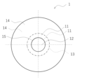
- FIG. 1 is a plan view of an example of a magnetic disk substrate viewed from the direction normal to the main surface.
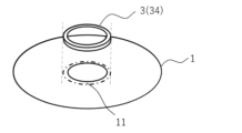
- FIG. 2 is a schematic diagram showing an example of arrangement of a fixing portion of a magnetic disk substrate and a fixing jig.
- FIG. 3 is an exploded perspective view showing an example of a form of incorporating (loading) a magnetic disk into a hard disk drive.
- FIG. 4 is a flowchart for explaining the aluminum alloy substrate for magnetic disk of the present invention and the method for manufacturing a magnetic disk using the same.
- FIG. 5 is a flowchart for explaining the magnetic disk glass substrate of the present invention and the method for manufacturing a magnetic disk using the glass substrate.
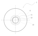
- FIG. 6 is a schematic diagram illustrating positions on the magnetic disk substrate where Rq was measured in the example.
- FIG. 7 is a magnetic disk substrate showing the arrangement relationship of the magnetic disk substrate, the inner peripheral edge sensor, and the outer peripheral edge sensor when measuring the maximum displacement H and the attenuation rate E of the displacement in the example. It is a schematic diagram seen from the side direction of. In FIG. 7(a), the magnetic disk substrate is in a stationary state, and in FIG. 7(b), the magnetic disk substrate is deformed by vibration and bent downward in the plate thickness direction.
- FIG. 8 is a schematic diagram for explaining how to obtain the maximum displacement amount H and the attenuation rate E of the displacement amount obtained in the example.
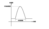
- FIG. 9 is an explanatory diagram showing an example of impact pulses applied in the impact test.
- the magnetic disk substrate 1 is a substrate used for manufacturing the magnetic disk 2, and generally has a disk shape or an annular shape.
- FIG. 1 is a plan view of an example of a magnetic disk substrate viewed from the direction normal to one main surface.
- a magnetic disk substrate 1 shown in FIG. 1 has a disk-like shape and has a circular hole 12 in the center. Although the magnetic disk substrate 1 may be disc-shaped without the circular hole 12, it is preferably disc-shaped with the circular hole 12 in the center.
- the magnetic disk substrate 1 has a pair of front and back main surfaces 14 .
- the magnetic disk substrate 1 has fixing portions 11 on two principal surfaces 14, that is, front and back surfaces.
- the fixing portion 11 is a portion that comes into contact with the fixing jig 3 when the magnetic disk substrate 1 is used as the magnetic disk 2 and incorporated into a hard disk device.
- the fixed part 11 is (concentrically) arranged in a (concentric) circle at a distance of 32 mm or less, preferably 30 mm or less from the center of the magnetic disk substrate 1 from the inner edge arranged at the inner peripheral end portion 15 of the magnetic disk substrate 1. It is a (concentric) annular portion defined by the outer edge (virtual line 13).
- the fixing portion 11 When used for a 2.5-inch hard disk device, the fixing portion 11 is formed at a distance of 29 mm or less, preferably 27 mm or less from the inner edge of the magnetic disk substrate 1 located at the inner peripheral end portion 15 of the magnetic disk substrate 1 and the center of the magnetic disk substrate 1 . It is an annular portion defined by an outer edge (virtual line 13) that is circularly arranged at a distance.
- the inner diameter of the fixing portion 11 matches the inner diameter of the magnetic disk substrate 1 , but the inner diameter of the fixing portion 11 may be slightly larger than the inner diameter of the magnetic disk substrate 1 .
- the outer diameter of the fixing portion 11 can be set according to the outer diameter of the fixing jig 3 used when fixing the magnetic disk 2, and may be the same as the outer diameter of the fixing jig 3, slightly larger, or slightly smaller. can do.
- a magnetic layer is formed outside in the direction (radial direction) from the center of the fixed portion 11 toward the outer circumference.
- no magnetic layer is formed on the fixed portion 11 of the magnetic disk substrate 1 . In this sense, when the magnetic disk substrate 1 is used as the magnetic disk 2, the fixed portion 11 of the magnetic disk substrate 1 and the fixed portion 21 of the magnetic disk 2 can be regarded as the same.
- the fixing jig 3 is used when the magnetic disk substrate 1 as the magnetic disk 2 is incorporated into the hard disk device.
- the fixing jig 3 usually has a disk-like or annular shape in plan view.
- the fixing jig 3 may be any member that is normally used when the magnetic disk 2 is incorporated into a hard disk drive, and includes a disk clamper 31, a large diameter portion 33a provided in the bearing (also referred to as a large diameter portion of the bearing), spacer 34 and the like.
- the fixing jig 3 can be made of an aluminum alloy.
- FIG. 2 shows an example of arrangement of the fixing jig 3 with respect to the fixing portion 11 on one main surface.
- the fixing part 11 and the fixing jig 3 (34) have the same shape in plan view, and although they are separated in FIG. be done.
- the form of arrangement of the fixing part 11 and the fixing jig 3 when incorporated into the hard disk drive is not particularly limited as long as the position where the fixing jig 3 is arranged is inside the fixing part 11 in a plan view.
- the fixing jig 3 may be in contact with the entire fixing portion 11 in a plan view, or may be in contact with a part of the fixing portion 11 in a plan view.
- FIG. 3 shows an exploded perspective view schematically showing an example of the form of incorporating the magnetic disk 2 into a hard disk drive. Specifically, FIG. 3 shows an example of the arrangement of the magnetic disks 2 when three magnetic disks 2 are incorporated. 3, three magnetic disks 2 are arranged in the order shown in FIG.
- the three magnetic disks 2 are supported by the large-diameter portion 33a of the bearing 33, and are attached to the bearing 33 via two spacers 34.
- the core 33b of the bearing is inserted into the circular hole of the magnetic disk 2 and the circular hole of the spacer .
- the outer diameter of the fixing portion 21 on the magnetic disk 2, the diameter of the large diameter portion 33a of the bearing, the outer diameter of the spacer 34, and the diameter of the disk clamper 31 are the same.
- the inner diameter of the magnetic disk 2 and the inner diameter of the spacer 34 are the same.
- the diameter of the core 33b of the bearing is such that when the magnetic disk 2 and the spacer 34 are inserted, no gap is formed between them.
- the three magnetic disks 2 are assembled in such a manner that the large-diameter portion 33 a of the bearing, the two spacers 34 , the disk clamper 31 , and the fixing portion 21 are in contact with each other.
- 3 does not show the magnetic layer of the magnetic disk 2, external members such as a magnetic head and a lamp, a housing, and the like, from the viewpoint of simply showing the built-in form.
- the form of incorporation is not limited to the form described above, and may be a normal form of incorporation including the above.
- a spacer 34 may be further arranged between the large diameter portion 33 a of the bearing and the magnetic disk 2 .
- the two fixing portions 11, 11 of the two main surfaces 14, 14 each have a surface roughness root-mean-square deviation Rq of 0.01 to 0.44 ⁇ m.
- the surface roughness root-mean-square deviation Rq is within the above range, when the magnetic disk substrate 1 is used as the magnetic disk 2 and incorporated into a hard disk drive, vibration of the magnetic disk 2 can be suppressed and impact resistance can be improved. .
- the fulcrum distribution of the deformation also referred to as the difference in the amount of displacement
- the root mean square deviation Rq of the surface roughness of the fixing portion 11 is preferably 0.10 to 0.44 ⁇ m, more preferably 0.15 to 0.40 ⁇ m.
- the root-mean-square deviation Rq of the surface roughness of the fixing portion 11 can also be 0.17 to 0.40 ⁇ m.
- the root-mean-square deviation Rq of the surface roughness of the fixing portion 11 can be measured according to JIS B 0601-2001 by the method described in Examples. Even when the magnetic disk substrate 1 is used as the magnetic disk 2, by measuring the root mean square roughness Rq of the surface roughness at the fixed portion 21 of the magnetic disk 2, the fixed portion 11 of the magnetic disk substrate 1 can be measured.
- a root-mean-square roughness Rq of the surface roughness can be measured. This is because the fixed portion 21 of the magnetic disk 2 and the fixed portion 11 of the magnetic disk substrate 1 are usually the same.
- the method for adjusting the root-mean-square deviation Rq of the surface roughness is not particularly limited. Dilute the polishing liquid with water of 1 M ⁇ cm or more, keep stirring while supplying the polishing liquid, and when supplying the polishing liquid to the polishing pad via a pipe, the pipe should have an electrical resistivity of 10 M ⁇ cm. The above range can be set by cleaning the pipe so that the electrical resistivity of the water becomes 1 M ⁇ cm or more at the pipe outlet when the above water is supplied from the pipe inlet. Regardless of which preparation method is employed, Rq tends to be small. From the viewpoint of lowering the electrical resistivity, the water used for diluting the polishing liquid is preferably pure water, and more preferably ion-exchanged water or distilled water.
- the absolute value of the difference ⁇ Rq between the Rqs of the two fixing portions 11 of the magnetic disk substrate 1 (that is, the absolute value of Rq of the fixing portion 11 on the front side ⁇ Rq of the fixing portion 11 on the back side) is 0.01 to 0. It is preferably 0.11 ⁇ m.
- the vibration damping rate of the magnetic disk substrate 1 can be increased. It is believed that by aligning the surface roughness of the front and back surfaces of the fixing portion 11, the difference in the amount of displacement between the top and bottom of the substrate is reduced, and the vibration is damped more quickly.
- the absolute value of ⁇ Rq is preferably 0.01 to 0.08 ⁇ m, more preferably 0.01 to 0.05 ⁇ m, and more preferably 0.01 to 0.05 ⁇ m. It is even more preferable to have
- the method for adjusting the absolute value of ⁇ Rq is not particularly limited. The above range can be set by, for example, reversing the thickness direction up and down once or more.
- the thickness of the magnetic disk substrate 1 can be the same as that of a normal magnetic disk substrate, and can be further reduced.
- the plate thickness of the magnetic disk substrate 1 is preferably 0.50 mm or less. Although the lower limit of the plate thickness of the magnetic disk substrate 1 is not particularly limited, it is practically 0.30 mm or more.
- the outer diameter of the magnetic disk substrate 1 can be the same as the outer diameter of a normal magnetic disk substrate. When the magnetic disk substrate 1 is used for a 2.5-inch hard disk device, the outer diameter of the magnetic disk substrate 1 is preferably 65 mm or more. The upper limit is limited by the internal dimensions of the housing of the hard disk device, and 70 mm or less is practical.
- the outer diameter of the magnetic disk substrate 1 of the present invention is preferably 95 mm or more, more preferably 97 mm or more.
- the upper limit is limited by the inner dimensions of the case, and 101 mm or less is practical.
- the inner diameter of the magnetic disk substrate 1 can be the same as that of a normal magnetic disk substrate.
- the inner diameter of the magnetic disk substrate 1 of the present invention is preferably 22 mm or less.
- the lower limit is restricted by the diameter of the rotating shaft, and 18 mm or more is practical.
- the inner diameter of the magnetic disk substrate 1 of the present invention is preferably 26 mm or less.
- a preferable form of the magnetic disk substrate 1 is a form having an outer diameter of 97 mm or more, an inner diameter of 26 mm or less, and a plate thickness of 0.5 mm or less.
- the magnetic disk substrate 1 of the present invention has the following configuration and exhibits particularly favorable effects when used in a hard disk drive having the following specifications.
- the magnetic disk substrate 1 satisfies the root mean square deviation Rq, the maximum value H and its attenuation factor E can be suppressed within the following ranges. As a result, when the substrate 1 is incorporated into a hard disk device as the magnetic disk 2, even if vibration occurs, the generation of particles, scratches, and defects on the surface of the magnetic disk can be effectively suppressed.
- One magnetic disk substrate 1 is sandwiched from above and below by the fixing jigs 3 (disk clamper 31 and spacer 34) at the fixing portion 11 and fixed horizontally to the bearing 33. Then, 2.
- An impact of 8 msec and 490 m/s 2 is applied from below (from the bearing 33 side toward the disk clamper 31 side) in the normal direction (board thickness direction) of the main surface 14 of the magnetic disk substrate 1 .
- the vertical direction means the plate thickness direction (sandwiching direction) of the magnetic disk substrate.
- the maximum value H of the displacement is obtained by vibrating the magnetic disk substrate 1 due to the impact in this impact test, and plotting the displacement in the plate thickness direction of the outer peripheral edge due to this impact against time as shown in FIG. It is the absolute value ( ⁇ m) of the first large downward displacement in the displacement-time graph.
- the attenuation rate E of the amount of displacement refers to the slope ( ⁇ m/msec) when connecting the vertices of the displacements that greatly decrease in the first and second times in this graph.
- the impact test can be performed by the method described in Examples. This impact test is performed using the magnetic disk substrate 1 on which no magnetic layer is formed. does not substantially affect E.
- the maximum value H of displacement in the plate thickness direction of the outer peripheral edge of the magnetic disk substrate 1 is preferably 165 ⁇ m or less.
- the maximum displacement amount H is more preferably 164 ⁇ m or less, more preferably 150 ⁇ m or less, and even more preferably 130 ⁇ m or less.
- the lower limit of the maximum displacement H is not particularly limited, it is practically 100 ⁇ m or more.
- the attenuation rate E of the displacement amount in the plate thickness direction of the outer peripheral end portion of the magnetic disk substrate 1 is 17.7 ⁇ m/msec or more.
- the upper limit of the attenuation rate E is not particularly limited, it is practically 30 ⁇ m/msec or less. More preferably, the magnetic disk substrate 1 has a maximum value H of displacement of 165 ⁇ m or less and an attenuation rate E of displacement of 17.7 ⁇ m/msec or more.
- the displacement H and attenuation factor E measured in the same manner except that the magnetic disk 2 is used are the displacement of the magnetic disk substrate 1.
- H and the decay factor E can be considered. This is because the magnetic layer does not affect these measured values as described above.
- the conditions of the above impact test are the impacts when fixing the hard disk drive to the HDD mount rack, computer, etc. during actual use (inserting the hard disk drive terminal into the terminal of the blade, etc., and inserting the blade into the side guide of the blade server). It is a condition that reproduces the shock when it reaches the deepest end by pushing it in while sliding it.
- the action time was set to 2.8 msec
- the maximum acceleration (applied acceleration) was set to 490 m/s 2 .
- FIG. 9 shows an explanatory diagram of impact pulses used in the impact test.
- the vertical axis is acceleration and the horizontal axis is time.
- a shock pulse is composed of an applied acceleration G (corresponding to the maximum acceleration) and an action time.
- the magnetic disk 2 of the present invention is a magnetic disk using the magnetic disk substrate 1 described above.
- the magnetic disk substrate 1 of the present invention can be used as the magnetic disk 2 by forming a magnetic layer on at least one of its main surfaces 14 . It is preferable to form a magnetic layer on both main surfaces 14 .
- the structure of the magnetic disk 2 can be the same as that of a normal magnetic disk, except that it has the fixing portion 21 described above.
- the fixing part 21 can apply the description of the fixing part 11, and can have the same root mean square deviation of surface roughness Rq, inner diameter, and outer diameter as those of the fixing part 11. It is the same.
- the magnetic layer can have the same structure as a normal magnetic disk. Although the thickness of the magnetic layer is not particularly limited, it is preferably 1 to 100 nm.
- the magnetic disk 2 Since the magnetic disk 2 obtained using the magnetic disk substrate 1 of the present invention has the above characteristics, the magnetic disk 2 is a 3.5-inch normal hard disk and is required to have more severe impact resistance. It can also be used with .5 inch or 3.5 inch hard disks. Thicknesses of 7 mm, 9.5 mm, and 12.5 mm are known as thicknesses of major 2.5-inch hard disk enclosures, and thicknesses of 20 mm, 26 mm, etc. are known as thicknesses of major 3.5-inch hard disk enclosures. If the thickness of the magnetic disk 2 is 0.5 mm, the number of magnetic disks 2 that can be mounted in a 26 mm-thick housing for a normal 3.5-inch hard disk is 9 or less.
- the thickness of the magnetic disk 2 is set to less than 0.5 mm, it is possible to mount 10 or more magnetic disks in the hard disk without increasing the thickness of the housing significantly exceeding 26 mm.
- the gap between the main surface of the magnetic disk and an external member such as a ramp on the same side as the main surface is sometimes set to about 200 ⁇ m.
- the gap between the magnetic disk 2 and the external member can be further reduced. In this way, it is possible to mount many magnetic disks in the hard disk device. According to the invention, the gap can be as narrow as 170 ⁇ m, or even 165 ⁇ m.
- Materials with excellent mechanical properties and workability are generally used as materials for the magnetic disk substrate 1.
- aluminum alloys and glass can be preferably used.
- conventional aluminum alloys and glass used as substrate materials can be used without particular limitations.
- a magnetic disk substrate manufactured using an aluminum alloy is sometimes referred to as an aluminum alloy substrate
- a magnetic disk substrate manufactured using glass is sometimes referred to as a glass substrate.
- Al-Mg alloys, Al-Fe-Mn-Ni alloys, and Al-Fe-Mn-Mg-Ni alloys can be preferably used as aluminum alloys for the substrate material, but are not limited to these. do not have.
- Al-Mg alloy for example, JIS5086 (A5086) (Mg: 3.5 to 4.5% by mass, Fe: 0.50% by mass or less, Si: 0.40% by mass or less, Mn: 0.20 ⁇ 0.70% by mass, Cr: 0.05 to 0.25% by mass, Cu: 0.10% by mass or less, Ti: 0.15% by mass or less, and Zn: 0.25% by mass or less, and the balance Al and unavoidable impurities) can be used.
- JIS5086 A5086
- Fe 0.50% by mass or less
- Si 0.40% by mass or less
- Mn 0.20 ⁇ 0.70% by mass
- Cr 0.05 to 0.25% by mass
- Cu 0.10% by mass or less
- Ti 0.15% by mass or less
- Zn 0.25% by mass or less
- the method for manufacturing the magnetic disk aluminum alloy substrate is not particularly limited as long as it is a method capable of manufacturing a magnetic disk substrate having the surface roughness root-mean-square deviation Rq within the above range. From the viewpoint of making the surface roughness root-mean-square deviation Rq within the above range, the method for manufacturing an aluminum alloy substrate for a magnetic disk has a grain size of 0.03 ⁇ m or more and 1.0 ⁇ m or less (a grain size of 0.1 ⁇ m or more and 1.0 ⁇ m or less).
- the rough polishing step and/or the fine polishing step is preferably a step of polishing while supplying a polishing liquid to the polishing pad from the upper surface plate side.
- the rough polishing step and/or the fine polishing step is preferably a step of polishing while supplying a polishing liquid of 10 ml/min or more per disk blank, which will be described later.
- the rough polishing step and/or the fine polishing step are preferably steps using a polishing liquid diluted with water having an electrical resistivity of 1 M ⁇ cm or more.
- the polishing liquid under stirring to the polishing pad.
- the fine polishing step it is preferable to turn the disk blank upside down in the plate thickness direction once or more during the polishing step.
- the outlet of the pipe Prior to the rough polishing step and/or the fine polishing step, when water having an electric resistivity of 10 M ⁇ cm or more is supplied from the inlet of the pipe to which the polishing liquid is supplied, the outlet of the pipe has an electrical resistivity of 1 M ⁇ cm or more. It is preferable to clean to an extent.
- FIG. 4 is a flowchart illustrating an example of a method of manufacturing an aluminum alloy substrate and a magnetic disk using the same.
- the steps of preparing an aluminum alloy (step S101) to cold rolling (step S105) are steps of manufacturing an aluminum alloy material by melting and casting and making it into an aluminum alloy plate.
- an aluminum alloy disc blank is manufactured by a pressure flattening process (step S106).
- the manufactured disc blank is subjected to pretreatment such as cutting/grinding process (step S107), degreasing/etching process (step S108), zincate process (step S109), Ni--P plating process (step S110).
- step S111 a rough polishing step
- step S112 a fine polishing step
- a molten metal of an aluminum alloy material having the above composition is prepared by heating and melting according to a conventional method (step S101).
- the prepared molten metal of the aluminum alloy material is cast by a semi-continuous casting (DC casting) method, a continuous casting (CC casting) method, or the like to cast the aluminum alloy material (step S102).
- DC casting may be vertical semi-continuous casting or horizontal semi-continuous casting.
- the manufacturing conditions of the aluminum alloy material in the DC casting method and the CC casting method are as follows.
- the molten metal poured through the spout is cooled by cooling water discharged directly to the bottom block, the water-cooled walls of the mold, and the outer periphery of the ingot (ingot). Then, it is drawn downward as an aluminum alloy ingot.
- the ingot obtained by this process is sometimes called a slab.
- a molten metal is supplied through a casting nozzle between a pair of rolls (or a belt caster or a block caster), and heat is removed from the rolls to directly cast an aluminum alloy thin plate.
- a major difference between the DC casting method and the CC casting method is the cooling rate during casting.
- CC casting which has a high cooling rate, is characterized by a smaller size of second phase particles than DC casting.
- step S104 the aluminum ingot obtained by DC casting is hot-rolled into a plate material.
- step S103 the DC cast aluminum alloy ingot can be subjected to a homogenization treatment as necessary (step S103).
- step S105 is performed following step S102 without performing these steps.
- heat treatment is preferably performed at 280 to 620° C. for 0.5 to 30 hours, and more preferably at 300 to 620° C. for 1 to 24 hours. . If the heating temperature during the homogenization treatment is less than 280° C. or the heating time is less than 0.5 hours, the homogenization treatment may be insufficient and the loss factor may vary greatly among aluminum alloy substrates. If the heating temperature during the homogenization treatment exceeds 620°C, there is a risk that the aluminum alloy ingot will melt. Even if the heating time in the homogenization process exceeds 30 hours, the effect is saturated, and no further remarkable improvement effect can be obtained.
- step S104 the aluminum alloy ingot (DC casting) that has been homogenized or not is hot-rolled into a plate material (step S104).
- the conditions for hot rolling are not particularly limited, but the hot rolling start temperature is preferably 250 to 600°C, and the hot rolling end temperature is preferably 230 to 450°C.
- the hot-rolled rolled plate or the cast plate cast by the CC casting method is cold-rolled into an aluminum alloy plate of about 0.3 to 0.6 mm (step S105).
- the cold rolling conditions are not particularly limited, and may be determined according to the required product plate strength and plate thickness, and the rolling reduction is preferably 10 to 95%.
- Annealing treatment may be performed before cold rolling or during cold rolling to ensure cold rolling workability.
- batch heating is preferably performed at 300 to 450° C. for 0.1 to 10 hours, and continuous heating is performed at 400 to 500° C. for 0 to 10 hours. It is preferable to carry out under the condition of holding for 60 seconds.
- the holding time of 0 seconds means cooling immediately after reaching the desired holding temperature.
- the aluminum alloy plate obtained by cold rolling is punched into a disk shape to obtain a disk-shaped aluminum alloy plate.
- the disk-shaped aluminum alloy plate becomes a disk blank by a pressure flattening process (step S106).
- the pressure flattening treatment the disk-shaped aluminum alloy plate is subjected to pressure annealing at 200 to 450 ° C. for 0.5 to 10 hours, for example, while applying a load of 30 to 100 MPa in the atmosphere. is performed to produce a flattened disc blank.
- the disk blank is subjected to cutting/grinding (step S107) and, if necessary, heat treatment before the zincate treatment or the like.
- the inner and outer peripheries of the disk blank are cut to adjust the shape, and the main surface is ground.
- the recording surface of the disc blank may be cut as a preliminary treatment for grinding.
- the inner and outer peripheral end faces may be chamfered. Grinding can be performed using a SiC grindstone of No. 800 to 4000 and a commercially available batch-type double-side simultaneous grinder.
- This double-sided simultaneous polishing machine consists of a cast iron upper surface plate and a lower surface plate, a carrier that holds a plurality of aluminum substrates between the upper surface plate and the lower surface plate, and contact between the upper surface plate and the lower surface plate. and a SiC grindstone attached to the surface. Grinding is performed by rotating the upper and lower surface plates in opposite directions while holding the disk blank with a carrier. The rotation speed of the upper and lower surface plates can be 10 to 30 rpm. Since the carrier rotates with the sun gear, the disk blank is ground while planetary motion is performed on the grindstone. Further, when the heat treatment is performed, the heat treatment is performed under the condition that the disk blank is held at 200 to 350° C. for 5 to 60 minutes. Distortion caused by cutting and grinding can be removed by heat treatment.
- the disk blank surface is degreased and etched (step S108).
- the degreasing treatment can be carried out by a conventional method, and for example, it is preferable to use a commercially available degreasing solution under conditions of a temperature of 40 to 70° C., a treatment time of 3 to 10 minutes, and a concentration of 10 to 500 ml/L.
- the etching treatment can be performed by a conventional method, for example, using a commercially available etchant, etc., at a temperature of 50 to 75° C., a treatment time of 0.5 to 5 minutes, and a concentration of 1 to 50 mL/L. preferable.
- zincate processing (Zn replacement processing) is performed on the disc blank surface (step S109).
- a zincate film is formed on the disk blank surface.
- a commercially available zincate treatment solution can be used for the zincate treatment, and is preferably carried out under conditions of a temperature of 10 to 35° C., a treatment time of 0.1 to 5 minutes, and a concentration of 100 to 500 mL/L.
- the zincate treatment is performed at least once, and may be performed twice or more. By performing the zincate treatment multiple times, fine Zn can be precipitated to form a uniform zincate film. When the zincate treatment is performed twice or more, the Zn stripping treatment can be performed in between.
- the Zn stripping treatment is preferably performed using an HNO 3 solution under conditions of a temperature of 15 to 40° C., a treatment time of 10 to 120 seconds, and a nitric acid concentration of 10 to 60%.
- the second and subsequent zincate treatments are preferably carried out under the same conditions as the first zincate treatment.
- the zincate-treated disk blank surface is subjected to electroless Ni--P plating (step S110) as a base treatment for adhering the magnetic material.
- electroless Ni—P plating it is preferable to use a commercially available plating solution or the like and perform plating under conditions of a temperature of 80 to 95° C., a treatment time of 30 to 180 minutes, and a Ni concentration of 3 to 10 g/L. Pure water cleaning may be performed between each treatment from the degreasing treatment to the zincate treatment.
- the plated surface is subjected to a rough polishing step and a fine polishing step as polishing processes for smoothing (steps S111 and S112).
- the details are not particularly limited as long as the root-mean-square deviation Rq of the surface roughness can be obtained.
- a polishing liquid containing large-diameter abrasive grains with a particle size of 0.03 ⁇ m or more and 1.0 ⁇ m or less and an average particle size of 0.2 ⁇ m or more and 0.85 ⁇ m or less and a hard or soft polishing pad the main Roughly polish the surface.
- the main surface is subjected to precision polishing. polishing.
- small-diameter abrasive grains used in the precision polishing step those having a smaller diameter than the large-diameter abrasive grains used in the rough polishing step are used.
- hard means hardness (Asker C) of 85 or more measured by the measuring method specified in the standard of the Japan Rubber Association (compliant standard: SRIS0101), and "soft” means hardness of 60 to 80.
- the average particle diameter (d50) is the so-called median diameter, and the particle size distribution is measured by a laser diffraction/scattering method, and the particle size when the cumulative distribution is 50% when the total volume of the particles is 100%.
- polishing conditions in the rough polishing step are influenced by the aluminum alloy used, the processing conditions in steps S101 to S110, etc., and thus are difficult to uniquely determine. 5 to 35 rpm, polishing solution supply rate of 10 to 500 ml/min (more preferably 50 to 500 ml/min), polishing time of 1 to 10 min, processing pressure of 10 to 100 g/cm 2 , polishing amount of 0.1 to 10 ⁇ m. can be It is preferable to turn the disk blank upside down in the plate thickness direction during the rough polishing step. The inversion may be performed once or multiple times.
- the timing of turning over the disk blank is not particularly limited, but it is preferable that both surfaces of the disk blank are polished evenly, and it is more preferable to turn over when half of the total polishing time of the rough polishing process has elapsed.
- Other polishing conditions in the precision polishing step are influenced by the aluminum alloy used, the processing conditions from step S101 to rough polishing, etc., and are difficult to determine unambiguously. 5 to 35 rpm, polishing liquid supply rate of 10 to 500 ml/min (more preferably 50 to 500 mL/min), polishing time of 1 to 10 min, processing pressure of 10 to 100 g/cm 2 , polishing amount of 0.01 to 1 ⁇ m.
- the disk blank upside down in the plate thickness direction during the precision polishing step can be It is preferable to turn the disk blank upside down in the plate thickness direction during the precision polishing step.
- the inversion may be performed once or multiple times.
- the timing of turning over the disk blank is not particularly limited, but it is preferable that both surfaces of the disk blank are polished evenly, and it is more preferable to turn over when half of the total polishing time in the precision polishing process has elapsed.
- the rough polishing step and the rough polishing step can be carried out using a commercially available batch-type double-side simultaneous polishing machine.
- This double-sided simultaneous polishing machine includes an upper surface plate and a lower surface plate made of cast iron, a carrier that holds a plurality of disk blanks between the upper surface plate and the lower surface plate, and contact between the disk blanks on the upper surface plate and the lower surface plate. Attached to the surface are polishing pads (ie, the number of polishing pads is twice the number of disk blanks).
- a plurality of disk blanks are held between an upper surface plate and a lower surface plate by a carrier, and each disk blank is pressed under a predetermined working pressure by the upper surface plate and the lower surface plate.
- each disk blank is collectively pressed by the polishing pads from above and below (parallel to the direction of gravity).
- the upper surface plate and the lower surface plate are rotated in different directions.
- the carrier since the carrier also rotates by the sun gear, the disk blank performs planetary motion. This causes the disc blank to slide over the surface of the polishing pad, polishing both surfaces simultaneously.
- the polishing pad is porous (having bag-like pores with an open surface), the polishing liquid is supplied between the polishing pad and the disc blank through the polishing pad. Supply of the polishing liquid to the polishing pad can be carried out by a normal method.
- the polishing liquid can be supplied to the polishing pad through a pipe from a tank that stores the polishing liquid. It is preferable that the tank storing the polishing liquid has a stirring means.
- the polishing liquid is preferably supplied to the polishing pad from the upper surface plate side. Supplying the grinding liquid from the upper surface plate side to the polishing pad specifically means making holes in the upper surface plate and the polishing pad, and dropping and pouring the grinding liquid into the holes from above.
- a porous polishing pad is used as the polishing pad used in the rough polishing process and the precision polishing process.
- the aluminum alloy substrate for a magnetic disk according to the present invention is manufactured by the polishing process (surface polishing) after the electroless Ni--P plating process described above.
- the step of attaching the magnetic material can be performed by a normal method.
- the magnetic layer is formed by attaching a magnetic material to the surface of the aluminum alloy substrate.
- Glass substrate A glass substrate will be described.
- Glass ceramics such as amorphous glass and crystallized glass can be used as the material of the glass plate.
- amorphous glass from the viewpoint of moldability, workability, and product surface roughness.
- aluminosilicate glass, soda lime glass, soda aluminosilicate glass, aluminoborosilicate glass, borosilicate glass, etc. is preferred.
- a preferred form of the glass used for the magnetic disk substrate is SiO 2 : 55 to 75% as a main component, Al 2 O 3 : 0.7 to 25%, Li 2 O: 0.01 to 6%, Na 2 . O: 0.7-12%, K 2 O: 0-8%, MgO: 0-7%, CaO: 0-10%, ZrO 2 : 0-10%, TiO 2 : 0-1% were added. is glass.
- the method for manufacturing the magnetic-disk glass substrate is not particularly limited as long as it is a method capable of manufacturing a magnetic-disk substrate having the surface roughness root-mean-square deviation Rq within the above range. From the viewpoint of setting the surface roughness root-mean-square deviation Rq within the above range, the method for manufacturing a magnetic disk glass substrate has a grain size of 0.1 ⁇ m or more and 1.0 ⁇ m or less and an average grain size of 0.2 ⁇ m or more and 0.2 ⁇ m or more.
- a step of roughly polishing the main surface using a polishing liquid containing abrasive grains of 85 ⁇ m or less and a hard polishing pad It is preferable to include at least a step of precision polishing the main surface using a polishing liquid containing abrasive grains of 02 ⁇ m or more and 0.08 ⁇ m or less and a soft polishing pad.
- the conditions in the rough polishing step and the fine polishing step can also be applied to the conditions in the production of the aluminum alloy substrate.
- abrasive grains with a grain size of 0.03 ⁇ m or more and 1.0 ⁇ m or less can be used.
- the rough polishing step corresponds to step S204 described later, and the fine polishing step corresponds to step S205 described later.
- the description of steps S204 and S205 can be referred to.
- At least one of the following preferred steps is preferably performed in the rough polishing step and/or the fine polishing step.
- the rough polishing step and/or the fine polishing step is preferably a step of polishing while supplying a polishing liquid to the polishing pad from the upper surface plate side.
- the rough polishing step and/or the fine polishing step is preferably a step of polishing while supplying a polishing liquid of 10 ml/min or more per disk blank, which will be described later.
- the rough polishing step and/or the fine polishing step are preferably steps using a polishing liquid diluted with water having an electrical resistivity of 1 M ⁇ cm or more.
- a polishing liquid diluted with water having an electrical resistivity of 1 M ⁇ cm or more it is preferable to supply the polishing liquid under stirring to the polishing pad.
- water having an electric resistivity of 10 M ⁇ cm or more is supplied from the inlet of the pipe to which the polishing liquid is supplied, the outlet of the pipe has an electrical resistivity of 1 M ⁇ cm or more. It is preferable to clean to an extent.
- FIG. 5 is a flowchart for explaining an example of a method of manufacturing a glass substrate and a magnetic disk using the same.
- a glass plate having a predetermined thickness is prepared (step S201).
- the prepared glass plate is subjected to coring, and the inner and outer peripheral edges are polished to form a disc-shaped disc blank (step S202).
- a step of lapping the disk-shaped disk blank is performed (step S203).
- the molded or lapped disk blanks are collectively sandwiched between upper and lower polishing pads, and a rough polishing step (step S204) is performed in which a plurality of disk blanks are simultaneously polished with cerium oxide abrasive grains.
- step S204 Each disc blank polished in step S204 is further subjected to a precision polishing step (step S205) for polishing with colloidal silica abrasive grains at the same time to manufacture a glass substrate.
- the manufactured glass substrate becomes a magnetic disk through the step of attaching a magnetic substance (step S206).
- the preparation of the glass plate in step S201 can be carried out using a known manufacturing method such as a float method, a down-draw method, or a direct press method using molten glass as a raw material. Further, by using a redraw method in which a base glass plate manufactured by a float method or the like is heated to soften and stretched to a desired thickness, a glass plate having a small variation in thickness can be manufactured relatively easily. preferable.
- a disk-shaped disk blank is formed from the glass plate prepared in step S201 through a coring process and a process of polishing the inner and outer peripheral edges.
- the formed disk blank is a disk-shaped disk blank having two main surfaces and a circular hole formed in the center.
- the thickness of the disk blank can be adjusted by carrying out the lapping process of step S203 and lapping the disk-shaped disk blank formed in step S202.
- This lapping step is preferably performed when the thickness of the glass plate varies greatly, such as when the redraw method is not adopted in step S201.
- the lapping process can be performed so that the variation in the thickness of the glass plate is about ⁇ 3 ⁇ m.
- the lapping process can be performed by a conventional method, for example, using a batch-type double-sided polishing machine using diamond pellets.
- polishing step S202 or S203 the main surface of the disc blank obtained in step S202 or S203 is subjected to polishing.
- this polishing step it is preferable to perform polishing in a plurality of stages with the diameter of the abrasive grains being adjusted.
- This polishing process includes polishing in at least two stages, rough polishing (S204) and precision polishing (S205).
- the main surface of the disk blank is roughly polished.
- Rough polishing is carried out using a hard polishing pad and a polishing liquid containing abrasive grains with a particle size of 0.1 ⁇ m or more and 1.0 ⁇ m or less and an average particle size of 0.2 ⁇ m or more and 0.85 ⁇ m or less. can be done.
- Other polishing conditions for rough polishing are as follows: use a hard polishing pad with a hardness of 86 to 88, a polishing surface plate rotation speed of 5 to 35 rpm, a sun gear rotation speed of 5 to 35 rpm, and a polishing liquid supply rate of 10 to 500 ml/ml.
- the polishing liquid preferably contains abrasive grains made of cerium oxide having a particle size of 0.1 ⁇ m or more and 1.0 ⁇ m or less and an average particle size of 0.2 ⁇ m or more and 0.85 ⁇ m or less. It is preferable to turn the disk blank upside down in the plate thickness direction during the rough polishing step. The inversion may be performed once or multiple times.
- the timing of turning over the disk blank is not particularly limited, but it is preferable that both surfaces of the disk blank are polished evenly, and it is more preferable to turn over when half of the total polishing time of the rough polishing process has elapsed.
- the rough polishing step and the rough polishing step can be carried out using a commercially available batch-type double-side simultaneous polishing machine. Also in the method for manufacturing a glass substrate, the simultaneous double-sided polishing machine described in the method for manufacturing an aluminum substrate can be used.
- the rough-polished main surface is precision-polished.
- the polishing pad of the double-side simultaneous polishing machine is replaced with a softer polishing pad for precision polishing made of, for example, urethane foam, and the grain size is 0.01 ⁇ m or more and less than 0.1 ⁇ m, and the average grain size is 0.02 ⁇ m.
- the polishing can be carried out by polishing the glass substrate using the polishing pad while supplying a polishing liquid containing polishing abrasive grains made of colloidal silica as small as 0.08 ⁇ m or less. As a result, the main surface of the disrank is mirror-polished, and a magnetic-disk glass substrate is manufactured.
- polishing conditions for precision polishing are as follows: use a soft polishing pad with a hardness of 75 to 77; rotate the polishing surface plate at 5 to 35 rpm; minutes (more preferably 50 to 500 mL/min), a processing pressure of 10 to 120 g/cm 2 , a polishing time of 1 to 10 minutes, and a polishing amount of 5 to 15 ⁇ m per side. Also, the polishing amount can be 0.01 to 1 ⁇ m. It is preferable to turn the disk blank upside down in the plate thickness direction during the precision polishing step. The inversion may be performed once or multiple times. The timing of turning over the disk blank is not particularly limited, but it is preferable that both surfaces of the disk blank are polished evenly, and it is more preferable to turn over when half of the total polishing time in the precision polishing process has elapsed.
- chemical strengthening treatment with a sodium nitrate solution or a potassium nitrate solution can be performed during the polishing process.
- the step of attaching the magnetic material can be performed by a normal method.
- Examples 1-3 and Comparative Examples 1-2 magnetic disk substrates having an outer diameter of 97 mm, an inner diameter of 25 mm, and a thickness of 0.50 mm were produced. Details of each example are described below.
- Example 1 A5086 alloy (aluminum alloy A) was melted according to a standard method, and a slab was obtained by DC casting (vertical semi-continuous casting) to a width of 1310 mm and a plate thickness of 500 mm. Each of the four sides of this slab was chamfered by 10 mm, homogenized at 540° C. for 6 hours, and hot rolled at a hot rolling start temperature of 540° C. and a hot rolling end temperature of 340° C. to obtain a plate thickness of 3.5 mm. A 0 mm hot-rolled sheet was obtained. This hot-rolled sheet was cold-rolled to obtain a cold-rolled sheet having a thickness of 0.48 mm.
- This cold-rolled sheet is punched into an annular ring with an inner diameter of 24 mm and an outer diameter of 98 mm, and is subjected to heat treatment at 320° C. for 3 hours while applying pressure of 30 MPa using a continuous annealing furnace in the atmosphere. Pressure annealing was performed and pressure flattening treatment was performed. A disc blank was thus obtained. Further, by cutting the inner and outer circumferences of the disc blank, an annular disc blank having an inner diameter of 25 mm and an outer diameter of 97 mm was obtained. At this time, the inner and outer peripheral end surfaces were chamfered at the same time. The disk blank after this processing was surface-ground with a No. 4000 SiC grindstone to a thickness of 0.46 mm.
- Both surfaces of this disk blank were subjected to degreasing treatment, etching treatment, first zincate treatment, Zn stripping treatment, and second zincate treatment as follows.
- the degreasing treatment was carried out using a degreasing solution AD-68F (trade name, manufactured by Uyemura & Co., Ltd.) under conditions of a temperature of 45° C., a treatment time of 3 minutes, and a concentration of 500 mL/L.
- Etching was performed using AD-107F (trade name, manufactured by Uemura & Co., Ltd.) etchant under conditions of a temperature of 60° C., a processing time of 2 minutes, and a concentration of 50 mL/L.
- the first zincate treatment was performed using a zincate treatment liquid AD-301F-3X (trade name, manufactured by Uemura & Co., Ltd.) under conditions of a temperature of 20°C, a treatment time of 1 minute, and a concentration of 200 mL/L.
- the Zn stripping treatment was performed using a commercially available nitric acid reagent under conditions of a temperature of 25° C., a treatment time of 60 seconds, and a nitric acid concentration of 30%.
- the second zincate treatment was performed under the same conditions as the first zincate treatment. In addition, cleaning with pure water was performed between each treatment from the degreasing treatment to the second zincate treatment.
- Nimden HDX (trade name, manufactured by Uemura & Co., Ltd.) plating solution under the conditions of a temperature of 88°C, a treatment time of 130 minutes, and a Ni concentration of 6 g/L.
- the Ni--P plated disk blank was set in a double-sided simultaneous polishing machine (trade name: 9B double-sided polishing machine manufactured by SPEEDFAM), and a rough polishing step and a fine polishing step were performed to produce an aluminum alloy substrate. Details will be described below.
- the polishing conditions in the rough polishing step are as follows: a urethane foam polishing pad having a hardness of 66; aluminum oxide having a particle size of 0.03 ⁇ m or more and 1.0 ⁇ m or less and an average particle size of 0.85 ⁇ m; was used.
- Other polishing conditions in the rough polishing process were as follows: polishing liquid was supplied from the upper surface plate side, the number of revolutions of the polishing surface plate was 35 rpm, the polishing liquid supply rate was 100 ml/min, the polishing time was 2 minutes, and the processing pressure was 100 ml/min. was 80 g/cm 2 and the polishing amount was 1 ⁇ m. Further, the disc blank was placed upside down in the plate thickness direction and polished under the same conditions.
- a precision polishing step was performed.
- pure water is added to a urethane foam polishing pad having a hardness of 76 and colloidal silica having a particle size of 0.01 ⁇ m or more and less than 0.1 ⁇ m and an average particle size of 0.08 ⁇ m to obtain free abrasive grains.
- Other polishing conditions in the precision polishing process were as follows: polishing liquid was supplied from the upper surface plate side, the rotation speed of the polishing surface plate was 35 rpm, the polishing liquid supply rate was 150 ml/min, the polishing time was 2 minutes, and the processing pressure was was 80 g/cm 2 and the polishing amount was 0.2 ⁇ m.
- the disc blank was placed upside down in the plate thickness direction and polished under the same conditions.
- polishing was performed while supplying the polishing liquid at a polishing liquid supply rate of 10 ml/min or more per disc blank in the rough polishing step and the fine polishing step.
- the abrasive grains were diluted with water having an electrical resistivity of 1 M ⁇ cm or more.
- the polishing liquid was continuously stirred during feeding.
- Example 1 When performing rough polishing and precision polishing, the piping to which the polishing liquid is supplied was cleaned to such an extent that when water having an electrical resistivity of 10 M ⁇ cm or more was supplied from the inlet, the outlet of the pipe became 1 M ⁇ cm or more. . Thus, a magnetic disk substrate of Example 1 was obtained.
- Example 2 An Al--Fe--Mn--Ni alloy (alloy B) was melted according to a standard method, and a slab was obtained by DC casting (vertical semi-continuous casting) into a width of 1310 ⁇ plate thickness of 500 mm. This slab was chamfered by 10 mm on each side, homogenized at 520 ° C. for 6 hours, hot rolled at a hot rolling start temperature of 520 ° C. and a hot rolling end temperature of 340 ° C., and hot rolled to a thickness of 3.0 mm. A rolled plate was used. This hot-rolled sheet was cold-rolled to obtain a cold-rolled sheet having a thickness of 0.48 mm.
- the alloy B had a composition of Fe: 0.7% by mass, Mn: 0.9% by mass, Ni: 1.7% by mass, and the balance being aluminum and unavoidable impurities.
- This cold-rolled sheet is punched into an annular ring with an inner diameter of 24 mm and an outer diameter of 98 mm, and is subjected to heat treatment at 320° C. for 3 hours while applying pressure of 30 MPa using a continuous annealing furnace in the atmosphere. Pressure annealing was performed and pressure flattening treatment was performed. A disc blank was thus obtained. Further, by cutting the inner and outer circumferences of the disc blank, an annular disc blank having an inner diameter of 25 mm and an outer diameter of 97 mm was obtained.
- the disk blank after this processing was surface-ground with a No. 4000 SiC grindstone to a thickness of 0.46 mm. Both surfaces of this disk blank were subjected to degreasing treatment, etching treatment, first zincate treatment, Zn stripping treatment, and second zincate treatment as follows.
- the degreasing treatment was carried out using a degreasing solution AD-68F (trade name, manufactured by Uyemura & Co., Ltd.) under conditions of a temperature of 45° C., a treatment time of 3 minutes, and a concentration of 500 mL/L.
- Etching was performed using AD-107F (trade name, manufactured by Uemura & Co., Ltd.) etchant under conditions of a temperature of 60° C., a processing time of 2 minutes, and a concentration of 50 mL/L.
- the first zincate treatment was performed using a zincate treatment liquid AD-301F-3X (trade name, manufactured by Uemura & Co., Ltd.) under conditions of a temperature of 20°C, a treatment time of 1 minute, and a concentration of 200 mL/L.
- the Zn stripping treatment was performed using a commercially available nitric acid reagent under conditions of a temperature of 25° C., a treatment time of 60 seconds, and a nitric acid concentration of 30%.
- the second zincate treatment was performed under the same conditions as the first zincate treatment.
- cleaning with pure water was performed between each treatment from the degreasing treatment to the second zincate treatment.
- both sides of the disk blank were subjected to electroless Ni-P plating using Nimden HDX (trade name, manufactured by Uemura & Co., Ltd.) plating solution under the conditions of a temperature of 88°C, a treatment time of 130 minutes, and a Ni concentration of 6 g/L.
- the Ni--P plated disk blank was set in a double-sided simultaneous polishing machine (trade name: 9B double-sided polishing machine manufactured by SPEEDFAM), and a rough polishing step and a fine polishing step were performed to produce an aluminum alloy substrate. Details will be described below.
- the polishing conditions in the rough polishing step are as follows: a urethane foam polishing pad having a hardness of 66; was used.
- Other polishing conditions in the rough polishing process were as follows: polishing liquid was supplied from the upper surface plate side, the number of revolutions of the polishing surface plate was 35 rpm, the polishing liquid supply rate was 100 ml/min, the polishing time was 2 minutes, and the processing pressure was 100 ml/min.
- a precision polishing step was performed.
- pure water is added to a urethane foam polishing pad having a hardness of 76 and colloidal silica having a particle size of 0.01 ⁇ m or more and less than 0.1 ⁇ m and an average particle size of 0.08 ⁇ m to obtain free abrasive grains. was used.
- polishing liquid was supplied from the upper surface plate side, the rotation speed of the polishing surface plate was 35 rpm, the polishing liquid supply rate was 150 ml/min, the polishing time was 3 minutes, and the processing pressure was was 80 g/cm 2 and the polishing amount was 0.2 ⁇ m. Further, the disc blank was placed upside down in the plate thickness direction and polished under the same conditions. As described above, polishing was performed while supplying the polishing liquid at a polishing liquid supply rate of 10 ml/min or more per disc blank in the rough polishing step and the fine polishing step.
- the abrasive grains were diluted with water having an electrical resistivity of 1 M ⁇ cm or more.
- the polishing liquid was continuously stirred during feeding.
- the piping to which the polishing liquid is supplied was cleaned to such an extent that when water having an electrical resistivity of 10 M ⁇ cm or more was supplied from the inlet, the outlet of the pipe became 1 M ⁇ cm or more. .
- a magnetic disk substrate of Example 2 was obtained.
- Example 3 Using the redraw method, glass plates made of aluminosilicate glass having a width of 100 mm and a length of 10 m or more were produced, and glass plates having a thickness of 0.6 mm were selected. The selected glass plate was subjected to coring and inner and outer peripheral edge polishing to form a disk-shaped disk blank. Further, the formed disk-shaped disk blank was set in a simultaneous double-side polishing machine, and a rough polishing process and a precision polishing process were performed to manufacture a glass substrate.
- the polishing conditions in the rough polishing step are a urethane polishing pad (manufactured by Hamai Sangyo Co., Ltd.: HPC-90D) with a hardness of 87 and cerium oxide with a particle size of 0.1 ⁇ m or more and 0.4 ⁇ m or less and an average particle size of 0.2 ⁇ m.
- a polishing liquid was used in which pure water was added to abrasive grains to obtain free abrasive grains. Further, as other polishing conditions in the rough polishing step, the polishing liquid was supplied from the upper surface plate side, the rotation speed of the polishing surface plate was 25 rpm, the rotation speed of the sun gear was 10 rpm, and the polishing liquid supply rate was 150 ml/min.
- the time was 2 minutes, the polishing amount was 1 ⁇ m on one side, and the processing pressure was 120 g/cm 2 . Further, the disc blank was placed upside down in the plate thickness direction and polished under the same conditions. In this step, the total polishing amount on both sides was 2 ⁇ m.
- pure water is added to a urethane foam polishing pad (manufactured by Fujibo Ehime Co., Ltd.) having a hardness of 76 and colloidal silica having a particle size of 0.01 ⁇ m or more and less than 0.1 ⁇ m and an average particle size of 0.08 ⁇ m. was added to obtain free abrasive grains.
- polishing liquid was supplied from the upper surface plate side; The time was 5 minutes, the polishing amount was 0.2 ⁇ m on one side, and the processing pressure was 50 g/cm 2 . Further, the disc blank was placed upside down in the plate thickness direction and polished under the same conditions. In this step, the total polishing amount on both sides was 0.4 ⁇ m. As described above, polishing was performed while supplying the polishing liquid at a polishing liquid supply rate of 10 ml/min or more per disc blank in the rough polishing step and the fine polishing step. In preparing the polishing liquids used for rough polishing and precision polishing, the abrasive grains were diluted with water having an electrical resistivity of 1 M ⁇ cm or more.
- the polishing liquid was continuously stirred during feeding.
- the piping to which the polishing liquid is supplied was cleaned to such an extent that when water having an electrical resistivity of 10 M ⁇ cm or more was supplied from the inlet, the outlet of the pipe became 1 M ⁇ cm or more. .
- a magnetic disk substrate of Example 3 was obtained.
- Example 1 A magnetic disk substrate was obtained in the same manner as in Example 1, except that the polishing step was performed under the following conditions.
- a urethane foam polishing pad having a hardness of 66 and aluminum oxide having a particle size of 0.03 ⁇ m or more and 1.0 ⁇ m or less and an average particle size of 0.85 ⁇ m were mixed with pure water to obtain a free abrasive.
- a granulated polishing liquid was used.
- polishing liquid was supplied from the upper surface plate side, the number of revolutions of the polishing surface plate was 35 rpm, the polishing liquid supply rate was 80 ml/min, the polishing time was 4 minutes, and the processing pressure. was 100 g/cm 2 and the polishing amount was 1 ⁇ m. No inversion of the disc blank was performed.
- a precision polishing step was performed. In the precision polishing step, pure water is added to a urethane foam polishing pad having a hardness of 76 and colloidal silica having a particle size of 0.01 ⁇ m or more and less than 0.1 ⁇ m and an average particle size of 0.08 ⁇ m to obtain free abrasive grains. was used.
- polishing liquid was supplied from the upper surface plate, the number of revolutions of the polishing surface plate was 35 rpm, the polishing liquid supply rate was 150 ml/min, the polishing time was 4 minutes, and the processing pressure was 100 g/cm 2 and the polishing amount was 0.2 ⁇ m. No inversion of the disc blank was performed.
- the piping to which the polishing liquid is supplied is cleaned to such an extent that when water having an electrical resistivity of 10 M ⁇ cm or more is supplied from the inlet, the outlet of the piping becomes 1 M ⁇ cm or more. I didn't. Thus, a magnetic disk substrate of Comparative Example 1 was obtained.
- Comparative example 2 A magnetic disk substrate was obtained in the same manner as in Example 2, except that the polishing step was performed under the following conditions.
- a urethane foam polishing pad having a hardness of 66 and aluminum oxide having a particle size of 0.03 ⁇ m or more and 1.0 ⁇ m or less and an average particle size of 0.85 ⁇ m were mixed with pure water to obtain a free abrasive.
- a granulated polishing liquid was used.
- polishing liquid was supplied from the upper surface plate side, the number of revolutions of the polishing surface plate was 35 rpm, the polishing liquid supply rate was 80 ml/min, the polishing time was 2 minutes, and the processing pressure. was 100 g/cm 2 and the polishing amount was 1 ⁇ m. No inversion of the disc blank was performed.
- a precision polishing step was performed. In the precision polishing step, pure water is added to a urethane foam polishing pad having a hardness of 76 and colloidal silica having a particle size of 0.01 ⁇ m or more and less than 0.1 ⁇ m and an average particle size of 0.08 ⁇ m to obtain free abrasive grains. was used.
- polishing liquid was supplied from the upper surface plate side, the rotation speed of the polishing surface plate was 35 rpm, the polishing liquid supply rate was 150 ml/min, the polishing time was 6 minutes, and the processing pressure was was 100 g/cm 2 and the polishing amount was 0.2 ⁇ m. No inversion of the disc blank was performed.
- the piping to which the polishing liquid is supplied is cleaned to such an extent that when water having an electrical resistivity of 10 M ⁇ cm or more is supplied from the inlet, the outlet of the piping becomes 1 M ⁇ cm or more. I didn't. Thus, a magnetic disk substrate of Comparative Example 2 was obtained.
- the root-mean-square deviation Rq of the surface roughness of the fixing portion was measured for various magnetic disk substrates prepared.
- the root-mean-square deviation Rq of the surface roughness of the fixing part was represented by measuring the root-mean-square deviation Rq of the surface roughness of a part of the fixing part.
- the position on the magnetic disk substrate where the Rq was measured was on the circumference of a circle with a radius of 30 mm from the center of the magnetic disk substrate for various magnetic disk substrates manufactured. (That is, the location indicated by the phantom line 6 located within the fixed portion 11 on the magnetic disk substrate 1 shown in FIG.
- the measurement was performed using an optical measuring instrument (Mesa Horizontal Laser Interferometer (trade name) manufactured by Zygo). The measurement mode was set to measure the surface roughness on the circumference.
- the root-mean-square deviation Rq ( ⁇ m) of surface roughness was determined using MetroPro 8.3.3 software attached to the optical measuring instrument. Measurements were performed on both main surfaces of the magnetic disk substrate, and the root mean square deviation Rq of the surface roughness of one main surface was recorded in the "Surface Rq" column of Table 1, and the square of the surface roughness of the other main surface was recorded.
- the average deviation Rq is shown in the column of "back surface Rq" in Table 1. Furthermore, the absolute value of the difference ⁇ Rq between the front surface Rq and the back surface Rq is described in the column of "Front/back surface difference ⁇ Rq".
- This impact tester is equipped with one test table, and can apply an external impact of any magnitude to the test object by dropping this test table.
- a displacement measuring device UMA-500 (trade name) manufactured by Unipulse) was used.
- This displacement measuring device includes a capacitance type sensor, and can calculate the distance between the sensor and the measurement object by measuring the capacitance between the sensor and the measurement object.
- the magnetic disk substrate was attached to the test stand of the impact tester using the same jig as a commercially available hard disk drive so that the main surface of the magnetic disk substrate was parallel to the test stand. Specifically, the mounting was performed as follows.
- the hard disk drive (12 TB HDD [HUH721212ALE600], manufactured by Western Digital, equipped with eight magnetic disk substrates) was disassembled, and aluminum alloy fixing jigs (disk clampers, spacers) and screws with a nominal diameter of M2 were assembled. I took out 6 pieces. Separately, a bearing having the same shape as the bearing of the hard disk drive except that the length of the core was short (for one magnetic disk substrate) was prepared and fixed to the test stand. One magnetic disk substrate was held by a fixing jig (disk clamper, spacer) taken out from the hard disk drive, and the six screws were screwed together from above the disk clamper with a torque of 50 cN ⁇ m. , mounted on the bearing.
- a fixing jig disk clamper, spacer
- a fixing portion 11 (a portion surrounded by an inner peripheral edge and a circle with a radius of 14.5 mm from the center of the magnetic disk substrate) provided on the inner peripheral portion is provided for fixing. It was in contact with the jig.
- the disk clamper had an outer diameter of 30 mm and a thickness of 5.6 mm.
- the spacer was toric and had an inner diameter of 25 mm, an outer diameter of 32 mm and a thickness of 1.7 mm.
- the sensors of the above-described displacement measuring apparatus are placed on a test stand, the inner peripheral edge sensor 7 and the outer peripheral edge sensor.
- the inner peripheral edge sensor 7 is positioned 20 mm in the outer peripheral direction from the center of the magnetic disk substrate to be measured before vibration is applied to the test stand, and the outer peripheral edge sensor 8 is positioned at the center of the magnetic disk substrate. 44.18 mm in the outer peripheral direction from the top, along the direction normal to the main surface of the magnetic disk substrate 1 in a stationary state, so that the distance between the magnetic disk substrate 1 and the sensor can be measured.
- 7 shows the arrangement of the inner peripheral edge sensor 7, the outer peripheral edge sensor 8, and the magnetic disk substrate 1 with respect to the magnetic disk substrate 1, viewed from the horizontal direction (perpendicular to the thickness direction of the magnetic disk substrate).
- Fig. 3 shows an end view. In FIG.
- the magnetic disk substrate 1 is in a stationary state (state before impact is applied), and the inner peripheral edge sensor 7 and the outer peripheral edge sensor 8 are perpendicular to the main surface of the magnetic disk substrate 1. are placed in FIG. 7A, the magnetic disk substrate 1 is sandwiched between a disk clamper 31 and a spacer 34 at fixed portions (not shown) and fixed to bearings (not shown). Although the outer diameters of the disk clamper 31 and the spacer 34 are different, they are shown as having the same diameter in FIG. 7(a) for the sake of simplification.
- FIG. 7(b) is an end view showing the arrangement of the inner peripheral edge sensor 7 and the outer peripheral edge sensor 8 with respect to the magnetic disk substrate 1 deformed and bent downward due to the vibration caused by the applied impact.
- both h1 and h2 are larger than h1 and h2 in FIG. 7(a) due to the bending.
- the magnetic disk substrate 1 vibrates in the plate thickness direction (vertical direction) due to the vibration caused by the impact, and the vibration attenuates with the lapse of time.
- the impact tester Using the impact tester, the test stand was vertically dropped, and an impact of 490 m/s 2 and 2.8 msec was applied to the bearing from below in the direction normal to the main surface of the magnetic disk substrate. At this time, the distance (h1) between the outer peripheral edge sensor 8 and the magnetic disk substrate 1 and the distance (h2) between the inner peripheral edge sensor 7 and the magnetic disk substrate 1 are measured.
- the amount of displacement of the distance from the edge from the static state to the vibrating state and the amount of displacement from the static state to the vibrating state of the distance between the inner peripheral edge sensor and the inner peripheral edge were obtained (both units: ⁇ m).
- the difference (h1-h2) between these displacement amounts at the same time was calculated, and this difference was taken as the displacement amount of the outer peripheral edge of the magnetic disk substrate.
- the influence of the displacement of the bearing can be eliminated by obtaining the displacement amount of the outer peripheral edge as the difference between the displacement amounts h1 and h2 at two points on the magnetic disk substrate, the inner peripheral edge and the outer peripheral edge. As shown in FIG.
- the obtained displacement amount of the outer peripheral edge is plotted against a displacement amount-time graph (vertical axis: displacement amount ( ⁇ m), horizontal Axis: Time (msec)), the absolute value of the first large downward displacement is defined as the maximum displacement amount H ( ⁇ m), and the slope when connecting the peaks of the first and second large downward displacements was taken as the damping rate E ( ⁇ m/msec) of the amount of displacement due to vibration.
- the magnetic disk substrate was not rotated by a motor.
- Table 1 shows the evaluation results.
- the front surface Rq and rear surface Rq were too large, and the displacement amount H could not be reduced.
- the attenuation factor E was also small.
- both the surface Rq and the rear surface Rq were within the range of 0.01 to 0.44 ⁇ m, and the displacement amount H was reduced.
- the attenuation factor E was also improved.
- a magnetic disk using the magnetic disk substrate of the present invention can reduce the amount of displacement H and can improve the attenuation factor E. Therefore, if this magnetic disk is used, the impact resistance of the hard disk drive can be improved. I know you can.
- the maximum displacement H when subjected to an impact of 490 m/s 2 and 2.8 msec is less than 171 ⁇ m, a hard disk having a gap of 165 ⁇ m between the magnetic disk and an external member such as a ramp using the magnetic disk substrate as the magnetic disk. Even when incorporated into a drive, particles are less likely to occur when the magnetic head comes into contact with external members such as ramps and scrapes the ramp members, and in some cases scratches or defects on the surface of the magnetic disk are less likely to occur. It can be a hard disk drive.
- the attenuation rate E when receiving an impact of 490 m/s 2 and 2.8 msec is 17.7 ⁇ m/msec or more, when the magnetic disk substrate is incorporated into a hard disk drive as a magnetic disk, Even if a large vibration occurs, the vibration can be damped in a short time, and the number of times of contact with external members is reduced. In addition, when the magnetic disk is not rotating, repeated contact at the same position on the magnetic disk is reduced. As a result, it is possible to obtain a hard disk drive in which generation of particles and scratches and defects on the surface of the magnetic disk are much less likely to occur.
Landscapes
- Chemical & Material Sciences (AREA)
- Engineering & Computer Science (AREA)
- Ceramic Engineering (AREA)
- Inorganic Chemistry (AREA)
- Manufacturing & Machinery (AREA)
- Magnetic Record Carriers (AREA)
Priority Applications (3)
| Application Number | Priority Date | Filing Date | Title |
|---|---|---|---|
| CN202380015359.3A CN118435279A (zh) | 2022-01-11 | 2023-01-10 | 磁盘用基板和使用了该磁盘用基板的磁盘 |
| JP2023574033A JP7717846B2 (ja) | 2022-01-11 | 2023-01-10 | 磁気ディスク用基板及びこれを用いた磁気ディスク |
| US18/757,992 US20240355357A1 (en) | 2022-01-11 | 2024-06-28 | Magnetic disk substrate and magnetic disk using the same |
Applications Claiming Priority (2)
| Application Number | Priority Date | Filing Date | Title |
|---|---|---|---|
| JP2022-002122 | 2022-01-11 | ||
| JP2022002122 | 2022-01-11 |
Related Child Applications (1)
| Application Number | Title | Priority Date | Filing Date |
|---|---|---|---|
| US18/757,992 Continuation US20240355357A1 (en) | 2022-01-11 | 2024-06-28 | Magnetic disk substrate and magnetic disk using the same |
Publications (1)
| Publication Number | Publication Date |
|---|---|
| WO2023136242A1 true WO2023136242A1 (ja) | 2023-07-20 |
Family
ID=87279116
Family Applications (1)
| Application Number | Title | Priority Date | Filing Date |
|---|---|---|---|
| PCT/JP2023/000342 Ceased WO2023136242A1 (ja) | 2022-01-11 | 2023-01-10 | 磁気ディスク用基板及びこれを用いた磁気ディスク |
Country Status (4)
| Country | Link |
|---|---|
| US (1) | US20240355357A1 (https=) |
| JP (1) | JP7717846B2 (https=) |
| CN (1) | CN118435279A (https=) |
| WO (1) | WO2023136242A1 (https=) |
Citations (3)
| Publication number | Priority date | Publication date | Assignee | Title |
|---|---|---|---|---|
| JPH07226044A (ja) * | 1994-02-08 | 1995-08-22 | Sony Corp | 磁気ディスク |
| WO2014069609A1 (ja) * | 2012-10-31 | 2014-05-08 | Hoya株式会社 | 磁気ディスク用ガラス基板の製造方法及び磁気ディスクの製造方法 |
| WO2022004826A1 (ja) * | 2020-07-03 | 2022-01-06 | 株式会社Uacj | 磁気ディスク用基板及び当該磁気ディスク用基板を用いた磁気ディスク |
Family Cites Families (2)
| Publication number | Priority date | Publication date | Assignee | Title |
|---|---|---|---|---|
| JP6505959B1 (ja) | 2017-09-29 | 2019-04-24 | Hoya株式会社 | ガラススペーサ及びハードディスクドライブ装置 |
| MY208527A (en) | 2018-08-07 | 2025-05-14 | Hoya Corp | Substrate for magnetic disk and magnetic disk |
-
2023
- 2023-01-10 WO PCT/JP2023/000342 patent/WO2023136242A1/ja not_active Ceased
- 2023-01-10 JP JP2023574033A patent/JP7717846B2/ja active Active
- 2023-01-10 CN CN202380015359.3A patent/CN118435279A/zh active Pending
-
2024
- 2024-06-28 US US18/757,992 patent/US20240355357A1/en active Pending
Patent Citations (3)
| Publication number | Priority date | Publication date | Assignee | Title |
|---|---|---|---|---|
| JPH07226044A (ja) * | 1994-02-08 | 1995-08-22 | Sony Corp | 磁気ディスク |
| WO2014069609A1 (ja) * | 2012-10-31 | 2014-05-08 | Hoya株式会社 | 磁気ディスク用ガラス基板の製造方法及び磁気ディスクの製造方法 |
| WO2022004826A1 (ja) * | 2020-07-03 | 2022-01-06 | 株式会社Uacj | 磁気ディスク用基板及び当該磁気ディスク用基板を用いた磁気ディスク |
Also Published As
| Publication number | Publication date |
|---|---|
| JPWO2023136242A1 (https=) | 2023-07-20 |
| CN118435279A (zh) | 2024-08-02 |
| JP7717846B2 (ja) | 2025-08-04 |
| US20240355357A1 (en) | 2024-10-24 |
Similar Documents
| Publication | Publication Date | Title |
|---|---|---|
| JP5662423B2 (ja) | 磁気記録媒体ガラス基板用ガラスブランクの製造方法、磁気記録媒体ガラス基板の製造方法および磁気記録媒体の製造方法 | |
| US20200211595A1 (en) | Substrate for magnetic recording medium, magnetic recording medium, hard disk drive | |
| JP6089039B2 (ja) | 磁気ディスク用ガラス基板、磁気ディスク | |
| US20200211591A1 (en) | Substrate for magnetic recording medium, magnetic recording medium, hard disk drive | |
| JP6313314B2 (ja) | 磁気ディスク用ガラス基板の製造方法、ガラス基板の製造方法及び磁気ディスクの製造方法、並びに研削工具 | |
| WO2014034251A1 (ja) | 磁気ディスク用ガラス基板、磁気ディスク | |
| JP5454988B2 (ja) | 磁気ディスク用ガラス基板の製造方法及び磁気ディスクの製造方法 | |
| JP2001167430A (ja) | 磁気ディスク用基板およびその製造方法 | |
| JP7270682B2 (ja) | 固定砥粒砥石及びガラス基板の製造方法 | |
| JP7717846B2 (ja) | 磁気ディスク用基板及びこれを用いた磁気ディスク | |
| WO2022004826A1 (ja) | 磁気ディスク用基板及び当該磁気ディスク用基板を用いた磁気ディスク | |
| WO2023027142A1 (ja) | 磁気ディスク用基板及びその製造方法並びに磁気ディスク | |
| US12573424B2 (en) | Magnetic disk and substrate for magnetic disk | |
| JP6170557B2 (ja) | 磁気ディスク用ガラス基板の製造方法、磁気ディスクの製造方法、研削砥石 | |
| JP2010179395A (ja) | ガラス基板の製造方法 | |
| CN105580077B (zh) | 磁盘用玻璃基板的制造方法以及磁盘的制造方法 | |
| JP5704777B2 (ja) | 磁気ディスク用ガラス基板の製造方法 | |
| JP2008226407A (ja) | 磁気ディスク用基板の製造方法および化学強化装置ならびに磁気ディスクの製造方法 | |
| CN109285565B (zh) | 磁盘用玻璃基板的制造方法和磁盘的制造方法 | |
| JP2019079582A (ja) | 磁気記録媒体用アルミニウム合金基板の製造方法 | |
| JP2012203942A (ja) | 情報記録媒体用ガラス基板の製造方法 |
Legal Events
| Date | Code | Title | Description |
|---|---|---|---|
| 121 | Ep: the epo has been informed by wipo that ep was designated in this application |
Ref document number: 23740251 Country of ref document: EP Kind code of ref document: A1 |
|
| ENP | Entry into the national phase |
Ref document number: 2023574033 Country of ref document: JP Kind code of ref document: A |
|
| WWE | Wipo information: entry into national phase |
Ref document number: 202380015359.3 Country of ref document: CN |
|
| NENP | Non-entry into the national phase |
Ref country code: DE |
|
| 122 | Ep: pct application non-entry in european phase |
Ref document number: 23740251 Country of ref document: EP Kind code of ref document: A1 |